

Page 1
SUPER MARS SNOOPER
EstesRockets.com
MODEL ROCKET INSTRUCTIONS
KEEP FOR FUTURE REFERENCE
IMPORTANT: Please record date found on decal and keep for future reference. ______________
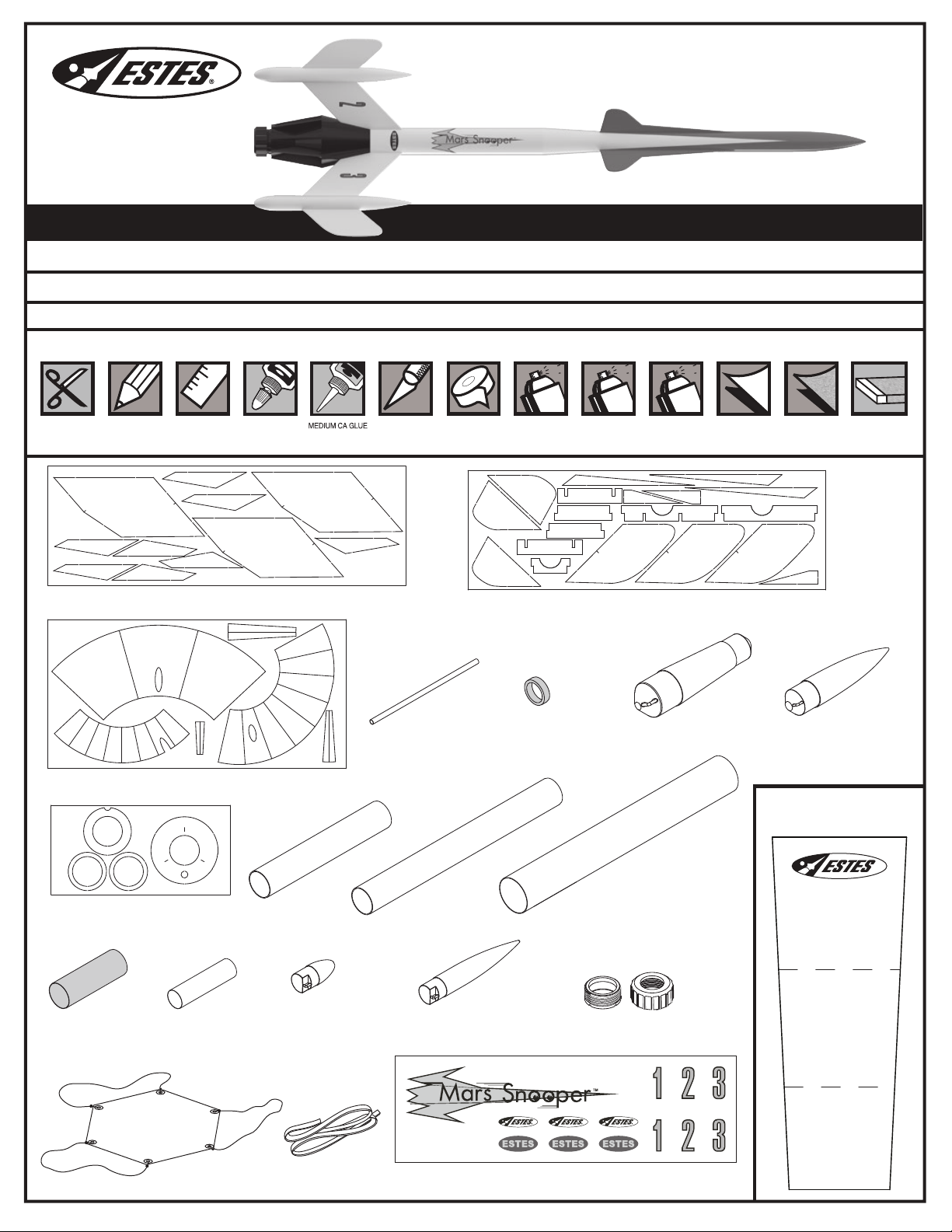
Read all instructions. Make sure you have all parts and supplies. Test fit all parts before applying glue.
SUPPLIES
7309
™
YELLOW GLUE
HOBBY KNIFE RULERPENCILSCISSORS
MASKING TAPE/
PAINTERS TAPE
PRIMER (WHITE)
X
N
N
Z
Z
BLACK, WHITE,
AND BLUE
F
B
U
(OPTIONAL)
U
H
G
FINE SANDPAPERWAX PAPERCLEAR COAT
AA
SAND BLOCK
B
X
N
090051A-7309
Laser cut wood sheet
X
Z
F
MMM
U
I
090051B-7309
Laser cut wood sheet
W
V
R
031398
P
Launch lug
C
D
090058-7309
Printed index stock
Q
B
030164-2
Green engine block
BB
073227
Transition
CC
073226
Nose cone
SHOCK CORD MOUNT
Make a copy if you want
E
T
S
S
090052-7309
Laser cut card stock
A
031396
Engine mount tube
Y
031395
Body tube
O
030472
Main body tube
to keep instructions.
3
Yellow spacer tool
035004 030408
KGG
x 3
Body tube
FF 035802
Parachute
x 3
L
073229
Nose cone
EE 038363
Shock cord
x 3
073228
Nose cone
© 2020 Estes Industries, LLC • All Rights Reserved.
Made in Guangdong, China • PN 090001-7309 (11-20)
DD
J
Engine retainer set
072417
2
1
090001-7309
Waterslide decals
1
Page 2

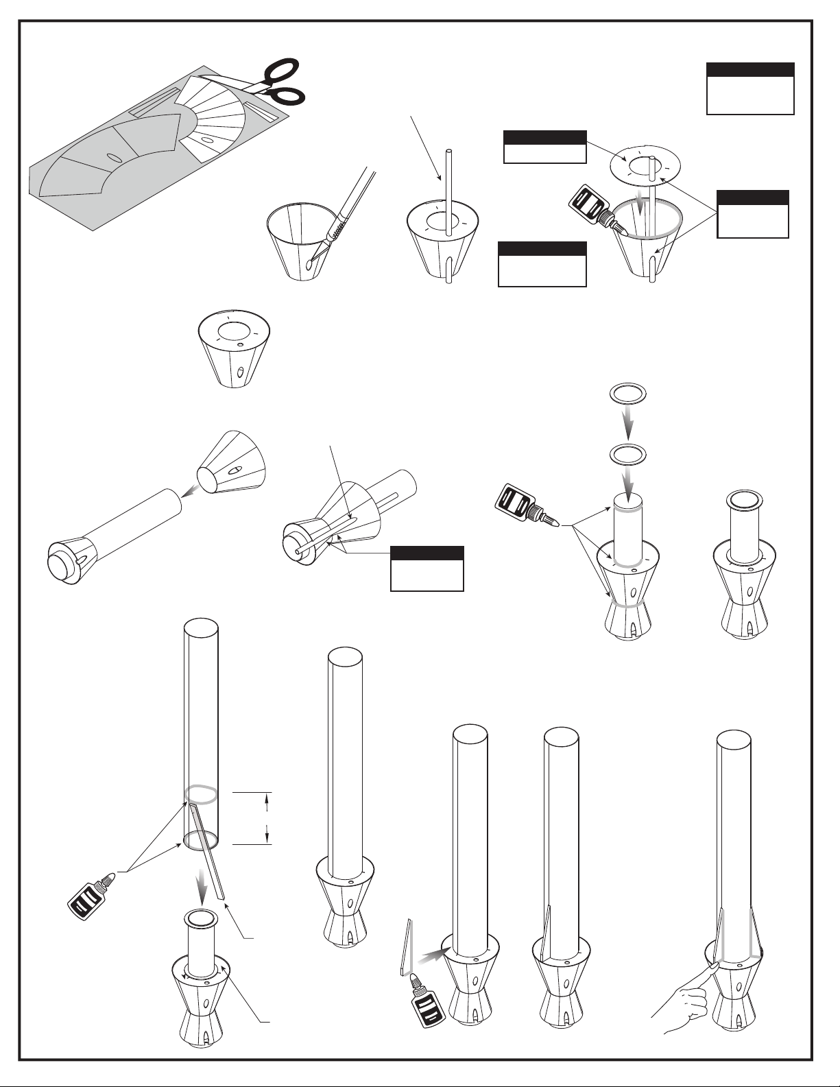
PREPARE WOOD PARTS, ASSEMBLE ROCKET CRADLE AND MAIN FINS
Apply glue to I and attach B as shown.
2.
1. Sand both sides.
Carefully remove with hobby knife.
U
F
AA
G
H
M
U
M
Apply glue to
Apply glue to
F
B and attach H as shown.
G and H and attach F as shown.
I
B
H
Z
Z
Z
I
3. Carefully remove with hobby knife.
X
N
X
G
F
LET DRY
4. Round edges.
N
N
Z
Z
Z
I
X
AA
G
H
M
M
U
M
M
N
6. Place fin tube
L
into rocket cradle.
5. Apply CA glue as shown.
J and L into K .
Insert
J
M
K
7. Using rocket cradle, glue M and N
to fin tube with CA glue.
N
8. Align marks on M and N with end of tube.
9. Apply yellow glue fillets to all fins.
Smooth with finger.
x 3
LET DRY
2
Page 3

MARK LOWER BODY TUBE
FIN
LINE
1.
FIN
LINE
LOWER TUBE MARKING GUIDE
Make a copy if you want to keep instructions.
FIN
LINE
Masking tape.
2.
O
ASSEMBLE PRINTED PAPER SHROUDS
Carefully remove
1.
with scissors.
W
V
P
FIN
LINE
FIN
LINE
FIN
LINE
LOWER TUBE MARKING GUIDE
Remove
4.
3.
Apply glue to one edge
3.
Curl wrap with
2.
printed side out.
Q
JOINER
of wrap and apply
joiner, centered over
edge as shown below.
Leave equal space
between the front and
back of joiner.
guide. Use
door frame
to extend
all lines.
DOOR FRAME.
NOTE:
Use this procedure
on all shrouds.
Apply glue to other
4.
edge and join
ends together.
Masking tape
5.
can be used to
hold joint
together until
glue dries.
D
C
ASSEMBLE ENGINE MOUNT
NOTE:
Align notches.
E
NOTE:
Always test fit parts before gluing.
Apply glue to inside edge
1.
of
C and attach E.
C
4. Quickly remove GG.
NOTE:
Lines on shroud
face outward.
A
5.
2. Mark GG as shown.
Insert
USE STICK
GG
3/8” (10 mm)
Place DD on end of A
as shown with ends even.
DO NOT GLUE. Slide
over A until C stops.
C
Apply glue inside
B.
B
A
A.
2 1/4” (5.7 cm)
C
A
3. Insert GG into A
Remove DD.
6.
Apply ring of CA glue as shown.
TAPE
stopping at mark on GG.
A
GG
LET DRY
GG
DD
DD
3
Page 4
ASSEMBLE LOWER SECTION OF MODEL
Carefully remove
1.
with scissors.
5.
W
V
Remove R, let dry.
6.
NOTE:
Test t R to conrm the
3.
P
alignment of openings.
Apply glue to one edge of
4.
Paper shroud and apply
Twill most likely be
T.
below edge of
P.
Q
NOTE:
Cut launch lug
2.
hole out with
hobby knife.
3 marks face up.
P
NOTE:
Always test fit parts
before gluing.
T
NOTE:
Align openings
R
using
P
S
Use R to conrm
7.
alignment of openings,
then remove.
Apply glue as shown.
8.
Attach
S.
S
Align marks
9.
on tube
with laser cut lines
on part
Apply glue
as shown.
T.
O
S
NOTE:
Lines on wraps
need to line up.
O
Apply glue to U
10.
in areas shown
and apply to
O.
S
O
2” (5.1 cm)
Apply glue llets
11.
to areas shown.
USE STICK
T
LET DRY
x 3
U
LET DRY
4
LET DRY
Page 5

ASSEMBLE LOWER DETAIL PARTS AND LAUNCH LUG ATTACHMENT
Carefully remove
1.
with scissors.
Apply glue as shown.
4.
X
Insert R and apply glue
5.
as shown.
Cut launch lug hole out with hobby knife.
2.
Apply glue as shown.
Apply glue llets
3.
as shown.
W
V
R
Use
R to conrm alignment
of openings.
V
NOTE:
Always test fit parts
before gluing.
x 8
Use hobby knife to trim R ush.
6.
LET DRY
R
ATTACH MAIN FINS
Apply glue as shown.
1. 2.
NOTE:
Marks need
to line up.
Apply glue llets as shown.
3.
Use n alignment guide to check alignment.
LET DRY
x 3
120˚
DISCARD
120˚
LET DRY
5
120˚
FIN ALIGNMENT GUIDE
Page 6

MARK UPPER BODY TUBE
FIN
1.
LINE
FIN
LINE
FIN
LINE
3.
Masking tape.
2.
Remove guide.
4.
Use door frame to
extend all lines.
DOOR FRAME
UPPER TUBE MARKING GUIDE
Make a copy if you want to keep instructions.
Y
FIN
LINE
FIN
LINE
FIN
LINE
UPPER TUBE MARKING GUIDE
ATTACH UPPER FINS
NOTE:
Assemble parts of at surface
covered with wax paper.
Apply glue to fins and
3.
attach to body tubes.
Use fin alignment guide
to check alignment.
Apply CA glue to inside of Y.
4.
Insert
CC and BB.
Y
Apply glue to edge of AA
1.
and attach Z.
Z
Y
CC
EVEN
Y
AA
LET DRY
LET DRY
x 3
2. Round edges of fins.
LET DRY
Apply glue flllets to all fins.
5.
x 3
120˚120˚
FIN ALIGNMENT GUIDE
120˚
INSTALL SHOCK CORD
1.
NOTE:
Cut from page 1.
BB
2.
EE
6. Glue shock cord
mount to the
inside of
O.
3.
2” (5.1 cm)
O
6
4. Hold until set.
LET DRY
5. Apply glue to
shock cord
mount.
7.
2” (5.1 cm)
Use finger to hold
until glue sets.
Page 7
DD
LET DRY
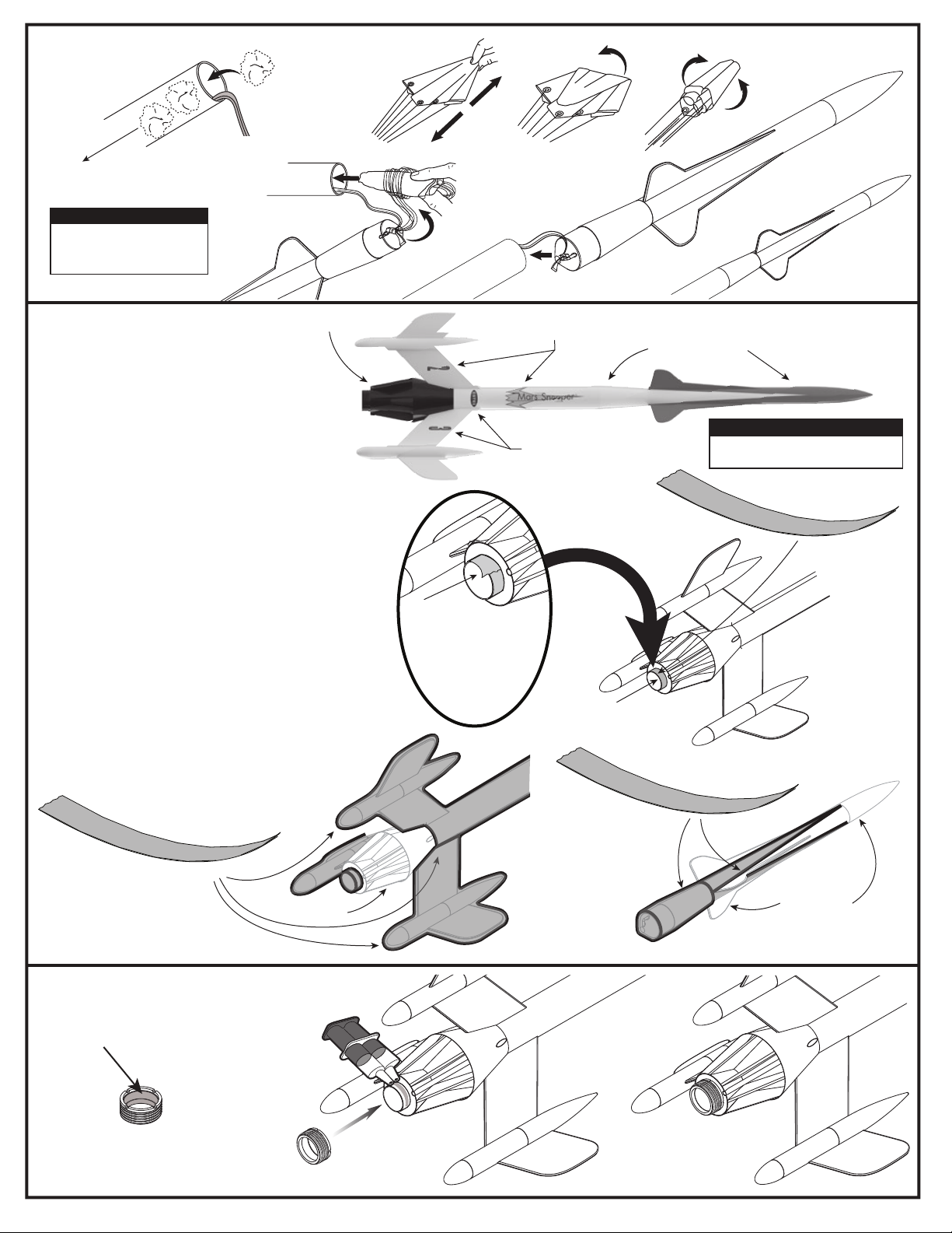
ATTACH SHOCK CORD
1. Push recovery wadding
down towards end of
body tube.
NOTE:
Recovery wadding and
parachute must slide easily into
body tube. If too tight, redo.
RECOVERY WADDING
5. Wrap shroud lines
loosely and insert
parachute into body tube.
5-6 SQUARES
ESTES®
2.
3.
6. Insert nose cone
into body tube.
4.
7.
ROCKET FINISHING
Step 1.
Wrap masking tape around end of A to protect its surface from
primer and paint.
Step 2.
Spray rocket and nose cone with white primer.
Let dry and sand. Repeat until surface is smooth.
Step 3.
Spray rocket with several lights coats of white paint, allowing
to dry between coats.
Step 4.
Apply masking tape to the edges of all lower ns where they
meet the rocket body. Cover the rest of the rocket to avoid
getting black paint on it.
Step 5.
Spray area with several lights coats of black paint, allowing to
dry between coats. When completely dry, carefully remove
masking tape and covering.
Step 6.
Apply masking tape as indicated, forming a V between each
upper n. Cover the rest of the rocket to avoid getting blue
paint on it. Spray nose cone with several light coats of blue
paint, allowing to dry between coats. When completely dry,
remove masking tape and covering.
Step 7.
Once rocket is completely dry, cut decals from sheet, trimming
close to edge.
Step 8.
One at a time, place in warm water until decal curls and begins
to relax.
Step 9.
Remove and position on rocket, sliding away from backing
material.
Step 10.
Blot with paper towel. Let dry overnight.
Step 11.
OPTIONAL: Apply protective clear coat to entire rocket. Let
dry.
Step 12.
Remove masking tape from A.
BLACK PAINT
Step 4.
MASKING TAPE
OR PAINTERS TAPE
A
WRAP
TAPE AROUND END OF
TO PROTECT ITS
SURFACE
FROM PRIMER
AND PAINT.
DECALS
DECALS
Step 1.
A
WHITE PAINT
A
BLUE PAINT
NOTE:
Please refer to packaging for suggested
paint scheme and/or decal placement.
MASKING TAPE
OR PAINTERS TAPE
MASKING TAPE
OR PAINTERS TAPE
INSTALL ENGINE RETAINER
1. Lightly sand the inside of DD
so epoxy adheres better.
DD
BLACK PAINT
2. Apply epoxy to A
and attach DD.
Step 6.
BLUE PAINT
7
Page 8
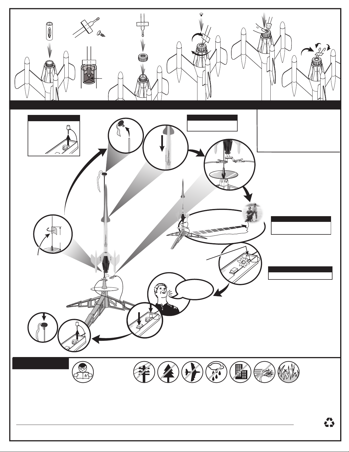
PREPARE ENGINE
STARTER
1.
Use 1 each.
TIP MUST TOUCH
PROPELLANT!
COUNTDOWN AND LAUNCH
NOTE:
Key always out until nal
countdown!
PLUG
2.
2.
3.
3.
NOTE:
Requires 3/16” Two-Piece
®
Launch Rod.
Maxi
4.
4.
5.
ESTES® LAUNCH SUPPLIES NEEDED
(Sold Separately)
• Porta-Pad
• Electron Beam
• Recovery Wadding
• Starters (with engines)
• Plugs (with engines)
• Estes
®
II Launch Pad
®
Launch Controller
®
Engines: C11-3, D12-3
1.
MASKING TAPE
10.
PRECAUTIONS
3”
(7.6 cm)
9.
NAR SAFETY CODE
8.
7.
5.
NOTE:
16.4 ft. (5 m)
Fully extend your launch controller wire
before launching.
6.
KEY
NOTE:
Estimated weight :
4...
3...
2...
1...
While holding key down FIRMLY, press launch button until LIFTOFF!
Insert key, push down hard. Bulb will light.
5.5 oz. (155.9g)
NO DRY GRASS
OR WEEDS
PRE-LAUNCH CHECK For safety, never launch a damaged rocket. Check the rocket's body, nose cone and ns. Also, check the engine mount, recovery system and launch lug(s).
Repair any damage before launching the rocket.
FLYING YOUR ROCKET Choose a large eld (500 ft. [152 m] square) free of dry weeds and brown grass. The larger the launch area, the better your chance of recovering your rocket.
Football elds and playgrounds are great. Launch only with little or no wind and good visibility. Always follow the National Association of Rocketry SAFETY CODE (enclosed).
MISFIRES TAKE THE KEY OUT OF THE CONTROLLER. WAIT ONE MINUTE BEFORE GOING NEAR THE ROCKET. Disconnect the micro-clips and remove the engine. Take the
plug and starter out of the engine. A burned starter means the starter tip was not touching engine propellant. Install a new starter; be sure the tip is touching propellant inside the
engine. Push the plug in place. Repeat steps under Countdown and Launch.
© 2020-2021 Estes Industries, LLC. All rights reserved.
Estes Industries, LLC, 1295 H Street, Penrose, CO 81240-9698. Made in Guangdong, China. PN 090004-7309 (4-21)
8
22
PAP
 Loading...