

Page 1
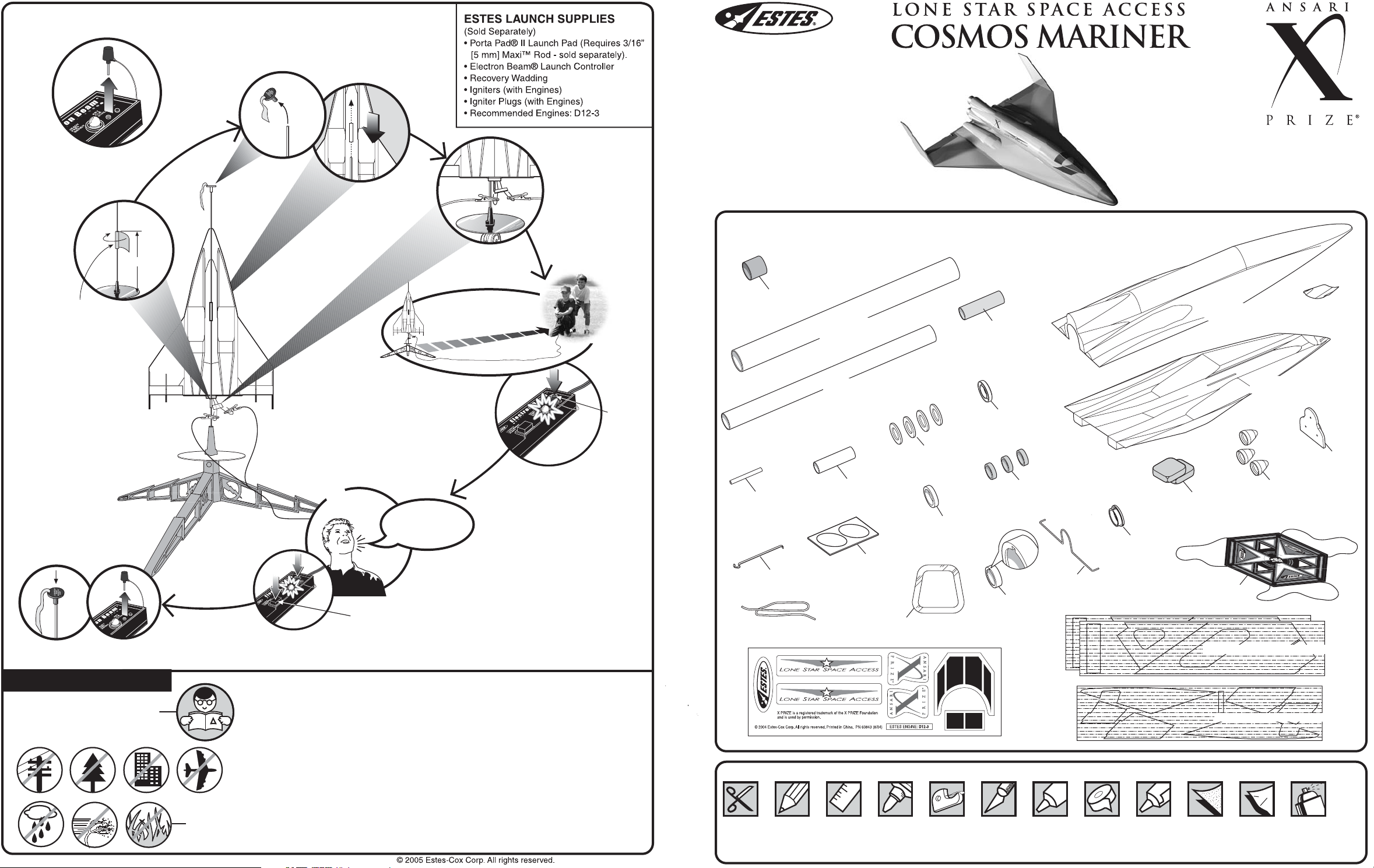
COUNTDOWN AND LAUNCH
KEY
ALWAYS
OUT UNTIL FINAL
COUNTDOWN!
2...
2...
www.estesrockets.com
ESTES INDUSTRIES
1295 H Street
Penrose, CO 81240
PRINTED IN CHINA
ASSEMBLY TIP: Read all
instructions before beginning work on
your model. Make sure you have all
parts and supplies.
TEST FIT ALL PARTS TOGETHER
BEFORE APPLYING ANY GLUE!
If any parts don't fit properly, sand as
required for precision assembly.
#2190
FLYING MODEL
ROCKET KIT
INSTRUCTIONS
KEEP FOR FUTURE
REFERENCE
X PRIZE is a registered trademark
of the X PRIZE Foundation and is
used by permission.
1...
1...
MASKING
TAPE
NOTE: So that you
don't loose sight of
your glider or
engine pod, it's a
good idea to have
another person
observe the
launch and
recovery, as the
glider and engine
pod descend
separately.
10" (25.4 cm)
3...
3...
15 FT. (5 M)
4...
4...
5...
5...
4... 3... 2... 1...
HOLD KEY DOWN AND
PRESS LAUNCH BUTTON
UNTIL
LIFTOFF!
INSERT KEY.
PUSH DOWN
FIRMLY AND
HOLD.
KEY
PARTS Locate the parts shown below and lay them out on the table in front
of you. DO NOT USE THIS DRAWING TO ASSEMBLE YOUR ROCKET.
BLACK ENGINE
HOOK RETAINER
RING (1) (30160)
LAUNCH LUG
3/16" X 2" LL-3B (1)
(38166)
ENGINE HOOK
EH-2 (1) (35021)
ELASTIC THREAD
ET-1 (1) (85772)
FUSELAGE TUBE
BT-55 (1) 14-1/8" (35.9
cm) (30470)
ENGINE POD TUBE BT1000 (1) 13-7/16" (34.1 cm)
(30471)
WEIGHT ASSEMBLY
TUBE BT-760 (1)
(30472)
DIE CUT
CARD (1)
(32477)
DOUBLE-SIDED
DOOR TAPE (2)
(60988)
STEEL WASHER
(4) (38330)
BULKHEAD RING
AR-76055 (GREEN)
(1) (30133)
YELLOW
SPACER TOOL
(1) (35004)
PLASTIC
POD CAP
(1) (60971)
CENTERING RING
(GREEN) AR-76050
(3) (30004)
PLASTIC
POD RING
(1) (60970)
WIRE FORM
(1) (60987)
PLASTIC
POD END
RING (1)
(60969)
UPPER FUSELAGE
(1) (60966)
CLAY WEIGHT (2)
(85705)
ASSEMBLED
PARACHUTE 18"
(46 CM) (1) (35802)
LASER CUT BALSA SHEET (2) (32230)
PLASTIC DOOR
(1) (60968)
BOTTOM FUSELAGE
(1) (60967)
PLASTIC
DISPLAY
NOZZLE (3)
(60973)
PLASTIC
DISPLAY
NOZZLE
BASE (1)
(60972)
PRECAUTIONS
NAR Safety Code
page 12
NO DRY GRASS
OR WEEDS
FLYING YOUR ROCKET
Choose a large field (500 ft. [152 m] square) free of dry weeds and brown grass.
The larger the launch area, the better your chance of recovering your rocket. Football
fields and playgrounds are great. Launch only with little or no wind and good visibility.
Always follow the National Association of Rocketry (NAR) SAFETY CODE.
MISFIRES
TAKE THE KEY OUT OF THE CONTROLLER. WAIT ONE MINUTE BEFORE
GOING NEAR THE ROCKET!
the plug and igniter out of the engine. If the igniter has burned, it worked but did
not ignite the engine because it was not touching the propellant inside the engine.
Put a new igniter all the way inside the engine without bending it. Push the plug in
place. Repeat the steps under Countdown and Launch.
Disconnect the igniter clips and remove engine. Take
PN 60842 (02-05)
DECAL SHEET (1) (60843)
SUPPLIES In addition to the parts included in the kit you will also need:
SCISSORS
PENCIL RULER
CARPENTER'S
GLUE
CELLOPHANE
TAPE
MODELING
KNIFE
SILICONE
ADHESIVE
MASKING
TAPE
PLASTIC
CEMENT
LASER CUT BALSA SHEET (1) (32231)
SAND
PAPER
• SPRAY PRIMER
WAX
• SPRAY PAINT
PAPER
(TAN, GOLD, GRAY)
• SPRAY CLEAR COAT
(OPTIONAL)
Page 2
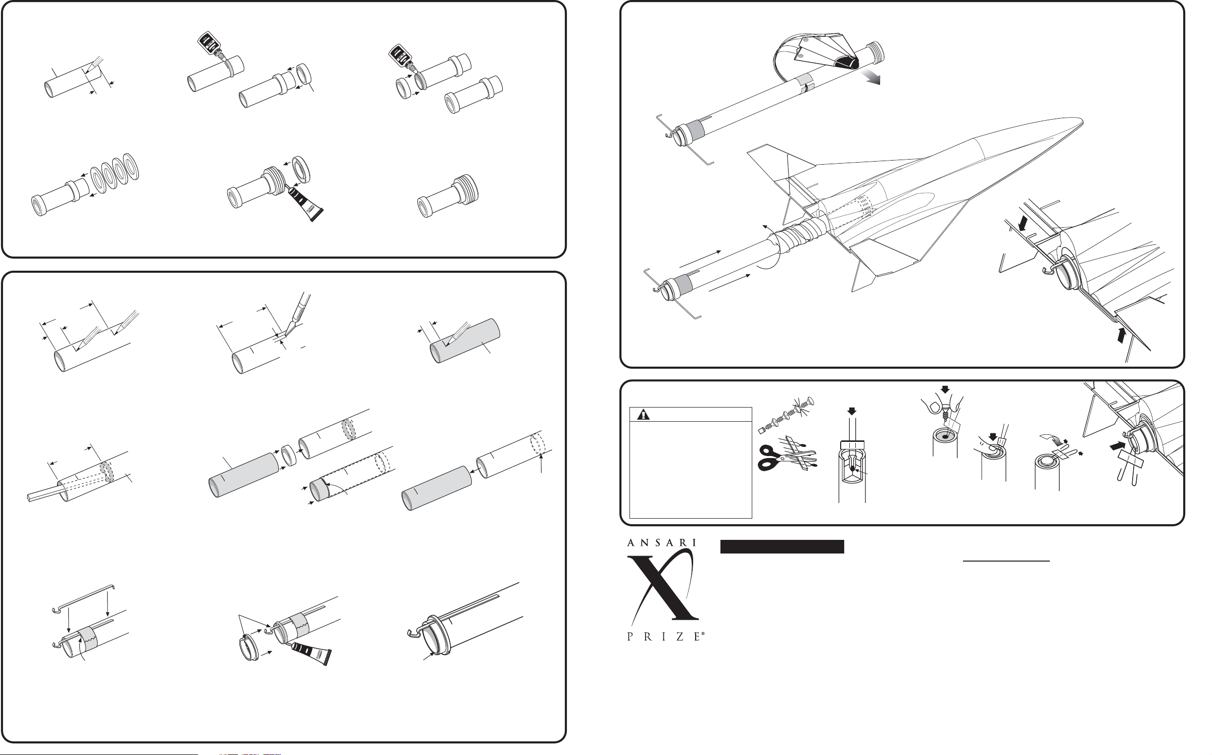
1. ASSEMBLE ENGINE POD WEIGHT ASSEMBLY
WEIGHT
ASSEMBLY TUBE
7/8" (22 mm)
A. Mark tube 7/8" (22 mm)
from front.
B. Apply glue around tube in front of
7/8" (22 mm) mark. Slide centering
ring onto tube up to mark. Let dry.
GREEN
CENTERING
RING
C. Apply glue around rear end of
tube. Slide centering ring onto
tube, flush with the end. Let dry.
15. PREPARE FOR FLIGHT
Note position of engine pod tube.
A. Spike parachute and roll
shroud lines and parachute
around power pod.
D. Slide four steel washers onto tube.
E. Apply plastic cement around end of
tube. Slide pod cap onto tube, tight
against washers. Let dry.
2. ASSEMBLE ENGINE POD ASSEMBLY
2-1/4"
(5.7 cm)
3/4"
(19 mm)
A. Measure and mark engine pod
tube 3/4" (19 mm) and 2-1/4"
(5.7 cm) from end.
2" (5 cm)
D. Use scrap balsa to smear glue
2" (5 cm) inside engine pod tube.
3/4" MARK (19 mm)
F. Position and insert engine hook
into slit as shown. Temporarily
hold hook into place with masking
tape at 3/4"
page 2
(19 mm) mark.
ENGINE POD
TUBE
B. Cut a 1/8" (3 mm) slit at
the 2-1/4" (5.7 cm) mark.
YELLOW
SPACER TUBE
ALIGN NOTCH
WITH ENGINE
G. Apply a bead of plastic cement around
end of tube. Align plastic pod end
ring with notch over engine hook.
Slide into place, flush with end of
tube. Check that engine hook is
straight with body tube. Let dry.
FRONT
YELLOW
SPACER TUBE
2-1/4"
(5.7 cm)
1/8"
(3 mm)
REAR
COMPLETED ASSEMBLY
1/2"
(13 mm)
C. Mark yellow spacer tool
1/2" (13 mm) from end.
1/2" MARK
(13 mm)
AS AN ENGINE
E. Using yellow spacer tool, push remaining green centering ring into tube
up to 1/2"
(13 mm) mark.
Remove yellow spacer tool immediately.
Let dry.
HOOK
REAR
FLUSH WITH
END OF TUBE
H. Remove masking tape.
CENTERING
RING IS USED
BLOCK
FRONT
B. Insert pod tube into fuselage tube using a
twisting motion. Fit should not be too tight. If
tight, remove pod and roll parachute around
pod tube tighter. Reinsert pod into glider.
PREPARE ENGINE
WARNING: FLAMMABLE
To avoid serious injury, read
instructions & NAR Safety Code
included with engines.
PREPARE YOUR ENGINE
ONLY WHEN YOU ARE
OUTSIDE AT THE LAUNCH
SITE PREPARING TO
LAUNCH!
If you do not use your prepared
engine, remove the igniter before
storing your engine.
TEAM OVERVIEW
LONE STAR SPACE ACCESS TEAM
Lone Star Space Access Corporation is a
research and development company
dedicated to developing the technologies
necessary for a space faring civilization.
The goal of the company is to develop the
enabling technologies for affordable and
routine access to space for the purpose of
exploration and utilization. The company is
composed of a team of professionals
working in a concurrent development
environment on a variety of technologies.
Their goal is to create the technology and
capability necessary to allow mankind to
reap the full benefits of the utilization of
space and to spin off these technologies for
commercial development in other nonaerospace applications.
A. Separate
igniter and
plug.
IGNITER MUST
TOUCH
PROPELLANT!
B. Insert igniter.
LEFT
ELEVATOR
DOWN
C. Slip wire form ends
over left elevator and
right wing.
RIGHT
ELEVATOR
UP
C. Insert
plug.
D. Push
down.
E. Gently bend
wires to form
F. Insert engine
into rocket.
leads as shown.
TEAM SPECIFICATIONS
Name: Lone Star Space Access Team
Web Site:
Country of Origin: Houston, Texas, USA
VEHICLE SPECIFICATIONS
Name: ................................................Cosmos Mariner
Length: ...............................................100 feet (31 m)
Wingspan:........................................... 73 feet (22 m)
GTOW: ............................................... 136,000 Lbs
DRY WT.: ............................................ 30,000 Lbs
Engines: .............................................Three staged-combustion
Total Thrust: .......................................90,000-lbs
Payload Capacity: ..............................3 crew members.
Crew Environment: .............................Short-sleeved, pressurized cabin.
MISSION SPECIFICATIONS
Launch Method: .................................Horizontal takeoff from ground
Max. Acceleration Force: ....................3-4 Gs
Max. Speed: .......................................Mach 7
Max. Altitude: .....................................75 miles (120 km)
Time in Weightless Conditions: ..........10 minutes
Landing Method: ................................Conventional runway
Total Flight Duration: ..........................2 hours (including flight back to
............................................................launch point)
www.lonestarspace.com
page 11
Page 3
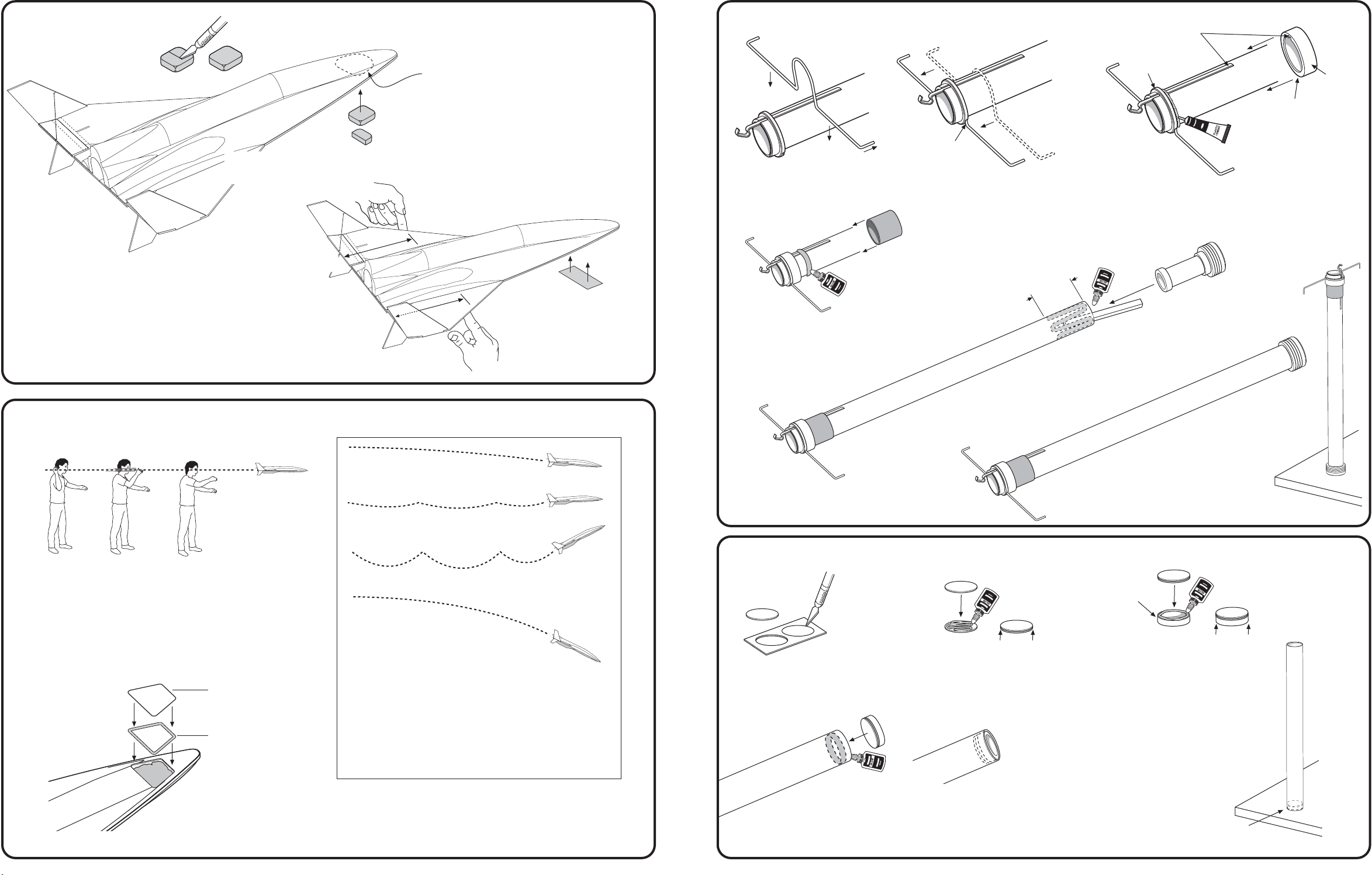
13. BALANCE GLIDER
CUT ONE CLAY
WEIGHT IN HALF
A. Insert 1-1/2 squares of clay
into cavity located on
bottom front of fuselage.
7-1/8" to 7-3/8"
(18.1 to 18.7 cm)
B. Add or subtract clay weight until
glider balances between 7-1/8" to
7-3/8" (18.1 to 18.7 cm) from rear of
glider. Hold clay in place
temporarily with masking tape.
HOLD CLAY
TEMPORARILY
WITH MASKING
TAPE
2. ASSEMBLE ENGINE POD ASSEMBLY (continued)
NOTCHES
TIPS
FORWARD
I. Align wire form as shown, tips forward. Loop goes over tube.
Press wire form rearward until it fits into notches in the plastic
pod end ring.
1-1/2"
(3.8 cm)
K. Apply a ring of glue around tube
ahead of the plastic pod ring.
Slide the black engine hook
retainer ring rearward and under
the ring until tight against ring.
Let dry.
FLAT
SIDE
FRONT
PLASTIC
PLASTIC
POD END
RING
REAR
ALIGN
J. Align notch in plastic pod ring with engine hook. Apply
plastic cement around front edge of the plastic pod
end ring. Slide plastic pod ring down tube, making
sure the wire form is trapped between the two rings.
Let dry. Note: Wipe off any excess cement.
L. Use scrap balsa to smear
glue 1-1/2"
(3.8 cm) inside
of tube. Insert engine pod
weight assembly into
tube, flush to end.
POD
RING
NOTE: Test the glider only on soft, grassy surfaces like a sports field
14. GLIDE TEST
or lawn so that you don't damage your model.
A. With engine pod removed from glider, aim for a spot about
50 feet (15 m) away and toss glider straight out at eye level.
B. Observe glide carefully. Make adjustments a little at a time
until you are satisfied with the glide.
DOOR
DOUBLE-SIDED
DOOR TAPE
Once you are satisfied with the glide, remove the tape that holds the
clay in place, being careful not to dislodge any of the clay. Remove
backing from double-sided door tape and apply tape to plastic door.
Remove other side of backing and attach door to fuselage, pressing
door firmly onto fuselage and securing clay weight in place.
CORRECT FLIGHT-
SLOW LOSS OF
ALTITUDE
LIGHT STALL-OK
HEAVY STALL-
CORRECT IT
DIVE-DON'T LET THIS
HAPPEN TO YOU
GLIDER ADJUSTMENTS:
If glider dives, remove clay weight from cavity.
If glider stalls, add clay weight to cavity.
If glider turns too sharply, make sure it is balanced
span wise (from side to side). If it is not, add
weight, in small amounts, to the light wing tip until
nearly balanced.
The glider should perform a large, gliding circle
during descent.
3. ASSEMBLE FUSELAGE TUBE
A. Carefully remove discs from card
using a modeling knife. Sand
edges smooth to remove any nibs.
D. Apply a ring of glue just inside end of fuselage
tube. Insert disc side of bulkhead assembly into
tube, flush with end.
B. Apply glue to top of one disc.
Press both discs together,
align evenly. Let dry.
EVEN
COMPLETED
ENGINE POD TUBE
ASSEMBLY
BULKHEAD
RING
EVEN
C. Apply glue to bulkhead ring
and attach discs. Wipe off
any excess glue. Let dry.
E. Stand upright on bulkhead
end until completely dry.
Do not lay on its side.
BULKHEAD END
NOTE: STAND
UPRIGHT UNTIL
COMPLETELY
DRY!
COMPLETED
FUSELAGE
ASSEMBLY
page 3page 10
Page 4
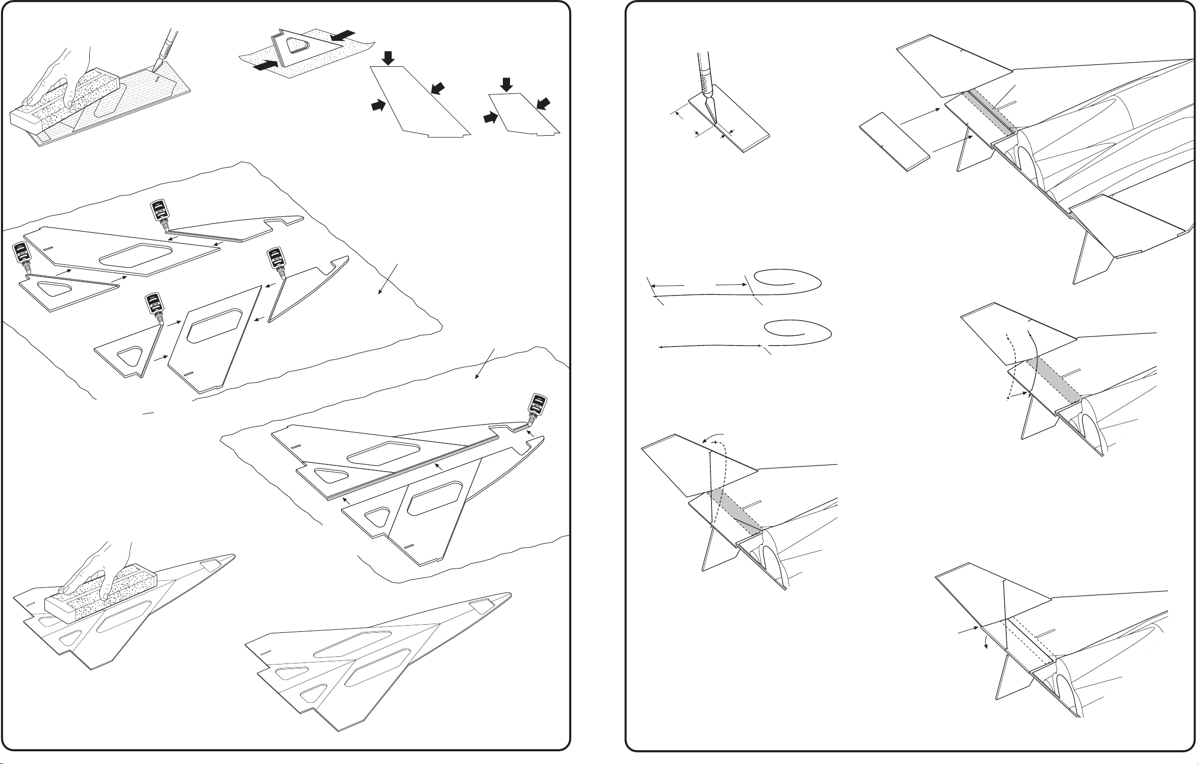
4. ASSEMBLE WING
A. Sand balsa sheets
smooth, both sides.
B. Using a modeling
knife, carefully
remove balsa
parts from sheets.
C. Sand edges
smooth to remove
any nibs. Keep
edges square and
do not round.
CAUTION: Do not sand
off the tabs on top and
bottom stabilizers!
NOTE: On these parts, sand
only the edges indicated
with arrows.
TOP VERTICAL
STABILIZER
BOTTOM
STABILIZER
12. ATTACH LEFT ELEVATOR AND ELASTIC THREAD
1-5/8"
(4.1 cm)
A. Using a modeling knife, cut a
1/8" (3 mm) slit, 1-5/8" (4.1 cm)
from left of elevator as shown.
1/8"
(3 mm)
CELLOPHANE
TAPE
D. Place a piece of wax paper on
a flat surface. Line up balsa
wing pieces as shown. Glue left
and right wings together as
shown.
E. After alignment, place another piece
of wax paper on top of wings. Place
a book on top and let dry completely.
LEFT
NOTE: Accurate
alignment is critical
for fuselage fit.
RIGHT
NOTE: Place a piece of wax
paper on a flat surface prior to
assembling balsa wing parts.
WAX PAPER
WAX PAPER
B. Position elevator at rear of left wing as
2" (5 cm)
DOUBLE KNOT
DOUBLE KNOT
TRIM
C. Tie a double knot near one end of elastic cord, and
another 2" (5 cm) from first knot. Trim as shown.
shown. Apply a strip of cellophane tape
centered over seam. Press down securely,
especially along seam. Fold elevator up and
down several times to crease the "hinge"
and ensure proper operation.
D. Insert thread into slit on elevator as shown.
F. After wings are completely
dry, align and glue
together as shown. Place
a piece of wax paper on
top of wing, place a book
on top and let dry
completely.
E. Wrap elastic thread around vertical
stabilizer and insert into slit with knot
on the outboard side of stabilizer.
ELEVATOR SHOULD FIT
SNUG AGAINST BOTTOM
OF STABILIZER, BUT
STILL HAVE MOVEMENT
G. Sand both sides smooth.
page 4 page 9
COMPLETED WING
ASSEMBLY
COMPLETED ASSEMBLY
Page 5
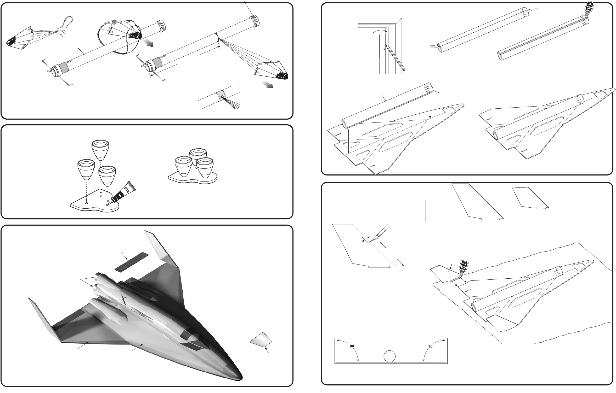
9. ATTACH PARACHUTE
ENGINE
POD TUBE
5. ATTACH FUSELAGE TUBE TO WINGS
DOOR
FRAME
MARK
END
A. Form a loop in the shroud lines, wrap around engine pod tube, pass
'chute through loop. Position at 10" (25.4 cm) from rear and pull tight.
10. ASSEMBLY DISPLAY BASE
PLASTIC
NOZZLES
A. Apply plastic cement
into the three holes in
display base. Insert
"pins" on nozzles into
holes in base. Let dry.
11. FINISHING YOUR ROCKET
PLASTIC
DISPLAY BASE
(25.4 cm)
10"
LET DRY
COMPLETED DISPLAY BASE
B. Secure to
engine pod tube
with a band of
masking tape.
CAUTION: For display purposes only.
Do not glue to end of glider.
A. Using a door frame,
draw a line the
MARK
END
entire length of the
tube.
FUSELAGE TUBE
ASSEMBLY
REAR
C. Glue tube to wing assembly. Align
marks on tube with center wing joint,
flush with end of wings as shown.
Let dry completely.
6. ATTACH VERTICAL STABILIZERS
LOCATE THE FOLLOWING PARTS:
LEADING
EDGE
ELEVATORS (2)
B. Mark both ends as shown and apply a bead of glue on line.
FRONT
BULKHEAD
TIP
TRAILING EDGE
LEADING EDGE
TOP VERTICAL
STABILIZERS (2)
TAB
TIP
TRAILING EDGE
BOTTOM
STABILIZERS (2)
LEADING EDGE
TAB
COMPLETED
ASSEMBLY
A. First spray rocket with white primer,
except for internal tube. Let dry and
sand. Repeat until rocket is smooth.
FOLLOW THE PAINT SCHEME ON
THE PACKAGE.
GOLD
GRAY
OPTIONAL: Spray a clear coat on entire rocket
after paint dries and after decal placement.
LEFT
ELEVATOR
TAN
B. When paint is dry, peel decals one at
a time from backing sheet and apply
where shown. Rub down to remove
bubbles.
PLASTIC
DOOR
TAN
1/8"
(3 mm)
2" (5 cm)
A. Measure and mark one top
vertical stabilizer at 2" (5 cm).
Cut a 1/8" (3 mm) slit as shown.
NOTE: This will be the LEFT top stabilizer.
END VIEW
SLIT
LEFT
RIGHT
B. Place a sheet of wax paper on a flat surface.
Apply glue to the tab on left stabilizer with
slit and attach as shown. Repeat for right
stabilizer. Make sure they are at 90 degrees
to the wings. Let dry completely.
page 5page 8
Page 6
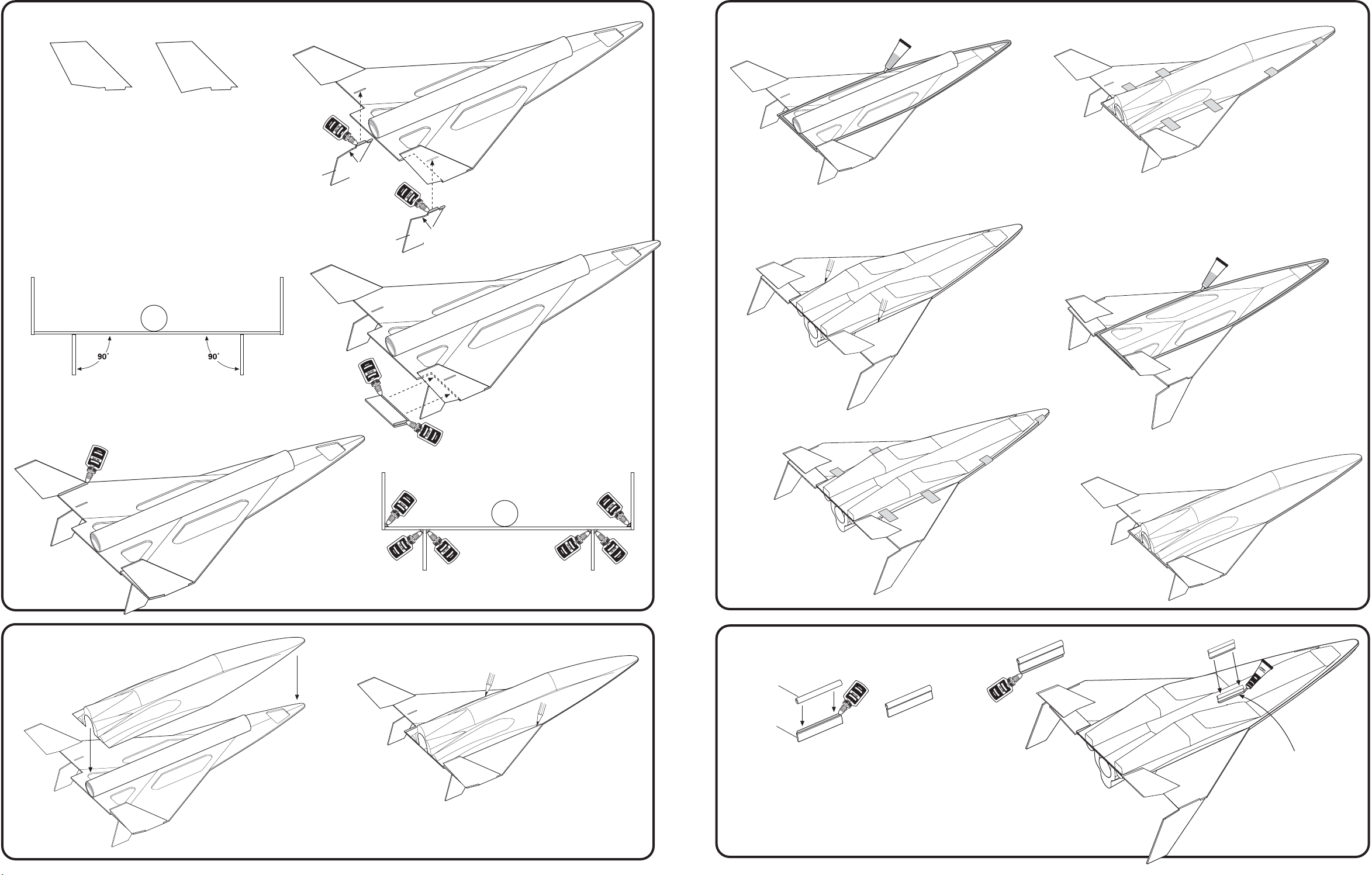
6. ATTACH VERTICAL STABILIZERS (continued)
7. ATTACH FUSELAGE TOP AND BOTTOM (continued)
LEFT BOTTOM
STABILIZER
RIGHT BOTTOM
STABILIZER
Note difference between left and right bottom stabilizers.
C. Apply glue to bottom
left stabilizer. Align tab
on stabilizer with slot
in wing and attach
stabilizer to wing.
Repeat for right
bottom stabilizer.
END VIEW
NOTE: Top and bottom stabilizers must be
attached correctly for stable flight.
LEFT
BOTTOM
STABILIZER
NO
GLUE
RIGHT
BOTTOM
STABILIZER
NO
GLUE
D. Apply glue to one of the elevators
as shown. Attach to the right wing.
Hold in place with tape. Let dry.
B. Apply a 1/8" (3 mm) bead of silicone adhesive
just inside pencil lines and just inside wing
edge as indicated.
E. Support fuselage/wing
assembly. Center
fuselage bottom on
wing as shown. Trace
shape with pencil.
Remove fuselage.
C. Attach fuselage top to wing and secure in place
with masking tape. Let dry overnight.
D. After it is completely dry, carefully trim/sand excess
plastic of fuselage top to match with shape of wing.
F. Apply silicone
adhesive just inside
pencil tracing and just
inside edge of wing.
7. ATTACH FUSELAGE
TOP AND BOTTOM
page 6
E. Apply glue fillets top and bottom
of joints. Smooth glue with finger.
Let dry completely.
A. Place wing assembly on flat surface with bottom stabilizers
hanging over edge. Place fuselage top on wings as shown.
Trace along both edges. Remove fuselage.
END VIEW
G. Attach fuselage bottom
and hold in place with
tape. Let dry overnight.
8. ATTACH LAUNCH LUG
LAUNCH
LUG
BALSA
STANDOFF
A. Apply glue to standoff
and center launch lug.
Let dry.
COMPLETED
ASSEMBLY
H. Carefully trim/sand excess
plastic of fuselage bottom
to match with shape of wing.
B. Apply glue to bottom of standoff.
Position launch lug assembly into slot
in fuselage bottom. Let dry.
COMPLETED
ASSEMBLY
Apply a fillet of
plastic cement to
both sides of the
fuselage/standoff
joint. Let dry.
page 7
 Loading...