

Page 1

COUNTDOWN AND LAUNCH
8” (20.3 cm)
KEY ALWAYS OUT
UNTIL FINAL
COUNTDOWN!
1...
1...
MASKING
TAPE
2...
2...
3...
3...
15 FT (5 m)
www.estesrockets.com
ESTES INDUSTRIES
1295 H Street
Penrose, CO 81240
PRINTED IN CHINA
CANADIAN ARROW
FLYING MODEL ROCKET KIT INSTRUCTIONS
KEEP FOR FUTURE REFERENCE
ASSEMBLY TIP: Read all instructions before
beginning work on your model. Make sure you
have all parts and supplies.
TEST FIT ALL PARTS TOGETHER
BEFORE APPLYING ANY GLUE!
If any parts don't fit properly, sand as required
for precision assembly.
Canadian Arrow
#2188
X PRIZE is a registered trademark of the
X PRIZE Foundation and is used by permission.
Use 3/16” (5 mm)
Maxi™ Rod
PRECAUTIONS
NAR Safety Code
LAUNCH
BUTTON
4... 3... 2... 1...
HOLD KEY DOWN
AND PRESS
BUTTON UNTIL
LIFT-OFF!
4...
4...
ESTES LAUNCH SUPPLIES
(Sold Separately)
• Porta Pad® II Launch Pad (Requires 3/16”
[5 mm] Maxi™ Rod - sold separately).
• Electron Beam® Launch Controller
• Recovery Wadding
• Igniters (with engines)
• Igniter Plugs (with engines)
• Recommended Engines: D12-3, D12-5
INSERT
KEY. PUSH
DOWN
AND
HOLD.
NO DRY
GRASS
OR
WEEDS
PARTS
Locate the parts shown below and lay them out on the table in front of
you. DO NOT USE THIS DRAWING TO ASSEMBLE YOUR ROCKET.
Nose Cone PNC-80K (1)
(71035)
Engine Mount Tube BT-50H (1)
(30360)
Black Engine Hook Retainer
Tail Cone PTC-80 (1)
(71033)
Yellow Spacer Tool (1)
Ring (1) (30480)
Rubber Shock Cord 1/4” x 30” (1)
(38369)
(35004)
Body Tube BT-80C (1)
(30458)
Green Engine Block
AR2050 (1) (30164-2)
Launch Lug 3/16” LL-12 CF (1)
(38166)
Engine Hook EH-2 (1)
(35021)
Clay Weight (2)
(85705)
FLYING YOUR ROCKET
Choose a large field (500 ft. [152 m] square) free of dry weeds and
brown grass. The larger the launch area, the better the chance of
recovering your rocket. Football fields and playgrounds are great.
Launch only with little or no wind and good visibility.
Always follow the National Association of Rocketry (NAR)
Safety Code.
TEAM OVERVIEW
The Canadian Arrow team is highly motivated to fulfill the dream
of popular space travel using the “don’t reinvent the wheel” approach.
8
By making use of the research performed over 60 years ago, this
Canadian team plans to bring the V2 rocket back to life, but this
time for the benefit of the space tourism industry.
Canadian Arrow
MISFIRES
TAKE THE KEY OUT OF THE CONTROLLER. WAIT ONE MINUTE
BEFORE GOING NEAR THE ROCKET! Disconnect the igniter clips and
remove the engine. Take the plug and igniter out of the engine. If the igniter
has burned, it worked but did not ignite the engine because it was not
touching the propellant inside the engine. Put a new igniter all the way
inside the engine without bending it. Push the plug in place. Repeat the
steps under Countdown and Launch.
TEAM SPECIFICATIONS:
Name: Canadian Arrow. Website: www.canadianarrow.com
Country of Origin: London, Ontario, Canada
VEHICLE SPECIFICATIONS:
Name: Canadian Arrow
Length: (1st, 2nd Stage): 54 feet (33.5 feet, 20 feet) Diameter: 5.4 feet. GTOW:
31,000 lbm. Dry Weight: 12,500 lbm. Engines (1st, 2nd Stage): 1,4. Total Thrust:
(1st, 2nd Stage): 57,000 lbf, 17,600 lbf. Payload Capacity: 3 passengers (900 lbm).
Crew Capsule Environment: Pressurized to atm plus full pressure suits for crew.
MISSION SPECIFICATIONS:
Launch Method: Vertical Take-off from ground. Max Accel. Force on Ascent: 5.4g
for 3 sec. Max Speed: Mach 4 (2,966 mph). Max. Altitude: 70 miles (113 km). Time
in Weightless Conditions: 4 minutes. Landing Method: Ocean splashdown via
parachute. Total Flight Duration: ~45 minutes.
© 2004-2005 Estes-Cox Corp. All rights reserved.
P/N 60836 (3-05)
Laser Cut Balsa Fins (2)
(32626)
SUPPLIES
PENCIL
RULER
Die Cut Centering Rings (1)
(32434)
Assembled Parachute 18” (46 cm) (1)
(35802)
In addition to the parts included in the kit you will also need:
FINE
SAND
PAPER
(#400-600 Grit)
CARPENTER’S
GLUE
MODELING
KNIFE
SANDING
BLOCK
RAZOR
SAW
TUBE-TYPE
PLASTIC
CEMENT
MASKING
TAPE
PLASTIC
MODELING
PUTTY
SPRAY
PRIMER
(WHITE)
Decal Sheet (1)
(60837)
SPRAY
PAINT
(REFER TO
STEP 11)
SPRAY
GLOSS
COAT
(OPTIONAL)
Page 2

1. ASSEMBLE ENGINE MOUNT
G
L
U
E
2 3/8”
(6 cm)
1”
REAR
(25 mm)
2
1
S
E
H
C
IN
4
3
A. Measure and mark Engine Mount Tube.
6
5
FRONT
2 3/8”
(6 cm)
1/8”
(3 m
)
m
FRONT
B. Cut 1/8” (3 mm) slit at 2 3/8” (6 cm)
mark.
YELLOW SPACER
TOOL
3/8”
(9.5 mm)
C. Mark Yellow Spacer Tool 3/8”
(9.5 mm) from end.
11. FINISHING YOUR ROCKET
A. First spray rocket with white primer. Do
not get primer or paint inside Engine
Mount. Let dry and sand. Repeat until
rocket is smooth. FOLLOW THE PAINT
SCHEME ON THE PACKAGE.
WHITE
B. Trace or photocopy Paint Masks A and
B onto separate sheets of paper. Do
not cut out originals.
TOP
TOP
ALIGN TO TOP OF FIN
PAINT
MASK
B
ALIGN WITH FIN-TUBE JOINT
ENGINE MOUNT TUBE
REAR
2 3/8”
(6 cm)
SCRAP
BALSA
GLUE INSIDE
D. Use scrap balsa to smear glue 2 3/8” (6 cm)
inside Engine Mount Tube.
1”
(25 mm)
MARK
YELLOW SPACER
TOOL
GREEN ENGINE
BLOCK
3/8”
(9.5 mm)
ENGINE MOUNT
E. Use Engine Spacer Tool to push Engine
Block into Engine Mount Tube up to mark.
1”
(25 mm)
MARK
TUBE
F. Remove Spacer Tool immediately.
COMPLETED ASSEMBLY
LET DRY.
WHITE
WHITE
RED
B
A
WHITE
C. When paint is dry, peel decals one at a time
from backing sheet and apply where shown.
Rub down to remove bubbles.
OPTIONAL: Spray a clear coat on entire
rocket after paint dries and after decal
placement.
PREPARE PARACHUTE FOR FLIGHT
FOLD ON TO BODY
PAINT
MASK
A
FO
LD O
TRACE SHAPE
ON SEPARATE
PAPER AND
MAKE 4 MASKS
FOLD OVER FIN LEADING EDGE
BOTTOM
N TO B
ODY
TRACE SHAPE
ON SEPARATE
PAPER AND
MAKE 4 MASKS
ALIGN WITH FIN-TUBE JOINT
BOTTOM
G. Apply glue around tube just ahead of
the 1” (25 mm) mark. Insert Engine
Hook into slit, as shown.
2. ATTACH CENTERING RINGS
A. Using a modeling knife, carefully remove
rings from Centering Ring card.
2
H. Slide Engine Hook Retainer Ring onto Engine Mount Tube up to 1” (25 mm)
mark. Let dry.
5 7/8”
(14.9 cm)
1/8”
(3 mm)
REAR
FRONT
B. Mark Engine Mount Tube at 1/8” (3 mm) and
5 7/8” (14.9 cm) from rear.
NOTE: Only
Estes Wadding
(#302274)
Recommended.
A.
Insert 6-8 squares of loosely
crumpled recovery wadding into
rocket.
PREPARE ENGINE
WARNING: FLAMMABLE
To avoid serious injury, read
instructions & NAR Safety Code
included with engines.
PREPARE YOUR ENGINE
ONLY WHEN YOU ARE
OUTSIDE AT THE LAUNCH
SITE PREPARING TO
If you do not use your prepared
engine, remove the igniter before
LAUNCH!
storing your engine.
B.
Spike Parachute.
A.
Separate
Igniter and
Plug.
B.
Tip must
touch
propellant!
C.
Fold.
C.
D.
Roll.
D.
E.
Wrap lines loosely. Insert ‘Chute, Shock
Cord and Nose Cone into Body Tube.
E.
F.
Insert Engine
7
Page 3
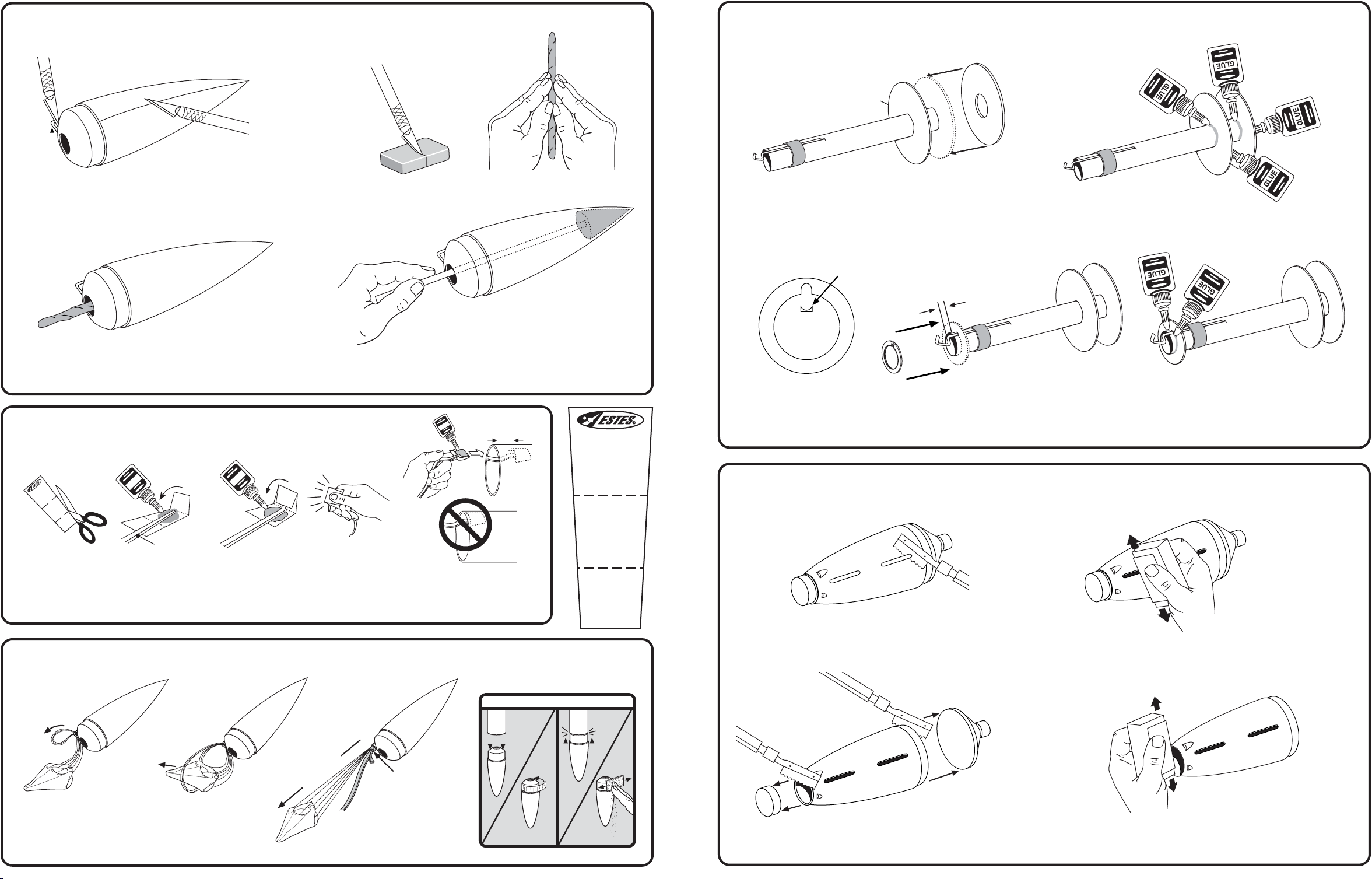
8. PREPARE NOSE CONE AND INSTALL NOSE WEIGHT
G
L
U
E
G
L
U
E
G
L
U
E
2. ATTACH CENTERING RINGS (CONT.)
5 7/8”
(14.9 cm)
MARK
EYELET
CAUTION: DO NOT
CUT OFF EYELET.
A. Using a modeling knife, remove excess flash
from Nose Cone and eyelet.
C. Insert clay “snakes” into Nose Cone, one
at a time.
9. INSTALL SHOCK CORD MOUNT
D
R
O
C
T
K
N
C
U
O
O
3
M
SH
CTION
SE
2
SECTION
1
CTION
SE
3
1
2
SHOCK CORD
B. Cut clay in half and roll into two “snakes”.
C. Slide one large Ring onto Tube, down to 5 7/8” (14.9 cm)
mark. Slide other large Ring onto end of tube.
NOTCH
D. Apply glue fillets to both sides of each ring. Let dry completely.
1/8”
(3 mm)
D. Pack clay “snakes” tightly into tip of Nose Cone using a
scrap piece of balsa or a pencil. Use ALL of the clay.
1.5”
(3.8 cm)
SHOCK CORD
MOUNT
SECTION
3
E. Trim out notch of small Ring
and discard.
F. Slide notched Ring over Engine Hook 1/8”
(3 mm) from end of Engine Tube.
G. Apply glue fillet to both sides of ring.
Let dry completely.
CAUTION: DO NOT
GET GLUE ON
ENGINE HOOK.
3. PREPARE TAIL CONE
3
NO
SECTION
2
A. Cut out Shock
Cord Mount.
B. Apply glue.
Fold forward.
C. Apply glue.
Fold forward.
10. ATTACH PARACHUTE AND SHOCK CORD
A. Pass shroud lines
through eyelet.
6
B. Pass Parachute
through loop.
D. Squeeze tightly
and hold for
one minute.
PULL TIGHT
DOUBLE KNOT
C.
Tie Shock Cord to
Nose Cone using a
double knot.
E. Glue mount 1.5” (3.8 cm)
inside upper Body Tube.
Hold until glue sets. Let
dry.
HELPFUL HINT:
TOO
LOOSE
ADD
MASKING TAPE.
SECTION
IF NOSE CONE/COUPLER FIT IS. . .
TOO
TIGHT
SAND FOR FIT.
1
A. Using a razor saw, carefully remove the nibs that cover
the slots for the Fins.
C. Using a razor saw, carefully cut off ends as shown
and discard.
B. Sand away excess plastic lip flush with surface.
D. Sand excess plastic lip away with sanding block.
3
Page 4

4. INSTALL ENGINE MOUNT AND TAIL CONE
1 1/2”
(3.8 cm
PUSH TAIL CONE
ALL THE WAY IN
)
5. ATTACH LAUNCH LUG (CONT.)
LL
1 1/2”
)
(3.8 cm
A. Apply glue inside Body Tube at
1 1/2” (3.8 cm).
B. Use the Tail Cone to insert and position the
Engine Mount assembly to correct position.
Remove Tail Cone immediately. Let dry.
ENGINE HOOK
REAR VIEW
FIN SLOT
D. Apply tube type plastic cement to the inside edge of Body
Tube and around Centering Ring edge. Slide Tail Cone
into Body Tube. Turn Tail Cone to position Engine Hook
between Fin Slots.
DO NOT CEMENT
TAIL CONE YET!
C. After Engine Mount assembly has
dried, apply a glue fillet around Ring
and Body Tube joint. Let dry.
E. Using a scrap piece of balsa, apply a fillet of tube type plastic
cement to the inside Ring/Tail Cone joint. Let dry completely.
D. Apply glue to Launch Lug, attach on “LL” line as shown.
Be sure to center Launch Lugs on “LL” line so that they
are in alignment with each other. Let dry completely.
6. PREPARE FINS
A. Using fine sandpaper,
sand both sides of laser
cut Fin Sheet.
B. Using a modeling knife,
carefully remove Fins.
7. INSTALL FINS
ROOT EDGES TOUCH OUTSIDE
SURFACE OF TAIL CONE
E. Apply glue fillets to each side of Launch Lug, smooth out with
finger. Let dry completely.
ROUNDED
LEADING EDGE
ROOT EDGES
C. Stack Fins and sand
edges square.
CUT AWAY
VIEW
D. Sand leading edge of Fins to
a slightly round shape. Keep
other edges square.
REAR VIEW
CHECK ALIGNMENT
OF FINS
90°
90°
90°
90°
EDGE
TRAILING
5. ATTACH LAUNCH LUG
SIGHT UP FROM
ENGINE HOOK - MARK
THE BODY TUBE.
ENGINE HOOK
FIN SLOT
A. Place a pencil mark on the body tube
in line with the Engine Hook.
4
DOOR
FRAME
TOP VIEW
LL
DRAW LAUNCH LUG LINE “LL”
FULL LENGTH OF BODY TUBE.
B. Using a door jamb, extend the mark
the entire length of Body Tube.
1”
(25 mm)
1”
(25 mm)
C. Cut Launch Lug into two equal parts.
ROOT EDGE TABS TOUCH ENGINE TUBE
A. Test fit Fins in Slots. B. Sand Fins as needed for a good
fit. Do not sand too much off. Test
fit again. Repeat as needed.
NOTE: FINS MUST
BE ATTACHED
CORRECTLY FOR
STABLE FLIGHT
D. Stand rocket upright as shown, until
glue dries completely.
E. Apply tube type plastic cement fillets to Fin/Tail Cone joints. Smooth out with finger.
Continue until all four Fins are complete. Let dry completely.
C. Apply glue to Fin tabs and push into slots
until Fin is seated flush to Tail Cone.
Repeat for remaining Fins. Let dry.
5
 Loading...