

Page 1
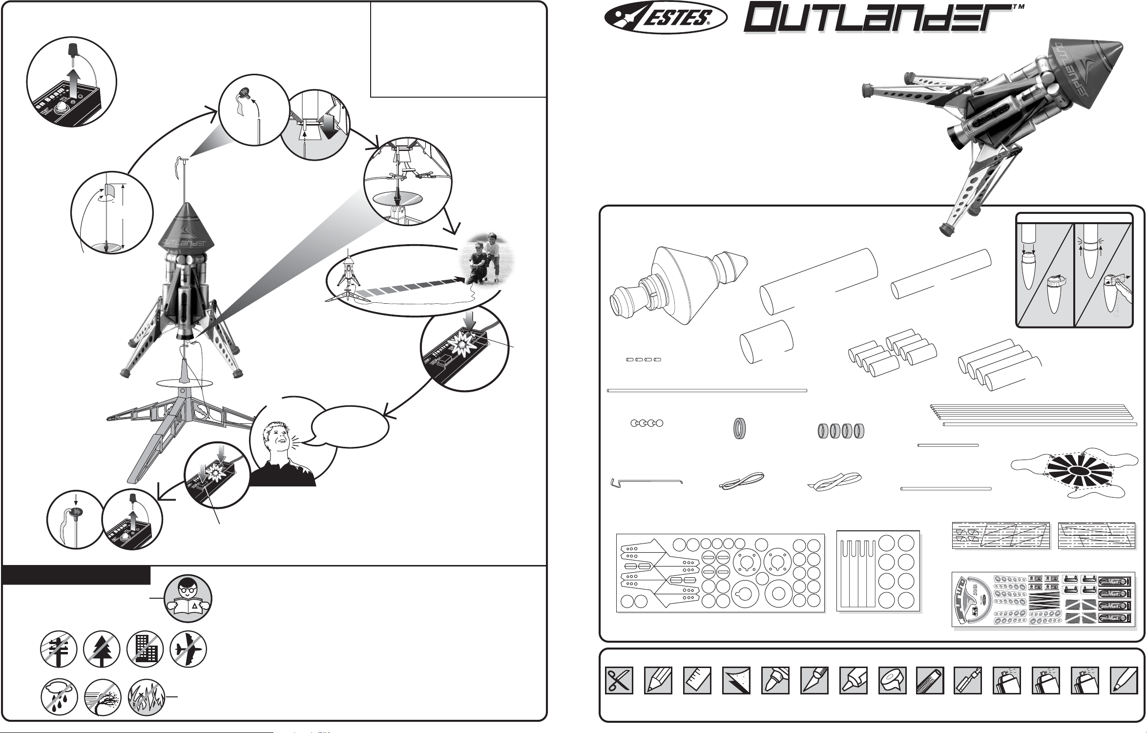
COUNTDOWN AND LAUNCH
8" (20 cm)
LAUNCH SUPPLIES (Sold Separately)
• Porta Pad® II Launch Pad
• Electron Beam® Launch Controller
• Recovery Wadding
• Igniters (with Engines)
• Igniter Plugs (with Engines)
• Recommended Estes® Engines:
B4-2, B6-2, C6-3
www.estesrockets.com
ESTES INDUSTRIES
1295 H Street
Penrose, CO 81240
PRINTED IN CHINA
EST 2110
FLYING MODEL ROCKET KIT INSTRUCTIONS
KEEP FOR FUTURE REFERENCE
KEY ALWAYS OUT UNTIL
FINAL COUNTDOWN!
1...
1...
Masking
Tape
2...
2...
SLIDE ROCKET
DOWN OVER
LAUNCH ROD.
5...
5...
3...
3...
4... 3... 2... 1...
15 FT. (5 M)
4...
4...
INSERT KEY.
PUSH DOWN
AND HOLD.
KEY
ASSEMBLY TIP: Read all instructions
before beginning work on your model. Make
sure you have all parts and supplies.
TEST FIT ALL PARTS TOGETHER
BEFORE APPLYING ANY GLUE!
If any parts don't fit properly, sand as
required for precision assembly.
PARTS
Locate the parts shown below and lay them out on the table in front of
you. DO NOT USE THIS DRAWING TO ASSSEMBLE YOUR ROCKET.
UPPER BODY TUBE
BT-60 (5 11/16")
(30402)
ASCENT MODULE/
NOSE CONE
(60542)
LOWER BODY
LAUNCH LUG (1/4") (4)
(38176)
LAUNCH LUG (9 1/16")
PLASTIC HINGE
BALL STRAND
(60543)
(38185)
GREEN CENTERING RING
AR-2050 (30164-2)
TUBE BT-60 (2")
(30411)
YELLOW FOOT PAD RING (4)
EB-20B (30171-4)
SMALL TANK
BT-20 (1 1/2") (8)
(30319)
WOODEN DOWEL 1/12 x 2
ENGINE MOUNT
TUBE BT-20 (5")
(30310)
(32058)
HELPFUL HINT:
LARGE TANK
WOODEN DOWEL (1/8" x 9") (8)
IF NOSE CONE/COUPLER FIT IS. . .
TOO
LOOSE
ADD
MASKING TAPE.
BT-50 (3") (4)
(30412)
(32054)
TOO
TIGHT
SAND FOR FIT.
PRECAUTIONS
NAR Safety Code
12
LAUNCH
BUTTON
NO DRY GRASS
OR WEEDS
HOLD KEY DOWN AND
PRESS LAUNCH BUTTON
UNTIL LIFT-OFF!
FLYING YOUR ROCKET
Choose a large field (500 ft. [152 m] square) free of dry weeds and
brown grass. The larger the launch area, the better the chance of
recovering your rocket. Football fields and playgrounds are great.
Launch only with little or no wind and good visibility.
Always follow the National Association of Rocketry (NAR)
Safety Code.
MISFIRES
TAKE THE KEY OUT OF THE CONTROLLER. WAIT ONE MINUTE
BEFORE GOING NEAR THE ROCKET! Disconnect the igniter clips and
remove the engine. Take the plug and igniter out of the engine. If the igniter
has burned, it worked but did not ignite the engine because it was not
touching the propellant inside the engine. Put a new igniter all the way
inside the engine without bending it. Push the plug in place. Repeat the
steps under Countdown and Launch.
© 2003 Estes-Cox Corp. All rights reserved.
P/N 60545 (9-03)
ENGINE HOOK
(35021)
SHOCK CORD (1/4" x 24")
(38383)
DIE-CUT CARD
(32436)
ELASTIC CORD
(38224)
DIE-CUT CARD
(32435)
SUPPLIES In addition to the parts included in the kit you will also need:
SCISSORS PENCIL RULER FINE
SANDPAPER
(#400-600 GRIT)
CARPENTER'S
GLUE
MODELING
KNIFE
PLASTIC
CEMENT
MASKING
SILICONE HINGE TUBE (1/8" x 4")
TAPE
(60544)
ROUND
FILE
DIE-CUT BALSA SHEET
RAZOR
SAW
ASSEMBLED
PARACHUTE
18" (45 cm)
(35802)
(32214)
DECAL SHEET (60550)
SPRAY PAINT:
SPRAY
PRIMER
WHITE
BLUE, RED,
SILVER, BLACK
DIE-CUT BALSA SHEET
(32215)
SPRAY
CLEAR
COAT
PAINT
PEN
Page 2

G
LU
E
1
(25 mm)
G
L
U
E
G
L
U
E
PAINTING GUDE
NOTE: In order to paint the model like you see it on the package, it will be necessary to
paint some parts before final assembly. This guide can be used for reference
to paint as you build.
LEGS: Sand, primer and paint.
STRUTS: Midnight Blue
NOSE CONE, NOZZLE: Sand, primer and paint.
NOSE CONE: Midnight Blue
NOZZLE: Silver
INSTALL SHOCK CORD MOUNT
RD
O
C
NT
3
U
CK
N
O
O
IO
M
T
C
SH
E
2
S
N
IO
T
C
E
1
S
N
IO
T
C
E
S
A. Cut out Shock Cord
Mount from WOOD
DOWEL CUTTING
GUIDE.
3
B. Apply glue.
Fold forward.
1
2
SHOCK CORD
3
C. Apply glue.
Fold forward.
D. Squeeze tightly
and hold for one
.
minute
E. Glue mount at least 1” (25 mm) inside
Ascent Module. Hold until glue sets.
Let dry.
MASK OFF
NO PAINT
SILVER
UPPER BODY TUBE: Sand, primer and paint.
UPPER BODY TUBE: Silver (all)
GEAR BOX ASSEMBLY: Sand, primer and paint.
GEAR BOX ASSEMBLY: Midnight Blue (all)
FEET: Bright Red
MASK OFF
NO PAINT
Black
SMALL AND LARGE TANKS: Sand, primer, paint.
SMALL TANKS: Silver (all) LARGE TANKS: Silver (all)
ASCENT MODULE: Sand, primer and paint.
ATTACHING PARACHUTE & SHOCK CORD
A. Form loop in Shroud
Lines and push through
hole in Nose Cone.
B. Pass 'Chute
through loop.
PREPARE PARACHUTE FOR FLIGHT
NOTE: Use Estes
Wadding (EST
A.
Insert 6-7 squares
of loosely crumpled
recovery wadding
into rocket.
302274) Only.
B.
Spike.
C.
Fold.
C.
D.
Pull tight.
Roll.
D.
Tie Shock
Cord on with
double knot.
E.
Wrap lines loosely. Insert ‘Chute,
Shock Cord and Nose Cone into
Body Tube.
ENGINE PREP
Midnight BlueBright Red
Separate igniter and igniter plug.
NOTE: On areas where surfaces are to be glued,
TIP MUST
TOUCH
PROPELLANT!
mask off prior to painting or remove paint
before gluing.
2 11
PREPARE YOUR ENGINE
ONLY WHEN YOU ARE
OUTSIDE AT THE LAUNCH SITE
PREPARING TO LAUNCH!
Hold engine
upright, drop in
igniter. Igniter must
touch propellant.
Insert igniter
plug.
Firmly push all
the way in.
Bend igniter
wires back.
Insert engine.
Page 3

20. ATTACH ASCENT MODULE
A. Apply plastic
cement to
body tube.
B. Align launch lug with
hole and slide Ascent
Module over body tube.
TOP OF ASCENT
MODULE SHOULD
BE FLUSH WITH TOP
OF LAUNCH LUG
1. CUT WOOD DOWELS
Refer to the Wooden Dowel Cutting Guide and carefully cut all the dowels needed for the leg assemblies. Lightly sand ends smooth.
2. PREPARE HINGE ASSEMBLY
(Four needed for assembly)
A. Separate plastic
Hinge Balls (4)
from strand.
1"
(25 m
)
m
B. Cut Silicone Hinge
Tube into four equal
pieces of 1" (25.4 mm).
C. Insert a hinge ball half
way into each of the
four Silicon Hinge
Tubes.
D. Collect four 1 3/4" (4.4 cm) wood dowels
(Section "D" of template). Insert one into
each hinge until it touches hinge ball.
FINISHING YOUR ROCKET
If you have chosen not to paint your parts before final assembly, now you can sand, prime and paint. The easiest way to get good results is to
spray paint the entire rocket all one color. You may also paint the Ascent Module a different color than the body. When completely dry, proceed
to decal placement.
If you have already painted your parts prior to assembly, proceed to decal placement.
DECAL PLACEMENT
Remove decals from backing one at a time and refer to the drawing below or to the
picture on the front of the package.
A (wrap)
B
C (four)
D (four)
E (four)
F
D
G
C
E
3. LANDING FOOT ASSEMBLY
(Four needed for assembly)
A. Remove die-cut discs shown in gray
from card. Remove the outside nubs
with sandpaper.
4. LEG ASSEMBLY
(Four needed for assembly)
B. Carefully remove the die-cut pieces
using a modeling knife.
A. Sand smooth the die-cut balsa sheet.
YELLOW FOOT
PAD RING
B. Glue the discs and yellow Foot Pad
Ring together as shown.
TOP
C. Collect the four 6 3/4" (17.1 cm) dowels (Section "C" of
template). Match the angled cut to the foot end. Glue as
shown. Repeat for all four legs and let dry.
COMPLETED FOOT PAD
C. Repeat for other three. Let dry.
FOOT
ANGLE CUT
10
F (four)
G (eight-right and left)
H (eight-right and left)
MATCH ANGLE
D. Collect the four 2 3/16" (8.1 cm) dowels with angle cuts
at both ends (Section "A" of template). Glue as shown.
H
Make sure angles match. Repeat for all four legs. Let dry.
E. Remove Support Struts
from die-cut card. Sand
the nubs smooth.
F. Glue Support Strut to assembly as
shown. Make sure strut is flush with
ends of dowel. Repeat for all four
legs. Let dry.
A
B
G. Collect the four 5 5/8" (14.3 cm) dowels (section "B" of template).
Glue as shown. Make sure dowel is flush with end of leg and
butts up to end of top dowel. Repeat for all four legs. Let dry.
H. Glue remaining struts to opposite sides
for all four leg assemblies. Let dry.
…Continued Page 4
3
Page 4
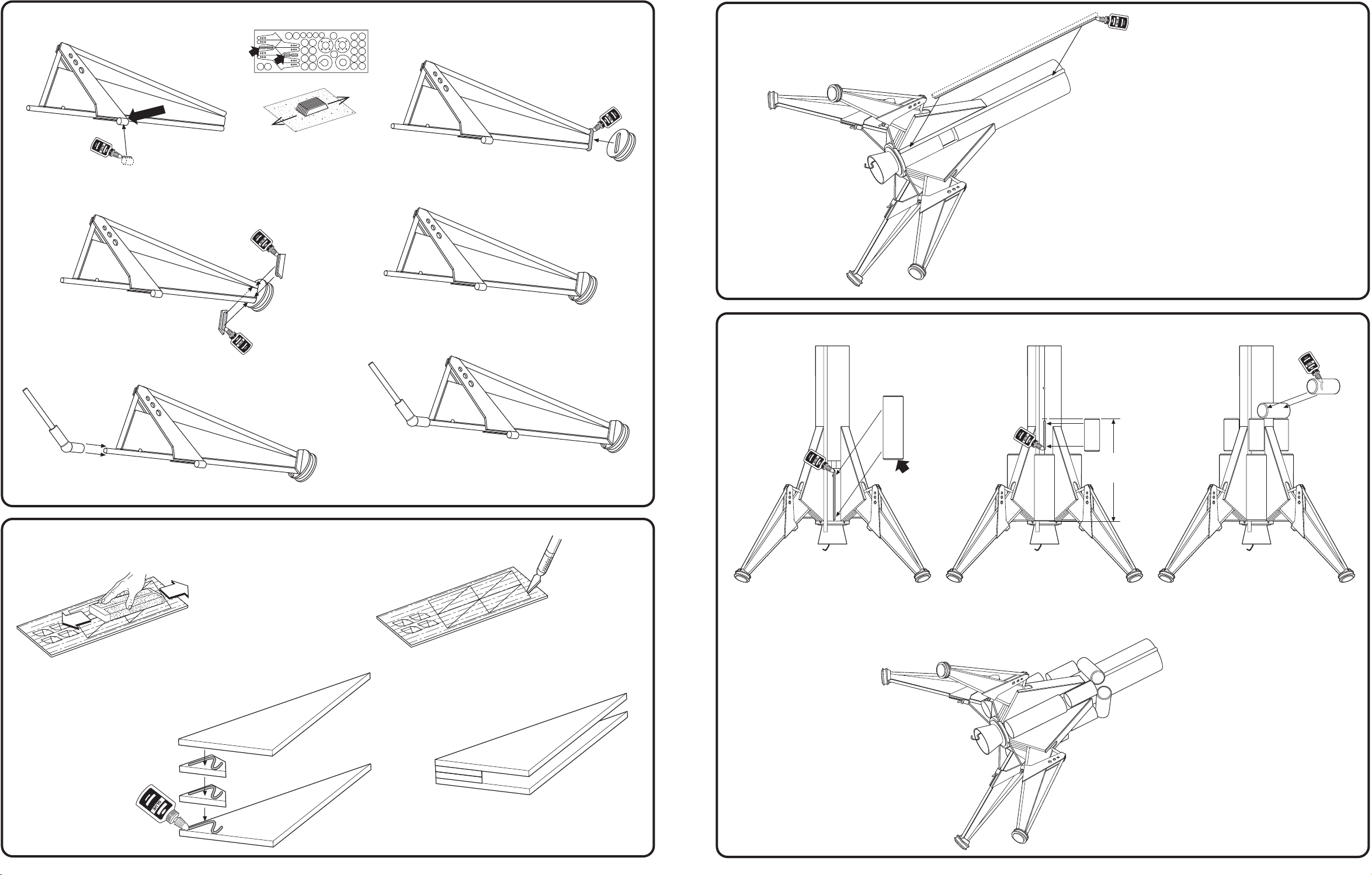
4. LEG ASSEMBLY (continued)
FLUSH
I. Glue 1/4" (6.4 mm) Launch Lug to inside leg
dowel using Carpenter's Glue. Repeat for
all four legs. Let dry.
J. Remove and sand smooth foot
supports from die-cut card.
K. Glue foot to leg using Carpenter's Glue.
Repeat for other three legs. Let dry.
18. ATTACH LAUNCH LUG
A. Apply glue bead to Launch Lug.
B. Attach Launch Lug to body
tubes centering on "LL" line.
Let dry.
L. Glue foot supports to leg using
Carpenter's Glue. Repeat for
other three legs. Let dry.
M. Insert hinge tube over dowel as
shown until dowel touches hinge ball.
Repeat for other three legs.
5. PREPARE GEAR HOUSING COVERS
(Four needed for assembly)
COMPLETED LEG ASSEMBLY
COMPLETED HINGE/LEG ASSEMBLY
NOTE: You may want to primer, sand, and paint the
Leg Assembly at this time. See PAINTING
GUIDE (page 2).
19. ATTACH LARGE AND SMALL TANKS
FLUSH WITH
LOWER BODY
TUBE
A. Apply glue bead to Lower Body Tube
on line marked "T" for Tank. Attach
Large Tank. Repeat for other three
Large Tanks. Let dry.
B. Apply glue bead to Upper Body Tube
on line marked "T" for Tank. Attach
Small Tank. Repeat for other three
Small Tanks. Let dry.
TOP OF TANK AT
3 3/8"
(8.6 cm)
MARK
C. Apply glue bead to center of Small
Tank. Attach Small Tank-center over
Gear Housing. Repeat for other three
Small Tanks. Let dry.
B. Remove the gear housing pieces
A. Sand smooth the die-cut balsa sheet.
C. Glue Support
Spacers and Gear
Housing Covers
together with
Carpenter's Glue.
Repeat for other
three. Let dry.
4 9
from the die cut-balsa using a
modeling knife.
COMPLETED ASSEMBLY
Set aside to let dry.
COMPLETED
ASSEMBLY
Page 5
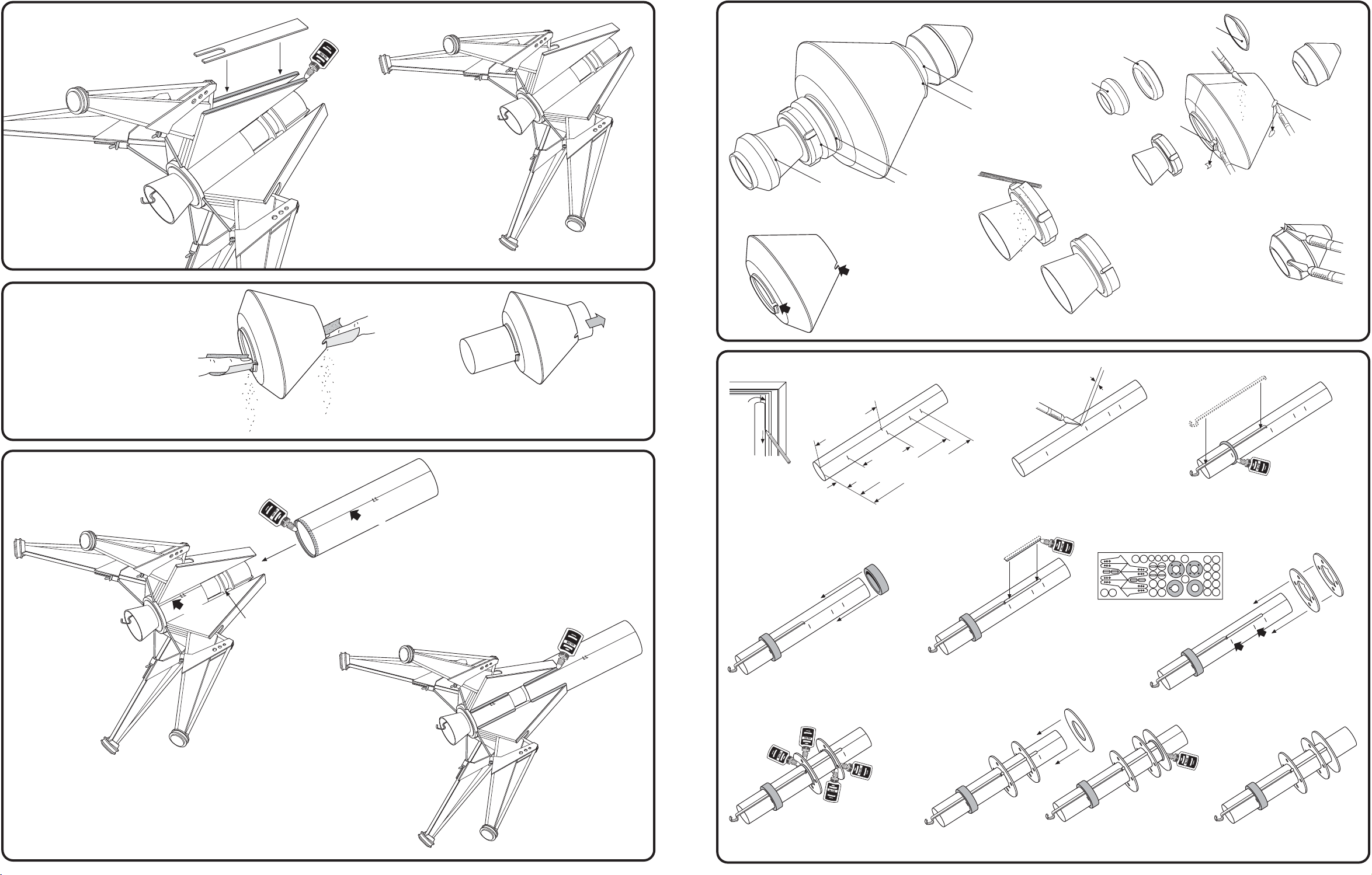
15. ATTACH GEAR HOUSING COVERS
A. Apply Carpenter's Glue
to Gear Housing as
shown. Attach cover.
B. Repeat for other three
legs. Let dry.
16. PREPARE ASCENT MODULE
COMPLETED
ASSEMBLY
6. CUT & TRIM PLASTICS PARTS
CUT
CUT
A. Using a razor saw, cut Ascent
Module/Nose Cone where shown.
C. Sand until flush.
CUT
CUT
CUT
D. Using a round file,
carefully clean four
slots out of Engine
Nozzle until flush.
DISCARD
DISCARD
COMPLETED
NOZZLE
DISCARD
LAUNCH
LUG
HOLE
LAUNCH
LUG
HOLE
B. Trim flash using a modeling knife or
sandpaper. Remove the two nibs as
shown for the launch lug holes.
E. Using a modeling knife
and round file, clean out
hole in Nose Cone for
Shock Cord and remove
excess flash.
NOTE: You may want to primer, sand, and paint the
Nozzle and Nose Cone at this time. Don't finish the
Ascent Module yet. See PAINTING GUIDE (page 2).
A. Sand Ascent Module openings
until Upper Body Tube fits
smoothly.
17. INSERT UPPER BODY TUBE
A. Apply glue ring just
inside Upper Body
Tube as shown.
ALIGN
LOWER
CENTERING
RIING
B. Test fit Ascent Module
openings with Upper
Body Tube.
NOTE: You may want to primer, sand, and paint the Ascent
Module at this time. See PAINTING GUIDE (page 2).
ALIGN
B. Slide tube over lower assembly
until it is flush with Lower
Centering Ring. Align launch
lug lines. Let Dry.
7. ASSEMBLE ENGINE MOUNT
DOOR
FRAME
(6.4 cm)
2 1/2"
(6.8 cm)
(9 cm)
3 9/16"
2 11/16"
(2.5 cm)
1"
A. First draw line full length of Engine Mount
Tube using door frame. Measure and mark
tube using a pencil as shown.
D. Slide the green centering
ring down the tube to the
1" (2.5 cm) mark.
3 15/16"
E. Glue the small 2" wooden dowel (supplied
pre-cut) to tube straight on line and flush
with end of Engiine Hook. Let dry.
(10 cm)
1/8"
B. Make a 1/8" (3 mm) slit at
the 2 1/2" (6.4 cm) mark.
F. Remove centering rings
from die-cut sheet. Sand
any nubs.
C. Insert Engine Hook into slit as shown.
Apply bead of glue around tube just
above the 1" (2.5 cm) mark.
G. Slide the two Centering Rings
with holes down to the 2 11/16"
(6.8 cm) and 3 9/16" (9 cm)
marks.
C. Apply glue fillets
to Gear Housing
and Body Tube
joints. Smooth
with finger.
8
COMPLETED
ASSEMBLY
H. Apply glue fillets to both sides
of Centering Rings. Let dry.
I. Slide Centering RIng with no notch over tube up to the
3 15/16" (10 cm) mark. Apply glue filles to both sides.
COMPLETED MOUNT
Set aside to dry.
5
Page 6
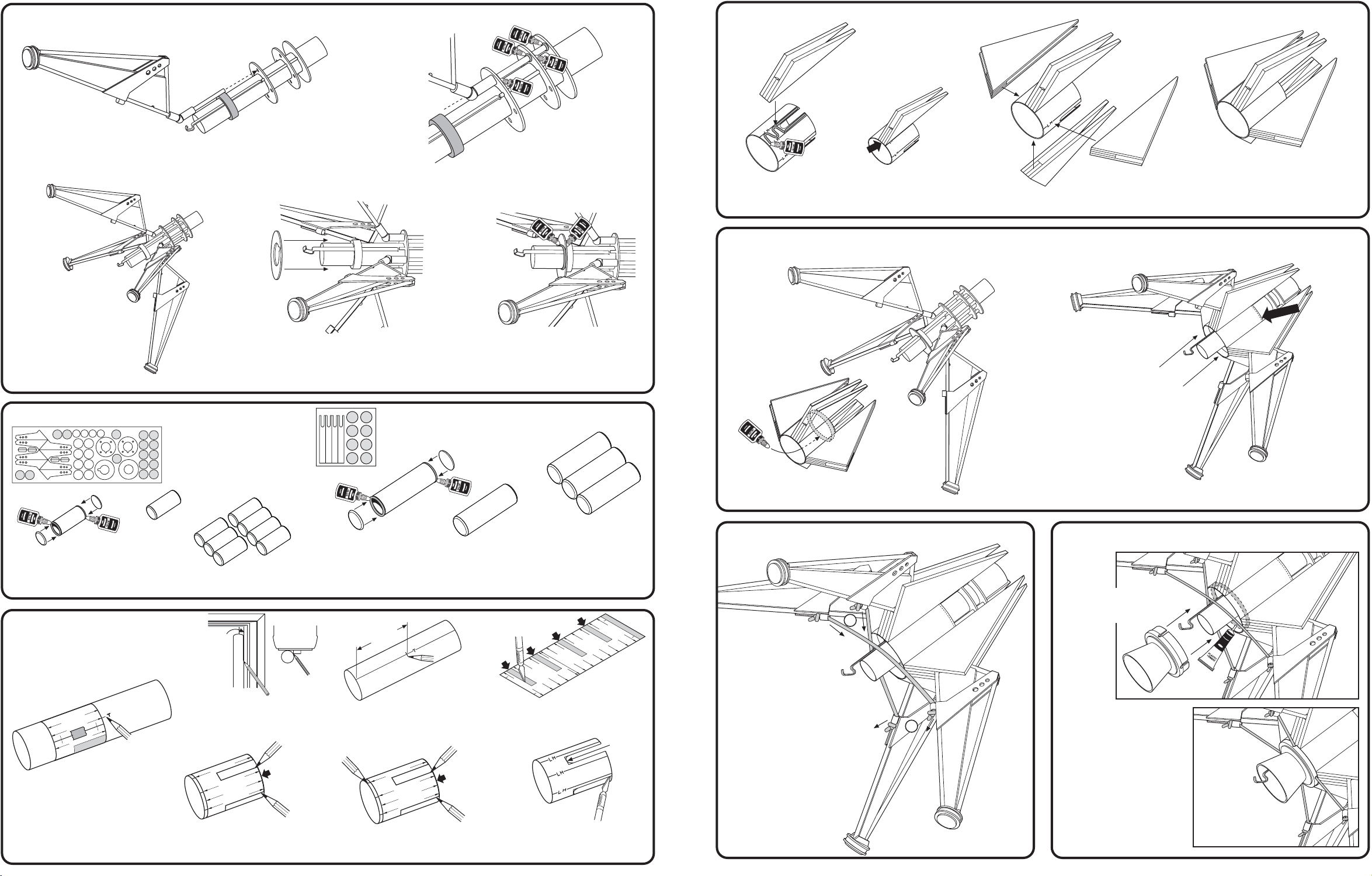
8. ATTACH LEG HINGE & ENGINE MOUNT ASSEMBLY
L
A
R
G
E
T
A
N
K
L
A
R
G
E
T
A
N
K
L
A
R
G
E
T
A
N
K
L
A
R
G
E
T
A
N
K
C
U
T
O
U
T
C
U
T
O
U
T
C
U
T
O
U
T
C
U
T
O
U
T
L
E
G
H
O
U
S
I
N
G
L
E
G
H
O
U
S
I
N
G
L
E
G
H
O
U
S
I
N
G
L
E
G
H
O
U
S
I
N
G
L
E
G
H
O
U
S
I
N
G
L
E
G
H
O
U
S
I
N
G
L
E
G
H
O
U
S
IN
G
L
E
G
H
O
U
S
I
N
G
L
A
U
N
C
H
L
U
G
O
V
E
R
L
A
P
T
A
B
L
E
G
H
O
U
S
IN
G
C
U
T
O
U
T
L
A
R
G
E
T
A
N
K
L
E
G
H
O
U
S
IN
G
11. ASSEMBLE GEAR HOUSING
C. Repeat for other
three legs. Let dry.
A. After Engine Mount Assembly has
dried, slide Leg Hinge Assembly
into place as shown.
D. Slide Centering Ring with notch over Engine
Mount Tube, aligning notch with Engine Hook,
until it butts up to Green Adapter Ring.
B. Apply gllue fillets. Let dry.
E. Apply glue fillets. Let dry.
FRONT
REAR
REAR
FLUSH
A. Apply glue to body tube as shown. Attach Gear
Housing Asssembly. Make sure it is flush with
rear of tube and aligned with slots.
B. Repeat for other three.
Allow assembly to dry.
12. ATTACHING GEAR HOUSING TO LANDING GEAR
FRONT
REAR
COMPLETED ASSEMBLY
NOTE: You may want to sand, primer, and paint
the Gear Housing Assembly at this time.
See PAINTING GUIDE (page 2).
FLUSH
FRONT
9. PREPARE TANK ASSEMBLIES
SMALL TANKS:
COMPLETED
TANK
A. Remove the 16 small
discs from die-cut sheet.
Glue a disc to each end
of small tube as shown.
B. Repeat for other seven
tanks. Let dry.
10. MARK BODY TUBES
NOTE: You may want to sand, primer,
and paint the Upper Body
Tube prior to marking. See
PAINTING GUIDE (page 2).
A. Cut out Tube Marking Guide and
wrap around UPPER BODY
TUBE. Tape to secure. Mark all
LARGE TANK lines and label
"T". Mark LAUNCH LUG line
and label "LL". Carefully remove
Tube Marking Guide and save.
6
D. Wrap around and tape to
LOWER BODY TUBE. Draw
an outline for the cutouts.
LARGE TANKS:
C. Remove the eight large
discs from die-cut sheet.
Glue a disc to each end
of large tube as shown.
DOOR
FRAME
TOP
VIEW
B. Extend all lines using door frame. Mark tank
lines ("T") at 3 3/8" (8.6 cm).
LEG HOUSING
LEG HOUSING
LARGE TANK
H
G
E
L
U
O
FLUSH
G
IN
S
E. Mark LAUNCH LUG line and label "LL".
Mark all eight LEG HOUSING lines and
label "LH". Extend all lines using door frame.
3 3/8"
(8.6 cm
LEG HOUSING
)
LEG HOUSING
LARGE TANK
H
G
E
L
D. Repeat for other
COMPLETED TANK
NOTE: You may want to sand, primer, and paint
the Small and Large Tanks at this time.
See PAINTING GUIDE (page 2).
C. Cut out tube slot locations
on marking guide.
FLUSH
G
IN
S
U
O
F. Using a modeling knife
& sandpaper, cut out
and smooth slots.
three. Let dry.
ROUND
OUT THE
ENDS
B. Slide assembly up and
flush with centering
ring. Let dry.
A. After Gear Housing Assembly is
dry, apply glue ring inside tube as
shown.
13. ATTACH SHOCK ABSORBING CORDS 14. ATTACH ENGINE NOZZLE
NOTE: Make sure you
don't get cement
on cords!
A. Apply plastic cement ring
inside Gear Housing
Assembly Tube as shown.
B. Carefully push nozzle
over engine hook and
engine tube. Fit cords
into notches.
C. Push Engine Nozzle all the
way into Lower Body Tube.
Make sure cords move
freely in notches. Let dry.
COMPLETED
ASSEMBLY
A. Cut elastic cord into
two equal pieces.
B. Tie a double knot at
one end of each cord.
C. Thread cords through lugs
as shown.
D. Thread cords through
opposite lugs, pull tight,
and tie double knots.
E. Trim excess.
C
D
7
Page 7
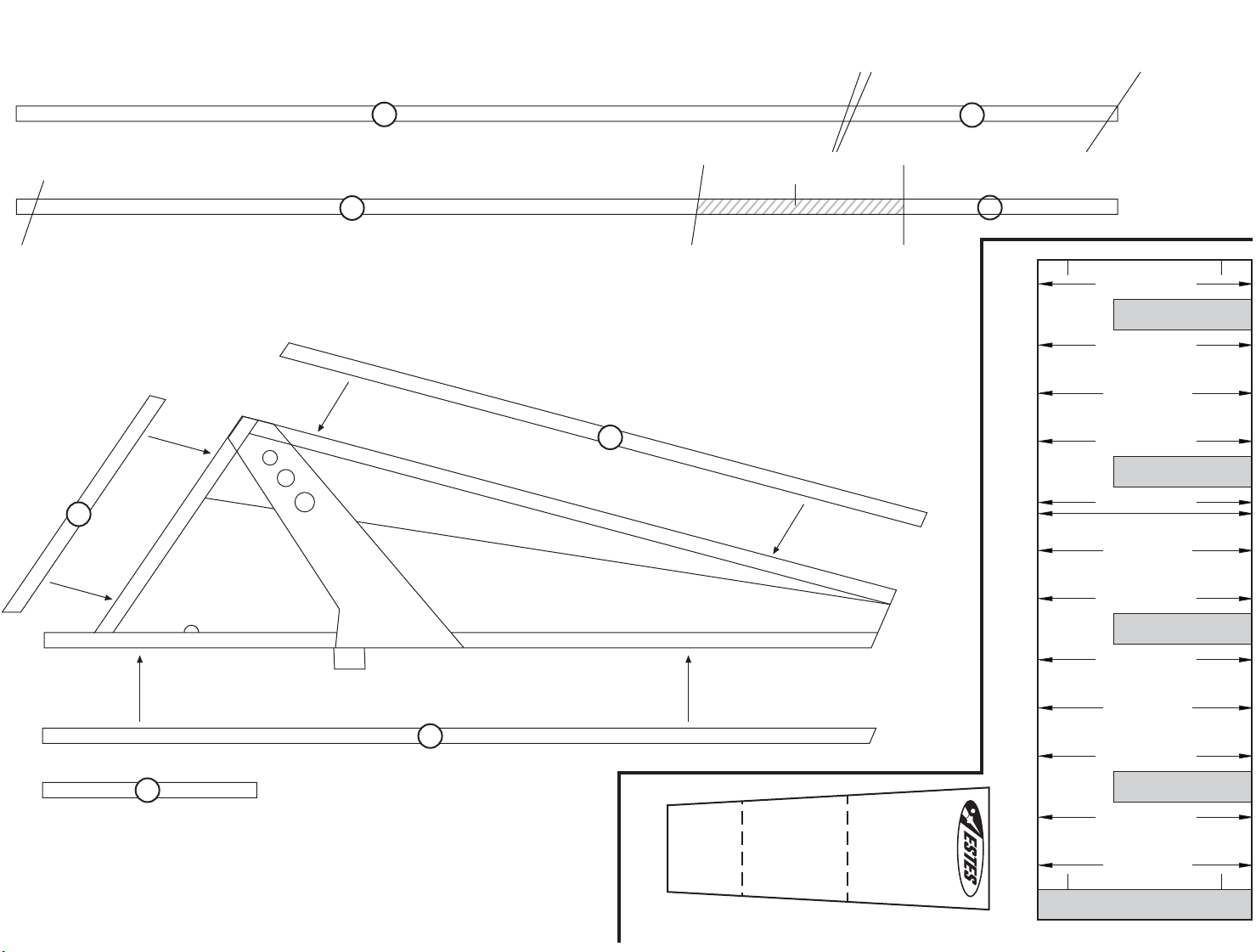
1/8" x 9" WOOD DOWEL CUTTING GUIDE
PATTERN 1
CUT 4 DOWELS TO PATTERN 1
C
A
PATTERN 2
CUT 4 DOWELS TO PATTERN 2
B
DISCARD THIS SECTION
NOTE: Lay dowels over pattern and carefully cut with razor saw. Lightly sand ends smooth. Cut the exact length and angles
shown above.
Drawing below shows the placement of the dowels on the leg assemblies. You will build four leg assemblies.
B
A
D
LEG HOUSING
CUT OUT
LEG HOUSING
LARGE TANK
LEG HOUSING
CUT OUT
LEG HOUSING
LAUNCH LUG
LARGE TANK
LEG HOUSING
CUT OUT
D
FITS INTO HINGE (STEP 2)
© 2003 Estes-Cox Corp.
All rights reserved. P/N 60546 (9-03)
C
PRINTED IN CHINA
SHOCK CORD
SECTION
1
SECTION
2
SECTION
3
MOUNT
SHOCK CORD MOUNT
LEG HOUSING
TUBE MARKING GUIDE
LARGE TANK
LEG HOUSING
CUT OUT
LEG HOUSING
LARGE TANK
OVERLAP TAB
 Loading...