

Page 1
www.estesrockets.com
ESTES® INDUSTRIES
1295 H Street
Penrose, CO 81240
PRINTED IN CHINA
EST 1247/2053
FLYING MODEL ROCKET KIT INSTRUCTIONS
KEEP FOR FUTURE REFERENCE.
ASSEMBLY TIP:
Read all instructions before beginning
work on your model. Make sure you have
all parts and supplies.
PARTS:
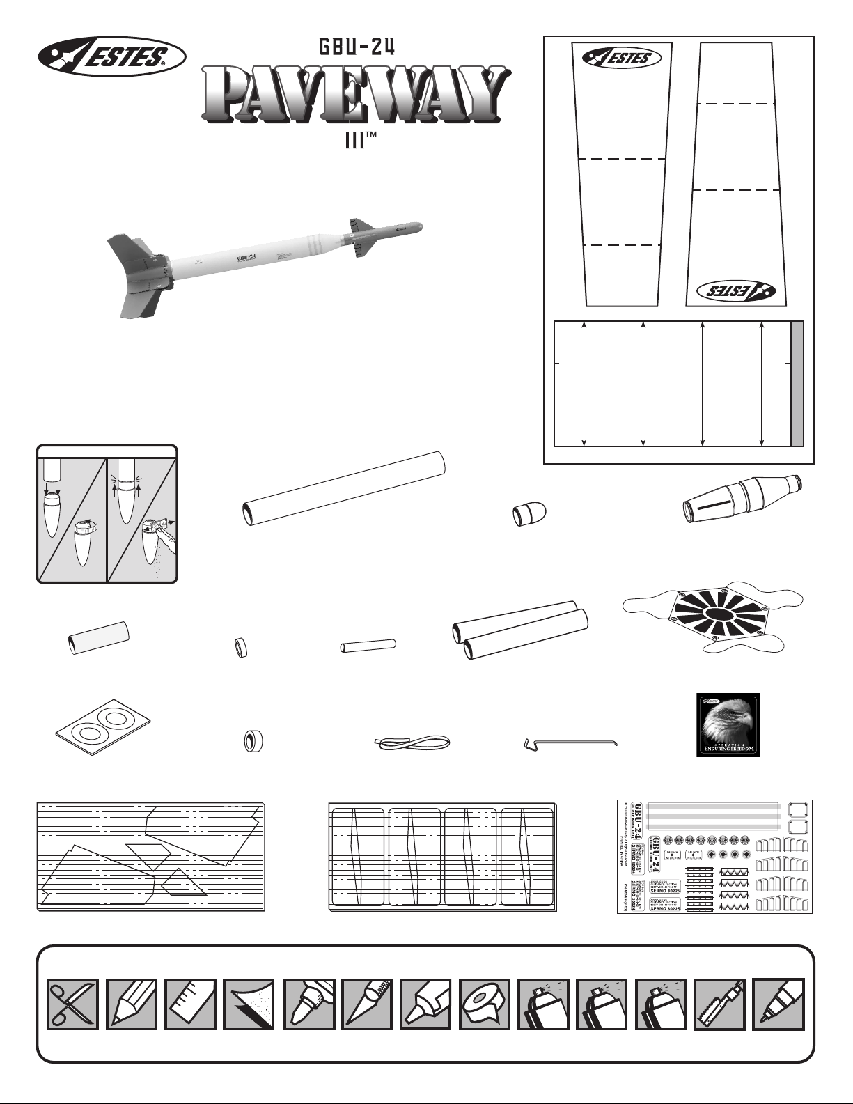
Locate the parts shown below and lay them out on the table in front of you. DO NOT
USE THIS DRAWING TO ASSEMBLE YOUR ROCKET.
HELPFUL HINT: IF NOSE CONE/COUPLER FIT IS. . .
TOO
LOOSE
TOO
TIGHT
TEST-FIT ALL PARTS TOGETHER
BEFORE APPLYING ANY GLUE!
If any parts don’t fit properly, sand as required
for precision assembly.
SHOCK CORD
MOUNT
SECTION
SECTION
SECTION
FIN
MATCH LINES
3
2
1
UPPER TUBE MARKING GUIDE
FIN
FIN
GBU-24 PAVEWAYIII EST 2053
1
2
3
SECTION
SECTION
SECTION
MOUNT
FIN
TUBE MARKING GUIDE
SHOCK CORD
ADD
MASKING TAPE.
SAND FOR FIT.
Yellow Spacer Tool (1)
(35003)
Centering Ring Card (1)
(30126)
Die Cut Balsa Sheet (2)
(32218)
Mylar Retainer
Ring (1)
(30168)
Green Engine
Block (1)
(30162-2)
Body Tube BT-55 (1)
(30374)
Launch Lug (1)
(38178)
Shock Cord (1)
Die Cut Balsa Sheet (1)
1/8" x 18"
(38374)
(32219)
Nose Cone (1)
(60567)
Body Tube BT-20 (2)
(30329)
Engine Hook (1)
(35021)
Plastic Tail Cone and
Adapter (1)
(60568)
Assembled 12” (30 cm) Parachute
(35801)
Operation Enduring Freedom
sticker (1)
(60586)
Decal Sheet (1)
(60569)
SUPPLIES
SCISSORS PENCIL
In addition to the parts included in the kit you will also need:
RULER
FINE
SAND PAPER
(#400-600 GRIT)
CARPENTER’S
GLUE
MODELING
KNIFE
PLASTIC
CEMENT
MASKING
TAPE
SPRAY
PRIMER
WHITE
SPRAY PAINT:
WHITE, OLIVE
DRAB, RED
SPRAY
DULL
COAT
RAZOR SAW
SILVER PAINT
PEN
Page 2
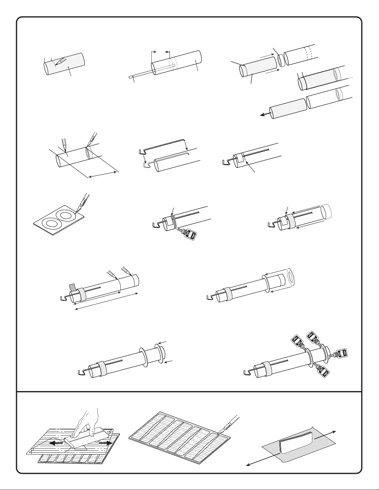
1. ASSEMBLING ENGINE MOUNT
G
LU
E
GLUE
GLUE
GLUE
G
LUE
A. Measure and mark Yellow
Sp acer Tool.
1/2”
(13 mm)
Yellow Spacer
Tool
D. Mark engine mount tube at 1" (25 mm) and
2 1/4" (57 mm) from rear end. Cut 1/8" (3 mm)
slit at 2 1/4" (57 mm) mark.
1"
(25 mm)
2 1/4"
(57 mm)
B. Use scrap balsa to smear glue 2" (51 mm)
Scrap Balsa
inside engine mount tube.
2"
(51 mm)
Engine mount
E. Position Engine
Hook.
Tube
Green Engine
Block
Mark
Yellow Spacer Tool
F. Temporarily tape hook
into place.
I" mark
(25 mm)
C. Push engine block into BT-20 engine mount
tube with spacer tool up to mark. Remove
spacer tool.
1/2"
(13 mm)
Rear
Remove
Immediately
G. Carefully remove rings
from card.
J. Place a pencil mark at 2 1/2" (64 mm) and
4 7/8 (124 mm) from end of engine mount.
Remove tape.
Rear
2 1/2 (64 mm)
4 7/8 (124 mm)
L. Slide a centering ring down to
the 4 7/8" (124 mm) mark.
H. Apply glue above the
1" (25 mm) line.
1" mark
(25 mm)
K. Slide a centering ring down to
the 2 1/2" (64 mm) mark.
I. Slide mylar retainer ring onto engine
mount tube up to 1" (25 mm) mark. Let
dry.
M. Apply glue fillets to both sides of
each centering ring. Let dry.
1" mark
(25 mm)
2. PREPARING FINS
A. Fine sand balsa sheets. B. Carefully cut parts free with knife.
C. Stack like pieces and sand edges
smooth. Leave the edges square,
do not round them.
Page 3
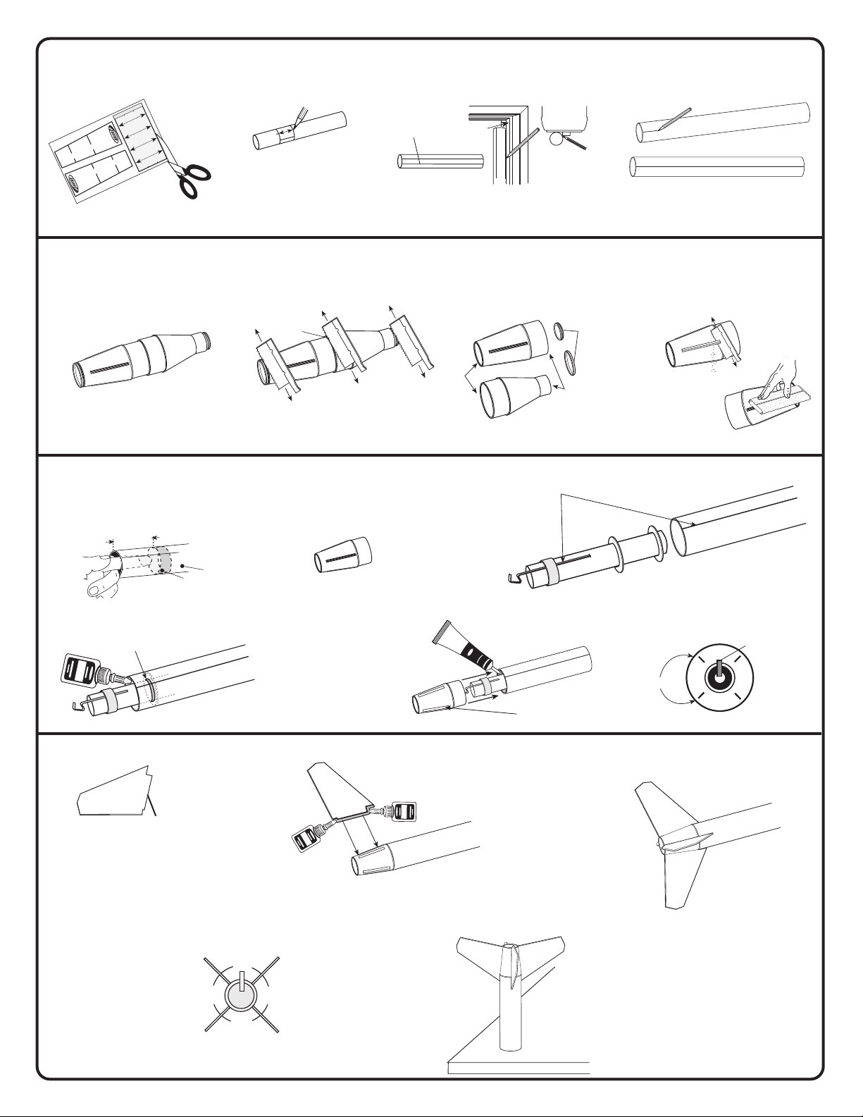
3. MARKING BODY TUBES
90˚
90˚
90˚
90˚
GLUE
GLUE
GLUE
A. Cut out tube marking
guide.
B. Wrap tube marking guide around
upper body and mark four places.
C. Extend all lines entire length
of tube.
D. Place a pencil mark on the
larger tube for launch lug "LL".
F
I
N
T
U
B
E
M
A
R
K
IN
SHOCK CORD
G
G
U
AYIII EST 2053
ID
E
IDE
U
MOUNT
F
IN
G
SECTION
SECTION
SECTION
2
1
3
N
TIO
C
E
S
MOUNT
SHOCK CORD
ARKING
3
M
F
IN
1
N
2
N
TIO
EC
S
GBU-24 PAVEW
FIN
M
A
UPPER TUBE
T
TIO
C
H
L
C
IN
E
S
E
S
BT-20
Upper Body Tube
Fin lines
Upper Body Tube
4. PREPARE TAIL CONE AND ADAPTER
A. Tail Cone and Adapter B. Using a razor saw, carefully cut off
ends and cut in half.
Cut in half.
Cut off.
Cut off.
5. ASSEMBLING ENGINE MOUNT AND TAIL CONE
A. Use finger to smear glue 2 3/4" (70 mm)
inside rear of body tube.
DO NOT CEMENT
TAIL CONE YET!
Top view
Door
Frame
Main Body Tube BT-55 (1)
"LL"
Extend Launch Lug line
with pencil.
C. Sand edges smooth. D. Carefully saw off nibs. Sand away
excess plastic lip flush with surface.
DISCARD
Sand edges smooth.
B. Engine hook must line up with
launch lug "LL" line.
2 3/4”
(70 mm)
MAIN BODY TUBE
"LL"
Body
Tube
Glue
D. Apply a glue fillet around ring and
body tube joint. Let dry.
E. Apply plastic cement around
"LL"
6. ASSEMBLING LOWER FINS
A. Test fit fin tabs in slots.
Sand as needed for
proper fit.
Ta b
NOTE: Fin
shape and
tab location.
C. Check alignment of fins as
shown. Allow glue to set.
inside of body tube. Align
Launch Lug line between
fin slots on tail cone. Push
tail cone into body
completely. Let dry.
CEMENT
PLASTIC
"LL"
Fin Slot
B. Apply carpenter's glue to fin and tab
edge. Push fin into tail cone. Let dry.
Continue to assemble remaining fins.
Let dry.
D. Stand rocket on flat table
until glue dries completely.
"LL"
C. Insert engine mount inside body tube
and push into place with tail cone.
Remove tail cone immediately. Let dry.
Engine Hook
Fin Slots
Rear View
NOTE: Fins must be attached
correctly for stable flight.
Fins should project
straight from the body.
Page 4
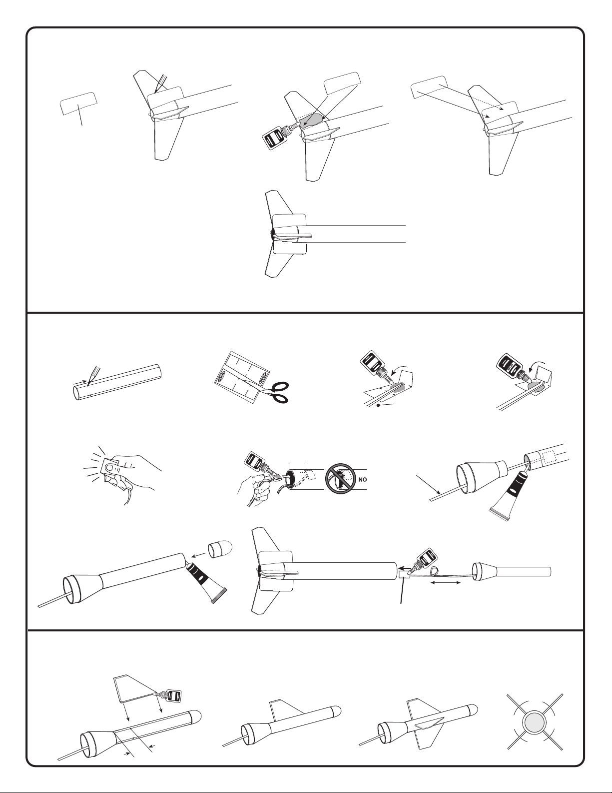
ASSEMBLING FIN REINFORCEMENTS
GLUE
GLUE
GLUE
GLUEGLUE
GLUE
90˚
90˚
90˚
Fin Reinforcement
A. Align reinforcement with fin.
Mark edge with pencil.
D. Repeat steps to apply
reinforcements to remaining
3 fins. Let dry.
B. Smear glue on fin as shown
line. Apply reinforcement.
COMPLETED FIN ASSEMBLEY
7. ATTACHING SHOCK CORD & ASSEMBLING UPPER BODY TUBE
A. Mark body tube 3/4" (19 mm)
from end on each fin line.
3/4"
(19 mm)
B. Cut out shock cord mount.
SECTION
SECTION
1
SECTION
2
SHOCK CORD
D
R
O
T
C
N
K
U
C
O
O
M
H
S
MOUNT
3
3
2
SECTION
1
SECTION
SECTION
C. Apply glue. Fold forward.
1
2
3
Shock cord
C. Repeat steps A & B and apply
reinforcement to other side
of fin.
NOTE: Fins must be
attached correctly for stable
flight.
D. Apply glue. Fold forward.
3
E. Squeeze tightly and hold
for one minute.
H. Apply Plastic cement to forward
end of tube and insert nose
cone. Let dry.
8. ASSEMBLING UPPER FINS
A. Apply glue to edge of fin as shown and attach to
pencil line at the 3/4" (19 mm) mark. Let dry.
G. Put a bead of plastic cement in
the rear of body tube. Insert
adapter. Let dry.
P
C
E
J. Cut out second shock cord mount. Glue
and fold as before. Apply glue to shock
cord mount and then insert it into the large
body tube. Press firmly. Let dry.
3" (76 mm)
PLASTIC
CEMENT
F. Apply glue to shock cord mount and
place inside end of upper body tube.
Press firmly. Let dry.
1”
(25 mm)
I. Tie loop 3" (76 mm) from
second shock cord mount.
THREAD SHOCK
CORD THROUGH
ADAPTER.
Second shock cord mount.
B. Assemble remaining fins. Let dry. C. Complete assembly. D. Fins must be straight.
LA
S
TIC
M
E
N
T
3/4" (19 mm)
Page 5
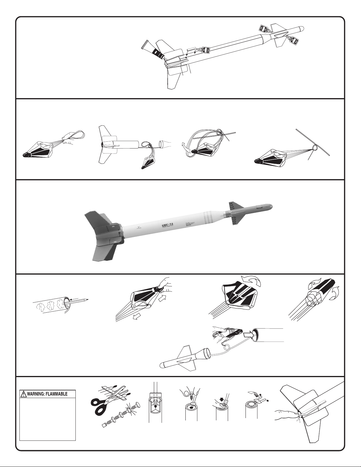
9. ATTACHING LAUNCH LUG AND APPLY FILLETS
GLUEGLUE
GLUEGLUE
GLUEGLUE
A. Measure 3/4" (19 mm) from end of body tube and
mark. Glue launch lug on the launch lug line "LL".
C
P
B. Apply glue fillets to all launch lug and fin/body
joints. Smooth with finger. Let dry.
C. Apply fillets to main fins/ body tube using plastic
cement. Smooth with finger. Let dry.
E
L
M
A
E
S
N
T
T
IC
C.
3/4"
(19 mm)
10. ATTACHING PARACHUTE
A. Loop shroud lines.
B. Push through shock cord loop. C. Loop parachute through shroud lines.
B.
A.
"LL"
D. Pull tightly.
Shock Cord loop.
Shock Cord loop.
PAINT SCHEME
First spray rocket with white primer, let dry
and sand. Repeat until rocket is smooth.
Follow the paint scheme on the package.
ROCKET PREFLIGHT
A. Insert four squares of loosely crumpled
recovery wadding into rocket body tube.
NOTE: Use Estes wadding (EST 302274) only.
E. Wrap lines loosely. Insert
parachute, shock cord,
then upper assembly.
When paint is dry, peel decals one at a time
from backing sheets and apply where shown.
Rub down to remove bubbles.
C. Fold. D. Roll.B. Spike.
*Optional - Spray a dull coat over
the entire rocket when complete.
ENGINE PREP
To avoid serious injury,
read instructions & NAR
Safety Code included with
engines.
PREPARE YOUR ENGINE
ONLY WHEN YOU ARE
OUTSIDE AT THE LAUNCH
SITE PREPARING TO LAUNCH!
If you do not use your prepared
engine, remove the igniter before
storing your engine.
A.
B. Tip must touch
propellant.
E. F. Insert engine.D.C.
Page 6
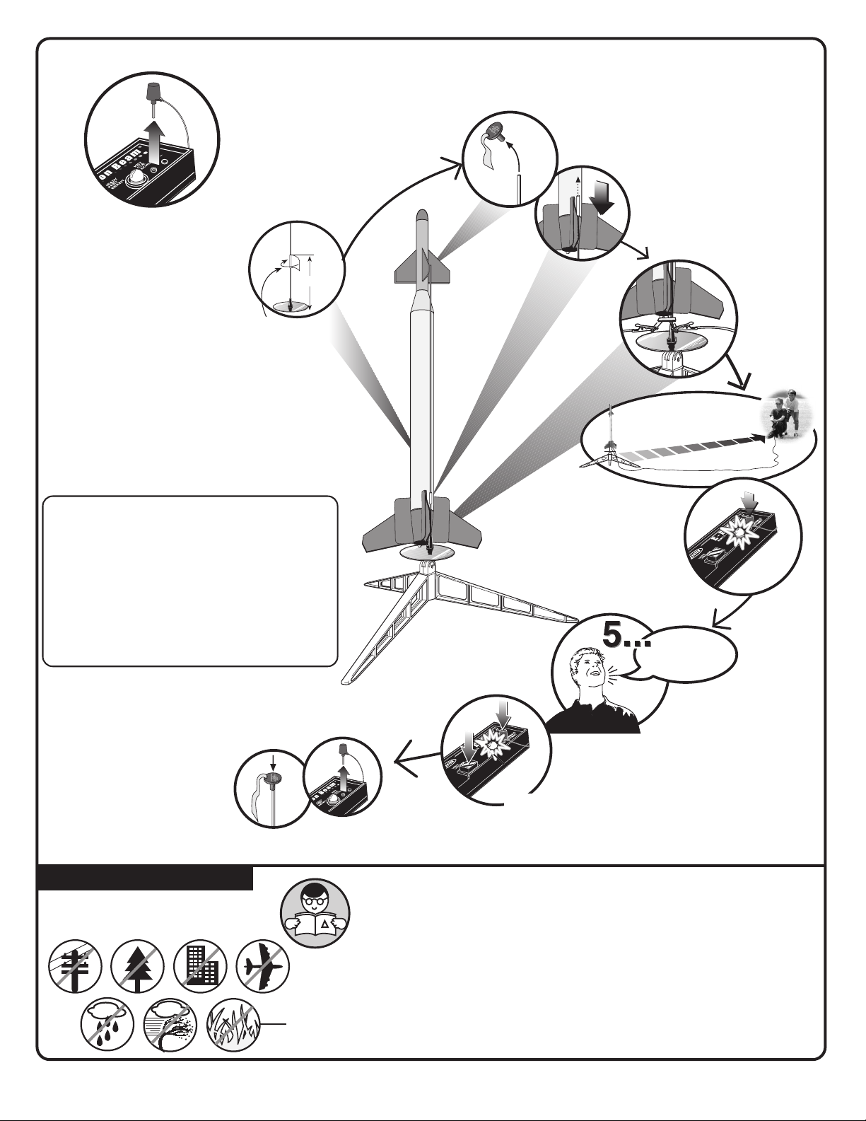
COUNTDOWN AND LAUNCH
4"(10 cm)
KEY ALWAYS OUT UNTIL
FINAL COUNTDOWN!
1...
1...
2...
2...
LAUNCH SUPPLIES
(sold separately):
• Porta-Pad
• Electron Beam
• Recovery Wadding
• Igniters (w/ engines)
• Igniter Plugs (w/ engines)
• Recommended Estes
B4-4, B6-2, B6-4, C6-3, C6-5.
®
II Launch Pad
®
Launch Controller
®
Engines: A8-3, B4-2,
Masking
Tape
3...
3...
15 FT. (5 M)
4...
4...
4... 3... 2... 1...
INSERT KEY.
PUSH DOWN
AND HOLD.
PRECAUTIONS
NAR Safety Code
NO DRY
GRASS
OR WEEDS
HOLD KEY DOWN AND PRESS
LAUNCH BUTTON UNTIL LIFT-OFF!
LAUNCH
BUTTON
FLYING YOUR ROCKET
Choose a large field (500 ft. [152 m] square) free of dry weeds and brown grass. The larger
the launch area, the better your chance of recovering your rocket. Football fields and
playgrounds are great. Launch only with little or no wind and good visibility.
Always follow the National Association of Rocketry (NAR) SAFETY CODE.
MISFIRES
TAKE THE KEY OUT OF THE CONTROLLER. WAIT ONE MINUTE BEFORE GOING
NEAR THE ROCKET! Take the plug and igniter out of the engine. If the igniter has burned,
it worked but did not ignite the engine because it was not touching the propellant inside
the engine. Put a new igniter all the way inside the engine without bending it. Push the
plug in place. Repeat the steps under Countdown and Launch.
© 2003 Estes-Cox Corp. All rights reserved.
PN 60570 (3-02)
 Loading...