

Page 1
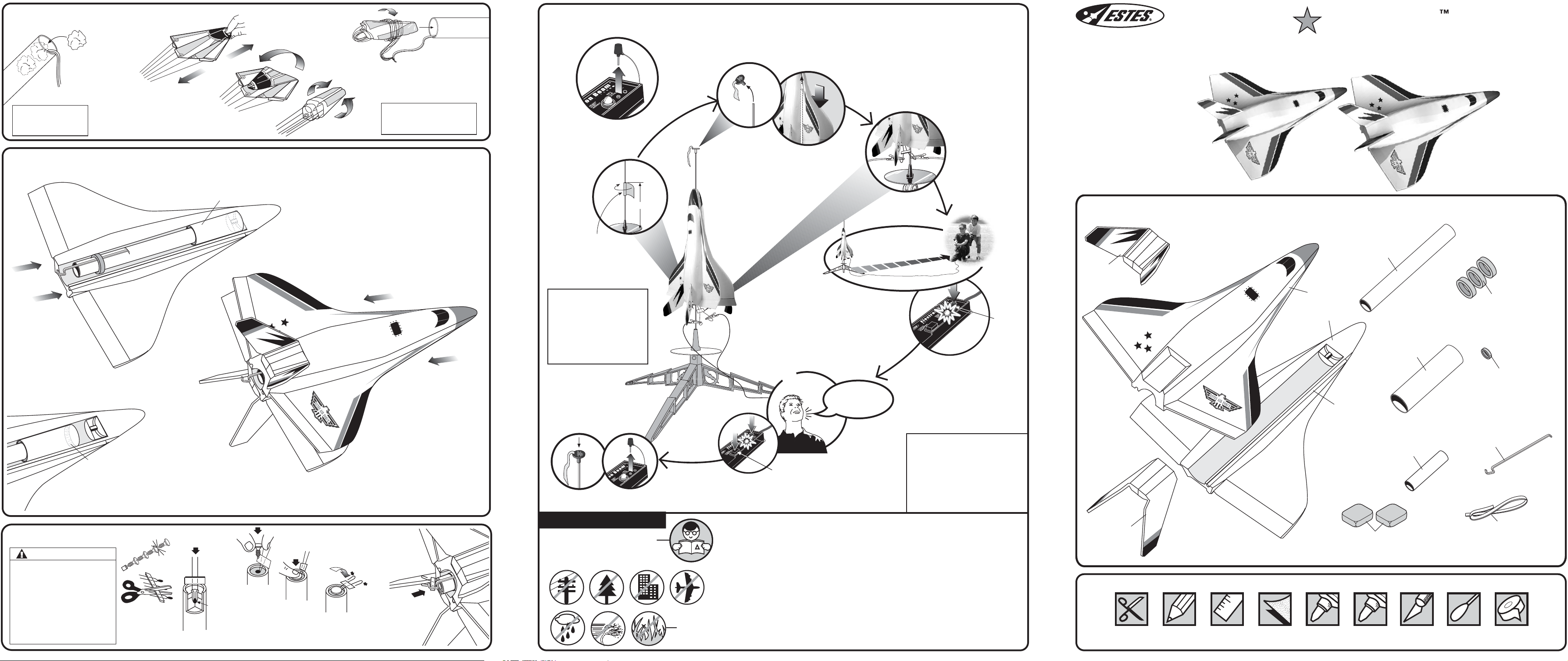
7. PREPARE PARACHUTE FOR FLIGHT
A. Insert 3-4 squares
of loosely
crumpled recovery
wadding into front
of power pod.
IMPORTANT:
Wadding must be in place
and slide freely for rocket
to work properly.
NOTE: Only Estes
Wadding (302274)
Recommended.
B. Spike parachute.
8. PREPARE JETS FOR FLIGHT
A. Prepare parachute
as instructed.
SLIDE POWER POD ALL
C. Fold.
THE WAY FORWARD.
E. Wrap lines loosely. Insert
‘chute, and shock cord into
power pod.
IMPORTANT:
Parachute should slide easily
into body. If fit is too tight, unfold
D. Roll.
B. Slide power pod onto plastic coupler of one
jet, with engine hook in the center.
and repack again.
COUNTDOWN AND LAUNCH
KEY
ALWAYS
OUT UNTIL FINAL
COUNTDOWN!
1...
1...
8" (20.3 cm)
2...
2...
3...
3...
www.estesrockets.com
ESTES INDUSTRIES
1295 H Street
Penrose, CO 81240
PRINTED IN CHINA
AIR SHOW
FLYING MODEL ROCKET KIT INSTRUCTIONS
KEEP FOR FUTURE REFERENCE
ASSEMBLY TIP: Read all
instructions before beginning
work on your model. Make sure
you have all parts and supplies.
TEST FIT ALL PARTS
TOGETHER BEFORE
APPLYING ANY GLUE!
If any parts don't fit properly,
sand as required for precision
assembly.
PARTS Locate the parts shown below and lay them out on the table in front
of you. DO NOT USE THIS DRAWING TO ASSEMBLE YOUR ROCKET.
#1480
MASKING
TAPE
D. Hold gliders vertically. Power pod should remain in
place. If power pod does not stay in place, apply a strip
of masking tape on inside of tube and recheck fit. It
must be snug but not too tight, or jets will not separate.
C. Holding the jet with the power pod firmly in
one hand, slide the second jet onto the front
of the power pod. Make sure both jets are
secured to the power pod.
MASKING
TAPE
NOTE:
So that you don’t loose sight
of your jets or power pod,
it’s a good idea to have
another person observe the
launch and recovery, as the
jets and power pod
descend separately.
15 FT. (5 M)
4...
4...
5...
5...
4... 3... 2... 1...
HOLD KEY DOWN AND
PRESS LAUNCH BUTTON
UNTIL
LIFT-OFF!
KEY
INSERT KEY.
PUSH DOWN
FIRMLY AND
HOLD.
ESTES LAUNCH SUPPLIES
(Sold Separately)
• Recovery Wadding (included with
some engines)
• Igniters (with Engines)
• Igniter Plugs (with Engines)
• Recommended Engines:
B6-2, C6-3
RUDDER
ASSEMBLY (1)
(61011)
ENGINE MOUNT TUBE
BT-760 7.875” (20 cm) (1)
JET FUSELAGE
W/WING (2)
(61010)
LAUNCH LUG 1/8” X 13”
LL-2 (1)
(38187)
(31678)
BODY TUBE
BT-55 4.25” (10.8 cm) (1)
(31679)
YELLOW SPACER
TOOL ET-2 (1)
(35003)
GREEN CENTERING
RING RA-76055 (3)
(30133)
GREEN ENGINE
BLOCK AR-520 (1)
(30162-2)
ENGINE HOOK
EH-2 (1)
(35021)
9. PREPARE ENGINE
WARNING: FLAMMABLE
To avoid serious injury, read
instructions & NAR Safety Code
included with engines.
PREPARE YOUR ENGINE
ONLY WHEN YOU ARE
OUTSIDE AT THE LAUNCH
SITE PREPARING TO
LAUNCH!
If you do not use your prepared
engine, remove the igniter before
storing your engine.
page 5
A. Separate
igniter and
plug.
B. Insert
igniter.
C. Insert
IGNITER MUST
TOUCH
PROPELLANT!
plug.
D. Push
down.
E. Gently bend
igniter wires
to form leads
as shown.
F. Insert engine
into rocket.
PRECAUTIONS
NAR Safety Code
page 6
NO DRY GRASS
OR WEEDS
FLYING YOUR ROCKET
Choose a large field (1000 ft. [305 m] square) free of dry weeds and brown grass.
The larger the launch area, the better your chance of recovering your jets. Football
fields and playgrounds are great. Launch only with little or no wind and good visibility.
Always follow the National Association of Rocketry (NAR) SAFETY CODE.
MISFIRES
TAKE THE KEY OUT OF THE CONTROLLER. WAIT ONE MINUTE BEFORE
GOING NEAR THE ROCKET!
the plug and igniter out of the engine. If the igniter has burned, it worked but did
not ignite the engine because it was not touching the propellant inside the engine.
Put a new igniter all the way inside the engine without bending it. Push the plug in
place. Repeat the steps under Countdown and Launch.
Disconnect the igniter clips and remove engine. Take
© 2005 Estes-Cox Corp. All rights reserved.
PN 61002 (02-05)
RUDDER
ASSEMBLY (1)
(61011)
SUPPLIES In addition to the parts included in the kit you will also need:
SCISSORS PENCIL RULER FINE SAND
PAPER
(#400-600 GRIT)
CARPENTER'S
GLUE
CLAY WEIGHT (2)
(85705)
WHITE
GLUE
HOBBY
KNIFE
COTTON
SWAB
RUBBER SHOCK
CORD 1/8”X18” (1)
(38366)
MASKING
TAPE
Page 2
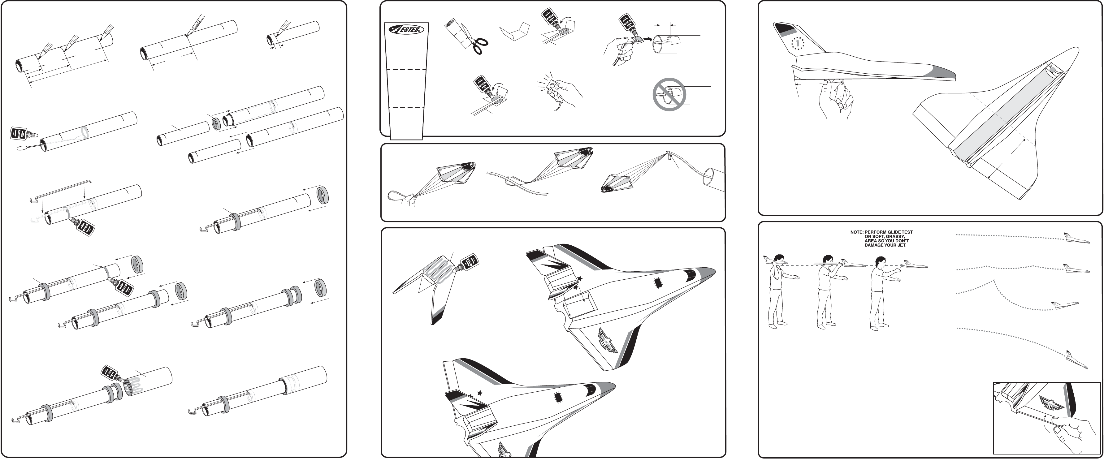
1. ASSEMBLE POWER POD
REAR
1"
(25 mm)
2-3/8"
(6 cm)
A. Measure and mark engine mount tube at
1” (25 mm), 2-3/8” (6 cm) and 7” (17.8 cm).
REAR
D. Use a cotton swab and smear glue 2” (5.1 cm) inside
rear of engine mount tube.
7"
(17.8 cm)
B. Cut a 1/8” (3 mm) slit at the
REAR
3/8"
2-3/8"
(6 cm)
(10 mm)
C. Mark yellow spacer tool
3/8” (10 mm) from end.
2-3/8” (6 cm) mark.
ENGINE
BLOCK
YELLOW
SPACER TOOL
E. Using yellow spacer tool, push engine block into engine mount tube, up
to mark on tool. Remove yellow spacer tool immediately. Let dry.
2. INSTALL SHOCK CORD MOUNT
D
R
O
C
T
K
N
C
U
O
O
H
3
M
S
N
O
I
T
C
E
S
2
N
O
I
T
C
E
SHOCK CORD
MOUNT
SECTION
3
A. Cut out shock cord
S
1
N
O
I
T
C
E
S
B. Fold at
mount at left.
SECTION
SECTION
2
1
3
SHOCK CORD
D. Apply glue. Fold forward.
3. ATTACH PARACHUTE
dotted
lines.
1
2
3
SHOCK
CORD
C. Apply glue.
Fold forward.
E. Squeeze tightly and hold
for one minute.
F. Glue shock cord
mount 1” (25 mm)
inside front of
power pod. Hold
until glue sets. Let
dry.
1”
(25 mm)
YES
DOUBLE
KNOT
NO
5. BALANCE JETS FOR FLIGHT
5"
(12.7 cm)
A. Place a jet on your thumb and finger
approximately 5” (12.7 cm) from the rear of the
jet as shown. See if it will balance.
B. If jet does not balance, add or remove small
amounts of clay weight to the nose cavity until
the jet is balanced or level while holding it as
shown.
5"
(12.7 cm)
CLAY
F. Apply glue around tube just ahead of the 1” (25 mm)
mark. Position and insert engine hook into slit as shown.
7"
(17.8 cm)
GREEN
CENTERING RING
H. Apply glue around tube just ahead of 7” (17.8 cm) mark.
Slide second green centering ring onto engine mount tube
up to the 7” (17.8 cm) mark.
BODY TUBE
GREEN
CENTERING RING
G. Slide one green centering ring (engine hook
retainer) onto engine mount tube and over
engine hook up to the 1” (25 mm) mark.
I. Apply glue around end of tube and slide third
green centering ring onto tube, flush with end.
Let assembly dry.
A. Form loop in
shroud lines.
B. Pass shock cord through loop and tie shock
cord to parachute using a double knot.
4. ATTACH RUDDER ASSEMBLIES
FRONT
SIDES
A. Smear white glue on bottom, sides and
front of one rudder assembly as shown.
B. Attach rudder assembly
to rear of jet. Let dry.
C. Repeat for other jet.
6. GLIDE TEST
A. Hold jet at eye level, aim at a spot about 50 feet
(15 m) away and toss jet straight out.
B. Observe glide carefully. Make adjustments a little
at a time until you are satisfied with the glide.
C. Once satisfied with glide, press clay firmly into
nose cavity.
CORRECT FLIGHT - SLOW
LOSS OF ALTITUDE
LIGHT STALL - OK
HEAVY STALL - NO GOOD
STEEP DIVE - NO GOOD
REPAIRING THE JETS
Use white glue to repair any breaks
in the foam on the jets. Make sure to
let the glue dry completely before
attempting to launch. After the repair,
you should check the balance of the
J. Smear glue up to 1/2” (13 mm) inside end of body tube.
Insert engine mount sub-assembly into tube until second
K. Completed power pod. Let dry.
C. Repeat for other
jet. Let dry.
green centering ring is flush with end of tube.
page 2 page 3 page 4
jet and perform a glide test before
launching. See Step 5 for balancing
and Step 6 for the glide test.
GLIDER ADJUSTMENTS:
If jet DIVES: Remove weight, a little at a time, from
nose cavity.
If jet STALLS: Add clay weight, a little at a time, to
nose cavity.
If jet TURNS TOO SHARPLY: Gently bend elevator
section of the down wing up.
The jet should perform a large, gliding circle during
descent.
 Loading...