

Page 1

COUNTDOWN AND LAUNCH
8 (20.4 cm)
ESTES LAUNCH SUPPLIES
To launch your rocket, you will need the following:
¥ Porta-Pad¤ II Launch Pad
¥ Electron Beam
¥ Recommended Engines: B4-2, B6-2, C6-3
¥ Igniters and Igniter Plugs (included with Estes engines)
¤
Launch Controller
SCISSOR WING TRANSPORT
www.estesrockets.com
ESTES INDUSTRIES
1295 H Street
Penrose, CO 81240
PRINTED IN CHINA
ASSEMBLY TIP: Read all instructions
before beginning work on your model.
Make sure you have all parts and supplies.
FLYING MODEL ROCKET
KIT INSTRUCTIONS
KEEP FOR FUTURE REFERENCE
#1265
KEY ALWAYS OUT UNTIL
FINAL COUNTDOWN!
MASKING
TAPE
1...
1...
NOTE: So that you don’t lose
sight of your Glider or
Power Pod, it’s a good idea
to have another person
observe the launch, as the
Glider and Power Pod
descend separately.
2...
2...
3...
3...
15 FT. (5 M)
4...
4...
4... 3... 2... 1...
HOLD KEY DOWN AND PRESS
LAUNCH BUTTON UNTIL
LIFT-OFF!
KEY
INSERT KEY.
PUSH DOWN
AND HOLD.
TEST FIT ALL PARTS TOGETHER
BEFORE APPLYING ANY GLUE!
If any parts don’t fit properly, sand as
required for precision assembly.
PARTS Locate the parts shown below and lay them out on the
table in front of you. DO NOT USE THIS DRAWING TO ASSEMBLE
YOUR ROCKET.
BODY TUBE BT-50 18" (1)
(30352)
POWER POD BT-20 12" (1)
RUDDER TUBE BT-50J 2-3/4" (1)
YELLOW SPACER
TOOL ET-2 (1)
(35003)
(30451)
(30362)
MYLAR RETAINER
RING (1)
NOSE CONE INSERT
PIN-50 YR (1)
(72605)
GREEN ENGINE
BLOCK AR520 (1)
(30168)
PLASTIC NOSE CONE
PNC-50YR (1) (72604)
GREEN CENTERING
RINGS AR2050 (2)
(30162-2)
ELASTIC THREAD ET-1
(85772)
(30164-2)
ENGINE HOOK
EH-2A (1)
(35021)
RUBBER BAND #8 (2)
44060
CLAY WEIGHT (1)
(85704)
WING
PIVOT
LAUNCH LUG
LL2B (1)
(38178)
WOOD DOWEL 1/8" X 9"
ASSEMBLED 12" (30 cm)
PARACHUTE (1)
(35801)
WING
PIVOT CAP
WING
HOLDER
PIVOT BASE
PLASTIC PARTS SET (60832)
(32054)
PRECAUTIONS
NAR Safety Code
12.
NO DRY GRASS
OR WEEDS
LAUNCH BUTTON
FLYING YOUR ROCKET
Choose a large field (500 ft. [152 m] square) free of dry weeds and brown grass. The
larger the launch area, the better the chance of recovering your rocket. Football fields
and playgrounds are great. Launch only with little or no wind and good visibility.
Always follow the National Association of Rocketry (NAR) Safety Code.
MISFIRES
TAKE THE KEY OUT OF THE CONTROLLER. WAIT ONE MINUTE BEFORE GOING
NEAR THE ROCKET! Disconnect the igniter clips and remove the engine. Take the
plug and igniter out of the engine. If the igniter has burned, it worked but did not ignite
the engine because it was not touching the propellant inside the engine. Put a new
igniter all the way inside the engine without bending it. Push the plug in place. Repeat
the steps under Countdown and Launch.
' 2004-2005 Estes-Cox Corp. All rights reserved.
P/N 83130 (1-05)
DECAL SHEET WITH TAPE HINGES (37065)
SUPPLIES In addition to the parts included in the kit you will also need:
SCISSORS PENCIL RULER FINE SAND
PAPER
(#400-600 GRIT)
CARPENTER’S
GLUE
HOBBY
KNIFE
PLASTIC
MODELING
CEMENT
LASER CUT BALSA SHEET 1/8" (3 mm) 32229
LASER CUT BALSA SHEET 1/16" (2 mm) (32228)
MASKING
TAPE
RAZOR
SAW
TWEEZERS SPRAY
PRIMER
WHITE
SPRAY
PAINT:
BLACK
WHITE
Page 2

REFERENCE SHEET & MARKING GUIDES
CUT OUT FOR STEP 1-A CUT OUT FOR STEP 7-A
HOOKENGINE
FIN
TUBE MOUNT SPACER
DOWEL MOUNT CENTER
WING
FIN
POWER POD
MOUNTDOWEL
RUDDER
TUBE MARKING GUIDE
POD FIN BRACES
ELEVATOR
STABILIZER
MOUNT
TUBE
RUDDER MOUNT
TUBE MARKING GUIDE
PLASTIC WING
HOLDER A & B
PLASTIC WING
PIVOT CARD
GLIDE TEST
NOTE: Test the Glider only on soft, grassy surfaces like a sports field or lawn
so that you don t damage your model.
A. With Power Pod removed from Glider, aim at a spot about 50
feet away and toss Glider straight out at eye level.
B. Observe glide carefully. Make adjustments a little at a time
until you are satisfied with the glide.
GLIDER ADJUSTMENTS:
If Glider dives:
1) Remove weight from nose cone, or
2) Add weight inside of rudder tube, or
3) Lightly sand angled part of Tube Mount to increase elevator movement
If Glider stalls:
1) Add weight to nose cone, or
2) Remove weight from rudder tube, or
3) Add shims to angled part of Tube Mount to decrease elevator movement
If Glider turns too sharply:
1) Be sure that wing is at right angles to body tube in glide position.
2) Make sure that wing snaps firmly into glide position when released.
3) Make sure model balances span wise (from side to side). If not, add
weight, in small amounts, to the light wing tip until nearly balanced.
The Glider should perform a large, gliding circle during descent.
CORRECT FLIGHT-SLOW
LOSS OF ALTITUDE
LIGHT STALL-OK
HEAVY STALL-
CORRECT IT
DON’T LET THIS DIVE
HAPPEN TO YOU!
1/8" LASER CUT BALSA SHEET
BALSA SHEETS
NOT TO SCALE
1/16" LASER CUT BALSA SHEET
TUBE MOUNT
RUDDER
DOWEL MOUNT BRACES
POD FINS
DOWEL MOUNT SIDES
PLASTIC WING
PIVOT
PLASTIC
PIVOT BASE
PLASTIC PARTS
NOT TO SCALE
ROCKET PREFLIGHT
Wrap parachute around Power Pod as shown and slide into Main Body Tube
using a twisting motion. Turn wing to ’booster’ position. Make sure dowel
on Power Pod goes through the Launch Lugs on the Tube Mount and wing
tip. Also make sure that the Dowel Mount is over the elevator, holding it in
the horizontal position. For your first flight, use a B6-2 engine. Tape Nose
Cone securely as shown for your first flight.
PREPARE ENGINE
WARNING: FLAMMABLE
To avoid serious injury, read
instructions & NAR Safety Code
included with your engines.
PREPARE YOUR ENGINE
ONLY WHEN YOU ARE
OUTSIDE AT THE LAUNCH
SITE PREPARING TO
LAUNCH!
If you do not use your prepared
engine, remove the igniter before
storing your engine.
A.
IGNITER MUST
TOUCH
PROPELLANT!
B.
SCISSOR WING TRANSPORT & BOOSTER
POD IN "BOOST" CONFIGURATION
DOWEL HOLDING WING IN
"BOOST" CONFIGURATION
NOTE: After you have flown and are sure your glider
is balanced correctly, you can glue the nose cone
on permanently using plastic cement.
C.
D.
E.
TAPE NOSE CONE SECURELY
FOR YOUR FIRST FLIGHT
F.
INSERT ENGINE
INTO ROCKET.
2. 11.
Page 3
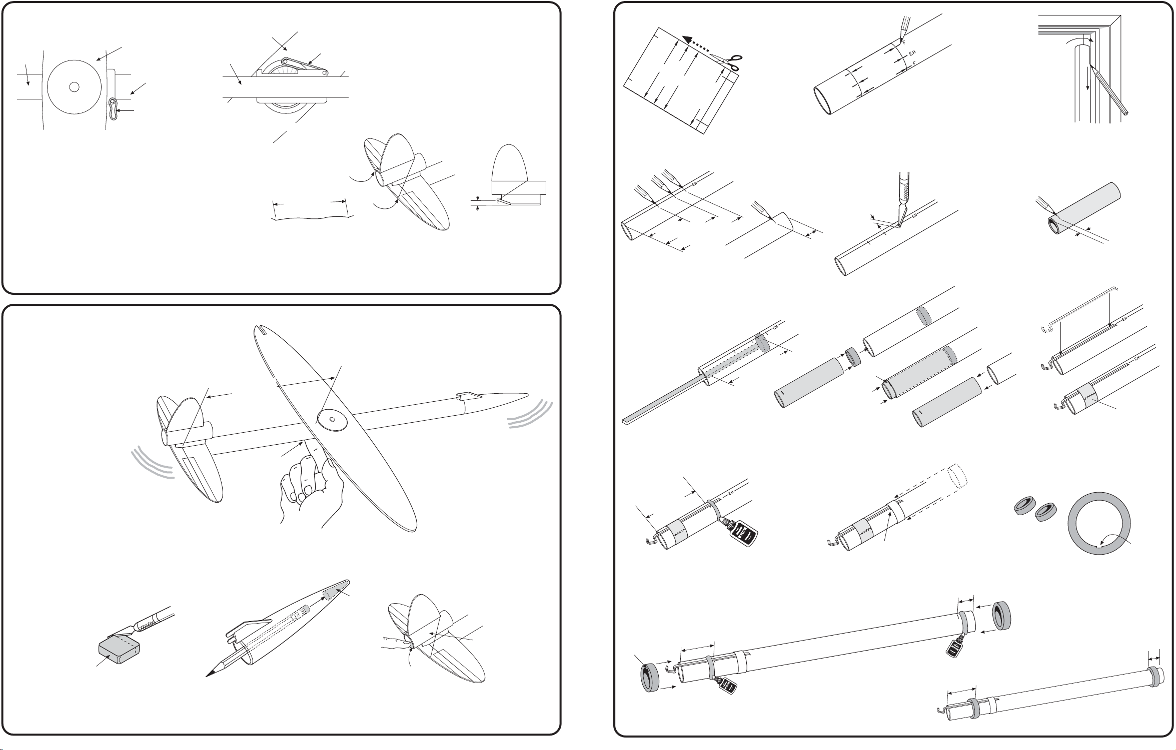
INSTALL RUBBER BAND & ELASTIC THREAD
WING AT 45ß
BODY
TUBE
TOP VIEW
A. Hook one end of Rubber Band over Pivot Base Pin.
Move wing to about 45ß, turn rocket over, and hook the
other end over pin on wing pivot.
B. Remove any twists from rubber band. Check to
make sure wing pivots into "glide" position when
released. If wing binds, try a little silicon spray
lubricant on plastic pivot parts .
WING AT 90ß
BODY TUBE
PIVOT BASE PIN
RUBBER BAND
BOTTOM VIEW
3-1/2" (8.9 cm)
C. Tie two knots in elastic thread 3-1/2"
thread through notches in elevator and rudder as shown. Be
sure elevator moves up against tube mount sides and that
rear of elevator is at least 1/8" (3 mm) above horizontal when
raised. If necessary, sand lower portion of tube mount sides
to allow more elevator movement.
RUBBER BAND
KNOT
KNOT
1/8"
(3 mm)
SIDE VIEW
(8.9 cm) apart. Stretch
1. ASSEMBLE POWER POD
FIN
W
O
P
BE M
TU
(5.1 cm)
2"
D
G
G
ER PO
RKIN
A
2-1/2"
E
ID
U
MOUNTDOWEL
(6.4 cm
NT
O
FR
)
(13 m
1/2"
FIN
HOOKENGINE
A. Cut out power pod marking
guide from page 2.
1-7/16"
(3.7 cm)
EAR
R
D. Mark tube on the "EH" line at 1-7/16"
(3.7 cm), 2" (5.1 cm) and 2-1/2" (6.4 cm).
Mark tube 1/2" (13 mm) from front end.
FIN
K
O
O
H
E
IN
G
N
E
FIN
B. Wrap power pod marking guide
around BT-20 Power Pod Tube,
secure with tape. Mark at each
arrow point and identify.
1/8"
(3 mm)
m
FR
T
ON
)
E. Cut 1/8" (3 mm) slit at
2-1/2" (6.4 cm) mark.
DOOR
FRAME
C. Remove marking guide. Using
door frame, extend all lines
entire length of tube.
)
m
(6 m
1/4"
F. Mark yellow spacer tool at 1/4"
(6 mm) from end.
BALANCE GLIDER
A. With Wing in glide position (at right angles to body
tube), check the center of gravity location. It should be
between 8-3/4
of the body tube.
(22.2 cm) and 9 (22.9 cm) from the rear
8-3/4 - 9"
(22.2-22.9 cm)
CENTER OF
GRAVITY
CENTER OF GRAVITY IS THE
POINT WHERE PLANE IS
CLAY
W
EIGHT
LEVEL W
HEN BALANCED ON
YOUR FINGER
REAR
2-1/4"
G. Use scrap balsa to smear
glue 2-1/4" (5.7 cm) inside
end of power pod tube.
)
(5.1 cm
2"
J. Apply a line of glue around
tube just in front of 2"
(5.1 cm).
(5.7 cm
)
(6 mm)
K
AR
M
1/4"
H. Push engine block into power pod tube with
spacer tool up to mark. Remove spacer tube
immediately. Let dry.
2" (5.1 cm) MARK
K. Slide mylar retainer ring over front
of tube, push up to the 2"
mark. Carefully remove tape. Let
1/2" (13 mm)
(5.1 cm)
MASKING
TAPE
I. Position engine hook.
Temporarily tape into place.
NOTCH
L. Locate the two green centering rings.
Notch one of the rings 1/32" (1 mm)
deep and 1/8" (3 mm) wide with a
hobby knife.
1-7/16"
(3.7 cm)
M. Apply glue band just behind 1-7/16"
1-7/16"
(3.7 cm)
1/2" (13 mm)
CLAY
W
EIGHT
NOSE CONE
CLAY
W
EIGHT
RUDDER
TUBE
NOTCH
(3.7 cm) mark and slide notched ring
B. If the glider does not balance between these two points, add clay weight, in small amounts,
to the nose cone or rear rudder tube. Make adjustments a little at a time until you are
satisfied that the glider is balanced.
up to mark. Repeat for other end-slide
ring to 1/2" (13 mm) mark.
COMPLETED POWER POD
ASSEMBLY
10. 3.
Page 4
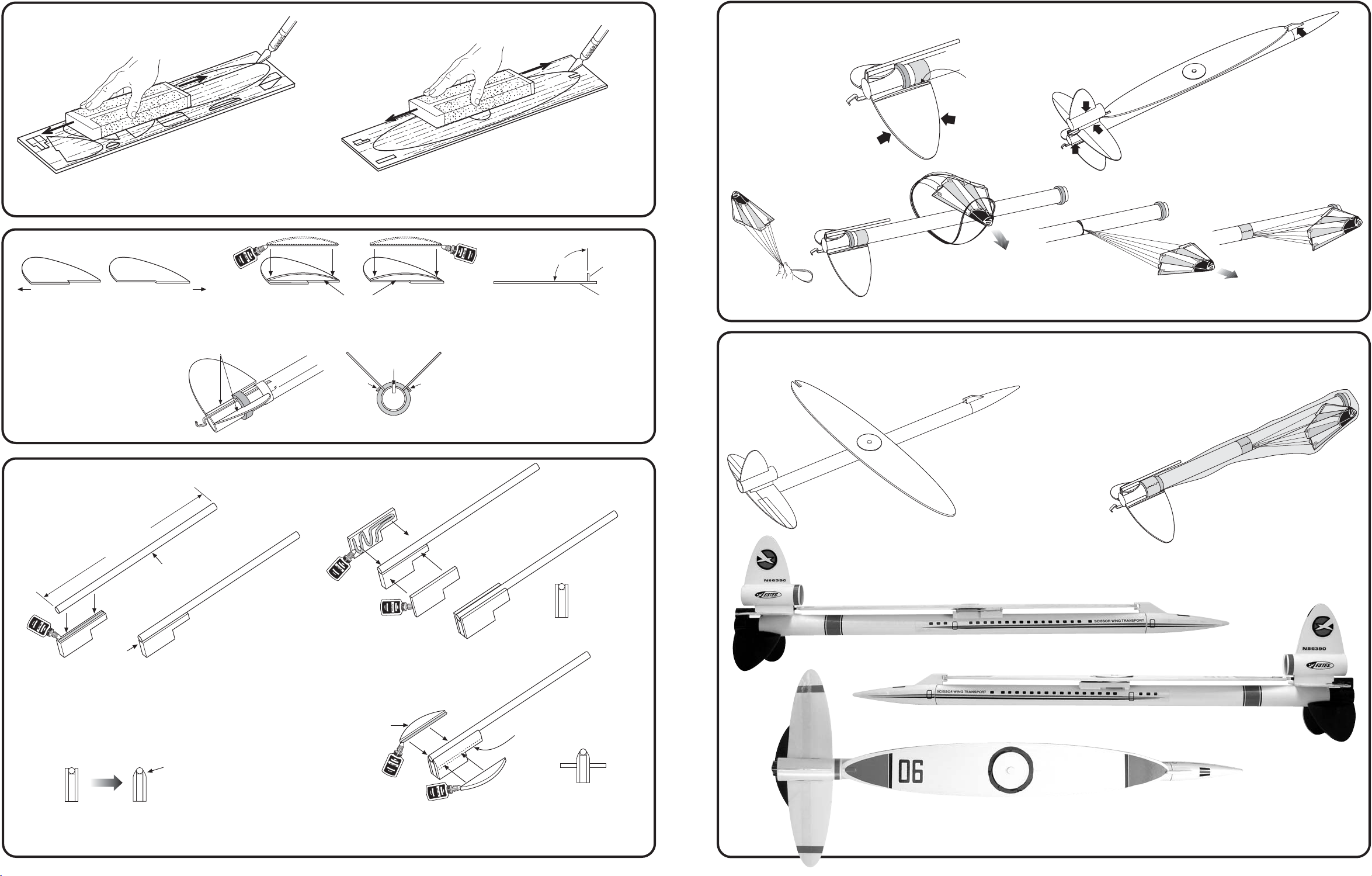
2. PREPARE BALSA PARTS
1/8" (3 mm) LASER CUT BALSA SHEET
A. Sand both sides of each balsa sheet with fine sand paper. Carefully remove pieces. Lightly sand
edges smooth, but
do not round
3. ATTACH FINS
FIN TABFIN TAB
A. Lay out the two Pod Fins with fin
tabs facing away from each other.
edges.
FLUSH
B. Glue Pod Fin Braces onto Pod Fins
at 90ß angle as shown.
1/16" (2 mm) LASER CUT BALSA SHEET
90ß
BRACE AT RIGHT
ANGLES TO FINS.
BRACE
POD FIN
PREP ROCKET FOR FINISHING
A. Sand edges of
Power Pod fins to a
rounded shape. Do
not round portion of
fins between fin
braces and Power
Pod Tube.
FORM
LOOP
ROUND
EDGE
C. Attach parachute to Power Pod. Loop shroud lines around center of Power
Pod, pull tightly. Wrap a band of masking tape to secure to tube.
ROUND
EDGE
DO NOT
SAND
B. Check model and do
your final sanding and
reinforcing of glue joints
in preparation for
finishing.
GLUE FILLETS
GLUE FILLETS
FIN TABS
C. With Fin Braces to the
outside and fin tabs to the
rear, glue Pod Fins to Power
Pod Assembly as shown.
Let dry completely.
4. ASSEMBLE DOWEL MOUNT
(8.9 cm)
3-1/2"
1/8"
(3 mm)
WOOD DOWEL
FLUSH &
CENTERED
A. Cut a 3-1/2"
the 1/8"
to the Dowel Mount Center piece
(from the 1/8"
C. Sand to cross section as shown.
(8.9 cm) long piece from
(3 mm)
wood dowel. Glue it
(3 mm)
sheet). Let dry.
END VIEW
SAND TOP TO
THIS SHAPE
ENGINE
HOOK
REAR VIEW
B. Glue Dowel Mount Side
pieces to assembly as
shown. Let dry.
DOWEL MOUNT BRACE
D. Glue Dowel Mount Braces to Dowel Mount Sides.
Do not glue Dowel Mount to Power Pod yet. This
will be done later to assure proper alignment.
PAINT SCHEME
For optimum performance, keep weight to a minimum. We recommend light coats of primer and paint.
BRACEBRACE
NOTE: Fins must be
attached correctly
for stable flight.
END VIEW
EVEN
WITH
EDGE
END VIEW
A. Remove Power Pod and spray rocket with
white primer. Mask Power Pod as shown
and do the same. Let dry and sand.
Repeat until smooth.
B. Paint entire rocket gloss
white. Paint the primed
area of Power Pod gloss
black. Let dry.
NOTE: Be careful when painting to avoid "FREEZING" the wing
pivot. Wing must pivot FREELY for proper operation.
RIGHT SIDE
LEFT SIDE
GLUE AT 90ß
TOP
C. When paint is dry, peel decals one at a time from decal sheet
and apply where shown. Rub down to remove bubbles.
4. 9.
Page 5
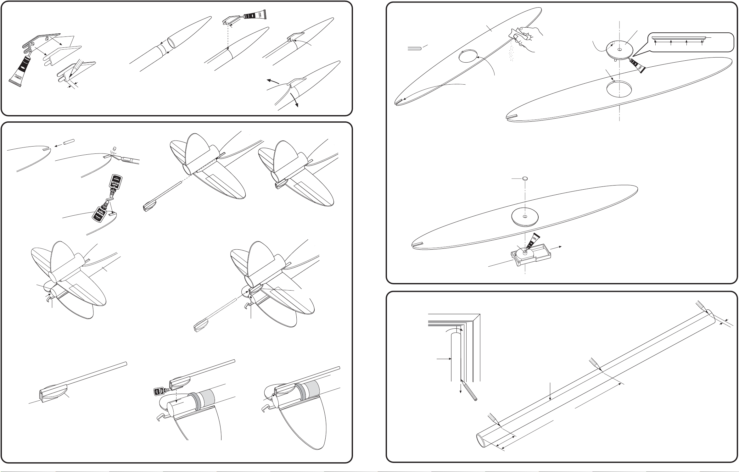
9. ASSEMBLE NOSE CONE
PLASTIC WING
HOLDER
NOTE: DO NOT
GLUE NOSE
CONE TO NOSE
CONE INSERT!
DON’T
GLUE PAST
MARK
1/8" (3 mm)
MARK EVEN
WITH JOINT
5. ASSEMBLE WING
A. Lightly sand outside edges
of wing and round slightly.
ROUND
EDGE
WING
LOCATING TAB
ON BOTTOM
SIDE
PLASTIC WING
PIVOT
[FLAT SIDE UP]
FLANGE
CEMENT
)
m
1/8"
(3 m
B. Slide Nose Cone onto Nose Cone Insert. Apply
plastic cement to base of Wing Holder up to
mark as shown. Glue Wing Holder to Nose Cone,
A. Apply plastic cement to one half of Wing
Holder, press both halves together. Mark
at 1/8" (3 mm) as shown. Let dry.
center on body tube reference line. Make sure
that wing tip will swing freely between posts on
Wing Holder. Let dry.
10. ATTACH DOWEL MOUNT
A. Place remaining
piece of Launch
Lug into slot at
end of wing. Trim
to fit. Glue in place
and let dry.
BODY
POWER
POD
ENGINE
HOOK
C. Slip Power Pod all the way into rear of main Body Tube until
the Rear Centering Ring is flush with the end of the Body
Tube. If necessary, sand centering rings for a loose sliding
fit in Body Tube. There should be no binding. The Engine
Hook should be centered on the bottom of the Body Tube.
TUBE
WING TIP
SHOULD
SWING FREELY
B. Position Wing in "boost" position (with its wing parallel to Body Tube)
and insert Dowel Mount (from step 4) through Launch Lug in Rudder
Tube Mount into Launch Lug in wing slot. The Dowel Mount Braces
should hold the elevator in a nearly horizontal position. Then remove it.
DOWEL MOUNT
BRACE
FLUSH WITH
END OF TUBE
D. Test fit Dowel Mount to Power Pod. Dowel should extend
through Launch Lug in Rudder Tube Mount. The rear of the
Dowel Mount should be flush with rear of Power Pod Tube.
NOTCH
DO NOT ROUND
EDGES OF CENTER
HOLE OR SLOT.
WING TOP
REAR
B. Position wing as shown. Apply plastic cement to underside of flange
on Plastic Wing Pivot. Wing locating tab must be lined up with
notch in wing, insert Wing Pivot. Pivot must be flush to top of wing.
Let plastic cement dry completely.
WING PIVOT CAP
C. Position Plastic Pivot Base as shown.
Line up tab on base with mounting hole
on wing pivot. Press together, check
movement, must be free. Apply a drop
of plastic cement into center of mounting
hole in tab, insert wing pivot cap. Must
be flush. Let dry completely.
PLASTIC PIVOT BASE
TAB
LONG END
TOWARD FRONT
OF WING
6. ASSEMBLE STABILIZER AND ATTACH WING TO BODY TUBE
DOOR
FRAME
BT-50 BODY
TUBE
NOTE: WING MUST BE
POSITIONED EXACTLY AS
SHOWN FOR PROPER
INSTALLATION OF
PLASTIC PIVOT PARTS!
1/8"
(3 m
FRONT
FRONT
)
m
ALIGNMENT LINE
BOTTOM
DOWEL MOUNT
BRACE
E. It will be necessary to sand forward portion
of Dowel Mount Braces in order to clear
FLUSH
A. Using a door frame
as a guide, draw a
line full length of the
body tube.
B. Mark body tube 1-1/2" (3.8 cm) and
9" (22.9 cm) from end. Mark tube
1/8" (3 mm) from front.
9" (22.9 cm)
Tube Mount sides properly. Round bottom
surface of Dowel Mount Assembly to fit
tube.When you are sure that you have all
parts fitted properly, mark location of Dowel
Mount on Power Pod Tube.
F. Remove Power Pod and glue dowel
mount into position flush with end
of tube. Let dry.
REAR
COMPLETED ASSEMBLY
1-1/2" (3.8 mm)
8. 5.
Page 6
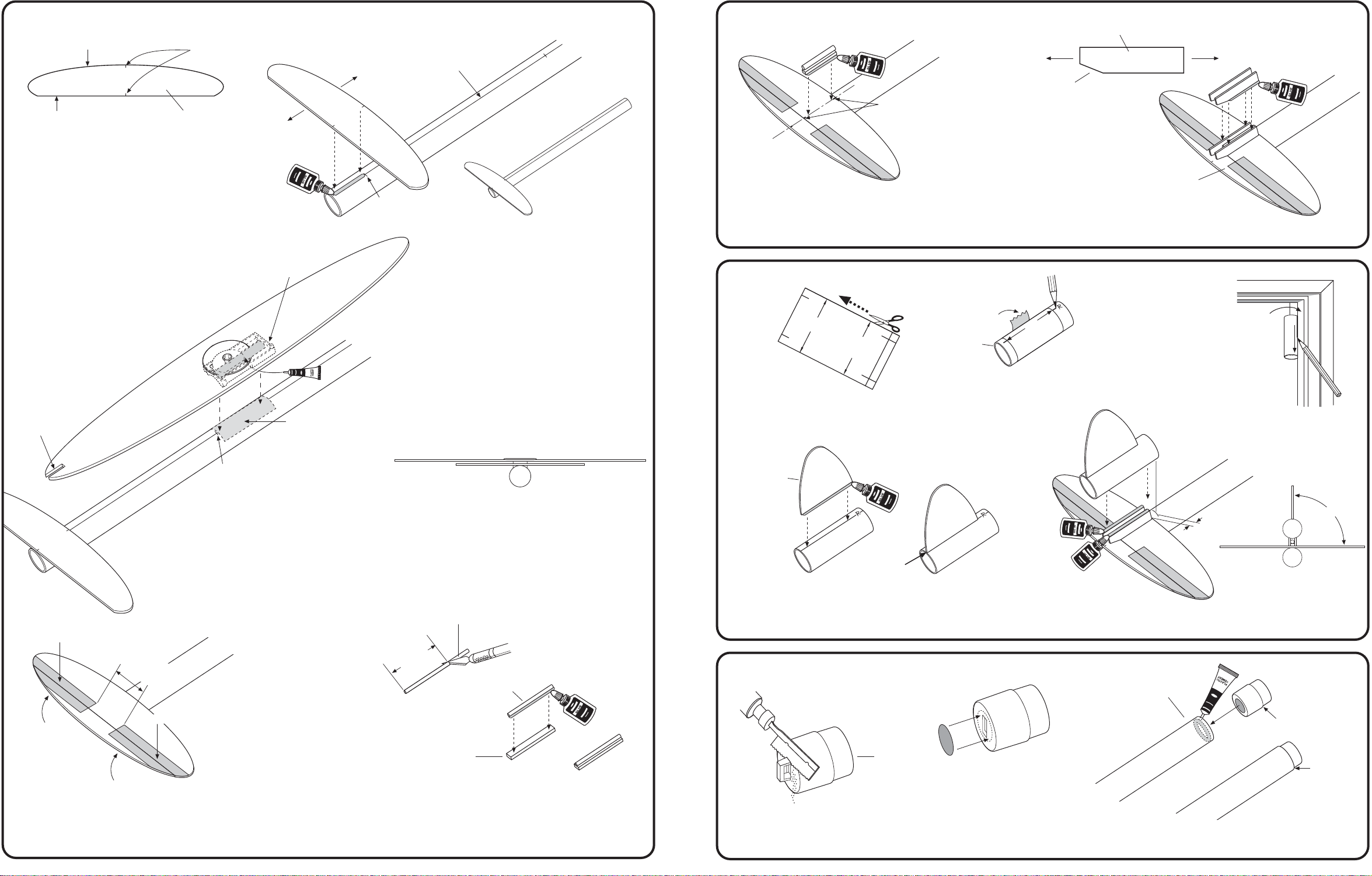
6. ASSEMBLE STABILIZER (Continued.)
CURVED
STRAIGHT
C. Apply a line of glue onto the
alignment line up to the 1-1/2"
(3.8 cm) mark. Align marks on
Stabilizer with line on Body
Tube and position Stabilizer
even with end of body tube.
Let dry.
ALIGNMENT MARKS
STABILIZER
STRAIGHT
CURVED
(3.8 cm)
MARK
11/2"
ALIGNMENT LINE
COMPLETED
ASSEMBLY
6. ASSEMBLE STABILIZER (Continued)
ALIGNMENT
MARKS
G. Glue tube mount spacer to main portion of stabilizer.
Center on alignment marks as shown.
TUBE MOUNT
FRONTREAR
SLANT
NOTE: Do not put glue
on slant edge
or on elevator.
ELEVATOR
H. Glue a Tube Mount to each side of Tube Mount
Spacer. Position as shown. Elevator must be
free to raise slightly. Let dry.
NOTCHED END
TO REAR
TAPE HINGE
PIVOT BASE
USE SANDPAPER TO
ROUGHEN TUBE
SURFACE AREA WHERE
PIVOT BASE MOUNTS
FOR A BETTER
9" (22.9 cm)
CEMENT BOND.
D. Apply band of cement to under side of
Plastic Pivot Base as shown. Glue Wing
Assembly to body tube centered on
reference line with rear of Pivot Base
at the 9" (22.9 cm) mark.
ROTATE WING 90ß, MAKE SURE WING
IS PARALLEL TO STABILIZER. ALLOW
CEMENT TO DRY COMPLETELY.
REAR VIEW
LAUNCH LUG
7. ATTACH RUDDER
E
T
ID
DER
N
U
U
RUD
G
O
G
M
IN
R
K
NT
E
R
D
A
D
MOU
U
M
E
E
R
B
TUB
U
T
A. Cut out Rudder
Mount Tube Marking
Guide from page 2.
RUDDER
REAR
D. Apply glue to Rudder and attach to Rudder
tube. Center on rudder line flush with rear
of tube. Let dry.
FLUSH
TAPE
DER
RUDDER
TUBE
RUD
RUDDER MOUNT
TUBE MARKING GUIDE
B. Wrap guide around Rudder Tube,
secure with tape. Mark tube at
arrow points put an "R" at rudder
line and "TM" at tube mount line.
DOOR
FRAME
C. Remove marking
guide. Extend all
lines entire length
of tube.
5/16" (8 mm)
REAR VIEW
E. Glue Rudder Assembly to Tube Mount. Front of
tube should be 5/16" (8 mm) forward of front of
Tube Mount. Center at 90ß angle to Stabilizer.
90ß
1-3/8"
1" (2.5 cm)
SPACE
TAPE HINGE
E. Attach Elevator to Stabilizer using self-adhesive Tape
Hinges from decal sheet. Fold Elevator up and back
several times to crease hinges and to insure proper
operation.
(3.5 cm)
LAUNCH LUG
TUBE MOUNT
SPACER FROM
1/8" (3 mm)
SHEET
COMPLETED
ASSEMBLY
F. Cut a a piece of the Launch Lug to 1-3/8"
long. Glue launch lug to wide side of Tube Mount
Spacer. Let dry.
(3.5 cm)
8. INSTALL NOSE CONE INSERT
NOSE
CONE
INSERT
A. Using a razor saw, carefully cut
off eyelet flush with end. Sand
as required for a flat surface area.
B. Locate and remove red
Engine Debris Block
from decal sheet. Center
over end of insert and
press into place.
FRONT OF BODY
TUBE/WING ASSEMBLY
SHOULDER
SHOULDER
FLUSH
WITH END
C. Apply plastic cement inside front of Body Tube. Push
insert in until shoulder is flush with tube end. Let dry.
6. 7.
 Loading...