

ESTERS ELEKTRONIK FMP 1836 Instruction Manual

P
=
Speed Pressure Flow Rate Temperature
Instruction Manual IM 109
-
8008
E
Page
1
Phone:
+49 (0)
6021 –
45 807
-0
Esters Elektronik GmbH
eMail:
info@esters.de
INSTRUCTION MANUAL IM 109-8008 E
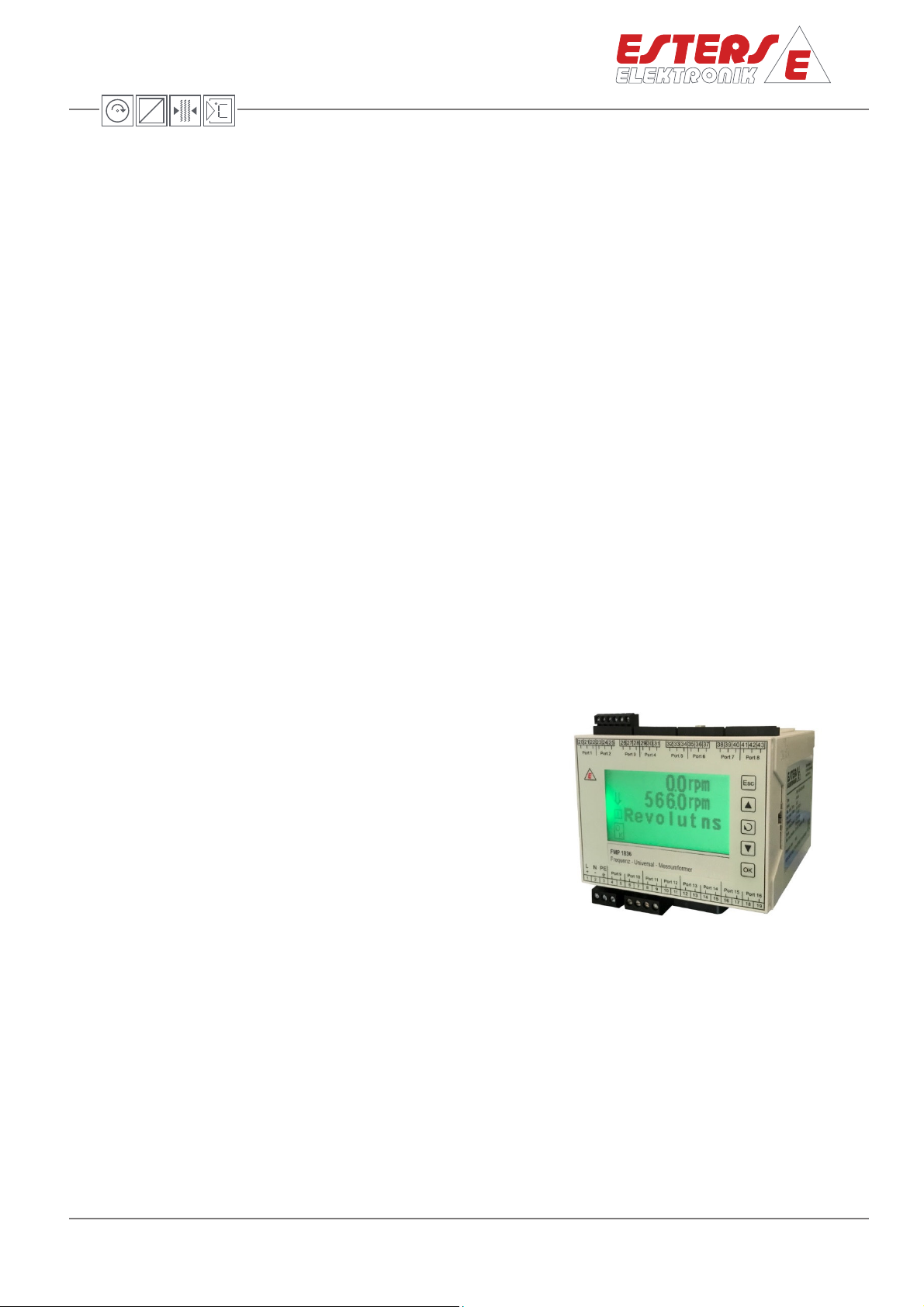
Device: FMP 1836 - with LCD display
Frequency Transducer for limit value monitoring or
recognition of the direction of speed
Content: Instruction manual
Rev.-No.: IM 109 E V1.0-2019-01-25
Rev.-Nr.: IM 109 E V1.0-2019-01-25
Fax: +49 (0) 6021 – 45 807 -0
Hafenrandstr. 14 · D-63741 Aschaffenburg
Internet: http://www.esters.de

P
=
Speed Pressure Flow Rate Temperature
Instruction Manual IM 109
-
8008
E
Page
2
Phone:
+49 (0)
6021 –
45 807
-0
Esters Elektronik GmbH
eMail:
info@esters.de
Esters Elektronik GmbH
Hafenrandstr. 14
D-63741
Aschaffenburg
Tel.: +49 (0)
6021
– 45 807
-0
Fax: +49
(0) 6021
– 45 807
-0
eMail: esters@esters.de
Internet: www.esters.de
© Esters Elektronik GmbH,
Aschaffenburg
User information
- Prior to installing the equipment or before attempting initial start-up, please read this manual
thoroughly.
- Please ensure to observe all information and warnings provided in this manual.
- The serial number of the equipment can be found on the identification plate. You will need this
information when ordering spare parts. The plate is attached to the outside of the device.
- Installation, start-up and maintenance may only be performed by an electrician. The local guidelines
of the place of installation have to be observed.
- Maintenance may only be performed under dead-voltage conditions for personal security reasons.
- In order of guarantee operational safety, only the manufacturer's original spare parts shall be
installed.
- Operating the equipment for purposes other than its intended use shall void all warranty claims and
product liability. Noncompliance with the intended use refers to but is not limited to improper
installation, start-up, operation, maintenance and neglecting the information provided in this
manual.
- The device must be integrated into the lightening protection concept of the plant.
Please ensure to operate this device only in accordance with this manual.
Departure from these instructions will void and nullify all warranty claims and
jeopardizes the operating safety of the device.
Rev.-Nr.: IM 109 E V1.0-2019-01-25
We reserve the right to engineering changes, which may necessitate deviations from the current data
provided in this manual. Should you require additional information or questions arise that are not
sufficiently covered in this manual, please contact us at the following address:
Imprint
Copyright
This manual is protected by copyright.
Duplication or distribution is not permitted without express written approval.
Fax: +49 (0) 6021 – 45 807 -0
Hafenrandstr. 14 · D-63741 Aschaffenburg
Internet: http://www.esters.de

P
=
Speed Pressure Flow Rate Temperature
Instruction Manual IM 109
-
8008
E
Page
3
Phone:
+49 (0)
6021 –
45 807
-0
Esters Elektronik GmbH
eMail:
info@esters.de
Table of content
1 Introduction ___________________________________________________________________ 4
1.1 Operating instructions, general information ________________________________________ 4
1.2 Goods receipt inspection, transportation, storage ___________________________________ 4
2 Warranty ______________________________________________________________________ 4
3 General information _____________________________________________________________ 5
4 Installation / servicing / maintenance______________
_________________________________ 6
5 Technical specifications __________________________________________________________ 6
5.1 Input _______________________________________________________________________ 6
5.2 Output ______________________________________________________________________ 6
5.3 Relay _______________________________________________________________________ 7
5.4 Types of limit values ___________________________________________________________ 7
5.5 Electrical values ______________________________________________________________ 7
5.6 Environmental influences _______________________________________________________ 7
5.7 Mechanical values ____________________________________________________________ 8
5.8 Display and housing ___________________________________________________________ 8
5.9 Interface ____________________________________________________________________ 8
5.10 Software ____________________________________________________________________ 8
5.11 Interfaces and connecting diagram _______________________________________________ 8
5.11.1 Power supply ________________________________________________________________ 8
5.12 Connecting diagram ___________________________________________________________ 9
5.13 Interface ___________________________________________________________________ 10
6 Display ______________________________________________________________________ 11
Rev.-Nr.: IM 109 E V1.0-2019-01-25
7 Esters Configuration Tool (ECT) ____________________
_______________________________ 12
7.1 Installation and system requirements ____________________________________________ 12
7.2 Overview of the tabs in ECT ____________________________________________________ 12
7.3 Basic settings: 1/2 channel operation and 4-quandrant operation ______________________ 13
7.4 Display _____________________________________________________________________ 15
7.4.1 Display: single and dual channel operating mode ___________________________________ 15
7.4.2 Display: 4-quandrant operating mode ____________________________________________ 16
7.5 Frequency inputs ____________________________________________________________ 17
7.5.1 Frequency inputs: single and dual channel operating mode ___________________________ 17
7.5.2 Frequency inputs: 4-quandrant operating mode ___________________________________ 18
7.6 Current outputs _____________________________________________________________ 19
7.7 Relay outputs: limit value ______________________________________________________ 20
7.7.1 Types of limit values __________________________________________________________ 20
7.7.2 Relay outputs: limit value 1 (Changeover contact 1) and limit value 1 (Changeover contact 2) 21
7.7.3 Relay outputs: limit value 3 (NO contact 1) and limit value 4 (NO contact 2) ______________ 22
7.7.4 Relay outputs: limit value: 4 (NO contact 2) as device status __________________________ 23
8 List of error codes ______________________________________________________________ 24
9 Troubleshooting _______________________________________________________________ 26
9.1 Replacing damaged parts ______________________________________________________ 26
9.2 Returning goods _____________________________________________________________ 26
9.3 Waste disposal ______________________________________________________________ 26
Fax: +49 (0) 6021 – 45 807 -0
Hafenrandstr. 14 · D-63741 Aschaffenburg
Internet: http://www.esters.de

P
=
Speed Pressure Flow Rate Temperature
Instruction Manual IM 109
-
8008
E
Page
4
Phone:
+49 (0)
6021 –
45 807
-0
Esters Elektronik GmbH
eMail:
info@esters.de
1 Introduction
1.1 Operating instructions, general information
These operating instructions are intended for the use of the device and meant to provide support during
the installation, operation, and maintenance.
1.2 G
oods receipt inspection, transportation, storage
- Ensure the packaging is not damaged!
- Any damaged packaging must be reported to the supplier.
- Retain any damaged packaging until the matter has been resolved.
- Ensure the package's content is not damaged!
- Any damaged part received must be reported to the supplier.
- Retain any damaged goods until the matter has been resolved.
- Use the delivery documents to check the received goods and compare the goods with your order to
ensure completeness. For storage and transport purposes, the equipment must be packed with care
to prevent damage caused by impact or humidity. Only the original packaging can ensure optimal
protection. Furthermore, compliance with all allowable ambient conditions is mandatory.
- If you have any questions, please contact your supplier or the respective distribution centre.
2 Warranty
The devices were built in compliance with current directives and have left the factory in technically
Rev.-Nr.: IM 109 E V1.0-2019-01-25
flawless condition.
In the unlikely event that you still may have reasons for a complaint and the fault can be traced to a
factory error, we shall correct any defects at no additional charge. However, in such case, it is your
responsibility to report the damage immediately after detection and/or within our permitted warranty
period.
Damage caused due to improper use or as a result of noncompliance with these operating instructions, is
excluded from this warranty.
The warranty period is 12 months. Unless otherwise agreed upon, the warranty period for spare parts is
12 months as well. The fulfilment of warranty claims shall not extend the warranty period.
The warranty shall become null and void if the measurement module has been opened, unless otherwise
expressly stated in the operating instructions or for maintenance purposes only. This shall also apply if
serial numbers have been changed, damaged, or removed.
Any repairs, adjustments or similar tasks necessary besides warranty performances shall be without
charge. Other services, including transport and packaging shall be invoiced.
Unless liability is mandatory by law, further claims, in particular claims based on damages that do not
concern the delivered components, are excluded.
Fax: +49 (0) 6021 – 45 807 -0
Hafenrandstr. 14 · D-63741 Aschaffenburg
Internet: http://www.esters.de
P
=
Speed Pressure Flow Rate Temperature
Instruction Manual IM 109
-
8008
E
Page
5
Phone:
+49 (0)
6021 –
45 807
-0
Esters Elektronik GmbH
eMail:
info@esters.de
Phone:
+49 (6021) 45 807
- 0
Fax: +49 (6021) 45 807
- 20
eMail:
service@esters.de
Services provided after the warranty period
Of course, we will be pleased to assist you once the warranty has expired. You can reach us directly by
calling.
Contact:
3 General information
The 2 Channel frequency transducer FMP 1836 displays all measurands which can be converted to the
equivalent parameter frequency by applicable transmitters.
The FMP 1836 is designed for limit value and stand-still monitoring as well as multi-quadrant operation.
The device has two frequency inputs, two mA output and 4 freely programmable relays (2 changer, 2 NO
switch),
The FMP 1836-8008 is designed for the recognition of speed of two signals, out of phase 90°
(4-quadrant operation). The directions of CLOCKWISE and COUNTERCLOCKWISE are connected to the
frequency input.
The mA output can be used for the actual speed of the frequencies. The integrated relays show the status
of the direction. Additionally one relay is available for limit value monitoring.
Fields of Application:
Rev.-Nr.: IM 109 E V1.0-2019-01-25
- Actual value for analog speed control
- Test stands
- Turbines
- Paper, fibre, film, steel and crane industry
- Textile machines
- Generators
- Centrifuges
- Emergency diesel
- Agitators
Fax: +49 (0) 6021 – 45 807 -0
Hafenrandstr. 14 · D-63741 Aschaffenburg
Internet: http://www.esters.de

P
=
Speed Pressure Flow Rate Temperature
Instruction Manual IM 109
-
8008
E
Page
6
Phone:
+49 (0)
6021 –
45 807
-0
Esters Elektronik GmbH
eMail:
info@esters.de
Phone:
+49 (6021) 45 807
- 0 Fax: +49 (6021) 45 807
- 20
eMail:
service@esters.de
Input 1 (channel “A”)
1 Hz
- 60 NPN
1 Hz
- 60 kHz HTL
-
TTL
Input 2 (channel “B”)
1 Hz
- 60 NPN
1 Hz
- 60 kHz HTL
-
TTL
Output 1
0(4)
- 20 mA freely programmable (e.g. speed „A“)
Output 2
0(4)
- 20 mA, freely programmable (e.g. speed „
B“)
4 Installation / servicing / maintenance
This device has been designed for direct mounting on a DIN rail. The monitor can be mounted directly in
a switch cabinet or in a separately available housing. Installation may only be performed by specialist,
trained personnel.
Servicing and maintenance activities may only be performed by Esters Elektronik GmbH technicians or by
persons trained by Esters Elektronik GmbH.
Contact:
5 Technical specifications
The FMP 1836-8001 is a 2-channel unit, but also can be used as a 1-channel.
The section on technical specifications provides an overview in respect of the series.
5.1 Input
WITHOUT SC 500 WITH SC 500*
Rev.-Nr.: IM 109 E V1.0-2019-01-25
1 Hz - 60 kHz PNP
1 Hz - 60 kHz Namur
1 Hz - 60 kHz PNP
1 Hz - 60 kHz Namur
* The SC 500 (Universal transducer; from NAMUR, PNP, HTL-TTL into a frequency signal) is not a regular
part of the device it has to be ordered for each channel separately
5.2 Output
Fax: +49 (0) 6021 – 45 807 -0
Hafenrandstr. 14 · D-63741 Aschaffenburg
Internet: http://www.esters.de

P
=
Speed Pressure Flow Rate Temperature
Instruction Manual IM 109
-
8008
E
Page
7
Phone:
+49 (0)
6021 –
45 807
-0
Esters Elektronik GmbH
eMail:
info@esters.de
K1 and K2
Changeover contact
, 30 V, AC, 1A indu
c
tive
K3 and K4
NO
contact
, 30 V, AC, 1A
inductive
Types
Accuracy
± 0.05% unit value ± 1 digit at 23°C
Power
supply (standard)
24 V, DC ± 3V
Power supply (option N2)
230 V, AC, 10 VA, 48
– 62 Hz
max. 1.25 A
, Fuse protection by means of 3A preliminary fuse or
Power consumption
max. 30 VA
Ambient temperature
-10 to +55
°C
Storage temperature
-20 to +85°C
Test voltage
3 kV
Humidity class
E-
DIN 40040
Electromagnetic compatibility
acc. to
DIN EN 61000
(no condensation permitted)
Electrical safety
acc. to
IEC 61010
-
1: Environment < 2000 m height above NN
Overvoltage category
IEC 61010
-
1, Protection class II, Overvoltage category II
Degree of contamination
Degree of contamination 2
5.3 Relay
5.4 Types of limit values
direction of speed „A“ or customer-specific parameterization using
Esters Configuration Tool (direction of speed „A“, „B“, limit value)
direction of speed „A“ or customer-specific parameterization using
Esters Configuration Tool (direction of speed „A“, „B“, limit value or
failure (only K4))
- Lower limit - Underrange
- Upper limit - Overrange
- Band
- Notch
- Hysteresis
5.5 Electrical values
Rev.-Nr.: IM 109 E V1.0-2019-01-25
Current consumption
inherently safe mains adaptor
5.6 Environmental influences
Climatic class acc. to IEC 60 654-1 Class B2 / EN 1434 Class "C"
Fax: +49 (0) 6021 – 45 807 -0
Hafenrandstr. 14 · D-63741 Aschaffenburg
Internet: http://www.esters.de

P
=
Speed Pressure Flow Rate Temperature
Instruction Manual IM 109
-
8008
E
Page
8
Phone:
+49 (0)
6021 –
45 807
-0
Esters Elektronik GmbH
eMail:
info@esters.de
Display
LCD-Display
Field housing ( option
M104)
Total weight
FMP 1836
-
8008: 480 g
USB Mini USB
-
connection (5
-
pin, USB 2.0) for configuration
Est
ers Configuration Tool
Configuration software for Microsoft Windows
5.7 Mechanical values
Torque clamps 0.15 Nm max.
5.8 Display and housing
Standard housing
DIN rail mounting
Modular clamp housing made from Makrolon
Fire classification as per UL 94:V-D
35 mm standard rail as per DIN EN 50022
Dimensions: 100 (W) x 100 (H) x 107 (D) mm
Protection class IP 20
Dimensions: 343 (W) x 330 (H) x 210 (D) mm
Wall mounting
Protection class IP 65
FMP 1836-8008 incl. Field housing M104: 3650 g g
5.9 Interface
5.10 Software
Rev.-Nr.: IM 109 E V1.0-2019-01-25
5.11 Interfaces and connecting diagram
5.11.1 Power supply
Before commissioning, ensure that the power supply complies with the specifications on the
identification plate.
Follow the safety instructions
Always observe the following safety instructions:
- connect only in switched-off state
- install overvoltage protection in case of overvoltage or voltage peaks
Note
As soon as the device is connected to the power supply, the device is in the
measurement mode.
Fax: +49 (0) 6021 – 45 807 -0
Hafenrandstr. 14 · D-63741 Aschaffenburg
Internet: http://www.esters.de
 Loading...