

Page 1

ESTeem MODEL 192E
Electronic Systems Technology, Inc.
USER’S MANUAL
Manual Revision 1.3
March 2004
Page 2

ESTeem MODEL 192E
USER’S MANUAL
Manual Revision 1.3
Firmware Version 220.17 and above
March 2004
Prepared by: Date:
Name: Eric P. Marske
Title: Manager Customer Support
Approved by: Date:
Name: Tom L. Kirchner
Title: President
Page 3

COPYRIGHT INFORMATION
This manual and the firmware described in it are copyrighted by EST, with all rights reserved. Under the copyright laws, this manual or the
firmware internal to the ESTeem unit may not be copied, in whole or part, without the written consent of EST. Under the law, copying
includes translating into another language.
Electronic Systems Technology (EST) cannot guarantee that you will receive notice of a revision to the firmware described in the manual,
even if you have returned a registration/warranty card received with the product. You should periodically check with your authorized EST
dealer or call factory direct.
EST and the EST logo are registered trademarks of Electronic Systems Technology, Inc. Simultaneously published in the United States
and Canada. All rights reserved.
WARRANTY INFORMATION
Electronic Systems Technology, Inc., (hereinafter EST) expressly warrants its products as free of manufacturing defects for a period of one
year from the date of sale to first user/customer.
THERE ARE NO OTHER WARRANTIES, EXPRESS OR IMPLIED AND THERE IS EXPRESSLY EXCLUDED ALL WARRANTIES OF
MERCHANTABILITY OR FITNESS FOR A PARTICULAR PURPOSE. NO OTHER WARRANTY GIVEN BY ANY EMPLOYEE, AGENT,
DISTRIBUTOR OR OTHER PERSON WITH RESPECT TO THE PRODUCT SHALL BE BINDING ON EST.
LIMITATION OF LIABILITY:
EST's liability shall be limited to refunding of purchase price, repair or replacement of product.
IN NO EVENT SHALL EST HAVE LIABILITY FOR CONSEQUENTIAL, INCIDENTAL, SPECIAL OR EXEMPLARY DAMAGES
CAUSED DIRECTLY OR INDIRECTLY BY THE PRODUCT, INCLUDING BUT NOT LIMITED TO ANY INTERRUPTION OF SERVICES,
LOSS OF BUSINESS OR ANTICIPATORY PROFITS. IN NO EVENT SHALL EST BE LIABLE FOR ANY DAMAGES WHATSOEVER IN
EXCESS OF THE PURCHASE PRICE OF THE PRODUCT.
In the event that a unit or part requires replacement or factory servicing, the following conditions apply:
a) Customer must obtain from EST an authorized RMA (Return Materials Authorization) number (call 509-735-9092 Customer Support)
before shipment of product or parts to EST for any reason;
b) If the whole unit is shipped, it must be in its original carton and shipping components, or a carton and shipping components supplied
by EST, or if parts only are shipped, they must be packaged and cushioned so as to prevent damage in transit and shipped freight
prepaid;
PRODUCT WILL BE CONSIDERED OUT OF WARRANTY IF:
a) If the product is damaged due to improper or abnormal use, abuse, mishandling, accident or improper maintenance or failure to
follow operating instruction;
b) If the product is defective as a result of sand, dirt, or water damage;
c) If any factory-sealed enclosure has been opened or shows evidence of an attempt to be opened;
d) If defects or damage are caused by the use of unauthorized parts or unauthorized service;
e) If the product has had its serial numbers altered or removed.
Warranty repair form must be accompanied by proof of user's purchase of unit. Product must be shipped to the manufacturer at the
following address:
Electronic Systems Technology
415 North Quay Street
Kennewick, Washington USA 99336
ADDITIONAL SERVICE:
If EST releases an improvement update to firmware internal to the ESTeem unit during the 90 day period after the unit was purchased by the
first user/customer, EST will update the applicable unit with the revised version at no charge other than for UPS handling and shipping to and
from your location to the EST factory. Return of any such item must be accompanied with proof of purchase.
Page 4

TABLE OF CONTENTS
CHAPTER 1 – INTRODUCTION
Model 192E Overview --------------------------------------------- 1-1
Model 192E Configuration Modes --------------------------------------------- 1-1
CHAPTER 2 – CONFIGURATION DIAGRAMS
Model 192E Access Point Configuration Diagrams --------------------------------------------- 2-1
Figure 1: Access Point Diagram --------------------------------------------- 2-1
Figure 2: Multiple Access Point Diagram --------------------------------------------- 2-1
Model 192E Access Point Repeater Configuration Diagrams --------------------------------------------- 2-2
Figure 3: Access Point Diagram with Repeater --------------------------------------------- 2-2
Figure 4: Access Point Multiple Repeater Diagram --------------------------------------------- 2-2
Figure 5: Access Point Multiple Repeater Diagram --------------------------------------------- 2-3
Model 192E Bridge Configuration Diagrams --------------------------------------------- 2-4
Figure 6: Point to Point Bridge Diagram --------------------------------------------- 2-4
Figure 7: Point to Multi-Point Bridge Diagram --------------------------------------------- 2-4
Figure 8: Point to Point Bridge with Repeater Diagram --------------------------------------------- 2-5
Figure 9: Point to Multi-Point Bridge with Repeater Diagram --------------------------------------------- 2-5
Figure 10: Point to Multi-Point Bridge Diagram --------------------------------------------- 2-6
Figure 11: Point to Multi-Bridge with Repeater Diagram --------------------------------------------- 2-6
CHAPTER 3 – STARTING OUT
Model 192E Hardware Layout --------------------------------------------- 3-1
Figure 1: Hardware Layout Diagram --------------------------------------------- 3-1
Model 192E ESTeem Configuration --------------------------------------------- 3-2
Figure 2: Front Panel Description --------------------------------------------- 3-2
Figure 3: RS-232 Port Boot-Up Screen --------------------------------------------- 3-3
Figure 4: RS-232 Port Log-in Screen --------------------------------------------- 3-3
Figure 5: RS-232 Main Menu Screen --------------------------------------------- 3-4
Figure 6: RS-232 Ethonly Screen --------------------------------------------- 3-5
CHAPTER 4 – ESTeem WEB PAGE
Hardware Setup --------------------------------------------- 4-1
Figure 1: Hardware Setup Using LAN Ethernet Connection --------------------------------------------- 4-1
Figure 2: Hardware Setup Direct to Computer --------------------------------------------- 4-1
Logging on to the ESTeem Web Page
Figure 3: ESTeem Web Page Log-on Screen --------------------------------------------- 4-2
Figure 4: Ethernet Only Status Screen --------------------------------------------- 4-2
Status Menu Screens --------------------------------------------- 4-3
Figure 5: Access Point Status Screen --------------------------------------------- 4-3
Figure 6: Access Point Repeater Status Screen --------------------------------------------- 4-3
Revised: 15 Mar 04 Page 1 of 4 EST P/N AA107
Page 5

TABLE OF CONTENTS
CHAPTER 4 – ESTeem WEB PAGE
Status Menu Screens (Cont)
Figure 7: Master Bridge Status Screen --------------------------------------------- 4-4
Figure 8: Client Bridge Status Screen --------------------------------------------- 4-4
Hardware Settings Screens --------------------------------------------- 4-5
Figure 9: Access Point Hardware Settings Screen --------------------------------------------- 4-5
Figure 10: Access Point Repeater Hardware Settings Screen --------------------------------------------- 4-5
Figure 11: Master Bridge Hardware Settings Screen --------------------------------------------- 4-6
Figure 12: Client Bridge Hardware Settings Screen --------------------------------------------- 4-6
Mode Setup Screens --------------------------------------------- 4-7
Figure 13: Ethernet Only Setup Screen --------------------------------------------- 4-7
Figure 14: Access Point Mode Setup Screen --------------------------------------------- 4-7
Figure 15: Access Point Repeater Mode Setup Screen --------------------------------------------- 4-8
Figure 16: Master Bridge Mode Setup Screen --------------------------------------------- 4-8
Figure 17: Client Bridge Mode Setup Screen --------------------------------------------- 4-9
Figure 18: EtherStation Mode Setup Screen --------------------------------------------- 4-9
Additional Settings Screen --------------------------------------------- 4-10
Auto Refresh – Status Page --------------------------------------------- 4-10
RTS Threshold --------------------------------------------- 4-10
Setting Radio Power --------------------------------------------- 4-11
Transceiver Configuration --------------------------------------------- 4-11
WEP Key Settings Screen --------------------------------------------- 4-12
Access Control List (ACL) --------------------------------------------- 4-12
Diagnostics Screen --------------------------------------------- 4-13
Copyrights Screen --------------------------------------------- 4-14
Load Factory Defaults Screen --------------------------------------------- 4-14
Apply Changes Screen --------------------------------------------- 4-15
Discard Changes Screen --------------------------------------------- 4-15
Reboot Screen --------------------------------------------- 4-16
Change Password Screen --------------------------------------------- 4-16
Software Update Procedure --------------------------------------------- 4-17
Run Script Screen --------------------------------------------- 4-19
Revised: 15 Mar 04 Page 2 of 4 EST P/N AA107
Page 6

TABLE OF CONTENTS
CHAPTER 5 – ACCESS POINT REPEATER MODE
Auto Routing --------------------------------------------- 5-1
Auto-Routing Process --------------------------------------------- 5-1
Root Bridge --------------------------------------------- 5-2
Using ACL In Network Design --------------------------------------------- 5-2
Redundant Backup --------------------------------------------- 5-3
CHAPTER 6 – PROGRAMMING EXAMPLES
Programming the ESTeem as an Access Point --------------------------------------------- 6-1
Programming the ESTeem as an Access Point Repeater --------------------------------------------- 6-4
Programming a Pair of ESTeems as a Point to Point Bridge --------------------------------------------- 6-7
Programming the ESTeem as an Etherstation --------------------------------------------- 6-11
CHAPTER 7 – ANTENNA SETUPS
Antenna and Cable Configurations --------------------------------------------- 7-1
Coaxial Cables --------------------------------------------- 7-1
Weather Proofing Coax Connections --------------------------------------------- 7-2
Grounding --------------------------------------------- 7-3
Lightning Arrestors --------------------------------------------- 7-3
Measuring Standing Waves (SWR) --------------------------------------------- 7-3
Antenna Setup Diagrams 7-4
Model 192E Outdoor Fixed Base Hardware Diagram --------------------------------------------- 7-4
Model 192E Outdoor Fixed Base Hardware Diagram w/o
Lightning Protection
Model 192E Indoor Hardware Diagram --------------------------------------------- 7-6
Model 192E Mobile Hardware Diagram --------------------------------------------- 7-7
Model 192E Outdoor Field Hardware Diagram --------------------------------------------- 7-8
Redundant Backup Diagram --------------------------------------------- 7-9
Fresnel Zone Technical Bulletin --------------------------------------------- 7-10
--------------------------------------------- 7-5
APPENDIX A – FCC INFORMATION
APPENDIX B – SPECIFICATIONS
Revised: 15 Mar 04 Page 3 of 4 EST P/N AA107
Page 7

APPENDIX C – INTERFACE PORTS
APPENDIX D – RADIO CONFIGURATION
APPENDIX E – SECURITY
APPENDIX F – TROUBLESHOOTING
TABLE OF CONTENTS
Revised: 15 Mar 04 Page 4 of 4 EST P/N AA107
Page 8
MODEL 192E OVERVIEW
The ESTeem Model 192E is a IEEE 802.11b
compatible wireless LAN transceiver that
can used to build a Wireless Local Area
Network (WLAN) for line-of-sight
distances to 7 miles for fixed base and
mobile applications. The IEEE 802.11
WLAN was designed to look and feel like
any IEEE 802 wired LAN. The Model 192E
can be configured as a wireless Access
Point to a LAN, Access Point Repeater,
EtherStation Mode (Mobile Client to an
Access Point), or Bridge between wired
LAN’s or Ethernet devices.
MODEL 192E CONFIGURATION
MODES
The Model 192E can be configured for
four modes without any changes to the hardware:
CHAPTER 1
INTRODUCTION
Figure 1: Access Point Mode Diagram
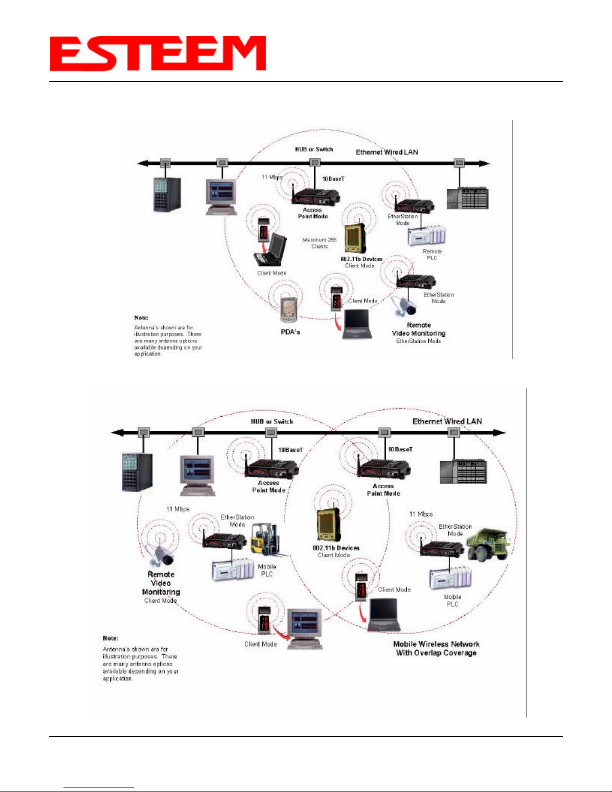
1. Access Point Mode. When the Model 192E is configured as an Access point it will provide a wireless gateway from a
hardwired Local Area Network (LAN) to laptops, office computers, Personal Digital Assistants (PDA’s), video cameras,
PLC’s, etc. that have integral or external 802.11b wireless devices. All Access Points must be physically connected to the
same network (LAN) to provide seamless Ethernet communication for mobile devices.
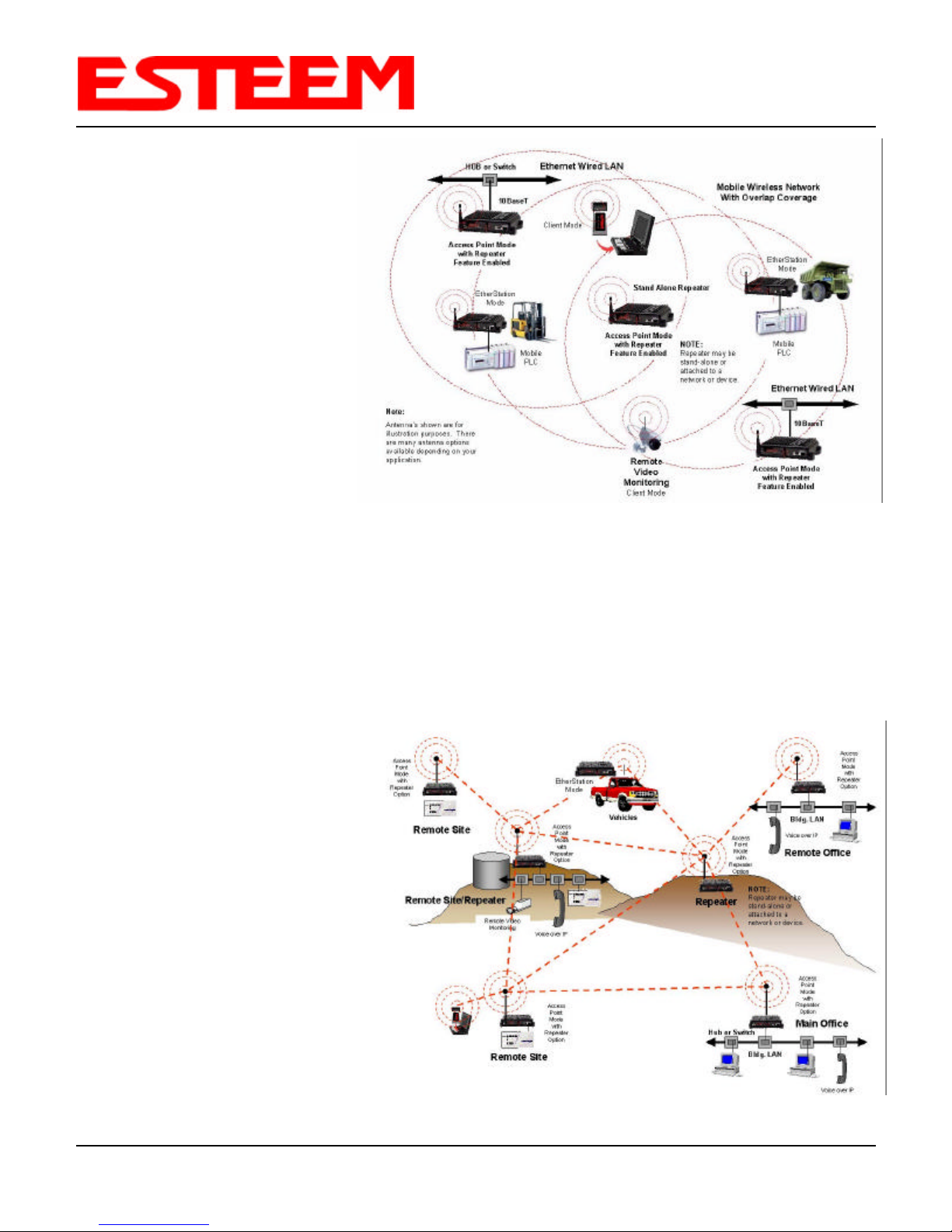
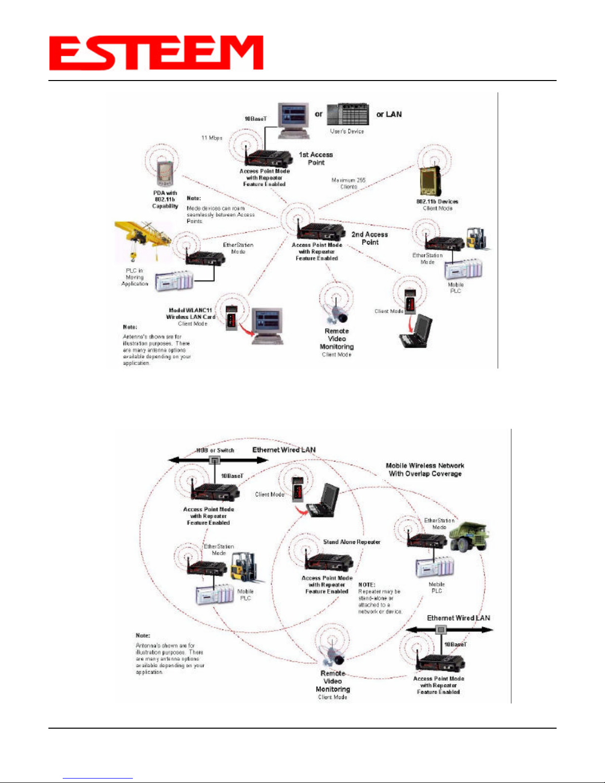
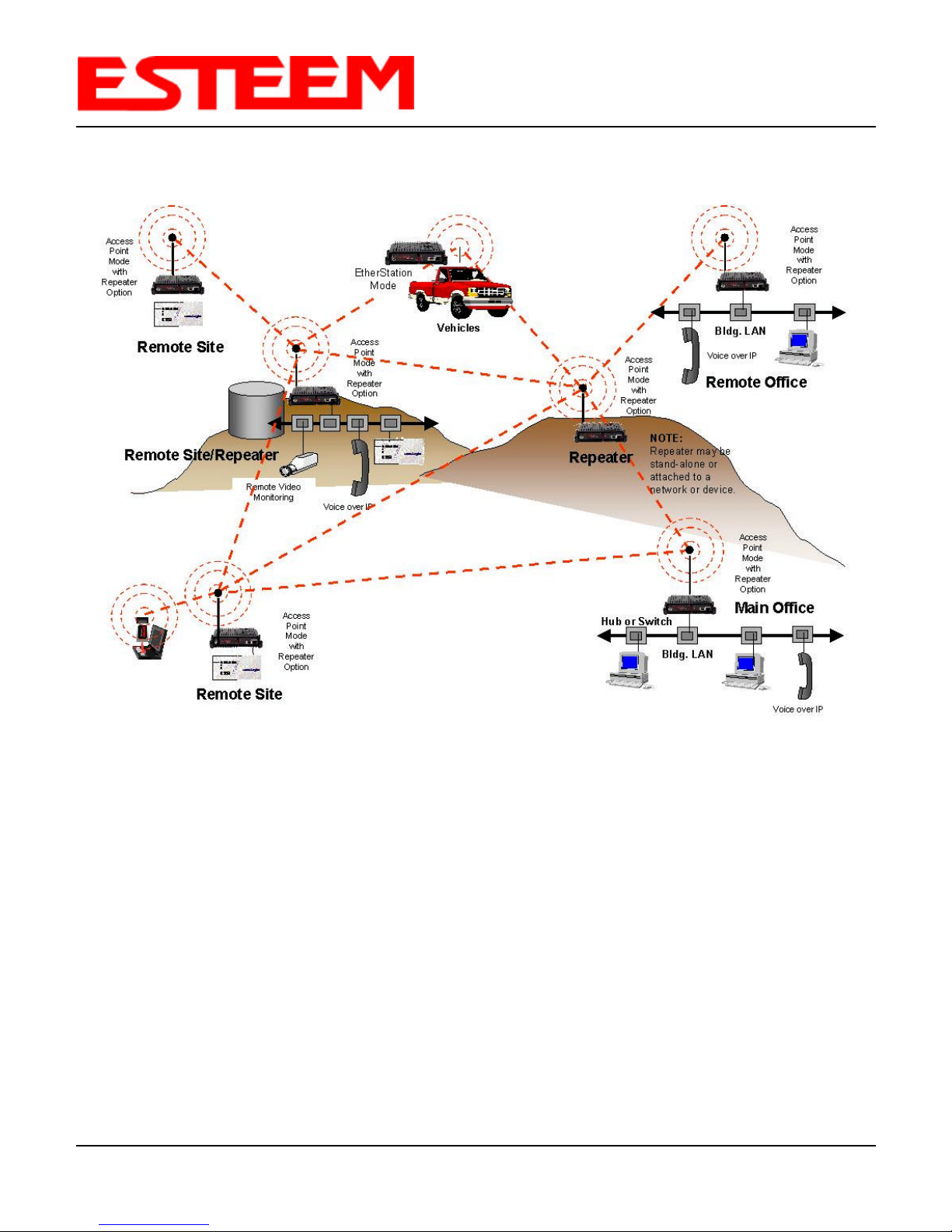
2. Access Point Repeater Mode. The Access Point Repeater is a unique enhancement of the 802.11b Access Point mode
available only in the ESTeem Model 192E. With this feature, The Model 192E Access Points do not have to be hardwired
together on the same physical LAN to provide seamless Ethernet communication for 802.11b devices, but instead
automatically associate with other Model
192Es programmed with the same
configuration (i.e. SSID, Frequency, WEP,
etc.) for routing message traffic over the
wireless Ethernet network. If there are
multiple routes to a destination, this
feature will create a “self-healing” network
by automatically re-routing data through
an alternate path to reach its destination if
the primary path is inoperable. When
programmed in the Access Point Repeater
mode the Model 192Es will also bridge any
Ethernet network or Ethernet device
connected to the unit over this same
wireless Ethernet network. This mode
gives the user the features of a point to
multi-point bridge network but also allows
802.11b devices or the Model 192E in the
EtherStation mode to access the network.
See Figure 2.
Figure 2: Access Point Repeater Mode Diagram
Revised: 16 Oct 03 1-1 EST P/N AA107
Page 9
CHAPTER 1
INTRODUCTION
3. EtherStation Mode. This is a special feature of the Model 192E when used in an Access Point application. When the 192E
is configured in the EtherStation Mode and attached to an Ethernet Device, the Model 192E will emulate an 802.11b
PCMCIA wireless card in functionality for communication to an 802.11b Access Point. This mode can provide greatly
increased range over a Wireless LAN Card for mobile Ethernet devices such as vehicles, forklifts, cranes, etc. See Figures 1
and 2.
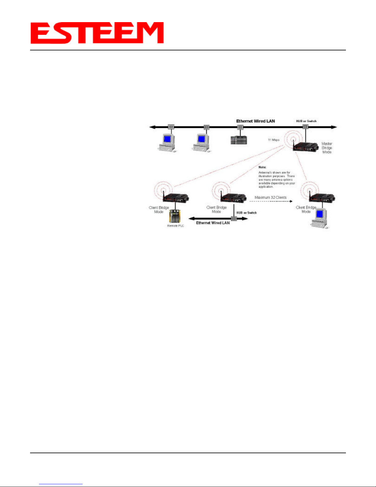
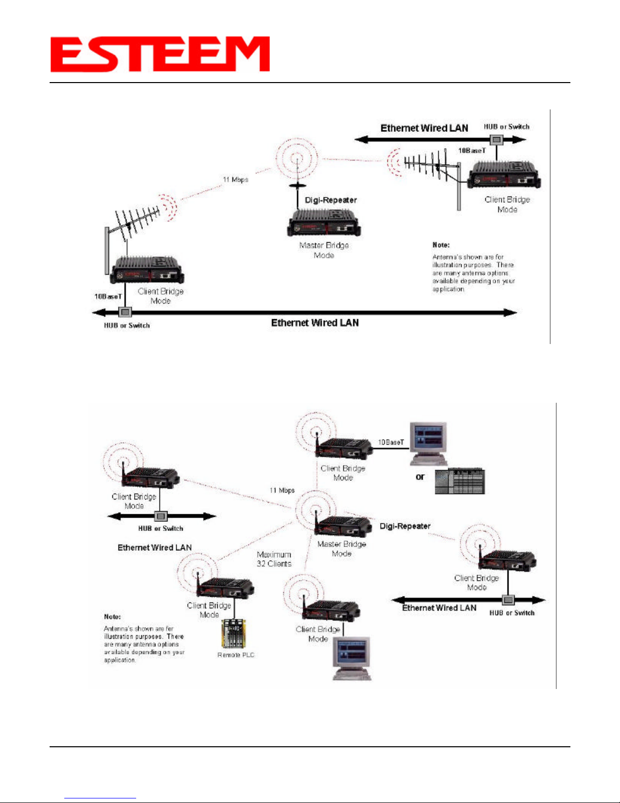
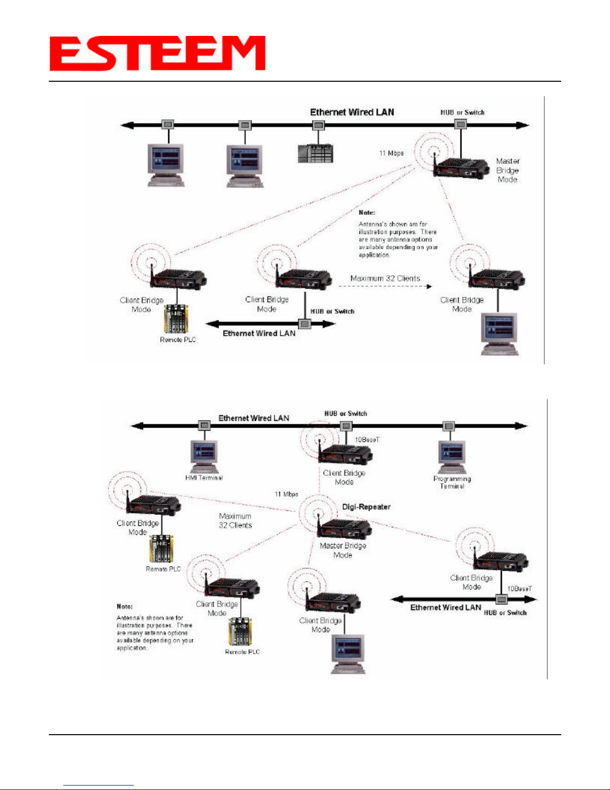
4. Bridging Mode. The Model 192E can be
used to bridge LAN’s and other devices
with an Ethernet port. In this mode the
ESTeem Model 192E will not accept
requests from 802.11b clients. The two
bridge modes available are Master
Bridge and Client Bridge modes. See
Figure 3.
To begin setup of your wireless Ethernet
network you must first select the type of
Model 192E configuration required. Chapter
2 will show hardware diagrams and the
respective program mode that each 192E
should be configured in for that application.
In each example the respective programming
mode for each Model 192E will be shown
under the ESTeem icon. After you have
designed your network, proceed with specific instructions in Chapters 3 & 4 on how to program the 192E for the mode of
operation needed, i.e. Access Point, EtherStation (Access Client), Master Bridge, or Client Bridge Modes.
Figure 3: Point to Multi-Point Ethernet Bridge Diagram
All possible Ethernet network configurations can not be listed. If your application does not match any of the configurations in
Chapter 2, please consult with your network system administrator or contact EST Customer Support at 509-735-9092.
Revised: 16 Oct 03 1-2 EST P/N AA107
Page 10
CONFIGURATION DIAGRAMS
MODEL 192E ACCESS POINT CONFIGURATION DIAGRAMS
CHAPTER 2
Figure 1: Access Point Diagram
Revised: 16 Oct 03 2-1 EST P/N AA107
Figure 2: Multiple Access Point Diagram
Page 11
CHAPTER 2
CONFIGURATION DIAGRAMS
Figure 3: Access Point Diagram with Repeater
MODEL 192E ACCESS POINT REPEATER CONFIGURATION DIAGRAMS
Revised: 16 Oct 03 2-2 EST P/N AA107
Figure 4: Access Point Multiple Repeater Diagram
Page 12
CHAPTER 2
CONFIGURATION DIAGRAMS
Figure 5: Access Point Multiple Repeater Diagram
Revised: 16 Oct 03 2-3 EST P/N AA107
Page 13

MODEL 192E BRIDGE CONFIGURATION DIAGRAMS
CHAPTER 2
CONFIGURATION DIAGRAMS
Figure 6: Point to Point Bridge Diagram
Revised: 16 Oct 03 2-4 EST P/N AA107
Figure 7: Point to Multi-Point Bridge Diagram
Page 14
CHAPTER 2
CONFIGURATION DIAGRAMS
Figure 8: Point to Point Bridge with Repeater Diagram
Revised: 16 Oct 03 2-5 EST P/N AA107
Figure 9: Point to Multi-Point Bridge with Repeater Diagram
Page 15
CHAPTER 2
CONFIGURATION DIAGRAMS
Figure 10: Point to Multi-Point Bridge Diagram
Revised: 16 Oct 03 2-6 EST P/N AA107
Figure 11: Point to Multi-Point Bridge with Repeater Diagram
Page 16

CHAPTER 3
STARTING OUT
Section 3 of the User’s Manual will show basic configuration of the system using the RS-232 port to allow further programming
using the ESTeem Web Page shown in Chapter 4.
When powering up the ESTeem for the first time you must use the ESTeem RS-232C Configuration Menu to setup the basic
operating parameters such as assigning the ESTeem an IP Address, IP Net Mask, Gateway IP Address, Domain Name, and
DNS IP Address. Once the IP address is configured you can communicate to the ESTeem through your web browser.
Any terminal emulation program can be used for this configuration of the ESTeem. Most Windows users will probably use
Hyper Terminal. Configure your RS-232C port for a Baud Rate to 38,400, Data Bits to 8, Parity to None, Stop Bits to 1 and
Handshaking to None. Once your ESTeem has an IP address, can attach the ESTeem to your network and use the Web Server
for further programming.
MODEL 192E HARDWARE LAYOUT
Locate the items contained in Figure 1 for initial configuration of the ESTeem Model 192E. Take a few minutes to inventory your
equipment before you proceed. Report any missing or damaged items to Customer Support (509-735-9092) as soon as possible.
Your ESTeem hardware many
have antennas other then the
AA01S in Figure 1, but you must
have an antenna connected to the
antenna port before applying
power to the unit.
Rubber Duck Antenna
(EST P/N AA01S)
12 VDC Power Supply
(EST P/N AA174)
RS-232C
Programming Cable
(EST P/N AA062)
ESTeem Model 192E
2 Pin Molex
Connector
Figure 1: Model 192E Hardware Layout Diagram
Notes:
• There is no Power On/Off switch on the Model 192E.
• One word of caution please attached an antenna to the Model 192E before power up.
Revised: 16 Oct 03 3-1 EST P/N AA107
Page 17
CHAPTER 3
STARTING OUT
MODEL 192E ESTeem CONFIGURATION
The following steps should be completed before any modifications are made to the network operating parameters for the
ESTeem Model 192E.
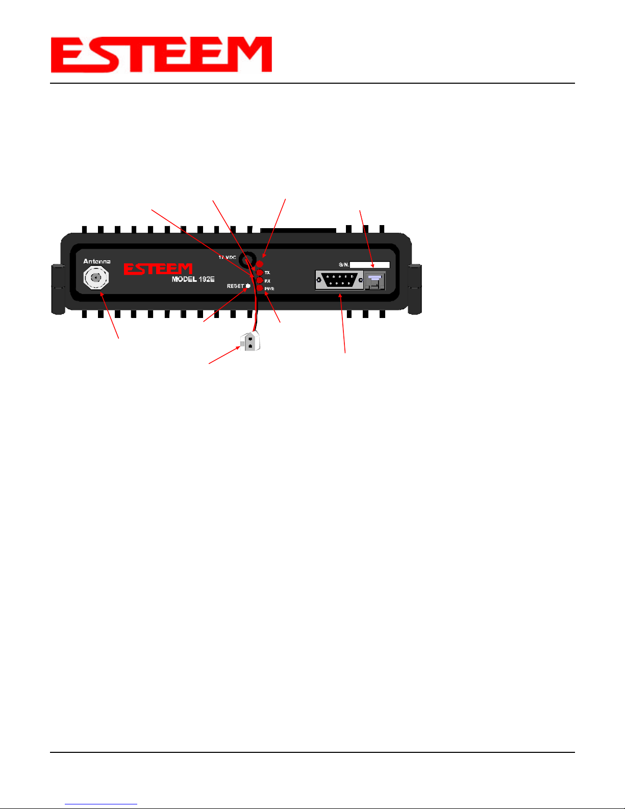
1. Connect the antenna to the antenna connector on the ESTeem Model 192E (Figure 2).
Receive LED
Transmit LED
T/E LED
T/E
RJ-45 10BaseT
Ethernet Port
Notes:
• Configure the Model
192E prior to
mounting.
• Some of the following
steps, such as
connecting the serial
cable, are easier to
perform if the
ESTeem is accessible.
• Please attach an
antenna to the Model
192E before power up.
• There is no Power
On/Off switch on the
Model 192E.
Antenna Connector
(TNC-R)
Reset Switch
12 VDC Input
Power Connector
(2 Pin Molex)
Power LED
RS-232
Programming Port
(9 PinDB Connector)
Figure 2: Model 192E Front Panel Description
2. When powering up the ESTeem for the first time you must use the ESTeem RS-232C Configuration Menu to setup the basic
operating parameters such as assigning the IP Address, IP Net Mask , Gateway IP Address, Domain Name, and DNS IP
Address.
3. Connect the serial cable (EST P/N: AA062) between the RS-232 connector on the ESTeem to the serial port on the computer.
4. Any terminal emulation program can be used for the configuration of the ESTeem. Most Windows users use Hyper
Terminal. Configure your RS-232C port for a Baud Rate to 38,400, Data Bits to 8, Parity to None, Stop Bits to 1 and
Handshaking to None. For information on the Model 192E RS-232 Port see Appendix C.
5. Plug the ESTeem Model AA174 power supply into a wall socket and connect the Molex power connector to the ESTeem.
The power light (PWR) on the front of the ESTeem should be illuminated.
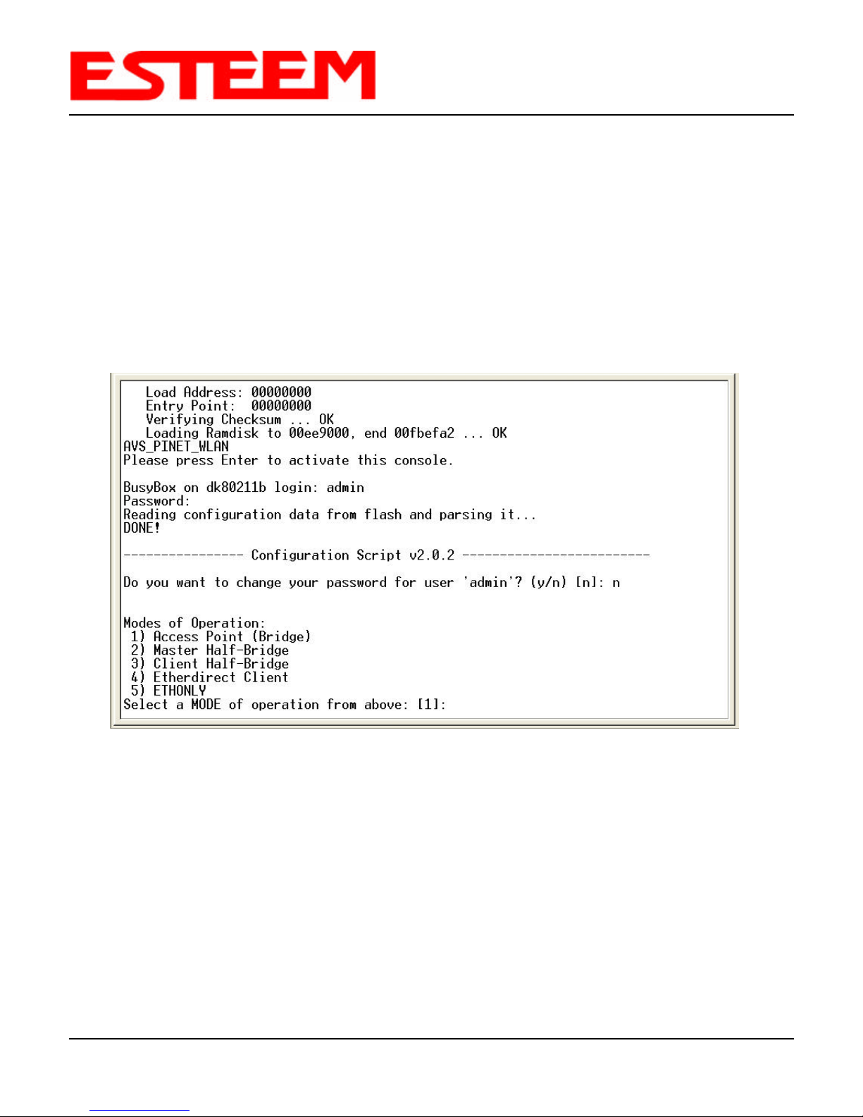
6. If your computer is configured properly, you will see the ESTeem Model 192E booting sequence on your Terminal Emulation
program. See Figure 3.
Once the ESTeem boot sequence is complete (approximately 1 minute) you will receive this message:
“Please press Enter to active this console.”
If you don’t see this message press the Reset button on the front panel of the ESTeem and/or check the programming of
your RS-232 port.
Revised: 16 Oct 03 3-2 EST P/N AA107
Page 18

CHAPTER 3
STARTING OUT
Figure 3: RS-232 Port Boot-Up Screen
7. Press the Enter key and you will be at the Configuration Menu login prompt 192E login. See Figure 4.
Revised: 16 Oct 03 3-3 EST P/N AA107
Figure 4: RS-232 Port Log-in Screen
Page 19
CHAPTER 3
STARTING OUT
8. To enter the Model 192E Main Menu you will need to log into the system with a login name and password.
9. If this is not the first time configuration of the ESTeem, see your network systems administrator for the password.
10. At the 192E login prompt type admin for the login name and press the Enter key (<Enter>). The login name is defined at the
factory and is not changeable by the user. Note that all characters are lower case.
11. If this is the first time the ESTeem has been programmed or the login was not changed from the factory default values, the
factory default password is also admin. Enter admin for the password and press the Enter key (<Enter>). Note: All
characters are lower case.
12. The ESTeem Configuration Menu (Figure 5) will now be displayed.
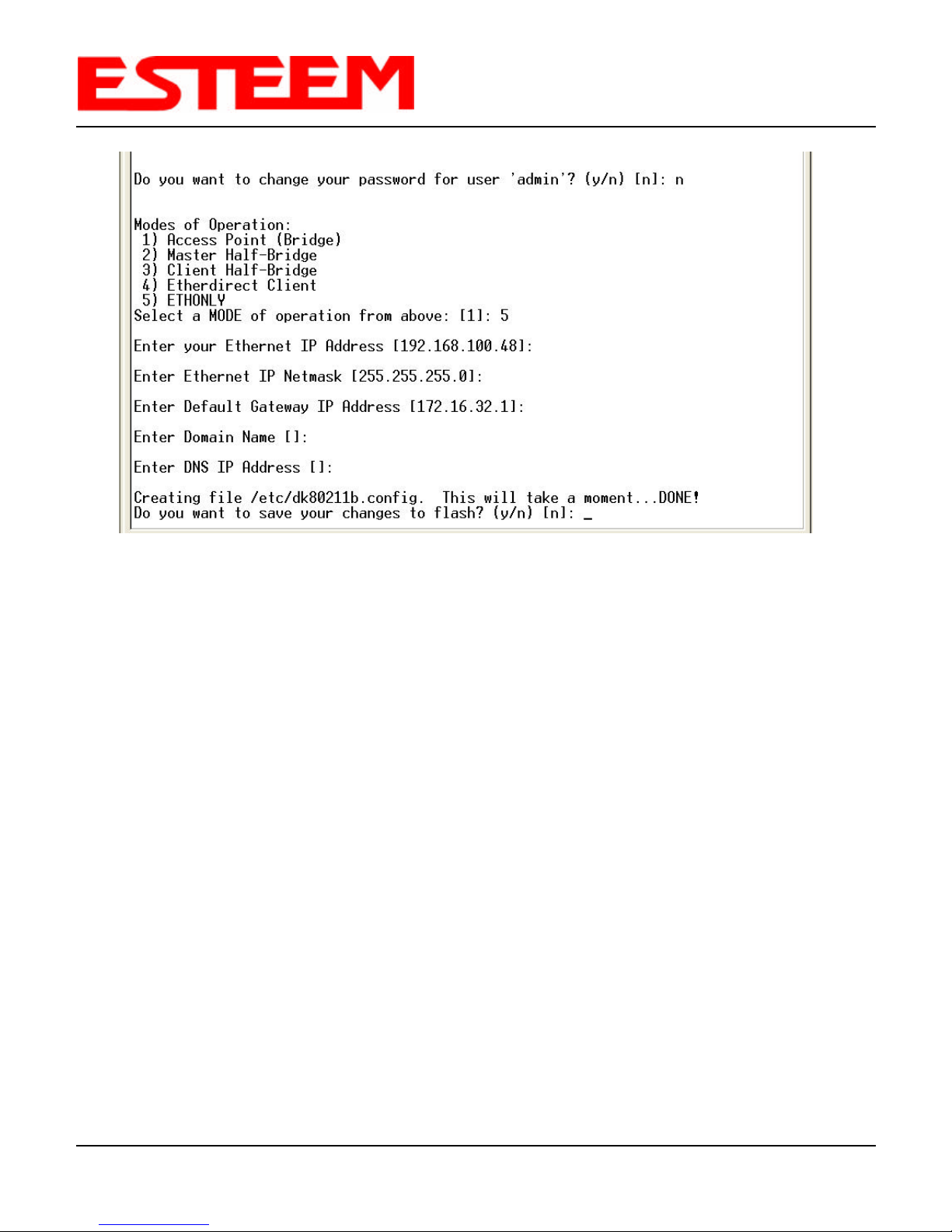
13. Enter 5 for ETHONLY (this stands for Ethernet only configuration mode. You will see the screen in Figure 6. Program the
basic operating parameters such as assigning the ESTeem an IP Address, IP Net Mask , Gateway IP Address, Domain Name,
or DNS IP Address. When you have completed entering the basic operating parameters as required for your application,
answer Yes, to save your changes to flash memory.
14. After the basic parameters have been entered into the ESTeem and the changes saved to flash memory you can use the
higher level programming features in the ESTeem Web Page to configure the unit for your application. To use the ESTeem
Web Page proceed to Chapter 4.
Revised: 16 Oct 03 3-4 EST P/N AA107
Figure 5: RS-232 Main Menu
Page 20
CHAPTER 3
STARTING OUT
Figure 6: Ethonly Screen
Revised: 16 Oct 03 3-5 EST P/N AA107
Page 21
CHAPTER 4
ESTeem WEB PAGE
When powering up the ESTeem for the first time you must use the ESTeem RS-232C Configuration Menu to setup the basic
operating parameters such as
assigning the ESTeem an IP
Address, IP Net Mask , Gateway
IP Address, Domain Name, and
DNS IP Address. This is
necessary to communicate with
the ESTeem using your web
browser. Chapter 3, Starting Out
will provide detailed information
on how this is done.
HARDWARE SETUP
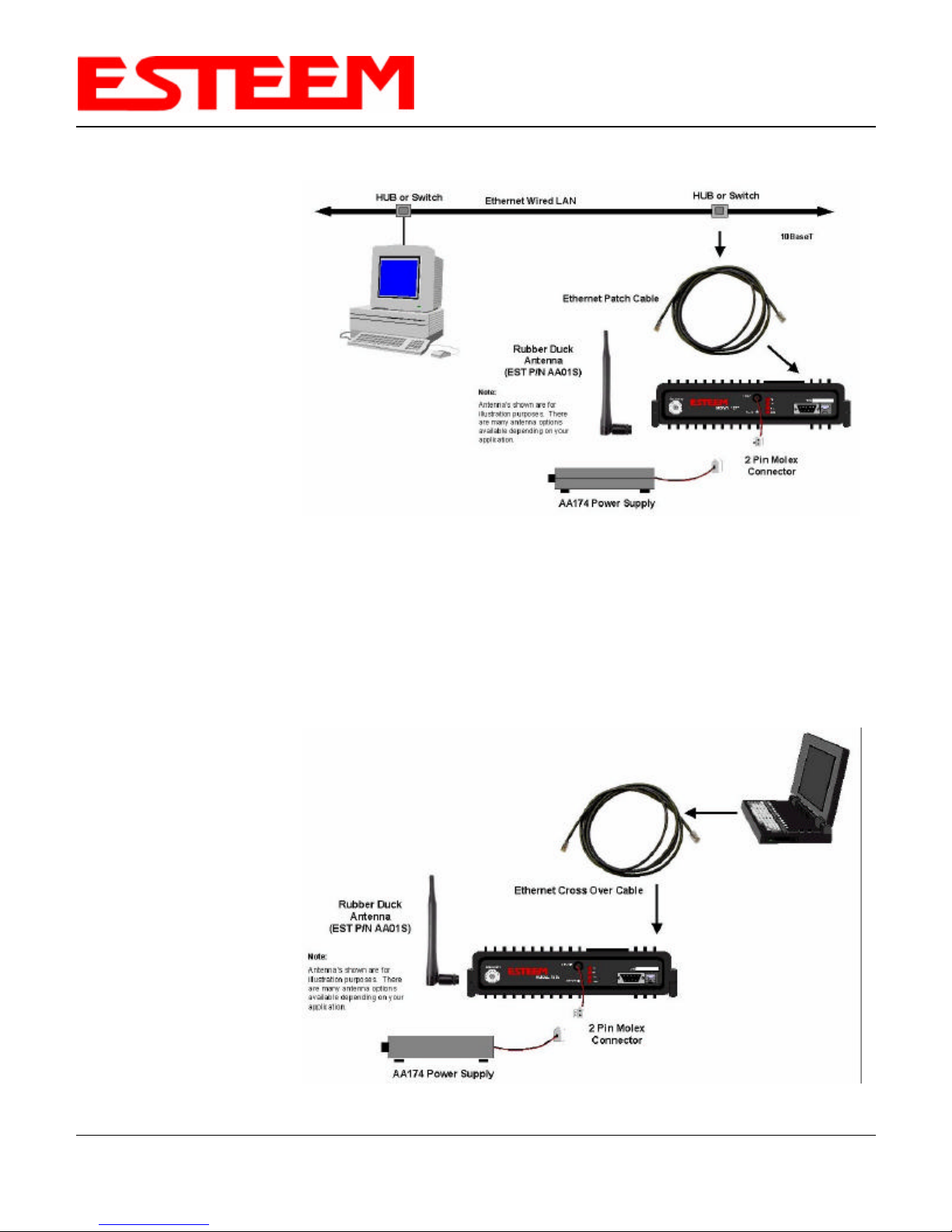
Figure 1 shows a typical
hardware configuration if you are
accessing the ESTeem Web page
from a computer over a hardwired
LAN. The ESTeem Model 192E is
interfaced to the LAN from a Hub
or Switch. Figure 2 shows a
typical hardware configuration if
you are accessing the ESTeem Web page from a computer interfaced directly to the ESTeem Ethernet port.
Figure 1: Hardware Setup Using LAN Ethernet Connection
1. Connect the antenna to the antenna connector on the Model 192E.
2. Plug the ESTeem Model AA174 power supply into a wall socket and connect the Molex power connector to the ESTeem.
The power light (PWR) on the front of the ESTeem should be illuminated.
3. Connect the Ethernet cable to the LAN or computer.
Notes:
• There is no Power On/Off
switch on the Model 192E.
• Please attach an antenna
to the Model 192E before
power up.
• When powering up the
ESTeem for the first time
you must use the ESTeem
RS-232C Configuration
Menu described in Section
3 to setup the basic
operating parameters such
as assigning the IP
Address, IP Net Mask,
Gateway IP Address,
Domain Name, and DNS
IP Address.
Figure 2: Hardware Setup Direct to Computer
Revised: 12 Mar 04 4-1 EST P/N AA107
Page 22
LOGGING ON TO THE ESTeem WEB PAGE
1. Using your Web Browser connect to the Model 192E Web
Page with the IP Address that you have assigned it in Chapter
3.
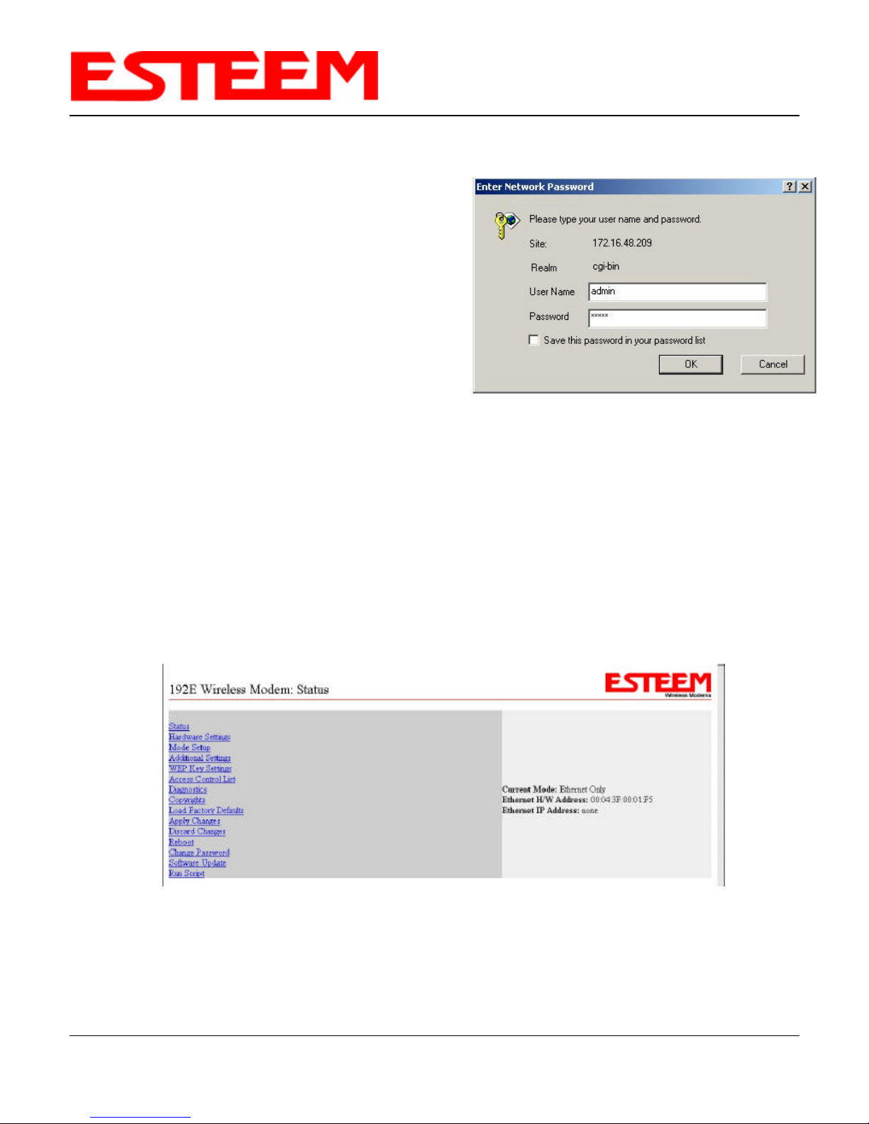
2. You will now see the Log-on Menu on Figure 3. To enter the
Model 192E Status Menu you will need to log into the system
with a login name and password.
3. For the login name enter admin and press the Enter key
(<Enter>). The login name is defined at the factory and is not
changeable.
4. Enter your password and press the Enter key (<Enter>).
If this is the first time the ESTeem has been programmed and
password was not changed from the factory default values,
proceed with the steps below to access the Configuration Menu.
CHAPTER 4
ESTeem WEB PAGE
Figure 3: ESTeem Web Page Log-on Screen
• The factory default password is also admin. Enter admin for the password and press the Enter key (<Enter>).
• Note: All characters are lower case.
5. After Log-in the next screen displayed will be the Model 192E Status Menu page (Figure 4). This example screen shows the
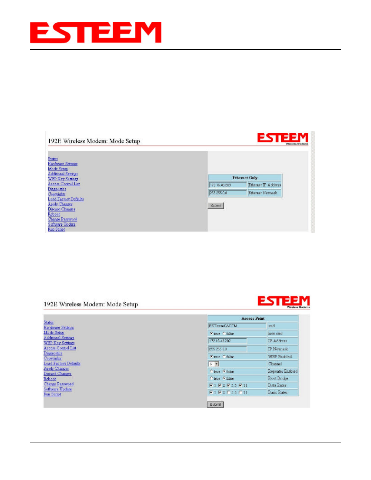
status screen for the Ethernet Only Mode.
Figure 4: Ethernet Only Status Screen
Revised: 12 Mar 04 4-2 EST P/N AA107
Page 23
CHAPTER 4
ESTeem WEB PAGE
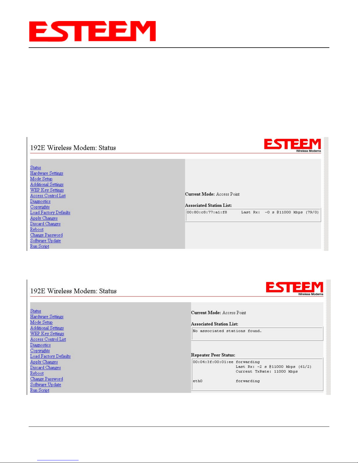
STATUS MENU SCREENS
The ESTeem Web Page Status Menu displays the current mode of operation and status of the communication links to other
wireless devices. The status screen will automatically update at the interval defined in the Auto Refresh setting in the
Additional Settings Menu. The Status Menu lists connected wireless devices (either other Model 192Es or 802.11b clients),
their signal strength, data rate and background noise. An example for each mode is shown below:
Ethernet Only. Figure 4 Access Point Repeater. Figure 6 Client Bridge. Figure 8
Access Point. Figure 5 Master Bridge. Figure 7
Figure 5: Access Point Status Screen
Figure 6: Access Point Repeater Status Screen
Revised: 12 Mar 04 4-3 EST P/N AA107
Page 24
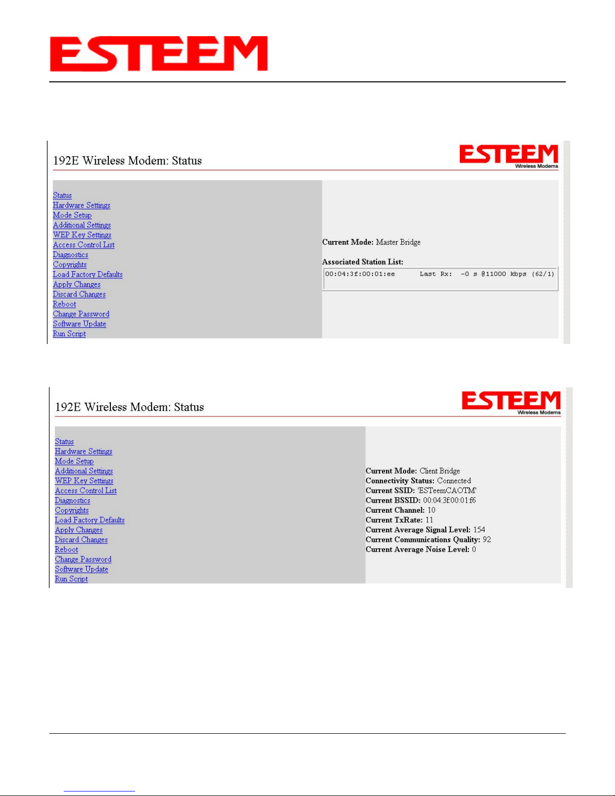
STATUS MENU SCREENS
CHAPTER 4
ESTeem WEB PAGE
Figure 7: Master Bridge Status Screen
Figure 8: Client Bridge Status Screen
Revised: 12 Mar 04 4-4 EST P/N AA107
Page 25
CHAPTER 4
ESTeem WEB PAGE
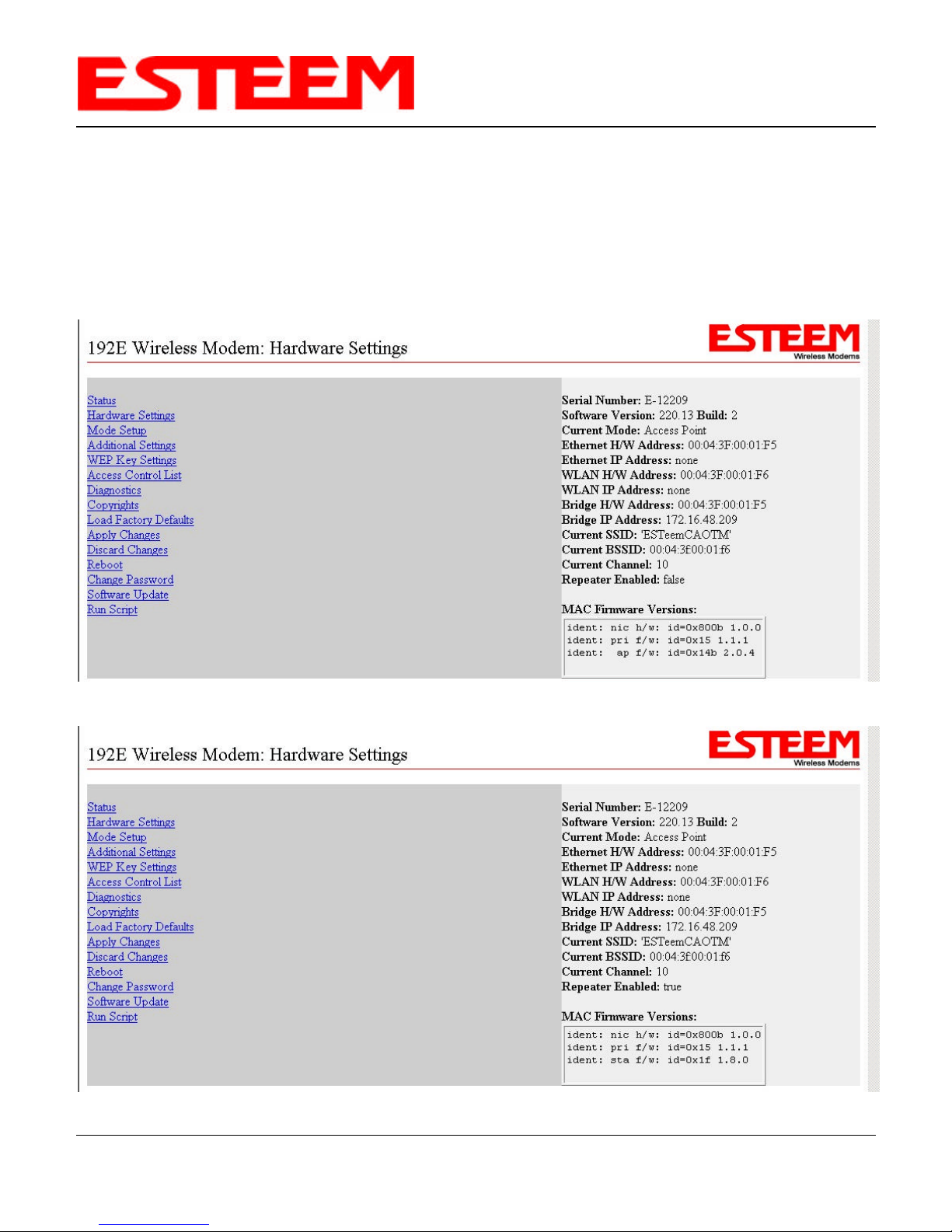
HARDWARE SETTINGS SCREENS
The Hardware Settings Screen contains information such as the serial number, software revision and all network addresses. An
example for each mode of operation is shown below:
Access Point. Figure 9 Master Bridge. Figure 11
Access Point Repeater. Figure 10 Client Bridge. Figure 12
Figure 9: Access Point Hardware Settings Screen
Figure 10: Access Point Repeater Hardware Settings Screen
Revised: 12 Mar 04 4-5 EST P/N AA107
Page 26
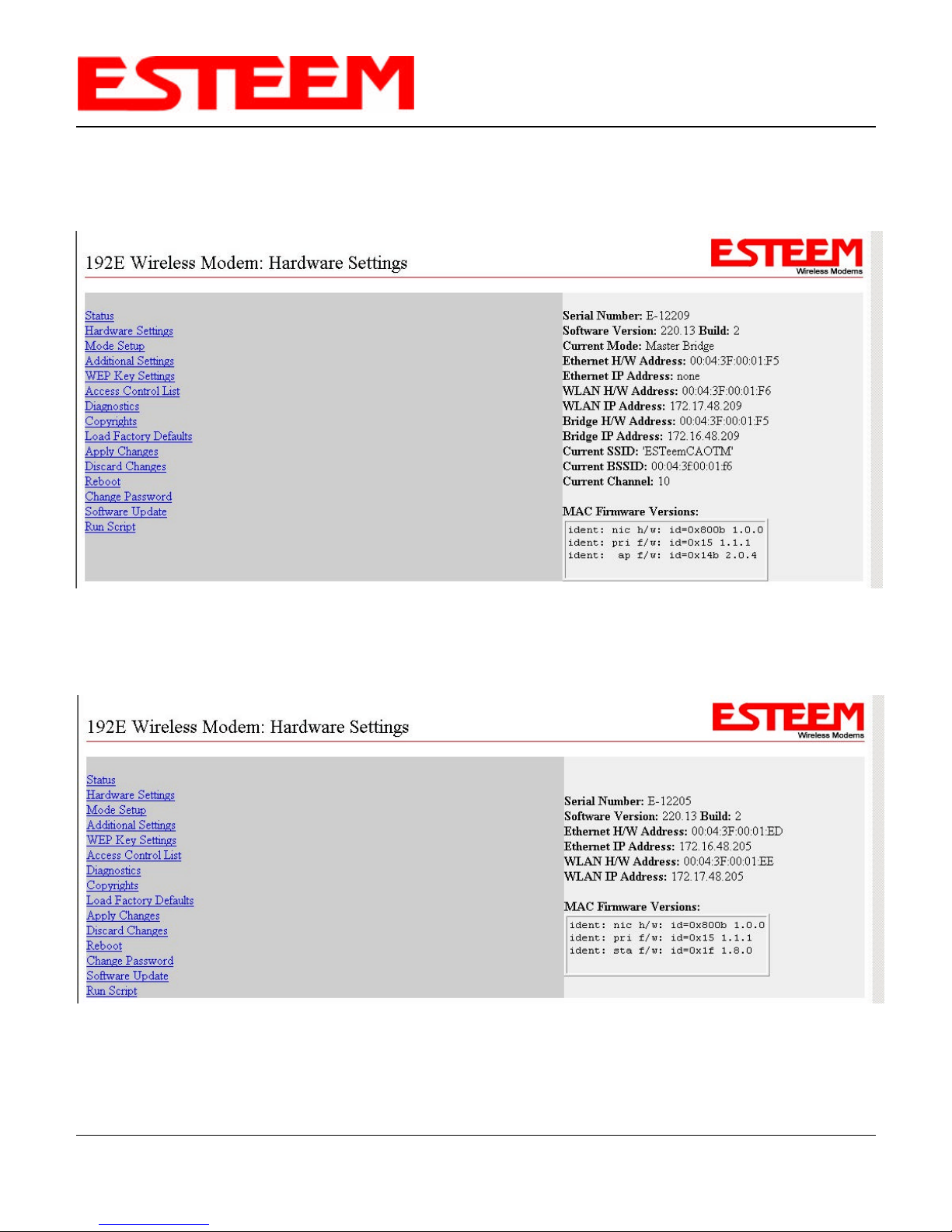
HARDWARE SETTINGS SCREENS
CHAPTER 4
ESTeem WEB PAGE
Figure 11: Master Bridge Hardware Settings Screen
Figure 12: Client Bridge Hardware Settings Screen
Revised: 12 Mar 04 4-6 EST P/N AA107
Page 27
CHAPTER 4
ESTeem WEB PAGE
MODE SETUP SCREENS
The ESTeem Model 192E can be configured in six different modes of operation. Chapter 2 shows examples of site diagrams and
the respective mode of operation for each Model 192E to perform its specific task in that example. Listed below are the six
modes of operation:
Ethernet Only. Ethernet Only is a diagnostic mode that allows updates on the ESTeem without activating the transceiver. The
Mode Setup allows the user to change the Model 192E’s Ethernet IP and Ethernet Netmask addresses. See Figure 13.
Figure 13: Ethernet Only Mode Setup Screen
Access Point. Allows the user to configure the Model 192E in the Access Point mode. Reference Chapter 2 Configuration
Diagrams for examples. The SSID is the unique identification for your wireless network. All 802.11b devices that share a wireless
network MUST have the same SSID code. This identification code is case sensitive and must NOT contain spaces. See
Appendix D for information on setting the Channel (Frequency) and Data Rates. See Figure 14.
Figure 14: Access Point Mode Setup Screen
Revised: 12 Mar 04 4-7 EST P/N AA107
Page 28

CHAPTER 4
ESTeem WEB PAGE
MODE SETUP SCREENS
Access Point Repeater Mode. This mode allows the ESTeem to be placed in the Access Point Repeater mode. Reference
Chapter 2 Configuration Diagrams for examples. The Access Point Repeater is a unique enhancement of the 802.11b Access
Point mode available only in the ESTeem Model 192E. When programmed in Access Point Repeater the Model 192Es will bridge
Ethernet network or Ethernet device connected to the unit over the same wireless Ethernet network as the provided for 802.11b
clients.
In an Access Point Repeater network, all Model 192E’s must be configured with the same SSID, WEP codes and be on the same
frequency channel. If there are more than two Model 192E’s connected in the network, one of them should be configured as the
Root Bridge. See Chapter 5 or further information on selecting the Root Bridge.
Figure 15: Access Point Repeater Mode Setup Screen
Master Bridge. Allows the user to configure the Model 192E in the Bridge Master mode. The Bridging Mode is an ESTeem
proprietary network that will not allow 802.11b device to be used in the wireless network. Reference Chapter 2 Configuration
Diagrams for examples. All Model 192E Ethernet Modems that share a wireless network MUST have the same SSID code. This
identification code is case sensitive and must NOT contain spaces. See Appendix D for information on setting the Channel
(Frequency) and Data Rates. See Figure 16.
Figure 16: Master Bridge Mode Setup Screen
Revised: 12 Mar 04 4-8 EST P/N AA107
Page 29

CHAPTER 4
ESTeem WEB PAGE
MODE SETUP SCREENS
Client Bridge. Allows the user to configure the Model 192E in the Client Bridge mode. Reference Chapter 2 Configuration
Diagrams for examples. All Model 192E Ethernet Modems that share a wireless network MUST have the same SSID code. This
identification code is case sensitive and must NOT contain spaces. The Master Bridge IP Address is the Wireless IP Address
of the Master Bridge. See Appendix D for information on setting the Channel (Frequency) and Data Rates. See Figure 17.
Note: The Ethernet IP Address and Wireless IP Address MUST be on separate IP subnets. Contact you network administrator
for further information on subnets and netmasks. The Master Bridge IP Address is the Wireless IP Address of the Master
Bridge in the network.
Figure 17: Client Bridge Mode Setup Screen
EtherStation. Allows the user to configure the Model 192E in the Etherstation mode. All 802.11b devices that share a wireless
network MUST have the same SSID code. This identification code is case sensitive and must NOT contain spaces. The MAC
address must match the Ethernet device that the ESTeem will be attached. The ESTeem can only service one (1) Ethernet device
when in EtherStation mode. Reference Chapter 2 Configuration Diagrams for examples. See Figure 18.
Note: Once the ESTeem has been saved in EtherStation mode, it can no longer be accessed through the Web Page interface.
To access the modem through the RS-232 interface, refer to Chapter 3.
Figure 18: EtherStation Mode Setup Screen
Revised: 12 Mar 04 4-9 EST P/N AA107
Page 30

CHAPTER 4
ESTeem WEB PAGE
ADDITIONAL SETTINGS SCREEN
The Additional Settings screen allows the user to configure operating parameters in the Model 192E (Figure 19). See the
following list for a definition of terms:
Figure 19: Additional Settings Screen
Default Gateway, Domain Name, and DNS IP addresses set the parameter to allow the ESTeem Model 192E to access update
files directly from the ESTeem web site. See your system administrator for the correct values.
Auto Refresh. The Auto Refresh feature updates the displayed information on the status screen after a specified
amount of time. The time between each refresh is shown in seconds and is user definable from 1 to 999.
A value of –1 will disable the auto refresh feature.
RTS Threshold This feature allows the user to specify the size of data packets that require an additional verification
that the remote ESTeem is ready to receive the packet. Packets above the specified value will trigger the
source ESTeem to contact the receiving unit with a request to send (RTS) data packet. When the
destination ESTeem is ready to receive the data packet, the acknowledge to the RTS is sent back to the
source ESTeem. At this time all other units will cease communications and wait until the data packet is
sent before resuming communication. All packets below the RTS Threshold will be sent directly
without the RTS sync. This feature would be used when two or more remote sites are communicating
with each other through a repeater site and are unable to “hear” the transmissions directly. The RTS
Threshold will allow a remote Model 192E to quiet all others users before larger data packets are sent.
Revised: 12 Mar 04 4-10 EST P/N AA107
Page 31

CHAPTER 4
ESTeem WEB PAGE
ADDITIONAL SETTINGS SCREEN
Packet sizes
Off 2347 bytes
Lg. 1760 bytes
M-Lg. 1174 byes
M-Sm. 587 bytes
SM 0 bytes (Every Packet)
Radio Power This feature sets the output power of the Model 192E. The following chart are the approximate output
power levels for each setting.
Max (Maximum) 1 Watt
Hi (High) 500 mw
Lo (Low) 250 mw
Min (Minimum) 100 mw
The Transceiver configuration
Programmed (On/Off). This command will allow the user to program the ESTeem radio transceiver On or Off. This feature
must be saved to be permanent. The normal (default) setting is On.
Toggle (On/Off). This command allows the user to toggle the transceiver On or Off immediately from the setup screen
shown regardless of the programmed setting of the Programmed command. If the unit has been
powered off, the radio transceiver will be turned On or Off dependent on the prior programmed state of
the Programmed command.
Radio Toggle
TX (On/Off). This command allows the user to toggle the transmitter On or Off for measurement of the output power
and SWR testing of the antenna. When the transmitter is toggled On the Model 192E will continue to
transmit until toggled Off.
Remote (On). This command allows the user to toggle the transmitter On for remote measurement of receive signal
strength with a spectrum analyzer. When the remote transmitter is toggled On the Model 192E will
transmit for 20 seconds then turn off. While the transmitter is on, the communication to the modem is
down but will return after the 20 seconds.
Spanning Tree Protocol (STP) (On/Off). Setting the STP to Off disables the ability of the modem to prevent network loops
when configured for Access Point Repeater Mode (see Chapter 5 for further details). It should only be
set to Off in specific applications where the modems need to transmit packets that it normally drops.
For example, Rapid Spanning Tree Protocol (RSTP) packets are dropped by the modem unless STP is
disabled. Networks that need the modems to transmit the RSTP packets must ensure the modems do
not create loops. Two Access Point repeaters connected to the same network via the Ethernet port
would be an example of a network loop.
Revised: 12 Mar 04 4-11 EST P/N AA107
Page 32

ESTeem WEB PAGE
WEP KEY SETTINGS SCREEN
WEP Key Settings screen allows the user to define the encryption keys. See Figure 20.
CHAPTER 4
Figure 20: WEP Key Settings Screen
ACCESS CONTROL LIST (ACL) SCREEN
The ACL is one of the simplest yet most secure methods of network security. The ACL is a configurable MAC filter in the
Model 192E that can be set to allow specific MAC address on the wireless network by individual address or address ranges
(Figure 21). The filter can also be set to reject individual MAC addresses or address ranges (Figure 22). The maximum number
of address that can be entered is 60.
The MAC address is a unique, 6 hexadecimal field address assigned at the manufacturer that can not be changed. The MAC
address is traceable through the IEEE governing body to the manufacturer and is the “fingerprint” for all Ethernet devices.
Using a combination of both the 128-Bit WEP encryption and the ACL filter provide the ESTeem an extremely secure wirelessnetworking layer.
Revised: 12 Mar 04 4-12 EST P/N AA107
Figure 21: Access Control List Allow
Page 33

ESTeem WEB PAGE
Allow All: Allows all MAC addresses to access network
Deny All: Denies all MAC addresses access to network
Allow ACL: Allows only specific MAC addresses or address ranges access to the network
Deny ACL: Denies specific MAC addresses or address ranges access to the network
CHAPTER 4
Figure 22: Access Control List Deny
DIAGNOSTICS SCREEN
Figure 23: Diagnostics Screen
The Diagnostics screen is a trouble shooting tool that shows the current log of Model 192E system messages. See Figure 23.
Revised: 12 Mar 04 4-13 EST P/N AA107
Page 34

ESTeem WEB PAGE
COPYRIGHTS SCREEN
The Copyrights screen has links to major software contributor’s web sites. See Figure 24.
Figure 24: Copyrights Screen
CHAPTER 4
LOAD FACTORY DEFAULTS SCREEN
The Load Factory Defaults screen allows the user to load the factory defaults into the Model 192E. See Figure 25.
Figure 25: Load Factory Defaults Screen
Revised: 12 Mar 04 4-14 EST P/N AA107
Page 35

ESTeem WEB PAGE
APPLY CHANGES SCREEN
Apply Changes Screen saves the program changes to the internal memory of the 192E. See Figure 26.
Figure 26: Apply Changes Screen
CHAPTER 4
DISCARD CHANGES SCREEN
Discard Changes deletes the software changes made to the Model 192E during your current session if the changes have not
been saved. See Figure 27.
Figure 27: Discard Changes Screen
Revised: 12 Mar 04 4-15 EST P/N AA107
Page 36

CHAPTER 4
ESTeem WEB PAGE
REBOOT SCREEN
Allows the User to Reboot the CPU of the Model 192E. This is identical to rebooting the ESTeem via the front panel switch.
See Figure 28.
Figure 28: Reboot Screen
CHANGE PASSWORD SCREEN
The Change Password screen allows the user to change the password for entering the Administration section of the Model
192E. See Figure 29.
Figure 29: Change Password Screen
Revised: 12 Mar 04 4-16 EST P/N AA107
Page 37

CHAPTER 4
ESTeem WEB PAGE
SOFTWARE UPDATE PROCEDURE
The Software Update feature allows the user to update the latest 192E operating system software from the factory via the
Ethernet port to the Model 192E’s flash memory. See Figure 30.
Figure 30: Software Update Screen
The software update can be completed through a local FTP Server connected to the wireless network or from the ESTeem Web
Site if the Model 192E is connected to a network that has an Internet gateway. The update can be completed from or to any
ESTeem Model 192E on the wireless network. Please select the type of update that will function best for your application and
proceed with the update.
Local FTP Server
1. Configure an FTP server on the network where the ESTeem Model 192E is connected. Verify that you have the Username
and Password required to access the FTP server before proceeding.
2. Download the latest update image from the ESTeem FTP Site (ftp://www.esteem.com/192E ). Please contact ESTeem
technical support at 509-735-9092 for information on the latest update file name or refer to web site for the latest version.
3. In the Update URL field on the Software Update Screen (Figure 30) input the following command string:
ftp://<Username> :<Password>@<IP Address of FTP Server>/<Directory of Update File>/<Update File Name>
Example: ftp://User :Password@172.16.1.1/FTP/swupdate-220.13.img
4. The ESTeem will find the update file and begin the update procedure. The update will go through three stages
(Downloading, Validating Update and Writing) and will display the status screen seen in Figure 31.
5. When the Update Complete screen appears (Figure 32) after a few minutes, the last step is to press the Reboot button to
complete the update. The ESTeem may need to be reconfigured for operation, depending upon the mode of operation that
was selected before the update. Verify the setup by selecting Mode Setup and complete the setup procedure.
Revised: 12 Mar 04 4-17 EST P/N AA107
Page 38

CHAPTER 4
ESTeem WEB PAGE
Figure 31: Software Download Screen
Figure 32: Update Complete Screen
Using the ESTeem Web Site
The update procedure for updating from the ESTeem web site is almost identical to using a local FTP server.
1. Verify that the Internet Gateway computer information is listed in the 192E Additional Setting Page (Figure 16) under 192E
Default Gateway, Domain Name, and DNS IP addresses. Contact your network administrator for these addresses.
2. Obtain the latest update image file name from ESTeem Customer Support at 509-735-9092 or your software update e-mail
announcement. In the Update URL field on the Software Update Screen (Figure 30) input the following command string:
ftp://www.esteem.com/192e/<Update File Name>
3. Follow steps 4 and 5 in the above procedure to complete the update.
Revised: 12 Mar 04 4-18 EST P/N AA107
Page 39

CHAPTER 4
ESTeem WEB PAGE
RUN SCRIPT SCREEN
The Run Script Screen allows the user to update specific sections of the Model 192E software without completing a complete
software update. If asked from technical support to run a script file, you will input the name of the script file in the Script URL
box (Figure 33) in the same way you input the Software Update file. Review Software Update Screen above for more
information.
Figure 33: Run Script Screen
Revised: 12 Mar 04 4-19 EST P/N AA107
Page 40

Page 41

ACCESS POINT REPEATER MODE
To increase the wireless network area of coverage for
both indoor and outdoor applications with a convential
IEEE 802.11b Access Point (AP) all of the APs have to be
interfaced to a common network either by hardwire, see
Figure 1, or a dedicated point to point RF backbone.
CHAPTER 5
The Model 192E with the Access Point Repeater Feature
allows the user to cover large areas both indoor and outdoor without the added expense of hard cabling or adding an additional
point to point radio link. The Access Point Repeater Mode in the Model 192E is a custom feature offered by ESTeem. When
programed in the AP Repeater Mode, the Model 192E will automatically create a wireless network with other Model 192E units in
radio range that are programmed in AP Repeater mode with a matching configuration. This feature will also add the increased
functionality of repeaters to the typical Ethernet Bridge configuration.
Figure 1: Access Point Diagram
Auto-Routing
One of the most powerful features of the AP
Repeater mode is the Model 192E’s ability to
automatically calculate all possible
communication routes in the network. The
autoroute feature will automatically establish
wireless Ethernet communication paths to each
ESTeem that has a matching configuration. This
automatic routing greatly simplifies network
configuration and also creates a “self healing”
network by sending data on an alternate route if
the primary path fails.
Auto-Routing Process
Listening Phase - Once a modem is configured
for Access Point Repeater mode and reset, the
Model 192E will begin to search out all modems
that have a matching configuration (SSID, Frequency Channel, AP Repeater Mode = ON and WEP Codes). The first step in the
routing process is sending out and listening for “repeater beacons”. A repeater beacon is a special radio packet that is sent
from the Model 192E that contains the ESTeem’s MAC address. When a repeater beacon is received by another Model 192E,
the MAC address of the originating modem is added to its own repeater beacons. A route between two Model 192Es can be
established when they receive a repeater beacon that contains their own address.
Figure 2: AP Repeater Example
As an example let’s look at Figure 2 and the repeater beacons and the route created from Pump Site C and Tank Site B(Repeater).
Pump Site C sends a repeater beacon containing its MAC address over the radio network. The only site that receives this
repeater beacon is Tank Site B (Note – No Line-of-sight (LOS) between from Pump Site C to the other sites in the network).
When Tank Site B receives the repeater beacon it adds the MAC address from Pump Site C to its own repeater beacon and
sends it out. This new repeater beacon from Tank Site B (Now containing Pump Site C’s MAC address) is received at Pump Site
C and a route is established. Pump Site C then adds the MAC address for Tank Site B in its repeater beacon, which is eventually
received by Tank Site B.
Repeater beacons will continually be sent from a Model 192E every 2 seconds as long as it is configured in AP Repeater mode.
This will allow the Model 192E to recognize new sites into the network and any changes to the radio paths. This continued
updates in the repeater beacon give the AP Repeater network the “self-healing” characteristic.
Revised: 16 Oct 03 5-1 EST P/N AA107
Page 42

CHAPTER 5
ACCESS POINT REPEATER MODE
Learning Phase - When no further routes are added to the repeater beacons in a period of time (approx. 10 seconds), the Model
192E goes into the learning phase. In this phase all Model 192E’s calculate their routes to the other Model 192E’s in the network
using the lowest “path cost” back to the Root Bridge. Note: The Root Bridge in a network should be the Model 192E where
the majority of the data flow is processed. In Figure 2, the Root Bridge will be the Water Plant that is transmitting and receiving
data from all three remote sites. The Root Bridge can be defined by the user, if not defined and there are multiple candidates the
ESTeems in the network will pick the unit with the lowest MAC address. See the following section on Root Bridge for further
details.
Blocking and Forwarding Phase - This last phase in the auto-routing process will eliminate any Ethernet data “loops” that can
double the information received at any remote site. For example, looking at Figure 2, Pump Site D has two routes to the Root
Bridge (Water Plant – Site A); direct from the Water Plant (with a marginal RF link corrected in the following section on using
the ACL in Network Design) and Tank Site B the repeater. The direct link between the two sites is the shortest route (lowest
Path Cost) and will be selected as the primary route (Forward). The longer of the two routes (higher Path Cost) that uses the
repeater will be Blocked. All routes to the Root Bridge will be evaluated and be Forwarded or Blocked. The average time to
complete all routing phases in a network is approximately 30 seconds.
Root Bridge
Any Access Point Repeater application that has more than two sites, needs to set one of the Model 192E’s as the Root Bridge.
The Root Bridge should be the Model 192E where the majority of the Ethernet data flow is processed. This site may be the
Master location in a SCADA network or could be configured at a repeater site. Selection is important because, all the Model
192E’s that are NOT configured as the Root Bridge will select their routing based upon where the Root Bridge is in the network.
If you have any question as to which site in your AP Repeater application should be the Root Bridge, contact ESTeem Customer
Support at 509-735-9092 or e-mail your application to support@esteem.com .
The Root Bridge will be selected in one of two ways: the Root Bridge can be manually set (recommended) in the configuration at
AP Repeater mode (Chapter 4 – AP Repeater Configuration) or the Root Bridge will be the lowest MAC address of all the Model
192E’s in the network. It is not advised to allow the Model 192E’s to select the Root Bridge by address, because adding a new
site to the network could adversely change the entire site’s routing.
Using Access Control List (ACL) In Network Design
As mentioned above, the shortest route to the Root Bridge may not be the
best radio path. As seen in Figure 2 the radio path from Pump Site D to the
Water Plant – Site A has a marginal link. Although the shortest route from
Pump Site D to the Water Plant is direct, the best radio path is using the
repeater site at Tank Site B. To force the radio path through the repeater is
as simple as setting the ACL to Deny the communication link to the Water
Plant (see Chapter 4 – Setting ACL for further details). To complete this
operation, set the Deny ACL button (Figure 3) and enter the MAC address
of the Water Plant. The only other possible route to access the Root Bridge
will be through the repeater site at Tank B.
Figure 3: ACL Configuration Example
Revised: 16 Oct 03 5-2 EST P/N AA107
Page 43

ACCESS POINT REPEATER MODE
Redundant Backup
The ESTeem Model 192E configured in Access Point
Repeater mode will automatically function as a redundant
backup if two Model 192E’s are installed at the same
location (Figure 4). If two Model 192E’s are connected to
the same HUB or Switch, one of the Model 192E’s will be
Blocked when the auto-routing process is completed. The
network will continue to use this route until any problem
with the original Model 192E is detected and the second
Model 192E will begin operation at that site.
Redundant Master Configuration – The configuration in
Figure 4 will also provide a redundant backup for the
Master Site (Root Bridge). Configure both Model 192E’s as
the Root Bridge and the radio with the lowest MAC address
will be the Primary Root Bridge until a problem occurs.
CHAPTER 5
Figure 4: Redundant Backup Diagram
Revised: 16 Oct 03 5-3 EST P/N AA107
Page 44

CHAPTER 6
PROGRAMMING EXAMPLES
PROGRAMMING EXAMPLES
If you are not experienced with programming the Model 192E then review Chapter 2 of this manual to find a site diagram that is
representative of your application. Listed in this chapter we will give you an overview programming the most common uses of
the Model 192E, as a wireless Access Point to a hardwired LAN, Access Point with Repeater Enabled, point to point LAN
Bridge application and using the Model 192E as an EtherStation client. In these examples we will program the ESTeem from the
unit’s Web Page.
Figure 1: Access Point Diagram
Access Point
1. From Chapter 2 review the Access Point diagram. See Figure 1.
2. The ESTeem Model 192E interfaced to the Hub or Switch in the picture will be configured as a wireless Access Point to the
hardwired LAN. This Model 192E will have to be programmed in the Access Point Mode. In this mode the Model 192E will
serve as the base node for 802.11b clients, but will not communicate between other Model 192E in Access Point mode.
3. If you have not defined the IP address of the ESTeem then follow the instructions in Chapter 3.
4. Access the ESTeem Web page using your computer’s Web Browser as per instructions in Chapter 4 under Logging On To
the ESTeem Web Page.
Revised: 15 Mar 04 6-1 EST P/N AA107
Page 45

CHAPTER 6
PROGRAMMING EXAMPLES
5. From the ESTeem Status Screen select Mode Setup. From the Mode pull down box select Access Point and push the select
button below the pull down box. You will now see the screen shown in Figure 2.
Figure 2: Access Point Setup Screen
6. Enter the SSID for you 802.11b network. The SSID is the unique identification for your wireless network and all 802.11b
devices that share a wireless network MUST have the same SSID code. This identification code is case sensitive and must
NOT contain spaces.
7. Select if you would like to hide the SSID from broadcasting from the Access Point. If set to True, the ESTeem will not send
out periodic SSID radio beacons that can be identified with 802.11b network scanning software. The users of the network
will have to know the SSID to enter the network and security is increased, but if you with for the SSID to be broadcast to the
network for easy identification then set to False.
8. Enter the IP Address and IP Netmask for the ESTeem. If you want to be able to access the ESTeem over the Ethernet
network for diagnostics and updates the IP address must be on the same network as the other Ethernet devices.
9. The Model 192E can support up to 128-bit Wired Equivalent Privacy (WEP) encryption. If you will be using encryption in
your network, select WEP Enabled to True. It is recommended that you use encryption on all 802.11b networks to eliminate
unauthorized users from entering the wireless network.
Revised: 15 Mar 04 6-2 EST P/N AA107
Figure 3: WEP Settings Screen
Page 46

CHAPTER 6
PROGRAMMING EXAMPLES
10. Select the frequency channel of operation and data rates. See Appendix D for information on setting the Channel
(Frequency) and Data Rates configuration.
11. Make sure that both Repeater Enabled and Root Bridge are set to False and push the Submit button. If you have set WEP
Enabled to True then you will get the screen shown in Figure 3. Enter in the respective Key values and press the Submit
button.
12. You will see a message at the bottom of the configuration box that the “Values Accepted”(Figure 4). If you have WEP
Enabled set to False, you will receive the same “Values Accepted” message at the bottom of the configuration box when you
Figure 4: Values Accepted Message
press the Submit button.
13. Select Apply Changes on the left-hand side of the screen and then the “Yes, Apply” button to complete the configuration.
The ESTeem will now save all the parameter changes and reboot (Figure 5). After the modem saved the parameters and
rebooted, the Status Screen will be displayed and the ESTeem will be ready for operation in Access Point mode.
Revised: 15 Mar 04 6-3 EST P/N AA107
Figure 5: Modem Rebooting Screen
Page 47

CHAPTER 6
PROGRAMMING EXAMPLES
Access Point Repeater Mode
1. From Chapter 2 review the Access Point Repeater diagram. See Figure 5 shown below.
2. Each ESTeem Model 192E interfaced to the Hub or Switch or the Stand Alone Repeater in Figure 6 will be configured in
Access Point Repeater Mode. This mode will allow Ethernet communication between networks while concurrently
providing access to 802.11b clients.
3. If you have not defined the IP address of the ESTeem then follow the instructions in Chapter 3.
4. Access the ESTeem Web page using your computer’s Web Browser as per instructions in Chapter 4 under Logging On To
the ESTeem Web Page.
Revised: 15 Mar 04 6-4 EST P/N AA107
Figure 6: Access Point Repeater Diagram
Page 48

CHAPTER 6
PROGRAMMING EXAMPLES
5. From the ESTeem Status Screen select Mode Setup. From the Mode pull down box select Access Point and push the select
button below the pull down box. You will now see the Mode Setup screen shown in Figure 7.
6. Enter the SSID for you Access Point Repeater network. The SSID is the unique identification for your wireless network and
all 802.11b devices and Model 192Es that share a wireless network MUST have the same SSID code. This identification
Figure 7: Access Point Repeater Setup Screen
code is case sensitive and must NOT contain spaces.
7. Select if you would like to hide the SSID from broadcasting from the Access Point. If set to True, the ESTeem will not send
out periodic SSID radio beacons that can be identified with 802.11b network scanning software. The users of the network
will have to know the SSID to enter the network and security is increased, but if you with for the SSID to be broadcast to the
network for easy identification then set to False.
8. Enter the IP Address and IP Netmask for the ESTeem. If you want to be able to access the ESTeem over the Ethernet
network for diagnostics and updates the IP address must be on the same network as the other Ethernet devices.
9. The Model 192E can support up to 128-bit Wired Equivalent Privacy (WEP) encryption. If you will be using encryption in
your network, select WEP Enabled to True. It is recommended that you use encryption on all 802.11b networks to eliminate
unauthorized users from entering the wireless network.
10. Select the frequency channel of operation and data rates. See Appendix D for information on setting the Channel
(Frequency) and Data Rates configuration.
Revised: 15 Mar 04 6-5 EST P/N AA107
Figure 8: WEP Settings Screen
Page 49

CHAPTER 6
PROGRAMMING EXAMPLES
11. Set the Repeater Enabled to True (Figure 7). If the Model 192E is going to be used as the Root Bridge set “Root Bridge” to
True and push the Submit button (See Chapter 5 for selecting the Root Bridge).
12. If you have set WEP Enabled to True then you will get the screen shown in Figure 8. Enter in the respective Key values and
press the Submit button.
14. You will see a message at the bottom of the configuration box that the “Values Accepted”(Figure 9). If you have WEP
Enabled set to False, you will receive the same “Values Accepted” message at the bottom of the configuration box when you
Figure 9: Values Accepted Message
press the Submit button.
15. Select Apply Changes on the left-hand side of the screen and then the “Yes, Apply” button to complete the configuration.
The ESTeem will now save all the parameter changes and reboot (Figure 10). After the modem saved the parameters and
rebooted, the Status Screen will be displayed and the ESTeem will be ready for operation in Access Point Repeater mode.
16. Repeat Steps 5 - 14 for each Access Point Repeater in the system.
Revised: 15 Mar 04 6-6 EST P/N AA107
Figure 10: Modem Rebooting Screen
Page 50

PROGRAMMING EXAMPLES
Point to Point Bridge Mode
1. From Chapter 2 review the Point to Point Bridge diagram. See Figure 11 shown below.
CHAPTER 6
Figure 11: Point to Point Bridge Diagram
2. As shown in Figure 11 one of the ESTeems will be programmed in the Master Bridge Mode and the second ESTeem in the
Client Bridge Mode.
3. If you have not defined the IP address of the ESTeems then follow the instructions in Chapter 3.
4. Access the ESTeem Web page using your computer’s Web Browser as per instructions in Chapter 4 under Logging On To
the ESTeem Web Page.
5. Master Bridge ESTeem. Program the Master Bridge ESTeem first. From the ESTeem Status Screen select Mode Setup.
From the Mode pull down box select Master Bridge and push the select button below the pull down box. You will now see
the screen shown in Figure 12. Configure the parameters for the ESTeem. The Ethernet and Wireless IP Addresses must be
on separate subnets as shown in Figure 12. See Appendix D for more information on Channel (Frequency) and Data Rate
adjustment.
Revised: 15 Mar 04 6-7 EST P/N AA107
Figure 12: Master Bridge Mode Setup Screen
Page 51

CHAPTER 6
PROGRAMMING EXAMPLES
6. If you have set WEP Enabled to True then you will get the screen shown in Figure 13. Enter in the respective Key values
and press the Submit button.
7. You will see a message at the bottom of the configuration box that the “Values Accepted” (Figure 13). If you have WEP
Enabled set to False, you will receive the same “Values Accepted” message at the bottom of the configuration box when
you press the Submit button.
Figure 13: Values Accepted Message
8. Select Apply Changes on the left-hand side of the screen and then the “Yes, Apply” button to complete the configuration.
The ESTeem will now save all the parameter changes and reboot (Figure 14). After the modem saved the parameters and
rebooted, the Status Screen will be displayed.
Figure 14: Modem Rebooting Screen
Revised: 15 Mar 04 6-8 EST P/N AA107
Page 52

CHAPTER 6
PROGRAMMING EXAMPLES
9. Client Bridge ESTeem. If you have not defined the IP address of the Client Bridge ESTeem then follow the instructions in
Chapter 3.
10. From the ESTeem Status Screen select Mode Setup. From the Mode pull down box select Client Bridge and push the select
button below the pull down box. You will now see the screen shown in Figure 15.
Figure 15: Client Bridge Setup Screen
11. Configure the parameters for the ESTeem. The Ethernet and Wireless IP Addresses must be on separate subnets as shown
in Figure 15. Set the Master Bridge IP Address to match the Wireless IP Address of the Master Bridge. See Appendix D for
more information on Channel (Frequency) and Data Rate adjustment.
12. Push the Submit button. If you have set WEP Enabled to True then you will get the screen shown in Figure 16. Enter in the
respective Key values and press the Submit button and select Status.
13. You will see a message at the bottom of the configuration box that the “Values Accepted” (Figure 16). If you have WEP
Enabled set to False, you will receive the same “Values Accepted” message at the bottom of the configuration box when
you press the Submit button.
Revised: 15 Mar 04 6-9 EST P/N AA107
Figure 16: Values Accepted Message
Page 53

CHAPTER 6
PROGRAMMING EXAMPLES
14. Select Apply Changes on the left-hand side of the screen and then the “Yes, Apply” button to complete the configuration.
The ESTeem will now save all the parameter changes and reboot (Figure 17). After the modem saved the parameters and
rebooted, the Status Screen will be displayed.
Figure 17: Modem Rebooting Screen
Revised: 15 Mar 04 6-10 EST P/N AA107
Page 54

CHAPTER 6
PROGRAMMING EXAMPLES
EtherStation Mode
1. Reference Chapter 2 Configuration Diagrams for examples.
2. If you have not defined the IP address of the ESTeem then follow the instructions in Chapter 3.
3. Access the ESTeem Web page using your computer’s Web Browser as per instructions in Chapter 4 under Logging On To
the ESTeem Web Page.
4. From the ESTeem Status Screen select Mode Setup. From the Mode pull down box select Etherstation and push the select
button below the pull down box. You will now see the screen shown in Figure 18. Configure the SSID for the ESTeem.
Figure 18: EtherStation Mode Set-up Screen
5. The MAC address must match the Ethernet device that the ESTeem will be attached to. The ESTeem can only service one (1)
Ethernet device when in Etherstation mode.
6. If you have set WEP Enabled to True then you will get the screen shown in Figure 19. Enter in the respective Key values
and press the Submit button.
Revised: 15 Mar 04 6-11 EST P/N AA107
Figure 19: Values Accepted Message
Page 55

CHAPTER 6
PROGRAMMING EXAMPLES
7. You will see a message at the bottom of the configuration box that the “Values Accepted” (Figure 19). If you have WEP
Enabled set to False, you will receive the same “Values Accepted” message at the bottom of the configuration box when
you press the Submit button.
8. Select Apply Changes on the left-hand side of the screen and then the “Yes, Apply” button to complete the configuration.
The ESTeem will now save all the parameter changes and reboot (Figure 20).
*Note: Once the ESTeem has been saved in the EtherStation mode, it can no longer be accessed through the Web Page
interface. To access the modem through the RS-232 interface, refer to Chapter 3.
Figure 20: Rebooting Screen
Revised: 15 Mar 04 6-12 EST P/N AA107
Page 56

CHAPTER 7
ANTENNA SETUPS
ANTENNA AND CABLE CONFIGURATIONS
Warning: Only the tested cable lengths and antennas provided by EST meet the FCC maximum peak output power
requirements. Any other combination of antennas or coax cables is not authorized.
EST offers four (4) different types of antennas for both indoor and outdoor configurations.
Part Number: AA01S
• Omni Directional Rubber Duck Antenna.,Unity Gain
• Feedline minimums: n/a -Mounts directly to antenna
port
Part Number: AA20E
• Omni Directional Building Mount Antenna, 6 dBd
gain
• Feedline minimums: 25 ft. RG-8 Cable or 50 ft. Heliax
Cable
Part Number: AA203ES
• Directional Building Mount Antenna, 7 dBd gain
• Feedline minimums: 25 ft. RG-8 Cable or 50 ft. Heliax
Cable
• Point to point and point to multi-point applications
Part Number: AA204ES* (Point-to-point ONLY)
• Directional Building Mount Antenna, 11 dBd gain
• Feedline minimums: 25 ft. RG-8 Cable or 50 ft. Heliax
Cable with Lightning Arrestor (EST P/N: AA165)
• Point to point applications only. See Warning.
Outdoor Fixed Base Configuration
• AA20E, AA203ES, or AA204ES Antennas
• Lightning Protection EST P/N: AA165)
• Feedline: 25 ft. RG-8 or 50 ft. Heliax Cable
Indoor Configuration
• AA01S or AA20E Antennas
• Feedline: 25 ft. RG-8 or 50 ft. Heliax Cable
Warning: Only pre-made coax cables from the factory used in conjunction with either the AA20E omni-directional and
AA203ES or AA204ES directional antennas meet all FCC Section 15.247(b) EIRP maximum power
requirements.
Use of the AA204ES, directional antenna is limited to fixed point to point applications only. In accordance
FCC Section 15.247(b)iii, the operator or installer is responsible for ensuring the systems is used exclusively
for fixed, point-to-point applications.
COAXIAL CABLES
Revised: 15 Mar 04 7-1 EST P/N AA107
Page 57

CHAPTER 7
ANTENNA SETUPS
A 25-ft. length of RG-8 coax cable or 50-ft. length of heliax cable are the minimum cable lengths allowed for use with the above
antennas when the Model 192E is set at Max Power. Listed below are representative cable losses in db/100 ft at the 2.4 GHz
frequency range:
Feedline Type
RG-8 (Solid) 7
LMR 600 4.4
3/8" Heliax 6.5
1/2" Heliax 3.5
7/8" Heliax 2
1.25" Heliax 1.6
In a severe noise environment it may be necessary to use a double shield type of coax cable such as RG -214/U in place of the
RG-8. This cable must be purchased from the factory to meet FCC requirements.
Note: A -3 dB loss means you have lost 1/2 of your signal or transmitter power. A +3 dB gain means you have doubled
(x2) your signal or transmitter power.
Example:
A 6 dB antenna will increase the radiated output power of a 1 watt transmitter to 4 watts {times 4 = 3 dB (x2) + 3 dB
(x2)} and increase the received signal strength to receiver times 4.
Attenuation
(dB/100 ft.) @ 2.4 GHz
WEATHER PROOFING COAX CONNECTIONS
1. Coat the threads of the connectors with silicone lubricant prior to assembly (See Note 1) and hand tighten. Care should be
taken not to get any lubricant on the center conductor.
2. Wrap the connector assembly with a vapor barrier patch for weather proofing (See Note 2), ensuring to overlap onto the
coax cable approximately 1 1/2 inches.
3. Apply an electrical coating (sealing agent) over the vapor barrier patch for added protection (See Note 3).
Notes:
1. Dow Corning RTV-3140 or equivalent.
2. Suggested vendors:
VAPOR-WRAP
Decibel Products
3184 Quebec St.
Dallas, TX 75356
214-631-0310
VYNIL-MASTIC, P/N 2200
3-M Company
Customer Service
512-984-1800
Revised: 15 Mar 04 7-2 EST P/N AA107
Page 58

CHAPTER 7
ANTENNA SETUPS
3. SCOTCHKOTE, 3-M Company, or equivalent.
GROUNDING
All building mount antennas require attachment to a good earth ground for optimum efficiency. Contact a reputable local
communications shop for procedures for your area.
LIGHTNING ARRESTORS
Lightning arrestors should be used on all external building mount antennas for personal protection and to minimize damage to
the transceiver during lightning storms. The units should be installed as per manufacturers instructions provided with the
device.
MEASURING STANDING WAVES (SWR)
A high standing wave ratio (SWR) will reduce the effective radiated power of the radio, reducing the range and potentially
damaging the equipment. Figure 1 shows a block diagram of the equipment configuration for measuring the SWR.
Warning
Omni-directional
antenna should
not be located
within 20 cm of
personnel
High gain
directional
antenna’s main
beam should not
be pointed in close
proximity of
personnel.
Omni-Directional
Antenna
N-rp Male
Connector
Ethernet Cross
Over Cable
(EST P/N AA221 or AA222)
N-rp Male
N-rp Female
Connector
(EST P/N AA223)
N Male
SWR Meter
N Male
Connector
TNC-R Male
Connector
(EST P/N AA230)
12 VDC Power Supply
2 Pin Molex
Connector
(EST P/N AA174)
Figure 1: Measuring SWR Hardware Block Diagram
You will not be able to measure the SWR on antenna and cable while the 192E is communicating. The transmitter on the ESTeem
must be placed into a test mode.
1. Log into the ESTeem web page (see Chapter 4 for instruction) and select Additional Settings on the left side of the screen.
2. On the Radio Toggle section, press the ON button to activate the transmitter. The “current state” message will change to ON
and the transmit light on the Model 192E will be lit. The transmitter will remain on until the OFF button is pressed.
3. When completed with the SWR measurement on the antenna and coax cable, press the OFF button and the Model 192E will
return to normal operation.
Revised: 15 Mar 04 7-3 EST P/N AA107
Page 59

CHAPTER 7
ANTENNA SETUPS
Revised: 15 Mar 04 7-4 EST P/N AA107
Page 60

CHAPTER 7
ANTENNA SETUPS
Revised: 15 Mar 04 7-5 EST P/N AA107
Page 61

CHAPTER 7
ANTENNA SETUPS
Revised: 15 Mar 04 7-6 EST P/N AA107
Page 62

CHAPTER 7
ANTENNA SETUPS
Revised: 15 Mar 04 7-7 EST P/N AA107
Page 63

CHAPTER 7
ANTENNA SETUPS
Revised: 15 Mar 04 7-8 EST P/N AA107
Page 64

CHAPTER 7
ANTENNA SETUPS
For more detail see Chapter 5, Redundant Back
Revised: 15 Mar 04 7-9 EST P/N AA107
Page 65

CHAPTER 7
ANTENNA SETUPS
The Fresnel zone shows the ellipsoid spread of the radio waves around the visual line-of-sight after they leave the
antenna (see figure above). This area must be clear of obstructions or the signal strength will be reduced due to
signal blockage. Typically, 20% Fresnel Zone blockage introduces little signal loss to the link. Beyond 40%
blockage, signal loss will become significant. This calculation is based on a flat earth. It does not take into
account the curvature of the earth. It is recommended for RF path links greater than 7 miles to have a microwave
path analysis done that takes the curvature of the earth and the topography of the terrain into account.
Fresnel Zone Radius = 72.1 SQRT [(d1d2) / (F(d1 + d2)]
Units
Fresnel Zone Radius in ft.
d1 and d2 in statue miles
F in GHz
Revised: 15 Mar 04 7-10 EST P/N AA107
Page 66

APPENDIX A
FCC INFORMATION
INFORMATION TO USERS
The ESTeem Model 192E complies with Part 15 of the
FCC Rules. Operation is subject to the following two
conditions: (1) This device may not cause harmful
interference, and (2) this device must accept any
interference received, including interference that may
cause undesired operation.
Note to User:
Changes or modifications to this equipment not expressly
approved by Electronic Systems Technology for
compliance could void the user's authority to operate the
equipment.
Other Information
Model 192E
Direct Sequence
FCC Type Acceptance No: ENPESTEEM192E
Revised: 15 Mar 04 APX A-1 EST P/N AA107
Page 67

APPENDIX A
FCC INFORMATION
FEDERAL COMMUNICATIONS COMMISSION FIELD OFFICES
ALASKA
1011 E. Tudor Rd.
Rm 240 Box 2955
Anchorage, AK 99510
CALIFORNIA
Interstate Office Park
4542 Ruffner St., Room 370
San Diego, CA 92111-2216
Los Angeles Office (LA)
Ceritos Corporate Tower
18000 Studebaker Rd., Room 660
Cerritos, CA 90701-3684
San Francisco Office (SF)
5653 Stoneridge Drive, Suite 105
Pleasanton, CA 94588-8543
COLORADO
Denver Office (DV)
215 S. Wadsworth Blvd., Suite 303
Lakewood, CO 80226-1544
FLORIDA
919 Federal Bldg
51 SE First Ave.
Miami, FL 33130
Tampa Office (TP)
2203 N. Lois Ave., Room 1215
Tampa, FL 33607-2356
GEORGIA
Atlanta Office (AT)
3575 Koger Blvd., Suite 320
Duluth, GA 30096-4958
HAWAII
7304 Prince Kuhi
Federal Building
Honolulu, HI
ILLINOIS
Chicago Office (CG)
Park Ridge Office Ctr., Room 306
1550 Northwest Highway
Park Ridge, IL 60068-1460
LOUISIANA
New Orleans Office (OR)
2424 Edenborn Ave. Suite 460
Metarie, LA 70001
MARYLAND
1017 Geo. Fallon
Building 31
Hopkins Plaza
Baltimore, MD
MASSACHUSETTS
Boston Office (BS)
1 Batterymarch Park
Quincy, MA 02169-7495
MICHIGAN
Detroit Office (DT)
24897 Hathaway Street
Farmington Hills, MI 48335-1552
MINNESOTA
691 Federal Building
316 N Robert St.
St. Paul, MN
MISSOURI
Kansas City Office (KC)
520 NE Colbern Road
Second Floor
Lee’s Summit, MO 64086
NEW YORK
1307 Federal Building
111 W. Huron
Buffalo, NY 14202
NEW YORK
New York Office (NY)
201 Varick Street, Suite 1151
New York, NY 10014-4870
OREGON
1782 Federal Building
1220 SW 3rd Avenue
Portland, OR 97204
PENNSYLVANIA
Philadelphia Office (PA)
One Oxford Valley Office Bld.
Room 404
2300 E. Lincoln Hwy
Langhorne, PA 19047-1859
PUERTO RICO
747 Federal Building
Carlo Chardon Ave.
Hato Rey, PR 00918
TEXAS
Dallas Office (DL)
9330 LBJ Freeway, Room 1170
Dallas, TX 75243-3429
5636 Federal Building
515 Rusk Avenue
Houston, TX 77002
WASHINGTON DC
Columbia Office (CF)
9300 East Hampton Drive
Capitol Heights, MD 20743
WASHINGTON
Seattle Office (ST)
11410 NE 122nd Way
Room 312
Kirkland, WA 98034-6927
Revised: 15 Mar 04 APX A-2 EST P/N AA107
Page 68

SPECIFICATIONS
Model 192E Specifications
APPENDIX B
LED INDICATORS
• Power On
• Receiver Carrier Detect
• Transmitter Enable
I/O – CONNECTORS
• RS-232C - 9 Pin Sub D Female
• RJ-45 10BaseT Connection
• Antenna Output – TNC-R
• Input Power - 2 Pin Molex Female
RS-232C PROGRAMMING
PORT
• RS-232 Asynchronous
• 38,400 bps Fixed Data Rate
• 8 data bits
• No parity
• One Stop Bit
FREQUENCY OF
OPERATION
• 2412 to 2462 MHz.
• Frequency selectable in 11
frequency zones
RF DATA RATE
• 1-11 Mbps RF data rate
TRANSMITTER
• 1 Watt RF output
• 100% duty cycle
• 50 ohms output impedance
• Protocol activated keying
• 10 µsec typical latency
• Direct sequence spread spectrum
RECEIVER
• Double conversion
superheterodyne
• -93 dBm 8E-2 Frame Error Rate
• 80 dB Image Rejection
• > 35 dBm Adjacent Channel
Rejection
POWER REQUIREMENTS
• 11-16 VDC @ 700 ma Transmit
290 ma Receive
SIZE
• 2.45 in. Height
8.16 in. Width
9.37 in. Length
WEIGHT:
• 4.6 lbs.
• Rugged die cast aluminum case
ENVIRONMENT
• -30° to 60° C
• 95% Non-condensing
WARRANTY
• 1 Year
Revised: 27 Oct 03 APX B-1 EST P/N AA107
Page 69

APPENDIX B
SPECIFICATIONS
Model 192E Specifications
Frequency Range 2.412 to 2.462 GHz
Frequency Selection Digitally Synthesized - Software Selectable in 11 zones
Transmitter Modulation Direct Sequence – Spread Spectrum
RF Data Rate
Transmitter RF Power Output
Transmitter Duty Cycle 100%
Transmitter Rise Time 10 µsec
RF Output Impedance 50 Ohms
RF Input/Output Connector TNC Reverse Female
Transmit/Receive Switch Integral to Unit
1, 2, 5.5 and 11 Mbps
Auto-Scaling or Software Selectable
100, 250, 500, 0r 1000 mw
Software Selectable
Receiver Type Double Conversion Superhetodyne
Receiver Sensitivity: -93 dBm 8E-2 Frame Error
Receiver Spurious & Image Rejection > 80 dB
Receiver Adjacent Channel Rejection > 35 dB
Power Supply Voltage 12 to 16 VDC
Power Supply Current @ 12 VDC
Receive 290 ma Receive
Transmit 700 ma Transmit
Input Power Connector 2 Pin Molex (male)
Temperature Range -30 to + 60 ° C.
Humidity 95% Non-condensing
Size 2.45 in. H x 8.16 in. W x 9.37 in. L.
Weight 4.6 lbs.
Type Acceptance
United States ENPESTEEM192E
Canada 2163 104 351A
Revised: 11 Dec 03 APX B-2 EST P/N AA107
Page 70

SPECIFICATIONS
Model 192E Case Diagram
9.37 in.
9.10 in.
APPENDIX B
.25 in. Dia.
Mounting Hole
NOTE:
Allow approximately 5 inches
for coax bending radius.
TNC (Female-RP)
RF Connector
2 Pin Female Molex Power
Connector 11 to 15 VDC Input
(Red Lead is Positive)
.267 in.
RS-232C Interface
9 Pin Sub D Connector
8.16 in.
1.77 in.
5.73 in.
RJ-45 10BaseT
Connector
Weight: 5 lbsModel 192C
2.44 in.
Revised: 27 Oct 03 APX B-3 EST P/N AA107
Page 71

Model 192E Antennas
Model No: AA01S
Antenna Type: Omni-Directional, right angle rubber duck, ½ wave
Applications: Back of ESTeem Model 192S mount.
Frequency: 2400 to 2485 MHz
Polarization: Vertical
Impedance: 50 ohms
Gain: 3 dBd
VSWR: < 1.5
Front To Back Ratio: n/a
Horizontal Beamwidth: n/a
Vertical Beamwidth: n/a
Antenna Material: Rubber duct whip.
Mounting Hardware: n/a
Antenna Connector: TNC-R Male
Antenna Envelope: 4 in. length by 1.5 in width
Weight: .08 lbs.
Caution
Omni-directional antenna
should not be located within
20 cm of personnel.
APPENDIX B
SPECIFICATIONS
Model AA01S
Model No: AA20E
Antenna Type: Omni Directional, DC Grounded
Applications: Fixed base
Frequency: 2400 to 2500 MHz
Polarization: Vertical
Impedance: 50 ohms
Gain: 6 dBd
VSWR: < 1.5
Front To Back Ratio: n/a
Horizontal Beamwidth: n/a
Vertical Beamwidth: 35 degrees @ ½ power
Antenna Material: Copper alloy radiator, UV inhibited fiberglass enclosed
Mounting Hardware : Aluminum bracket for mounting to 1 ¼ to 2 in. diameter mast
included.
Antenna Connector: N female reverse polarity.
Antenna Envelope: 20 in. length by 1.35 in. diameter
Weight: 2 lbs.
Caution
To comply with the FCC
exposure compliance
requirements, a separation
distance of at least 7 cm
must be maintained between
the antenna and all persons.
Mounting
Bracket
Model AA20E
Revised: 27 Oct 03 APX B-4 EST P/N AA107
Page 72

Model 192E Antennas
APPENDIX B
SPECIFICATIONS
Model No: AA203ES
Antenna Type: Directional, 6 element yagi, DC grounded
Applications: Fixed base.
Frequency: 2400 to 2483.5 MHz
Polarization: Vertical or Horizonal
Impedance: 50 ohms
Gain: 7 dBd
VSWR: < 1.5
Front To Back Ratio: 13.5 dB
Horizontal Beamwidth: 47 degrees @ ½ power
Vertical Beamwidth: 55 degrees @ ½ power
Antenna Material: Sealed in UV stable fiberglass enclosed radome
Mounting Hardware : Stainless steel U bolts (included) for mounting up
to 1 5/8 in. diameter pipe.
Antenna Connector: N male reverse polarity with 18 in. pig tail
Maximum Power Input: 50 Watts
Antenna Envelope: 7 1/4 in. length by 2.0 in. diameter
Windload (RWV): 120 mph
Lateral Thrust at
Rated Wind: 12.2 lbs.
Wind Surface Area: 0.146 ft
Bending Moment at
Base Rated Wind: 3.6 lb-ft.
Weight: .48 lbs.
2
Caution
To comply with the FCC
exposure compliance
requirements, a separation
distance of at least 19 cm
must be maintained
between the antenna and all
persons.
Model AA203ES
Revised: 27 Oct 03 APX B-5 EST P/N AA107
Page 73

Model 192E Antennas
Model No: AA204ES
Applications: Fixed base mounting
Antenna Type: 2.4 GHz ISM, Directional, 16 Element Yagi, DC Grounded
Frequency: 2400-2483.5 MHz
Polarization: Vertical or Horizontal
Impedance: 50 ohms
Gain: 13.5 dBi (11.3 dBd nominal)
VSWR: < 2.1, 1.5:1 nominal
Front To Back Ratio: >20 dB
Horizontal Beamwidth: 28 degrees @ ½ power
Vertical Beamwidth: 30 degrees @ ½ power
Antenna Material: Fiberglass enclosed
Recommended Mounting
Hardware: Heavy duty U bolts for mounting up to 1
5/8 in. pipe (included). Adjustable yagi
mounting kit for mounting up to 1 ½ in.
pipe optional
Antenna Connector: N male reverse polarity
Cable Length: 18 in.
Maximum Power Input: 50 Watts
Wind Survival: 120 mph
Caution
To comply with the FCC exposure
compliance requirements, a
separation distance of at least 19 cm
must be maintained between the
antenna and all persons.
APPENDIX B
SPECIFICATIONS
Model 204ES
Antenna Envelope: 18 in. length by 3 in. width
Equiv. Flat Plate Area: 0.375 ft²
Lateral Thrust at Rated
Wind: 31.4 lbs.
Bendling Moment at
Base Rated Wind: 23.6 lb-ft.
Weight: .76 lbs.
Revised: 27 Oct 03 APX B-6 EST P/N AA107
Page 74

RS-232C PROGRAMMING PORT
CONFIGURATION
The ESTeem Model 192E has a standard RS-232C,
9-pin Female connector for interfacing directly with
the serial port on the computer. Use ESTeem part
number AA062 to interface the Model 192E with a
9-pin serial port on a computer.
The serial port on the ESTeem Model 192E can be
used to access the configuration menu in the
ESTeem for system and network configuration. The
ESTeem communications port operates at 38,400
bps, No Parity, 8 Data Bits and 1 Stop Bit
(38,400,N,8,1). Configure your terminal program to
match these settings.
RS-232 PROGRAMMING PORT PIN-OUT TABLE
APPENDIX C
INTERFACE PORTS
Model 192E
ESTeem Model 192E
RS-232C Port Pin-Out Table
Pin No. Function
1 Data Carrier Detect (DCD)
2 Receive Data (RxD)
3 Transmit Data (TxD)
4 Data Terminal Ready (DTR)
5 Signal Ground
6 Data Set Ready (DSR)
7 Request To Send (RTS Input)
8 Clear To Send (CTS)
9 Ring Line (RI)
ETHERNET INTERFACE
The ESTeem Model 192E’s Ethernet Port is configured to directly interface with an Ethernet HUB using a straight through
10BaseT cable. If the ESTeem is connected to a network interface card (NIC), you will need to use 10BaseT reversing
(crossover) cable.
Revised: 16 Oct 03 APX C-1 EST P/N AA107
Page 75

APPENDIX D
RADIO CONFIGURATION
192E FREQUENCY OF OPERATION
In a wireless Ethernet network all of the ESTeem Model 192Es must be set to
the same radio frequency of operation or channel. Listed below is a table
showing the channel and corresponding frequency of operation. The
frequency of operation is selectable when configuring the mode of operation
of the 192E (reference Chapter 4). See Figure 1.
RF COMMUNICATIONS DATA RATE
The RF data rate of the Model 192E can be programmed for operation at 1, 2,
5.5 or 11 Mbps. The RF data rate can be set for a fixed rate or a specific range that is dynamically scaled by the Model 192E
from monitoring the received signal quality. The Model 192E can communicate with multiple 802.11b devices at different data
rates for each device. By selecting all ranges from 1 to 11 Mbps you will be able to communicate with all 802.11b devices
regardless of their generation, data rate, and signal quality requirements.
Note: The first generation 802.11b devices could only communicate at 1 or 2 Mbps depending on the device.
Dynamic scaling means that the Model 192E will operate at the highest RF data rate that is programmed into unit. If the received
data quality drops below the required minimums for reliable communications the Model 192E will reduce the data rate to the next
lowest step to increase signal quality. Conversely if the signal quality increases above the minimums the Model 192E will
increase the RF data rate the next highest level. The factory default is shown in Figure 1.
Channel Number Frequency
1 2412 MHz
2 2417 MHz
3 2422 MHz
4 2427 MHz
5 2432 MHz
6 2437 MHz
7 2442 MHz
8 2447 MHz
9 2452 MHz
10 2457 MHz
11 2462 MHz
The RF Data Rate is programmed in the Model 192E during the mode setup (reference Chapter 4). In the example shown in
Figure 1 the RF Date Rate is programmed to dynamic scale from 1 to 11 Mbps (recommend factory default setting).
RF BASIC RATE
The RF Basic Rate is the synchronization rate
used to establish the initial connection between
802.11b communication devices in Mbps. After
the initial connection has been establish the RF
Channel
Selection
RF Communications
Data Rate (Mbps)
RF Basic
Data Rate
(Mbps)
Figure 1: RF Settings
communication rate will be determined by the RF
Communication Data Rate established above.
Factory default is 1 and 2 Mbps shown in Figure
1 so that the unity will establish communication
with the older (slower) 802.11b devices. This
lower rate also allows for a quicker reconnect
when the ESTeems are configured for
EtherStation mode or working in a mobile
environment.
Note: The Model 192E will only communicate
with slower speed devices after synchronization
if the RF Communication Data shown above
has been set to dynamically scale to 1 and 2
Mbps.
Revised: 15 Mar 04 APX D-1 EST P/N AA107
Page 76

APPENDIX D
RADIO CONFIGURATION
RADIO POWER
The ESTeem Model 192E is adjustable in output power from 100mW to 1 Watt. The output is adjusted on the Additional
Figure 2: Additional Settings Screen
Settings screen (Figure 2) of the ESTeem Web Page interface.
The output power corresponds to the following settings:
Max (Maximum) 1 Watt
Hi (High) 500 mw
Lo (Low) 250 mw
Min (Minimum) 100 mw
To change the default (Max) output power on the Model 192E, select the desired power setting and press the Submit button.
The output power will only be changed after the Apply Changes button is pressed and the modem is re-booted.
TRANSCEIVER CONFIGURATION
Programmed (On/Off). This command will allow the user to program the ESTeem radio transceiver On or Off. This feature
must be saved to be permanent. The normal (default) setting is On.
Toggle (On/Off). This command allows the user to toggle the transceiver On or Off immediately from the setup screen
shown regardless of the programmed setting of the Programmed command. If the unit has been
powered off, the radio transceiver will be turned On or Off dependent on the prior programmed state of
the Programmed command.
Revised: 15 Mar 04 APX D-2 EST P/N AA107
Page 77

APPENDIX D
RADIO CONFIGURATION
TX (On/Off). This command allows the user to toggle the transmitter On or Off for measurement of the output power
and SWR testing of the antenna. When the transmitter is toggled On the Model 192E will continue to
transmit until toggled Off.
Remote (On). This command allows the user to toggle the transmitter On for remote measurement of receive signal
strength with a spectrum analyzer. When the remote transmitter is toggled On the Model 192E will
transmit for 20 seconds then turn off. While the transmitter is on, the communication to the modem is
down but will return after the 20 seconds.
Spanning Tree Protocol (STP) (On/Off). Setting the STP to Off disables the ability of the modem to prevent network loops
when configured for Access Point Repeater Mode (see Chapter 5 for further details). It should only be
set to Off in specific applications where the modems need to transmit packets that it normally drops.
For example, Rapid Spanning Tree Protocol (RSTP) packets are dropped by the modem unless STP is
disabled. Networks that need the modems to transmit the RSTP packets must ensure the modems do
not create loops. Two Access Point repeaters connected to the same network via the Ethernet port
would be an example of a network loop.
Revised: 15 Mar 04 APX D-3 EST P/N AA107
Page 78

Page 79

APPENDIX E
SECURITY
The Model 192E is an 802.11b device and the security of Wi-Fi devices is a popular subject now. This section was written to
address some of the common questions that we are asked. Input on the subject of security is changing daily. EST will
continually upgrade the encryption of its products, as tried and true software upgrades become available for 802.11b users.
Please keep in mind that if 802.11b security is a primary concern, the ESTeem supports a proprietary (non 802.11b) mode with the
Bridge Mode (see Bridge Mode in this section).
What security feature(s) does the Model 192E use?
Currently our production Model 192E uses two, overlapping security layers. The first layer is the latest 128 Wired Equivalent
Privacy (WEP) encryption technique and the second is an Access Control List (ACL). The 128 Bit WEP provides basic security
equivalent to a wired network by protecting the network from unauthorized network traffic monitoring and use. In the ACL you
can specify which Ethernet devices are allowed into the wireless Ethernet network by their MAC address. Every Ethernet
devices in the world has a unique MAC address that is set at the manufacturer and can not be changed.
The 192E can be configured in four major configurations:
1. Access Point Mode.
2. Access Point Repeater Mode.
3. EtherStation Mode (in this mode the 192E can function as a Client to an Access Point).
4. Bridge Mode (point to point and point to multi-point).
According to the researchers, the most vulnerable of the above applications are the Access Point Modes.
128-BIT WEP
The 128 WEP uses a particular algorithm called RC4 encryption to encode and decode traffic that is based on a 104-bit
encryption key and a 24-bit Initialization Vector (IV). RC4 starts with a relatively short encryption key (104 bits) that is
expanded into a nearly infinite stream of keys to accompany the stream of packets.
The basic concept of RC4 is good, but the way it’s implemented in WEP leaves it open to compromise. The researchers that test
the integrity of the system usually focus on one piece of the implementation, the Initialization Vector (IV).
The IV (24 bits) is the algorithm component that’s supposed to keep expanded keys from repeating. From the researcher’s point
of view, a high-volume access point is mathematically guaranteed to reuse the same key stream at least once a day. When this
happens, it’s called an IV collision this becomes a soft spot to enter the system.
The researchers aren’t saying that it’s easy to break into the system, or that it’s being done on a regular basis, only that it is
possible and that administrators should consider ways to reduce the possibility.
ACCESS CONTROL LIST (ACL)
The ACL is one of the simplest yet most secure methods of network security. The ACL is a configurable MAC filter in the
Model 192E that can be set to allow specific MAC address on the wireless network by individual address or address ranges.
The same filter can also be set to reject individual MAC addresses or address ranges.
The MAC address is a unique, 6 hexadecimal field address assigned at the manufacturer that can not be changed. The MAC
address is traceable through the IEEE governing body to the manufacturer and is the “fingerprint” for all Ethernet devices.
Using a combination of both the 128-Bit WEP encryption and the ACL filter provide the ESTeem an extremely secure wireless
networking layer.
Revised: 15 Mar 04 APX E-1 EST P/N AA107
Page 80

APPENDIX E
SECURITY
ESTEEM BRIDGE MODES
As mentioned above, the most susceptible configurations are those that are compatible with other IEEE 802.11b devices. If the
security level required in your application is greater than what is provided with the 128-bit WEP and ACL, the Model 192E can
be used in a proprietary Bridge Mode. When the ESTeem is programmed for the Bridge mode, it will no longer be compatible
with other 802.11b devices and will not recognize any data transmission from those devices.
INCREASING NETWORK SECURITY
1. Enable the WEP. If you research all of the articles regarding hackers, they have gotten into the user’s network due to the
WEP not being enabled.
2. Set the ACL filter to include only those MAC address of the wireless Ethernet device being used on the network.
3. Set "Hide SSID" to True. As you take your access point out of the box, broadcast SSID is enabled which means that it will
accept any SSID. By hiding the SSID configured in the client must match the SSID of the access point.
4. Make sure the keys are not reused in your company, since reuse increases the statistical likelihood that someone can figure
the key out and change the default password on your access point or wireless router
5. Change the default SSID of your product. Don't change the SSID to reflect your company's main names, divisions, or
products. It just makes you too easy to target.
6. As a network administrator, you should periodically survey your company using a tool like NetStumbler to see if any
"rogue" access points pop up within your company without authorization. All of your hard work to "harden" your wireless
network could be wasted if a rogue AP was plugged into your network behind the firewall.
7. Many access points allow you to control access based on the MAC address of the NIC attempting to associate with it. If
the MAC address of your NIC isn't in the table of the access point, you won't associate with it. And while it's true that there
are ways of spoofing a MAC address that's been sniffed out of the air, it takes an additional level of sophistication to spoof
a MAC address. The downside of deploying MAC address tables is that if you have a lot of access points, maintaining the
tables in each access point could be time consuming. Some higher-end, enterprise-level access points have mechanisms for
updating these tables across multiple access points of the same brand.
8. Consider using an additional level of authentication, such as Remote Access Dailin User Service (RADIUS), before you
permit an association with your access points. While it's not part of the 802.11b standard, a number of companies are
optionally including some provision for RADIUS authentication.
9. If you're deploying a wireless router, think about assigning static IP addresses for your wireless NICs and turn off Dynamic
Host Configuration Protocol (DHCP). If you're using a wireless router and have decided to turn off DHCP, also consider
changing the IP subnet. Many wireless routers default to the 192.168.1.0 network and use 192.168.1.1 as the default router.
10. Don't buy Access Points or NICs that only support 64-bit WEP.
11. Only purchase Access Points that have flashable firmware. There are a number of security enhancements that are being
developed, and you want to be sure that you can upgrade your access point.
12. A simple security technique used by the military is to have the administrator periodically change the key for the system i.e.
weekly, monthly, etc.
Revised: 15 Mar 04 APX E-2 EST P/N AA107
Page 81

APPENDIX F
TROUBLESHOOTING
STATUS MENU
The Status Menu is the default page when logging into the ESTeem Model 192E’s web page. This status menu will display the
current mode of operation and diagnostic information (such as signal strength and background noise) on for all connected
clients. Each mode of operation’s status menu is different. The following are examples of each mode and a description of the
information contained:
Access Point
In Access Point mode the Model 192E will display all 802.11b devices connected to the Model 192E (Figure 1) in the Associated
Station List.
Received
Time of Last
Packet Received
Signal
Strength
Connected Clients
by MAC Address
Associated Station List - The status menu will display all connected 802.11b devices by their MAC address.
Last RX – This is the time of the last received data packet. When monitoring the status menu, it is important to note the time the
last transmission was updated so you are not looking at “stale” data.
Current Data Rate – This is the current speed the Model 192E is communicating with the 802.11b client. Note that the speed is
listed in kbps, so that 11000 kbps is equal to 11 Mbps.
Received Signal Strength – This is the first of the two numbers listed in the parentheses. This number will range from 0-84 and
through testing we have found that a number above 20 should (as long as the background noise is low) provide you with
enough signal strength to maintain a reliable connection.
Background Noise – This is the second of the two numbers listed in the parentheses. This number will range from 0-84 and
through testing we have found that a number below 6 should (as long as the signal strength is greater than 20) allow reliable
connection.
Note: The ESTeem Model 192E uses direct-sequence spread spectrum technology that analyzes each data packet for signal
strength and data quality (strength vs. noise). If you signal strength is greater than 20 you can sustain more background
noise without causing degradation in the data transfer. This is also true for signal strengths lower than 20 with a very low
background noise. These values are provided for guidance and if you have any questions about the values in your
application, please contact ESTeem Customer Support at 509-735-9092 or e-mail your application to support@esteem.com.
Current
Data Rate
Figure 1: Access Point Status Menu
Background
Noise
Revised: 15 Mar 04 APX F-1 EST P/N AA107
Page 82

APPENDIX F
TROUBLESHOOTING
Access Point Repeater
In Access Point Repeater mode the Model 192E will display all 802.11b devices connected to the Model 192E in the Associated
Station List and other Model 192Es connected in the Repeater Peer List (Figure 2).
Received
Time of Last
Packet Received
Signal
Strength
Connected 802.11b Clients
by MAC Address
Connected 192E
AP Repeaters
by MAC Address
Associated Station List - The status menu will display all connected 802.11b devices by their MAC address.
Last RX – This is the time of the last received data packet. When monitoring the status menu, it is important to note the time the
last transmission was updated so you are not looking at “stale” data.
Current Data Rate – This is the current speed the Model 192E is communicating with the 802.11b client. Note that the speed is
listed in kbps, so that 11000 kbps is equal to 11 Mbps.
Received Signal Strength – This is the first of the two numbers listed in the parentheses. This number will range from 0-84 and
through testing we have found that a number above 20 should (as long as the background noise is low) provide you with
enough signal strength to maintain a reliable connection.
Auto-Routing State
Physical Ethernet
Port on 192E
Physical Ethernet
Port Status
Figure 2: Access Point Repeater Status Menu
Current
Data Rate
Current Transmit
Data Rate
Background
Noise
Background Noise – This is the second of the two numbers listed in the parentheses. This number will range from 0-84 and
through testing we have found that a number below 6 should (as long as the signal strength is greater than 20) allow reliable
connection.
Note: The ESTeem Model 192E uses direct-sequence spread spectrum technology that analyzes each data packet for signal
strength and data quality (strength vs. noise). If you signal strength is greater than 20 you can sustain more background
noise without causing degradation in the data transfer. This is also true for signal strengths lower than 20 with a very low
background noise. These values are provided for guidance and if you have any questions about the values in your
application, please contact ESTeem Customer Support at 509-735-9092 or e-mail your application to support@esteem.com.
Revised: 15 Mar 04 APX F-2 EST P/N AA107
Page 83

APPENDIX F
TROUBLESHOOTING
Repeater Peer List - The Repeater Peer List will display all other connected Model 192E’s in AP Repeater mode by their MAC
address. The list will ONLY display the Model 192E’s that connected directly to the modem. Although the network may contain
other Model 192E’s (such as through a repeater), those sites will not be displayed in the Repeater Peer list.
Auto-Routing State – This is the current routing state to the another Model 192E. See Chapter 5 for complete information on the
routing states and their definitions.
Current TX Rate – This is the data rate the link between the two Model 192Es.
Current Data Rate, Background Noise and Last RX – Same as above for 802.11b clients, but for the connected repeater peers.
Physical Ethernet Port and Status – This section displays the current status of the Ethernet port on the Model 192E.
Bridge Master Mode
In the Master Bridge mode the Model 192E status menu will display the connected 192Es configured for Client Bridge mode.
Received
Time of Last
Packet Received
Connected Bridge
Client 192Es
Associated Station List - The status menu will display all connected 192E’s in Client Bridge mode. devices by their MAC
address.
Last RX – This is the time of the last received data packet. When monitoring the status menu, it is important to note the time the
last transmission was updated so you are not looking at “stale” data.
Current Data Rate – This is the current speed the Model 192E is communicating with the client bridge. Note that the speed is
listed in kbps, so that 11000 kbps is equal to 11 Mbps.
Current
Data Rate
Figure 3: Master Bridge Status Menu
Signal
Strength
Background
Noise
Received Signal Strength – This is the first of the two numbers listed in the parentheses. This number will range from 0-84 and
through testing we have found that a number above 20 should (as long as the background noise is low) provide you with
enough signal strength to maintain a reliable connection.
Revised: 15 Mar 04 APX F-3 EST P/N AA107
Page 84

APPENDIX F
TROUBLESHOOTING
Background Noise – This is the second of the two numbers listed in the parentheses. This number will range from 0-84 and
through testing we have found that a number below 6 should (as long as the signal strength is greater than 20) allow reliable
connection.
Note: The ESTeem Model 192E uses direct-sequence spread spectrum technology that analyzes each data packet for signal
strength and data quality (strength vs. noise). If you signal strength is greater than 20 you can sustain more background
noise without causing degradation in the data transfer. This is also true for signal strengths lower than 20 with a very low
background noise. These values are provided for guidance and if you have any questions about the values in your
application, please contact ESTeem Customer Support at 509-735-9092 or e-mail your application to support@esteem.com.
Mode of Operation
Network
SSID
MAC of
Master Bridge
Current
Data Rate
Figure 4: Client Bridge Status Menu
Bridge Client Mode
In the Client Bridge mode the Model 192E status menu will display the link informatin back to the Master Bridge.
Current Mode – Mode of operation set to client bridge.
Connectivity Status – Will be listed as Connected or Not Connected
Current SSID – The currently programmed Service Set Identification. See Chapter 4 for complete information.
Current Channel – This is the radio channel where the ESTeem has connected to the Master Bridge. See Appendix D – Radio
Configuration for a complete explanation of radio channels.
Link Status
Radio
Channel
Background
Noise
Received
Signal
Strength
Current Transmit
Data Rate
Current TX Rate – This is the current speed the Model 192E is communicating with the Master Bridge in Mbps.
Average Signal Level – This is the value of the received signal strength from the Master Bridge. This number will range from 0154 and through testing we have found that a number above 50 should (as long as the background noise is low) provide you
with enough signal strength to maintain a reliable connection.
Current Communication Quality – This signal quality value ranges from 0-92. A value of 35 or greater is desired for reliable
communication.
Revised: 15 Mar 04 APX F-4 EST P/N AA107
Page 85

APPENDIX F
TROUBLESHOOTING
Background Noise – This is the value of the background noise in the link to the Master Bridge. This number will range from 0154 and through testing we have found that a number below 11 should (as long as the signal strength is greater than 50) allow
reliable connection.
You may notice that the values from the Master Bridge and Client Bridge will be different for the same communication link. The
following chart will compare the value received at both sites for the same receive signal strength:
Master Bridge Client Bridge
Signal Strength Avg. Signal Strength Communication Quality
84 154 92
82 154 92
80 154 92
77 154 92
66 154 92
45 120 78
23 56 36
2 40 24
Note: The ESTeem Model 192E uses direct-sequence spread spectrum technology that analyzes each data packet for signal
strength and data quality (strength vs. noise). If you signal strength is greater than 50 you can sustain more background
noise without causing degradation in the data transfer. This is also true for signal strengths lower than 50 with a very low
background noise. These values are provided for guidance and if you have any questions about the values in your
application, please contact ESTeem Customer Support at 509-735-9092 or e-mail your application to support@esteem.com.
TROUBLESHOOTING TIPS
General (Applicable to All Modes of Operation)
Where do I find the latest firmware version number? – We have the latest version number of the Model 192E firmware listed on
the ESTeem Web site (www.esteem.com) under the Model 192E product page.
How and when do I update the Model 192E firmware? - You should only update the Model 192E firmware if you are having a
specific problem and it is recommended that you do so by ESTeem Customer Support personnel. All the update instructions
and files are located on the ESTeem FTP site at the following address:
ftp://www.esteem.com/192E
Do all firmware versions have to be the same to communicate between the Model 192Es? – It is not necessary for all the firmware
versions to be the same revision to communication, but the later version may have features (such as ACL) that the other
versions will not recognize.
What characters are valid for WEP Key entry? - Only the Hexadecimal characters 0-9 and A-F are valid for key entry.
What is the T/E light’s function? – There is no function to the T/E light in the current firmware revision. It will be illuminated
when the Model 192E has power.
What ESTeem Utility version is required to program the Model 192E? – The ESTeem Utility program is not required to program
the Model 192E. The 192E can be programmed using any Terminal Emulation program (such as Windows HyperTerminal) and
any web browser program.
Revised: 15 Mar 04 APX F-5 EST P/N AA107
Page 86

APPENDIX F
TROUBLESHOOTING
What is the speed and duplex configuration on the Model 192E – The Model 192E has a half-duplex 10 Base-T interface that is
compatible with 10 Mbps connections only.
Are the names on the RS-232 menu configuration different than the Web Pages? – Yes. The names on the Web Page are
consistent with all the names listed in the User’s Manual.
Do the Model 192E’s support DHCP? – The Model 192E does not support DHCP, but it will pass the DHCP requests to the
connected devices.
Do the Model 192E’s support Pass Phrase for WEP key entry? – No
I have configured all settings correctly according to the manual, but my ESTeem system will not communicate. What is the most
likely problem? – There are many issues listed in this section that could be the cause of communication problems, but one that is
easily overlooked is settings in the Access Control List (ACL). If you are not using the ACL for limiting client access to the
network, verify that it is configured for “Allow All”. If any other setting is configured on a blank ACL page, the ESTeem will not
communicate with any other ESTeem.
Access Point Mode
Wireless LAN cards are not connecting – Verify that the wireless LAN cards are set to Infrastructure Mode, have a matching
SSID (or ESSIS) set the same as the Model 192E and that all WEP encryption codes are the same.
My Wireless LAN card shows a solid connection, but I can not pass any data – Verify the WEP encryption and the ACL setting
on the Model 192E match the wireless LAN card.
Can I connect to other Model 192E’s in Access Point mode? – No. You will need to configure the Model 192E in Access Point
Repeater Mode.
Access Point Repeater Mode
Repeater Routing Not Going Through Best Radio Paths - If no Root Bridge is set the Access Point Repeater network, the Root
Bridge will default to the lowest MAC address in the network. This site may not be the best radio link to all sites, but will be the
Root Bridge for the network and requires that all wireless data be sent through that site. As a rule, all sites should have at least
one Root Bridge set.
Double Root Bridges in Network - If an Access Point Repeater network has more than one Root Bridge configured, all sites will
link through the lower of the two MAC addresses of the Root Bridge.
Weak or Intermittent Link to a Root Bridge Causing Network Slow Downs – Problems can be seen if a remote location has a
marginal or intermittent communication link directly to the Root Bridge but using a repeater site to the root bridge would provide
a more reliable communication link. The remote will change the routing (up to 30 seconds for complete transfer) from a good
repeater path directly to the Root Bridge any time it receives a single Repeater Beacon from the Root Bridge. The Access
Control List (ACL) can be used to define an exact radio path in the network. To solve the above problem, the MAC address for
the Root Bridge should be placed in the Deny ACL list or only the repeater site’s MAC address should be placed in the Allow
ACL (see Appendix E for complete description).
Wireless Ethernet Traffic is Slow – Make sure the highest traffic node on the network, such as the Model 192E connected to a
building HUB or Switch, is set as the Root Bridge. All wireless Ethernet communication pathways will then be configured to
route data to this site (lowest Path Cost).
How long does it take to re-establish the Wireless Ethernet Network? - If a communication link is lost and the Wireless Network
needs to re-establish the repeater routes, the time can take up to 30 seconds.
Revised: 15 Mar 04 APX F-6 EST P/N AA107
Page 87

APPENDIX F
TROUBLESHOOTING
Should the AP Repeater Mode be used on mobile equipment? - The AP Repeater mode should be used on equipment that will
not change the Repeater Route as it moves. For example, if a mobile device such as a crane can communicate directly to another
ESTeem and will not loose the link in its travel, the AP Repeater Mode could be used. If the device requires two ESTeem Model
192Es (Base and Repeater) to maintain communication across its complete travel, the EtherStation Mode should be used on the
mobile device. The problem will be in the time that the mobile ESTeem will take to transfer between the two sites. In Access
Point Repeater mode the transfer can take up to 30 seconds, while the EtherStation mode will transfer without a packet loss.
Does WEP have to be used? – The WEP does not have to be enabled for the modems to communicate, but all modems must be
configured the same way.
Can the 192E communicate in different mode configurations? – The AP repeater mode is compatible with other 192E’s in AP
repeater mode and Etherstation mode. The Master/Client bridging mode is a proprietary protocol that rejects 802.11b devices
and only communicates with modems configured as Master or Client.
No AP repeater option available? – This option is available in Firmware versions 2.0.2-20.3 and newer. (See Chapter 4, Software
update procedure)
Correct network configuration, but cannot establish communications. – In addition to the network configuration, all 192E
modems configured in the AP mode must share the same SSID and be on the same frequency channel.
Bridge Modes
What is the difference in the configuration menu from the Wireless IP address and the Ethernet IP address? – The best way to
think of the Model 192E in the Bridge mode is that the modem has two separate networks; the physical Ethernet network and the
radio Ethernet network. Each of these networks need to have an IP address for communication, but each one is listed separate
because they need to be configured on separate subnets (see your system administrator for subnet information).
What should the Master Bridge IP Address be set to in the Client Bridge configuration? – This address has to be set to the
Wireless IP address of the Master Bridge.
My status menu shows a solid connection, but I can not pass any data – Verify the WEP encryption and the ACL setting on the
Model 192E are configured the same in the Master and Client Bridges.
Bridge Not Linking – Verify that the Wireless IP and Ethernet IP are one separate Subnets.
How do I set the radio channel in the Client Bridge? – The Client Bridge will search all the available channels to find the Master
Bridge with the correct configuration and does not require a channel be set.
EtherStation
How do I access the Model 192E web page in EtherStation Mode? The Model 192E does not have an active web browser when
configured in EtherStation mode. You must access the ESTeem through the RS-232 port after configuration in this mode.
What IP address do I configure the ESTeem in EtherStation mode? – The Model 192E will not have an IP address in EtherStation
mode.
I can not link my device into the wireless network – Verify that the MAC address of the device is exactly the same as configured
in the Model 192E. The MAC address must have colons between the values.
Can I connect my Model 192E in EtherStation mode to a HUB or Ethernet Switch? – No. The modem must be connected directly
to the Ethernet device for which it is programmed. In EtherStation mode the Model 192E can only service ONE Ethernet device.
Revised: 15 Mar 04 APX F-7 EST P/N AA107
Page 88

 Loading...