

Page 1
CHAPTER 8
ANTENNA SETUPS
ASSEMBLING THE AA195PM TWO HOLE OUTDOOR POLE MOUNTING KIT
The AA195PM mounting kit contains everything required for pole mounting and weatherproofing the ESTeem Model 195E for
outdoor installations. The 195E with AA195PM mounting kit can be directly mounted to a round pole from 1.25” to a diameter of
2.25” OD. Any mounting structure greater than 2” requires hose clamp strapping run through the Pole Mount Brackets. The
mounting kit requires the following assembly:
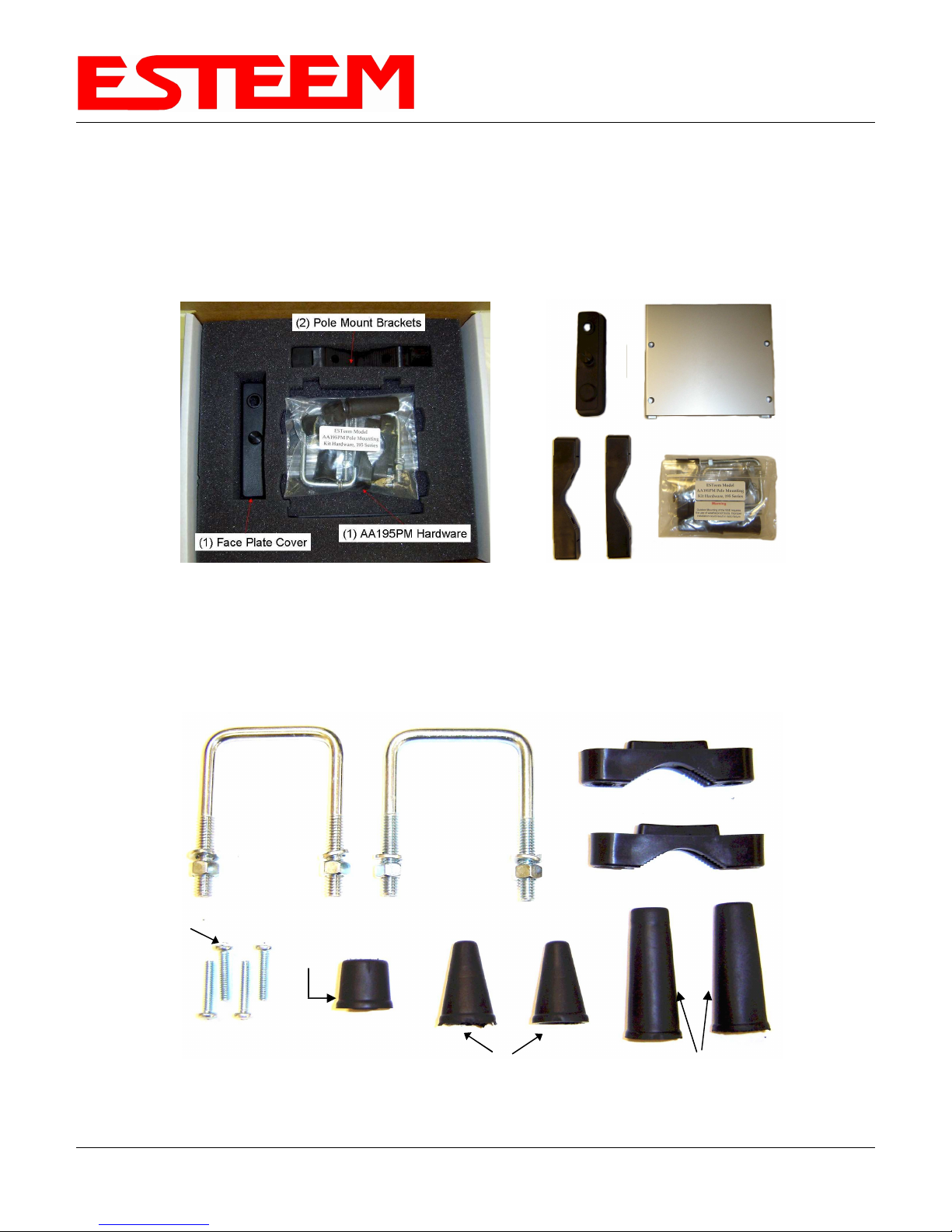
Figure 1: Packet Box Contents
1. If you purchased an AA195PM mounting kit with your Model 195E, the kit will be packed in the same packing box as the
ESTeem (Figure 1).
2. Remove and inventory the two (2) Pole Mounting Brackets, one (1) Two-Hole Face Plate Cover (with single port cover
installed), one (1) Heat Shield and (1) AA195PM Hardware bag from the packing box (Figure 1). Report any missing or
damaged items to ESTeem Customer Support (509-735-9092 Phone) as soon as possible for replacement.
(2) Square Bend U-Bolts with Hardware
(4) 10-24 Pan Screws
Revised: 11 Aug 08 8-3 EST P/N AA107D
(1) Weather Proof
Boot for Antenna
Port B (if not used)
(2) Ethernet
Cable Boot
(2) Pole Mount Clamps
(2) Direct Mount Antenna Boots for ESTeem
Approved Direct Mount Antenna Only
Figure 2: AA195PM Hardware Contents
Page 2
CHAPTER 8
ANTENNA SETUPS
3. Inventory the AA195PM Hardware bag for all the components listed in Figure 2.
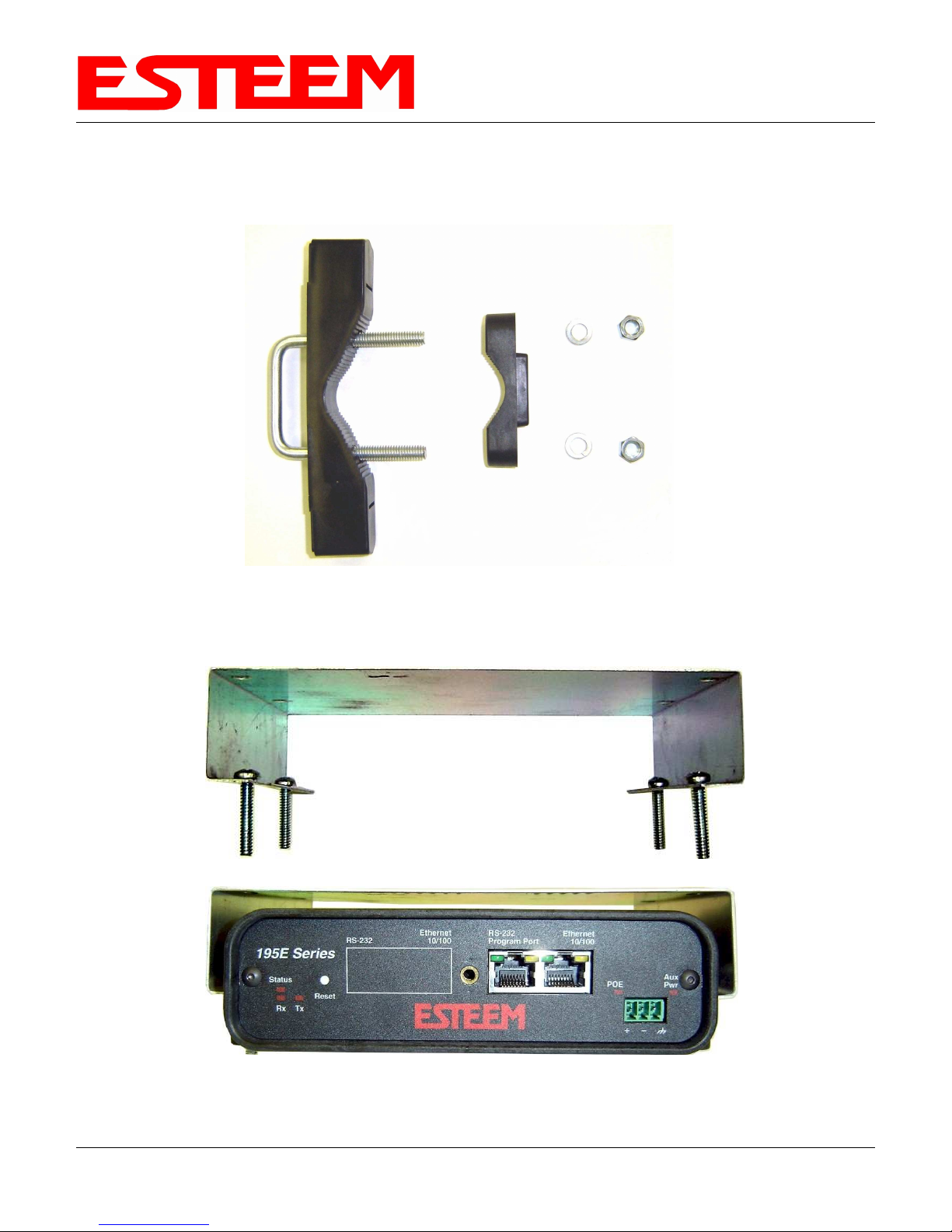
4. Assemble the two Pole Mounting Brackets with the included U-bolts, hardware and Pole Mount Clamps. Reference Figure 3.
Figure 3: Pole Mount Assembly
5. Place the four supplied 10-24 x 1” Phillips Pan Head screws through the mounting holes of the Heat Shield and attach to the to
the top of the ESTeem 195E (Figure 4).
Revised: 11 Aug 08 8-4 EST P/N AA107D
Figure 4: Heat Shield Attachment
Page 3

CHAPTER 8
ANTENNA SETUPS
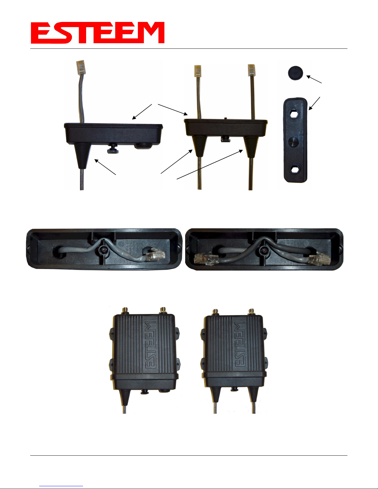
6. Attach the two Pole Mounting Brackets to the ESTeem Model 195E with the 10-24 x 1” Phillips Pan Head screws through the
Figure 5: Pole Mount Connection to Case
(Heat Shield Removed for Detail)
top of the heat shield. Reference Figure 5 (Heat Shield removed for detail).
7. Assemble the outdoor rated CAT-5e Ethernet cable (Not Provided) with the supplied Ethernet Cable Boot (Figure 6).
Ethernet Cable Boot
Figure 6: Ethernet Cable Assembly
8. Feed the CAT-5e Ethernet connector(s) through the Face Plate Cover and secure the Ethernet Cable Boot to the cover.
Reference Figure 7. NOTE: The Ethernet cable boot must be installed before the RJ-45 end is installed. If using the ESTeem
AA09.1 outdoor Ethernet cable, verify that the Ethernet cable boot end is routed toward the ESTeem 195E.
Revised: 11 Aug 08 8-5 EST P/N AA107D
Page 4
CHAPTER 8
ANTENNA SETUPS
Second Port Cover
Face Plate Cover
Ethernet Cable Boots
Figure 7: Ethernet Cable Routing
9. Route the CAT-5e Ethernet cable through the molded strain-relief fins in the Face Plate Cover (Figure 8) to secure the cable
and provide strain-relief for the connector. If a second Ethernet cable is installed, remove the second port cover and route
cable.
nd
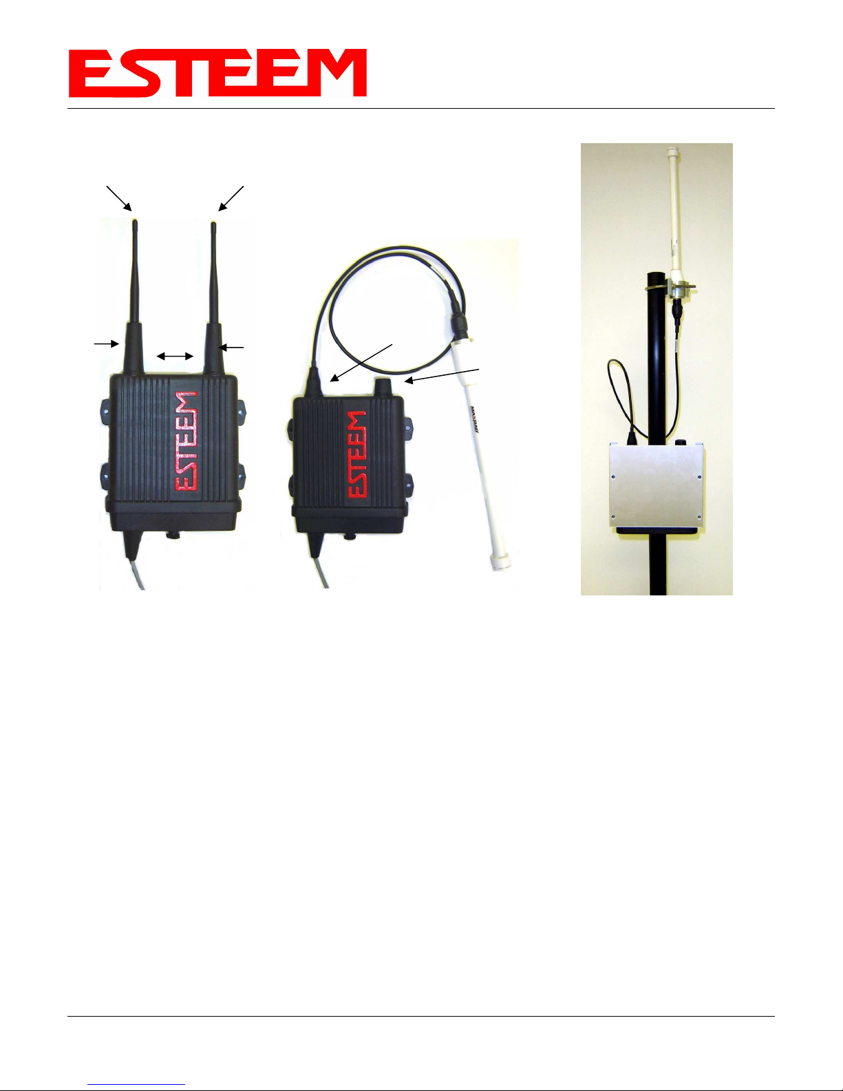
10. Plug the CAT-5e Ethernet cable to the Model 195E’s Ethernet port and secure the Face Plate Cover with the attached thumb
screw. Verify that the weatherproof seal on the Face Plate Cover is sealed against the outer rim of the Model 195E. Reference
Figure 9.
Figure 9: Face Plate Cover Installed on ESTeem
11. Attach the antenna connector boots as show in Figure 10 for either dual attached antennas or external antennas. You are now
ready to mount the ESTeem Model 195E
Figure 8: Face Plate Cover Strain Relief
Revised: 11 Aug 08 8-6 EST P/N AA107D
Page 5
CHAPTER 8
Port A
EST Approved Direct Mount
Antenna Only
Direct Mount
Antenna Boots
Port B
EST Approved External
Antenna With Factory
Installed Boot
ANTENNA SETUPS
Weather Proof Boot
NOTE: Remove Plastic
Connector Cover
Before Installation
Figure 10: Completed AA195PM Mounts
Face Towards The
South
(North America)
Caution: Outdoor mounting of the 195E requires the use of weatherproof boots. Improper installation
could result in radio failure.
Caution: Always mount the 195E vertically with the antenna ports on top.
Revised: 11 Aug 08 8-7 EST P/N AA107D
Page 6

CHAPTER 8
Brackets
50-60 Hz
232C
Weatherproof Boot
Pole Mounting
ANTENNA SETUPS
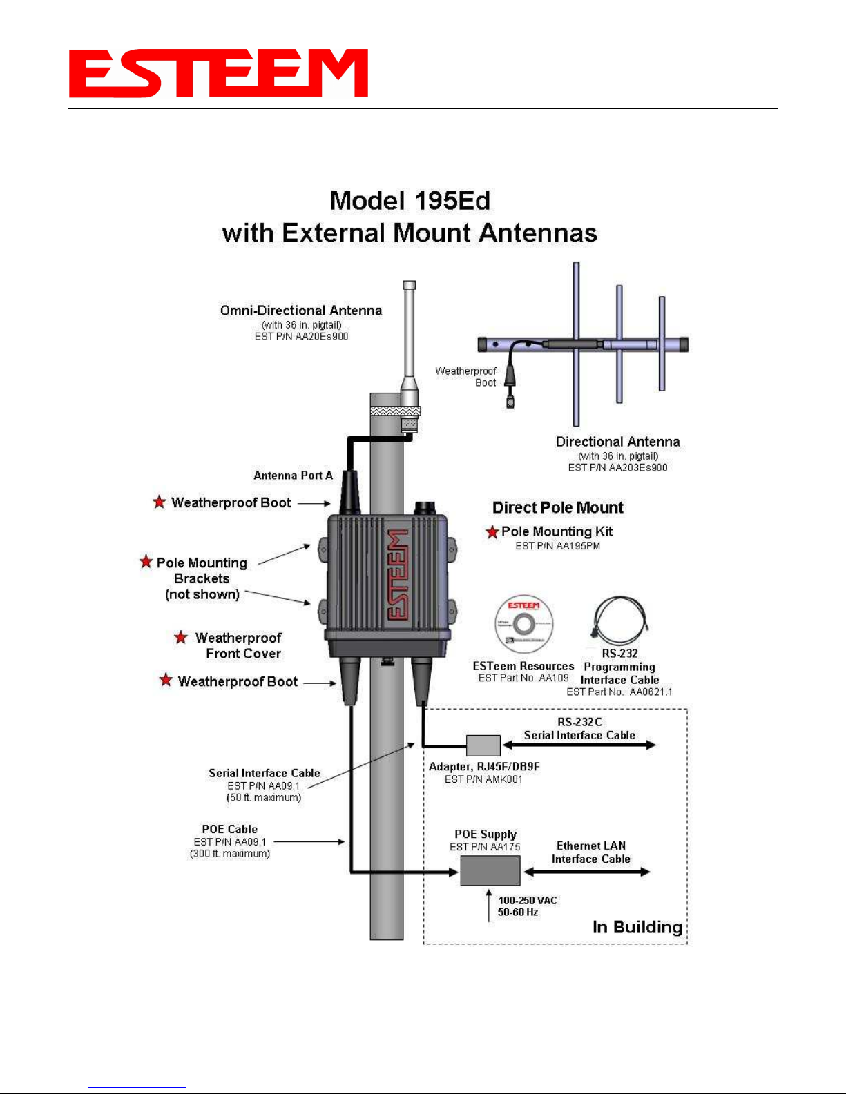
Model 195Ed with Direct Mount
Antenna and Surge Protection
Omni-Directional Antenna
EST P/N
AA20DMEs
Antenna Port A
Direct Pole Mount
Pole Mounting Kit
EST P/N
AA195PM
(not shown)
Weatherproof
Front Cover
Weatherproof Boot
Weatherproof Boot
Serial Interface Cable
EST P/N AA09.1 (50
ft. maximum)
POE Cable
EST P/N AA09.1
(300 ft. maximum)
ESTeem Resources
EST Part No. AA109
Ethernet Surge
Protection
EST P/N
RS-232
Programming
Interface Cable
EST Part No.
RS-
Serial Interface
Cable RS-232, RJ-45/DB9F
EST P/N AA0621.1
POE Supply
EST P/N
100-250 VAC
Ethernet LAN
Interface Cable
Caution: Always mount the 195Ed vertically with the antenna ports on top.
Revised: 11 Aug 08 8-8 EST P/N AA107D
Earth Ground
In Building
Page 7
CHAPTER 8
ANTENNA SETUPS
Caution: Always mount the 195Ed vertically with the antenna ports on top.
Revised: 11 Aug 08 8-9 EST P/N AA107D
Page 8

CHAPTER 8
ANTENNA SETUPS
Caution: Always mount the 195Ed vertically with the antenna ports on top.
Revised: 11 Aug 08 8-10 EST P/N AA107D
Page 9

CHAPTER 8
FRESNEL ZONE
ANTENNA SETUPS
The Fresnel zone shows the ellipsoid spread of the radio waves around the visual line-of-sight after they leave the antenna (see
figure above). This area must be clear of obstructions or the signal strength will be reduced due to signal blockage. Typically,
20% Fresnel Zone blockage introduces little signal loss to the link. Beyond 40% blockage, signal loss will become significant.
This calculation is based on a flat earth. It does not take into account the curvature of the earth. It is recommended for RF path
links greater than 7 miles to have a microwave path analysis done that takes the curvature of the earth and the topography of the
terrain into account.
Fresnel Zone Radius = 72.1 SQRT [(d1d2) / (F(d1 + d2)]
Units
Fresnel Zone Radius in feet.
d1 and d2 in statue miles
F in GHz
Revised: 11 Aug 08 8-11 EST P/N AA107D
Page 10

APPENDIX A
FCC-DOC INFORMATION
INFORMATION TO USERS
The ESTeem Model 195Ed complies with Part 15 of the
FCC Rules. Operation is subject to the following two
conditions: (1) This device may not cause harmful
interference, and (2) this device must accept any
interference received, including interference that may
cause undesired operation.
This Class A digital apparatus complies with Canadian
ICES-003. (Cet appareil numérique de la classe A est
conforme à la norme NMB-003 du Canada.)
Note to User:
Changes or modifications to this equipment not expressly
approved by Electronic Systems Technology for
compliance could void the user's authority to operate the
equipment.
The equipment has been tested and found to comply with the limits for a Class A digital device, pursuant to Part 15 of the FCC
Rules. These limits are designed to provide reasonable protection against harmful interference when the equipment is operated in a
commercial environment. This equipment generates, uses, and can radiate radio frequency energy and, if not installed and used in
accordance with the instruction manual, may cause harmful interference to radio communications. Operation of this equipment in a
residential area is likely to cause harmful interference in which case the user will be required to correct the interference at his own
expense.
Operation is subject to the following two conditions: (1) this device may not cause interference, and (2) this device must accept any
interference, including interference that may cause undesired operation of the device.
Other Information
Model 195Ed
Direct Sequence/OFDM Spread Spectrum Device
(USA) FCC ID: ENPESTEEM195ED
(Canada) IC No: 1457-195ED
Revised: 11 Aug 08 APX A-1 EST P/N AA107D
Page 11

APPENDIX A
FEDERAL COMMUNICATIONS COMMISSION FIELD OFFICES
ALASKA
1011 E. Tudor Rd.
Rm 240 Box 2955
Anchorage, AK 99510
CALIFORNIA
Interstate Office Park
4542 Ruffner St., Room 370
San Diego, CA 92111-2216
Los Angeles Office (LA)
Ceritos Corporate Tower
18000 Studebaker Rd., Room 660
Cerritos, CA 90701-3684
San Francisco Office (SF)
5653 Stoneridge Drive, Suite 105
Pleasanton, CA 94588-8543
COLORADO
Denver Office (DV)
215 S. Wadsworth Blvd., Suite 303
Lakewood, CO 80226-1544
FLORIDA
919 Federal Bldg
51 SE First Ave.
Miami, FL 33130
Tampa Office (TP)
2203 N. Lois Ave., Room 1215
Tampa, FL 33607-2356
GEORGIA
Atlanta Office (AT)
3575 Koger Blvd., Suite 320
Duluth, GA 30096-4958
HAWAII
7304 Prince Kuhi
Federal Building
Honolulu, HI
FCC-DOC INFORMATION
ILLINOIS
Chicago Office (CG)
Park Ridge Office Ctr., Room 306
1550 Northwest Highway
Park Ridge, IL 60068-1460
LOUISIANA
New Orleans Office (OR)
2424 Edenborn Ave. Suite 460
Metarie, LA 70001
MARYLAND
1017 Geo. Fallon
Building 31
Hopkins Plaza
Baltimore, MD
MASSACHUSETTS
Boston Office (BS)
1 Batterymarch Park
Quincy, MA 02169-7495
MICHIGAN
Detroit Office (DT)
24897 Hathaway Street
Farmington Hills, MI 48335-1552
MINNESOTA
691 Federal Building
316 N Robert St.
St. Paul, MN
MISSOURI
Kansas City Office (KC)
520 NE Colbern Road
Second Floor
Lee’s Summit, MO 64086
NEW YORK
1307 Federal Building
111 W. Huron
Buffalo, NY 14202
NEW YORK
New York Office (NY)
201 Varick Street, Suite 1151
New York, NY 10014-4870
OREGON
1782 Federal Building
1220 SW 3rd Avenue
Portland, OR 97204
PENNSYLVANIA
Philadelphia Office (PA)
One Oxford Valley Office Bld.
Room 404
2300 E. Lincoln Hwy
Langhorne, PA 19047-1859
PUERTO RICO
747 Federal Building
Carlo Chardon Ave.
Hato Rey, PR 00918
TEXAS
Dallas Office (DL)
9330 LBJ Freeway, Room 1170
Dallas, TX 75243-3429
5636 Federal Building
515 Rusk Avenue
Houston, TX 77002
WASHINGTON DC
Columbia Office (CF)
9300 East Hampton Drive
Capitol Heights, MD 20743
WASHINGTON
Seattle Office (ST)
11410 NE 122
Room 312
Kirkland, WA 98034-6927
nd
Way
Revised: 11 Aug 08 APX A-2 EST P/N AA107D
Page 12

APPENDIX B
SPECIFICATIONS
Model 195Ed Case Specifications
LED Indicators
Power On/Off Receiver On/Off
Carrier Detect On/Off Transmitter On/Off
Link Status On/Off
I/O Connectors
Ethernet 10/100Base T (Port 1) RJ-45 Female
Ethernet 10/100Base T (Port 2) RJ-45 Female
RS-232C Port
(2,400 to 115.2K baud)
RS-232C
Antenna Input/Output TNC Reverse Polarity Female
Remote Input Power Power Over Ethernet Cable
Direct Input Power Optional, Header Screw Connector
Programming Port (38.4 K baud) RJ-45 Female
Transmiter
Frequency of Operation
RF Data Rate
Tx Output Power 250 to 630 mW
RF Output Impedance 50 ohms
Receiver
RJ-45 Female
902 to 928 MHz
Software Selectable 11 Channels
1,2,5.5,6,9,11,12,18,24,36,48, & 54 Mbps Fixed or
Auto Scaling
DSSS/OFDM Modulation
Rx Sensitivity @ Frame Error Rate <10%
-72 dBm @54 Mbps to –95 dBm @ 1 Mbps
Frame Error Rate <10%
Power
Power over Ethernet
Power Connector on Unit 10 to 16 VDC
Receive 300 ma @ 12 VDC
Transmit 1100 ma @ 12 VDC
Case
Dimensions 1.9 in. H x 6.7 in. W x 6.2 in. L
Weight 1.25 lbs.
Outdoor Pole Mounting Kit Optional, EST P/N 195PM
Other
Warranty 1 Year
Temperature Range
Humidity 95% Non-condensing
FCC ID Number (USA) ENPESTEEM195ED
IC Number (Canada) 1457-195ED
Specifications Subject to Change Without Notice
IEEE 802.3af Standard Power Supply,
48 VDC @ 13 Watts
-30° to +60° C
Page 13

APPENDIX B
SPECIFICATIONS
Model 195Ed Case Specifications
Page 14

APPENDIX B
SPECIFICATIONS
Antenna Specifications
Model No: AA191s
Antenna Type: Omni-Directional, Permanent Vehicle Mount
Applications: Direct mount
Frequency: 896 to 940 MHz
Polarization: Vertical
Impedance: 50 ohms
Gain: 7 dBi (5 dBd)
VSWR: < 1.5 to 1
Front to Back Ratio: n/a
Horizontal Beamwidth: n/a
Vertical Beamwidth: n/a
Antenna Material: Molded Polymer
Mounting Hardware: Included
Antenna Connector: TNC-R Male
Antenna Envelope: 32 in. length
Weight: <1 lbs.
Model: AA20DMEs
Applications: Model 195Ed direct case mount
Antenna Type: Omni-Directional, Sleeve dipole
Frequency: 902 to 928 MHz
Polarization: Vertical
Impedance: 50 ohms
Gain: 2 dBi (0 dBd)
VSWR: < 2:1
Power: 10 W
Front To Back Ratio: n/a
Horizontal Beamwidth: n/a
Vertical Beamwidth: 60 degrees
Antenna Material: Polyurethane Plastic Radome
Recommended Mounting Hardware: n/a
Antenna Connector: TNC-R Male
Flexibility: +/- 20 °
Antenna Envelope: 8.8 in. length by .51 in. width
Temperature: -20 to +65 C°
Weight: 35 grams
Caution
Omni-directional antenna
should not be located within
23 cm of personnel.
Model 191Es
Caution
Omni-directional antenna
should not be located within
23 cm of personnel.
Model AA20DMEs
Revised: 11 Aug 08 APX B-3 EST P/N AA107D
Page 15

APPENDIX B
SPECIFICATIONS
Antenna Specifications
Model No: AA20Es900
Antenna Type: Omni Directional, DC Grounded
Applications: Fixed base
Frequency: 902 to 928 MHz
Polarization: Vertical
Impedance: 50 ohms
Gain: 7 dBi (5 dBd)
VSWR: 1.5:1 Typical
Front to Back Ratio: n/a
Horizontal Beamwidth: n/a
Vertical Beamwidth: 22 degrees @ ½ power
Antenna Material: Brass radiator, UV inhibited
fiberglass enclosed
Mounting Hardware: Base to Mast, Supplied.
Maximum Power Input:
Wind Survival: 100 mph
Bending Moment: 14.2 ft-lbs. @ 100 mph
Antenna Connector: TNC-R Male with 36in. pig-tail.
Antenna Envelope: 48 in. L x 1-5/16 in. Dia.
Weight: 1.75 lbs.
150 Watts
Caution
To comply with the FCC
exposure compliance
requirements, a separation
distance of at least 23 cm
must be maintained between
the antenna and all persons.
Model AA20Es900
Revised: 11 Aug 08 APX B-4 EST P/N AA107D
Page 16

APPENDIX B
SPECIFICATIONS
Antenna Specifications
Model No: AA203Es900
Antenna Type: Directional, DC grounded
Applications: Fixed base.
Frequency: 902 to 928 MHz
Polarization: Vertical or Horizontal
Impedance: 50 ohms
Gain: 7 dBi (5 dBd)
VSWR: < 1.5:1 Nominal
Front to Back Ratio: > 16 dB
Horizontal Beamwidth: 130 degrees @ ½ power
Vertical Beamwidth: 70 degrees @ ½ power
Antenna Material: Aluminum
Mounting Hardware: Heavy duty U bolts for mounting up to 2.0 in. pipe
(included).
Antenna Connector: TNC-R Male with 2 ft. pigtail with ESTeem
weatherproof boot.
Maximum Power Input: 50 Watts
Antenna Envelope: 1.1 ft. length by 6 in. width
Windload (RWV): 150 mph
Wind Surface Area: .11 ft²
Weight: 1 lbs.
Caution
To comply with the FCC
exposure compliance
requirements, a separation
distance of at least 23 cm
must be maintained between
the antenna and all persons.
Revised: 11 Aug 08 APX B-5 EST P/N AA107D
Model AA203Es900
Page 17

APPENDIX C
INTERFACE PORTS
ETHERNET INTERFACE
The ESTeem Model 195Ed’s Ethernet Port is a Full and Half-Duplex Auto-negotiation interface supporting both 10 Mbps and 100
Mbps (10/100BaseT). The Ethernet port is compliant with IEEE 802.3af Power Over Ethernet (PoE) to provide both data and
power over the same CAT-5E grade Ethernet cable. The port is compatible with TIA/EIA-568B cable configuration (Figure 1).
Figure 1: Ethernet Pin Layout
A second Ethernet port will be included if the serial option is added to the 195Ed. This second Ethernet port can be used in Bridge
Mode (HUB) or as a router.
Revised: 30 Jun 08 APX C-1 EST P/N AA107D
Page 18

APPENDIX C
INTERFACE PORTS
CONFIGURING DHCP SERVER
The ESTeem 195Ed Ethernet port supports both client and server Dynamic Host Configuration Protocol (DHCP). Figure 2 shows
the DHCP host configuration screen that will be shown if DHCP server is selected in the setup screens. Enter the values that match
the DHCP configuration for your network.
Revised: 30 Jun 08 APX C-2 EST P/N AA107D
Figure 2: DHCP Server Configuration
Page 19

RS-232C PROGRAMMING PORT
CONFIGURATION
The ESTeem Model 195Ed has a proprietary RS-232C
interface in a RJ-45 connector on the front panel. To
interface the 195Ed to the serial port on the computer,
you need ESTeem cable AA0621 that combines a
standard Ethernet patch cable to a 9-pin Female adapter.
The serial port on the ESTeem Model 192E can be used
to access the configuration menu in the ESTeem for
system and network configuration. The ESTeem
communications port operates at 38,400 bps, No Parity, 8
Data Bits and 1 Stop Bit (38,400,N,8,1). Configure your
terminal program to match these settings.
RS-232 PROGRAMMING PORT PIN-OUT TABLE
ESTeem Model AA0621
RS-232C Port Pin-Out Table
RJ-45
Pin No.
4
5
6
Function
Signal Ground (GND)
Receive Data (RxD)
Transmit Data (TxD)
DB-9
Pin No.
5
2
3
RS-232C DATA PORT CONFIGURATION
The ESTeem Model 195Ed has an RS-232C interface in a
RJ-45 connector on the front panel that can be installed as
an option . To interface the 195Ed to the serial port on the
computer, you need serial cable with the following pin-out:
ESTeem Model AA0621
RS-232C Port Pin-Out Table
RJ-45
Pin No.
1
2
3
4
5
6
7
8
Function
Data Set Ready (DSR)
Data Carrier Detect (DCD)
Data Terminal Ready (DTR)
Signal Ground (GND)
Receive Data (RxD)
Transmit Data (TxD)
Clear to Sent (CTS)
Request to Sent (RTS)
DB-9
Pin No.
6
1
4
5
2
3
8
7
APPENDIX C
INTERFACE PORTS
RS-232
Programming Port
Model 195Ed Serial Port Interface
Ethernet Pin-out
RS-232
Data Port
Model 195Ed Serial Data Port Interface
Revised: 30 Jun 08 APX C-3 EST P/N AA107D
Page 20

APPENDIX D
RADIO CONFIGURATION
195Ed FREQUENCY OF OPERATION
In a wireless Ethernet network all of the ESTeem Model 195Ed’s must be set to the same radio frequency of operation or channel.
Listed on the right is a table showing the channel and corresponding frequency of operation. The frequency of operation is
selectable when configuring the mode of operation of the 195Ed (reference Chapter 4). See Figure 1.
RF COMMUNICATIONS DATA RATE
Figure 1: RF Channel Selection
The RF data rate of the Model 195Ed can be programmed for operation at 1, 2, 5.5, 6, 9, 11, 12, 18, 24, 36, 48, or 54 Mbps. The
RF data rate can be set for a fixed rate or a specific range that is dynamically scaled by the Model 195Ed from monitoring the
received signal quality. The Model 195Ed can communicate with multiple client 195Ed devices at different data rates for each
device. By selecting all ranges from 1 to 54 Mbps you will be able to communicate with all client 195Ed regardless of their data
rate and signal quality requirements.
Dynamic scaling means that the Model 195Ed will operate at the highest RF data rate that is programmed into unit. If the received
data quality drops below the required minimums for reliable communications the Model 195Ed will reduce the data rate to the next
lowest step to increase signal quality. Conversely if the signal quality increases above the minimums the Model 195Ed will
increase the RF data rate the next highest level.
The ESTeem 195Ed is set at the factory to operate at maximized scaling speed data rates from 1-54 Mbps and should not need
adjustment. The RF Data Rate is programmed in the Model 195Ed through the Advanced Menu>Wireless LAN Settings>Wlan0
Device and the value for wlan0_OPRATES:. In the example shown in Figure 2 the RF Date Rate is programmed to dynamic scale
from 1 to 54 Mbps (recommend factory default setting). To set the values for the data rate, check the box next to the listed data rate
to enable this rate for operation.
Revised: 30 Jun 08 APX D-1 EST P/N AA107D
Page 21

APPENDIX D
RADIO CONFIGURATION
Figure 2: Advanced Data Rate Selection
RF BASIC RATE
The RF Basic Rate is the synchronization rate used to establish the initial connection between 802.11g and 802.11b communication
devices in Mbps. After the initial connection has been establish the RF communication rate will be determined by the RF
Communication Data Rate established above. Factory default is 1 through 11 Mbps shown in Figure 2 so that the unity will
establish communication with the older (slower) 802.11b devices. This lower rate also allows for a quicker reconnect when the
ESTeems are configured for EtherStation mode or working in a mobile environment.
The ESTeem 195Ed is set at the factory to operate at all speeds from 1-11 Mbps and should not need adjustment. The RF Basic
Rate is programmed in the Model 195Ed through the Advanced Menu>Wireless LAN Settings>Wlan0 Device and the value for
wlan0_AP_BASICRATES:. In the example shown in Figure 2 the RF Date Rate is programmed to dynamic scale from 1 to 11
Mbps (recommend factory default setting). To set the values for the data rate, check the box next to the data rate required.
Note: The Model 195Ed will only communicate with slower speed devices after synchronization if the RF Communication Data
shown above has been set to dynamically scale to 1 and 2 Mbps.
In general, do not set the RF Basic Rates above 11Mbps unless specifically instructed by ESTeem Customer Support.
Revised: 30 Jun 08 APX D-2 EST P/N AA107D
Page 22

APPENDIX E
SECURITY
OVERVIEW
The security for the ESTeem Model 195Ed, like all network security, must be multi-layered. One level of security is never enough
to make sure that data does not end up in the wrong hands. Please review the following security levels and decide what is the most
appropriate for your network.
128-BIT WEP
The 128 WEP uses a particular algorithm called RC4 encryption to encode and decode traffic that is based on a 104-bit encryption
key and a 24-bit Initialization Vector (IV). RC4 starts with a relatively short encryption key (104 bits) that is expanded into a
nearly infinite stream of keys to accompany the stream of packets.
The basic concept of RC4 is good, but the way it’s implemented in WEP leaves it open to compromise. The researchers that test
the integrity of the system usually focus on one piece of the implementation, the Initialization Vector (IV).
The IV (24 bits) is the algorithm component that’s supposed to keep expanded keys from repeating. From the researcher’s point of
view, a high-volume access point is mathematically guaranteed to reuse the same key stream at least once a day. When this
happens, it’s called an IV collision this becomes a soft spot to enter the system.
The researchers aren’t saying that it’s easy to break into the system, or that it’s being done on a regular basis, only that it is possible
and that administrators should consider ways to reduce the possibility.
WPA
Wi-Fi Protected Access with Preshared Key (WPA PSK)
WPA, which uses 802.1x, was introduced in 2003 to improve on the authentication and encryption features of WEP. All
authentication is handled within this access point device. WPA has two significant advantages over WEP:
1. An encryption key differing in every packet. The TKIP (Temporal Key Integrity Protocol) mechanism shares a starting
key between devices. Each device then changes their encryption key for every packet. It is extremely difficult for hackers
to read messages even if they have intercepted the data.
2. Certificate Authentication (CA) can be used, blocking a hacker posing as a valid user.
Wi-Fi Protected Access with Enterprise Server (WPA Enterprise)
Like WPA PSK, WPA Enterprise uses 802.1x. However, a backend authentication server handles the authentication decision. The
most commonly type of authentication server is a RADIUS server. The ESTeem Model 195Ed can be configured to operate with
an established RADIUS server on the network.
WPA is server/client relationship from a software driver on a computer’s wireless LAN (WLAN) card to an Access Point. The
scope of WPA is limited in use to this configuration only. The ESTeem Model 195Ed can support WPA Enterprise and PSK as an
Access Point, but the level of security on the Bridging layer is configured separately.
ACCESS CONTROL LIST (ACL)
The ACL is one of the simplest yet most secure methods of network security. The ACL is a configurable MAC filter in the Model
192E that can be set to allow specific MAC address on the wireless network by individual address or address ranges. The same
filter can also be set to reject individual MAC addresses or address ranges.
The MAC address is a unique, 6 hexadecimal field address assigned at the manufacturer that can not be changed. The MAC
address is traceable through the IEEE governing body to the manufacturer and is the “fingerprint” for all Ethernet devices.
Revised: 30 Jun 08 APX E-1 EST P/N AA107D
Page 23

APPENDIX E
SECURITY
Using a combination of both the WPA or 128-Bit WEP encryption and the ACL filter provide the ESTeem an extremely secure
wireless networking layer.
DISABLING BROADCAST PROBES AND HIDING SSID
A simple but very effective way of securing a network is to make the network difficult to find. By disabling broadcast probes and
hiding the Service Set Identification (SSID), wireless and network “sniffers” will not be able to find your ESTeem Model 195Ed
network. To gain access to the wireless network, you would be required to have the SSID and all security loaded in the WLAN
card software prior to entering the network.
MASQUERADE MODES
When the ESTeem Model 195Ed is configured in either the Access Point Masquerade or the Client Masquerade modes, the
wireless modem functions as a network firewall. If access to the wired network is the greatest concern, place the ESTeem in the
Masquerade mode and the wireless network will be completely isolated from the wired Ethernet network.
INCREASING NETWORK SECURITY
The following are a few suggestions to help improve the overall security of your wireless network:
1. Enable the security. If you research all of the articles regarding hackers, they have gotten into the user’s network due to the
security not being enabled.
2. Set the ACL filter to include only those MAC address of the wireless Ethernet device being used on the network.
3. Set "Hide SSID" to True. As you take your access point out of the box, broadcast SSID is enabled which means that it will
accept any SSID. By hiding the SSID configured in the client must match the SSID of the access point.
4. Make sure the keys are not reused in your company, since reuse increases the statistical likelihood that someone can figure the
key out and change the default password on your access point or wireless router
5. Change the default SSID of your product. Don't change the SSID to reflect your company's main names, divisions, or products.
It just makes you too easy to target.
6. As a network administrator, you should periodically survey your company using a tool like NetStumbler to see if any "rogue"
access points pop up within your company without authorization. All of your hard work to "harden" your wireless network
could be wasted if a rogue AP was plugged into your network behind the firewall.
7. Many access points allow you to control access based on the MAC address of the NIC attempting to associate with it. If the
MAC address of your NIC isn't in the table of the access point, you won't associate with it. And while it's true that there are
ways of spoofing a MAC address that's been sniffed out of the air, it takes an additional level of sophistication to spoof a MAC
address. The downside of deploying MAC address tables is that if you have a lot of access points, maintaining the tables in
each access point could be time consuming. Some higher-end, enterprise-level access points have mechanisms for updating
these tables across multiple access points of the same brand.
8. If you're deploying a wireless router, think about assigning static IP addresses for your wireless NICs and turn off Dynamic
Host Configuration Protocol (DHCP). If you're using a wireless router and have decided to turn off DHCP, also consider
changing the IP subnet. Many wireless routers default to the 192.168.1.0 network and use 192.168.1.1 as the default router.
9. A simple security technique used by the military is to have the administrator periodically change the key for the system i.e.
weekly, monthly, etc.
Revised: 30 Jun 08 APX E-2 EST P/N AA107D
Page 24

APPENDIX F
TROUBLESHOOTING
TESTING COMMUNICATION LINK
After you have configured at least two of the Model 195Ed wireless Ethernet modems for operation, you can verify communication
with each the following steps:
Status Light
The quickest source of link status is to view the Status Light
on the face of the 195Ed (Figure 1). If the Status light is solid
on any other 195Ed except the Timing Master, the Model
195Ed has a connection to another Model 195Ed listed in the
Peer Table. On the Timing Master the status light will be
illuminated at all times.
Status Screen/Peer Table
To view detailed information on the status of the communication link (such as connection speed, signal strength and last update
time) you can open the Status Screen from the Web Interface. After press the Status tab at the top of the screen the Status:
Summary will be displayed showing the status of all ports and memory in the 195Ed (Figure 2).
Status LED
Solid Red on Link
Figure 1: Connection Status Light
Revised: 30 Jun 08 APX F-1 EST P/N AA107D
Figure 2: Peer Summary Table
Page 25

APPENDIX F
TROUBLESHOOTING
Under the Wireless Status heading click on the View Peer Table and the Peer Table Screen will be displayed (Figure 3).
Opposite Modem’s Wireless MAC
Receive Signal Strength (dBm)
Last Packet Received
Peer Modem ID
Other Access Points
Figure 3: Repeater Peer Table
Repeater Peers - The Peer Table will display all connected 195Ed configured to repeat to this ESTeem by their Wireless (WLAN)
MAC address.
Received Signal Strength – This is the first of the two numbers listed in the block. This signal strength value is listed in dBm.
Last RX – This is the time of the last received data packet. When monitoring the status menu, it is important to note the time the
last transmission was updated so you are not looking at “stale” data.
Current Data Rate – This is the current speed the last data packet received by the Model 195Ed. Note that the speed is listed in
kbps.
Modem ID – This is Modem ID for the opposite repeater peer.
Revised: 30 Jun 08 APX F-2 EST P/N AA107D
Page 26

APPENDIX F
TROUBLESHOOTING
Peer Table Details
To further analyze a repeater peer link, press the hyperlink for any WLAN MAC address listed in the repeater peer summary
(Figure 3) and the Peer Info screen will be displayed (Figure 4). Detailed information on the Counter, Statistics, Link Encryption,
Beacon and Probes can found by selecting the respective hyperlink.
Figure 4: Repeater Peer Table
TROUBLESHOOTING TIPS
General (Applicable to All Modes of Operation)
Where do I find the latest firmware version number? – We have the latest version number of the Model 195Ed firmware listed on
the ESTeem Web site (www.esteem.com) under the Model 195Ed product page.
How and when do I update the Model 195Ed firmware? - You should only update the Model 195Ed firmware if you are having a
specific problem and it is recommended that you do so by ESTeem Customer Support personnel. All the update instructions and
files are located on the ESTeem FTP site at the following address:
ftp://www.esteem.com/195Ed
Do all firmware versions have to be the same to communicate between the Model 195Ed? – It is not necessary for all the firmware
versions to be the same revision to communication, but the later version may have added features that the other versions will not
recognize.
What characters are valid for WEP Key entry? - Only the Hexadecimal characters 0-9 and A-F are valid for key entry.
What ESTeem Utility version is required to program the Model 195Ed? – The ESTeem Utility program is not required to program
the Model 195Ed. The 195Ed can be programmed using any Terminal Emulation program (such as Windows HyperTerminal) and
any web browser program.
Revised: 30 Jun 08 APX F-3 EST P/N AA107D
Page 27

APPENDIX F
TROUBLESHOOTING
What is the speed and duplex configuration on the Model 195Ed – The Model 195Ed is an auto-negotiation full/half-duplex 10/100
Base-T interface. Ether a cross-over or patch cable is supported.
Access Point Repeater Mode
If I am unable to communicate with any of the remote sites, what is the most common cause? - The most common cause a
communication problems with the 195Ed is that the SSID was entered incorrectly for the radio network. The 195Ed uses the SSID
to set the frequency hopping pattern and it must be the same on all modems.
How long does it take to re-establish the Wireless Ethernet Network? - If a communication link is lost and the Wireless Network
needs to re-establish the repeater routes, the time can take up to 30 seconds.
Should the AP Repeater Mode be used on mobile equipment? - The AP Repeater mode should be used on equipment that will not
change the Repeater Route as it moves. For example, if a mobile device such as a crane can communicate directly to another
ESTeem and will not loose the link in its travel, the AP Repeater Mode could be used. If the device requires two ESTeem Model
195Ed’s (Base and Repeater) to maintain communication across its complete travel, the Station Modes should be used on the
mobile device. The problem will be in the time that the mobile ESTeem will take to transfer between the two sites. In Access Point
Repeater mode the transfer can take up to 30 seconds, while the EtherStation mode will transfer without a packet loss.
Does WEP have to be used? – The WEP does not have to be enabled for the modems to communicate, but all modems must be
configured the same way.
Correct configuration, but cannot establish communications. – In addition to the network configuration, all 195Ed modems
configured in the AP mode must share the same SSID and be on the same frequency channel. The most likely cause of the error is
the WLAN MAC address is not configured in both 195Ed’s repeater tables. If only one side is configured, everything will appear
to be correct but no communication will function.
EtherStation
How do I access the Model 195Ed web page in EtherStation Mode? The Model 195Ed does not have an active web browser when
configured in EtherStation mode. You must access the ESTeem with the ESTeem Discovery Program or through the RS-232 port
after configuration in this mode. To monitor the link status, you can use the EtherStation Status program.
What IP address do I configure the ESTeem in EtherStation mode? – The Model 192E will not have an IP address in EtherStation
mode.
I can not link my device into the wireless network – Verify that the MAC address of the device is exactly the same as configured in
the Model 195Ed. The MAC address must have colons between the values.
Can I connect my Model 195Ed in EtherStation mode to a HUB or Ethernet Switch? – No. The modem must be connected directly
to the Ethernet device for which it is programmed. In EtherStation mode the Model 195Ed can only service ONE Ethernet device.
Revised: 30 Jun 08 APX F-4 EST P/N AA107D
Page 28

APPENDIX G
UTILITIES & FEATURES
ESTEEM DISCOVERY UTILITY
The ESTeem Discovery Utility will allow you to
configure the IP address on the Model 195Ed to match
your network regardless of its current IP subnet. This
utility will also allow you to update the software in the
195Ed and open the web configuration for that wireless
modem.
Installation
To install the Discovery Utility on your computer,
inserting the Resource Disk in your CD drive.
Note: The ESTeem Resource Disk is stand-alone copy of
the ESTeem Web site (Figure 1). Navigation of the
Resource Disk is as simple as using your web browser. All technical documentation, User’s Manuals and the ESTeem Utility
Program is available on the disk.
1. Place the ESTeem Utility CD in your CD-ROM drive. The CD will auto load the ESTeem main page
Note: If the page does not auto load, open your web browser and set your address line to D:\index.html (Where D: is the
drive letter for your CD-ROM drive).
2. From the Main Page select ESTeem Utilities and click on ESTeem Discovery Utility (Figure 2).
Note: This program is saved in a compressed file format. Microsoft Windows XP® will open the file directly, but other
operating systems will require a common compression program such as WinZip available for download at
http://www.winzip.com
Figure 1: ESTeem Resource Main Page
Revised: 30 Jun 08 APX G-1 EST P/N AA107D
Figure 2: Discovery Utility Download
Page 29

APPENDIX G
UTILITIES & FEATURES
3. Double click on the 195EdiscoverySetup.exe file listed in the window to install the program.
4. Connect the Model 195Ed to your computer either direct to the Ethernet card or through a HUB/Switch using a CAT-5e
Ethernet cable. The Ethernet port on the 195Ed supports Auto-Negotiation so either a patch cable or crossover cable will
work. Open the ESTeem Discovery Program and press the Discover Modems button. The Model 195Ed will be displayed in
the program by the Ethernet MAC address and Current IP Address (Figure 3).
Figure 3: Discovery Program Main Page
Note: The SSID, Mode of Operation and Modem ID will be adjusted through the web configuration manager..
5. Double-click on the 195Ed you want to program and the Configure IP Address window will be displayed (Figure 4). Enter an
IP address and Subnet Mask for the 195Ed that matches your network subnet and press the OK button to save this to the
ESTeem. You will receive notification that the Configuration was Successful and the 195Ed will reboot. Proceed to ESTeem
Setup in Chapter 4.
Revised: 30 Jun 08 APX G-2 EST P/N AA107D
Figure 4: Change IP Address Window
Page 30

APPENDIX G
UTILITIES & FEATURES
Firmware Updates
To update firmware on any ESTeem Model 195 that is shown on the Discovery program, “right-mouse” click on the 195’s MAC
address and select Update from the menu (Figure 5). Once you locate the update file, select the Open button and the 195 will
update, validate and then reboot with the updated operating system.
Figure 5: Discovery Features Menu
Opening Web Browser
To quickly open a web browser page to the IP address programmed in the 195 modem, “right-mouse” click on the 195’s MAC
address and select Open Browser from the menu (Figure 5). If your computer is configured for the same IP subnet at the ESTeem
195 wireless modem, you will be asked to sign in with the Username and Password (Figure 6) and you can begin programming the
Model 195 for your application.
Revised: 30 Jun 08 APX G-3 EST P/N AA107D
Figure 6: ESTeem Web Page Log-on Screen
Page 31

APPENDIX G
UTILITIES & FEATURES
ETHERSTATION STATUS PROGRAM
When configured for EtherStation mode, the Web Configuration Manger is turned off. To gather information from the 195Ed on
Access Point, link status and received signal strength you will need to install the ESTeem 195E Status Utility. The EtherStation
Status Utility version 2.0.0.0 or greater provides a new feature where it will automatically program the connected ESTeem 195Ed
to match up with the computer running the software. This software requires that the ESTeem 195Ed has software version
302.8.102 or greater installed for this feature to function.
This software program is found on the AA109 Resources Disk or available from the ESTeem web site. To install the utility, please
complete the following:
Installation
The ESTeem Discovery Utility will allow you to configure the IP address on the Model 195Ed to match your network. Install the
Discovery Utility on your computer by inserting the Resource Disk in your CD drive.
Note: The ESTeem Resource Disk is stand-alone copy of the ESTeem Web site (Figure 1). Navigation of the Resource Disk is as
simple as using your web browser. All technical documentation, User’s Manuals and the ESTeem Utility Program is available on
the disk.
1. Place the ESTeem Utility CD in your CD-ROM drive. The CD will auto load the ESTeem main page
Note: If the page does not auto load, open your web browser and set your address line to D:\index.html (Where D: is the
drive letter for your CD-ROM drive).
2. From the Main Page select ESTeem Utilities and click on EtherStation Status Utility
Note: This program is saved in a compressed file format. Microsoft Windows XP® will open the file directly, but other
operating systems will require a common compression program such as WinZip available for download at
http://www.winzip.com
3. Double click on the 195EStatusSetup.exe file listed in the window to install the program.
4. Connect the Model 195Ed to your computer either direct
to the Ethernet card or through a HUB/Switch using a
CAT-5e Ethernet cable. The Ethernet port on the 195Ed
supports Auto-Negotiation so either a patch cable or
crossover cable will work. Open the ESTeem Status
Program and a status icons will appear in your system tray
(Figure 9). When the status menu is opened from the
system tray, the status window will be displayed (Figure 7)
to show the Access Point MAC address and signal
strength. The tray icon and Signal Strength bar will
display the colors from Green, Yellow to Red on
progressively poorer signal or will show Grey if roaming.
Note: This Utility will only operate with an ESTeem Model 195Ed in EtherStation mode.
Figure 7: EtherStation Status Program
Revised: 30 Jun 08 APX G-4 EST P/N AA107D
Page 32

APPENDIX G
UTILITIES & FEATURES
SETTING LOCAL TIME
The ESTeem Model 195Ed will be shipped from the factory with the internal real-time clock set to Pacific Time. To change the
clock settings to the local time for accurate log file entries:
1. Select Advanced from the top Menu then Wireless LAN Settings>wlan0 device and press the Next button (Figure 8).
2. Select Global Settings>Set System Time from the menu and press the Next button to continue.
Figure 8: Advanced Features Screen
3. Select the correct date and time from the drop-down menus (Figure 9) and press the Set System Time button to save the
time to the real time clock.
Figure 9: Advanced Features Screen
Revised: 30 Jun 08 APX G-5 EST P/N AA107D
Page 33

APPENDIX G
UTILITIES & FEATURES
CONFIGURING TIME SERVER
Enabling NTP time synchronization services on the ESTeem 195Ed will allow to use time services from upstream services to keep
the time on the system accurate.
To allow time synchronization, the Model 195Ed must be configured with the NTP Daemon enabled and the appropriate IP address
of the upstream network NTP server.
1. Select Advanced from the menu items and Global Variables (Figure 10).
Revised: 30 Jun 08 APX G-6 EST P/N AA107D
Figure 10: Advanced Settings Menu
Page 34

APPENDIX G
UTILITIES & FEATURES
2. Press the next button and Figure 11 will be displayed. At the bottom of the page are the NTP server configurations.
3. The NTP daemon is enabled by selecting YES for NTP ENABLE (Figure 11). When enabled, the NTP daemon will use
time services from upstream services to keep the time on this system accurate.
Figure 11: NTP Settings
4. Next, the NTP SERVICE ENABLE should be configured to “YES,” if you want to allow the system to provide NTP
service for clients wishing time synchronization (Figure 11).
5. The final step in configuring NTP services is to enter the IP address or the host name of the upstream NTP server.
Revised: 30 Jun 08 APX G-7 EST P/N AA107D
Page 35

APPENDIX G
6. Once configuration is complete, press the “Return to Advanced” button.
UTILITIES & FEATURES
Figure 12: Advanced Settings Menu
7. To complete the configuration, select “Commit and Reboot.” The ESTeem 195Ed will now commit the configuration
changes and reboot. (Figure 12)
Revised: 30 Jun 08 APX G-8 EST P/N AA107D
 Loading...