


ESTEAM CLEANING SYSTEMS
OWNER’S MANUAL
Congratulations on your selection of a new E1700 Series soil extractor
built in Canada by “Esteam Cleaning Systems.” Our goal has been to
produce the best high performance line of carpet cleaning equipment on the
market today. Reading your owners manual will help to achieve maximum
benefit from your purchase.

2
TABLE OF CONTENTS
Page No.
Introduction on the E1700 Series 3
Specifications 3
Maintenance 4
Safety Inf ormation 5
Operating Instructions 6
Trouble Shooting 9
Schematic Diagram 13
Warranty Registration 29
Warranty 30

3
INTRODUCTION
E1715
E1715-20
E1715-05
E1715-20-05
E1715-10
E1715-20-10
Volts
115 volts (220volts)
115 volts (220 volts)
115 volts (220 volts)
Vacuum lift
150”
185”
150”
PUMP
150 psi
150 psi
150 psi
HEATER
(Clean water)
(55.2litres)
LENGHT
25.5 inches (65 cm)
25.5 inches (65 cm)
25.5 inches (65 cm)
WIDTH
17.5 inches (45 cm)
17.5 inches (45 cm)
17.5 inches (45 cm)
HEIGHT
37 inches (94 cm)
37 inches (94 cm)
37 inches (94 cm)
WEIGHT
102 lbs (46 kgs)
107 lbs (48.5 kgs)
112 lbs (50.5 kgs)
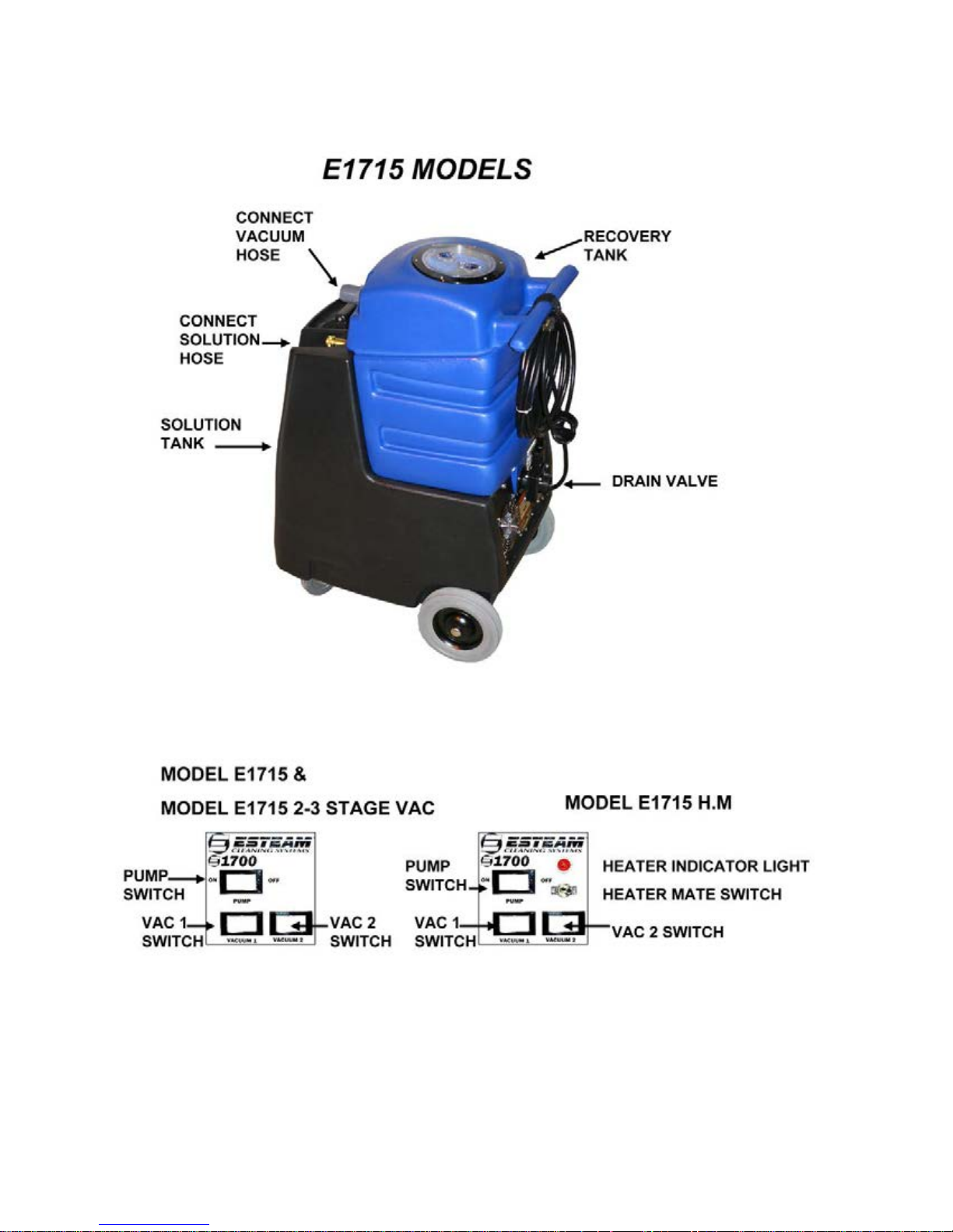
Be it a small residential job or a large commercial contract, Esteam industrial carpet cleaning extractors are
right for your needs. The E1715 is an economical, compact, portable soil extractor with the power and
capabilities required by professional cleaning technicians.
Only the highest quality components go into our equipment, to deliver you strength and reliability in a long
life, high performance machine. The E1715 ’s housing is made of high impact, unbreakable polyethylene.
We are so confident in the housing that we put a lifetime guarantee on it.
The E1715 incorporate a unique dual vacuum system. Two vacuum motors hooked up in sequence
produce 150” of water lift and 185” of water lift with optional 2-3 stage. To compliment the vacuum lift the
E1715 comes with a 150 PSI Diaphragm pump. The E1715 comes complete with an optional 200
0
F
internal heater.
The E1715 ’s clean water solution tank has a 17 gallon capacity and the dirty water recovery tank has a
14.5 gallon capacity. Built into the recovery tank the E1715 comes standard with high water automatic shut
off. You never have to fear overfilling your recovery tank as the vacuums will automatically stop extracting
when the recovery tank becomes full.
SPECIFICATIONS
E1715
ELECTRICAL
Amps
VACUUM MOTOR
Cfm’s
INTERNAL
SOLUTION TANK
RECOVERY TANK
One cord
15 amps
2-2 stage
94
N/A
17 gallons (64.5
litres)
14.5 gallons
Two cords
15 amps per cord
2-3 stage High
Performance
101
N/A
17 gallons (64.5 litres)
14.5 gallons (55.2 litres) 14.5 gallons (55.2 litres)
Two cords
15 amps per cord
2-2 stage
94
1850 watt / 200ºF
17 gallons (64.5 litres)

4
MAINTENANCE
1. After each job, disconnect the vacuum hose and run the vacuums for 3 to 5
minutes to eliminate moisture build up in the components. This prolongs vacuum
life and reduces the servicing the vacuums will require. If excess water enters the
vacuums due to failure of the float ball sh ut-off system, run the vacuums for at
least 15 minutes, and spray a small amount of penetrating oil (i.e. WD-40) directly
into the vacuum inlet inside the recovery tank. This will help displace any
remaining moisture and prevent corrosion of the vacuum components.
2. At the end of each day run clear water through the pump. Wipe out the solution
tank using a clean cloth. Check the acorn screen filter for damage, and replace it if
it becomes clogged, corroded or crushed. Never store tools or hoses inside the
tanks of the machine, as damage t o the com pon ent s may occur.
3. Rinse out the recovery tank with clean water and clean the float cage screen
assembly. This will eliminate odor problems inside the tank, as well as preventing
damage to the vacuum system caused by faulty float operation.
4. Check that the recovery tank float ball is free of debris and operating properly. The
float cage may be unscrewed from the mounting pipe for complete cleaning. Be
sure to reassemble the float assembly properly.
5. To keep your E1715 extractor looking new, wipe the polyethylene housing with
vinyl cleaner or protector as needed.
Always unplug power cord/s before opening access panel.
WARNING: Do not allow the machine to freeze. System damage from freezing can
take place in as little as 5 minutes in sub-zero conditions. This will cause lines with
water in them to crack and break. Heaters and pumps with water in them subject to
freezing will also crack and break. Allowing the machine to freeze with water in the
system and/or using improper chemicals will void the warranty.

5
SAFETY INFORMATION
1. Prior to inspection or repair of this machine, disconnect all electrical cords
rendering the machine powerless. Failure to do so could result in serious or fatal
injury.
2. Inspect unit daily for worn or damaged components. E.g. frayed cord, loose plug,
or a plug with missing ground pin, etc.
3. This unit should only be operated when in an upright position on a level surface.
4. Do not operate unit unless it is properly grounded in a 3 pin grounded outlet.
Never bend or remove ground pin from plug.
5. Ensure filters and screens are free from lint of dirt.
6. Do not run unit if vacuum motors or pump are wet. Allow sufficient time for motors
to dry before plugging unit in.
7. Do not use solvent based cleaning products in this extractor.
8. Keep air inlets and exhaust ports free from obstructions. Blocked air inlets or
exhaust ports can cause the unit to over heat.
9. Do not use solution or recovery tanks for storing hoses, cords or accessories.
10. When using electrical equipment around water it is important to wear rubber soled
shoes and keep machine properly grounded at all times. Failure to do so could
result in a fatal electric shock.

6
OPERATING INSTRUCTIONS
1. Plug in the machine. Always check to ensure the plug has the ground prong
attached to prevent injury due to electric shock. Never remove the ground prong
from the plug.
2. We recommend the use of a liquid defoamer, to prevent the machine from
prematurely shutting off due to excess foam in the recovery tank. Turn on vacuum
and pour approximately ¼ cup of Esteam Liquid Defoamer into the end of the
vacuum hose.
NOTE: If the unit is equipped with a heater, two power cords are supplied. The
machine will need to be plugged into two different circuits to handle the combined
amperes. Your solution will be heated to approximately 2000F.
3. 150 PSI pump priming instructi ons : USING OPTIONAL PRIME HOSE
- Fill fresh water tank
- Attach prime hose to quick connect on machine
- Place the other end of prime hose into vacuum port and hold
- turn vacuum and pump switches on
- Once a continuous flow of water is being drain through the prime hose, this
indicates pump is primed
- Turn off vacuum and pump switches and disconnect prime hose
- Connect solution hose and v ac hos e to mac hi ne
- Turn vacuum and pump switches on
- Machine is ready to use.
TO USE YOUR E1715 OPTIONAL HEATER:
A) Hook the wand solution hose to the quick connect of your machine.
B) Plug the heater power cord into a wall outlet that is on a separate circuit from the
other cord.
C) Turn the heater switch on.
D) When the red light goes out, solution is heated and ready to use.
WARNING: If your heater does not work DO NOT attempt to repair it yourself, call
your distributor for repair procedures. Using solvents in heaters can be hazardous
and will void your warranty. Allowing heaters to freeze will crack the heater cartridge
and will also void your warranty.
DANGER: No solvents of any type may be used in this system at any time. The use
of solvents is extremely hazardous resulting in possible fire and/or explosion.

7
OPERATING INSTRUCTIONS (CO NTINUED)
4. Connect the vacuum and solution hoses to the carpet cleaning wand.
5. Proceed to clean the carpets.
6. 6When the recovery tank becomes full, vacuum will automatically stop extracting.
When the vacuum stops extracting it will make a distinctive high pitched noise as
all air flow will be cut off. At this time switch the unit off. To empty the recovery
tank use the black 450 elbow provided to direct waste water into a 20L bucket or
toilet.
7. NOTE: Ensure that the automatic high water shut off screen inside the recovery
tank is free from any obstructions. Be sure to close drain valve before resuming
cleaning.
8. To empty the solution tank remove vacuum hose from wand. Turn on vacuum and
extract solution from solution tank into recovery tank, then drain recovery tank.
9. NOTE: Do not completely submerge the end of the vacuum hose into the solution.
Allow some air to enter the end of the vacuum hose with the liquid.
10. When the job is completed, empty and rinse out the solution and recovery tanks.
Allow vacuum to run 3 to 5 minutes. This will eliminate all moisture from vacuum
assuring long vacuum lift.
11. WARNING: When using electrical equipment around water it is important to wear
rubber soled shoes and keep machine properly grounded at all times. Failure to
do so could result in a fatal electric shock.
8

9
TROUBLESHOOTING
WARNING: Prior to inspection or repair of this machine, disconnect all electrical
cords rendering the machine powerless. Failure to do so could result in serious or
fatal injury.
PROBLEM CAUSE SOLUTION
1. Entire unit will not 1. Unit not plugged in 1. Connect unit to 3
operate prong outlet
2, Blown fuse or breaker 2. Check fuse panel
for plug in outlet for blown fuse
3. Loose wiring 3. See dealer
2. Pump will not run 1. Switch not turned on 1. Turn on switch
2. Kink in solution hos e 2. Remove kink
3. Plugged jet or quick 3. Remove blockage
connect
4. Broken switch 4. See dealer
5. Loose wiring 5. See dealer
6. Pump defective 6. See dealer
3. Vacuums will not 1. Switch not turned on 1. Turn on switch
run
2. Broken switch 2. See dealer
3. Loose wiring 3. See dealer
4. Blocked rotor 4. See dealer

10
TROUBLE SHOOTING (CONTI NUE D)
PROBLEM CAUSE SOLUTION
4. Pump runs but 1. Out of solution 1. Fill with solution
does not pump
solution 2. Pump inlet screen 2. Clean inlet screen
plugged
3. Pump air locked 3. Press trigger to open
valve on cleaning wand
to relieve air
4. Internal or external 4. See dealer
solution line damaged
and leaking
5. Pump runs but has 1. Partial kink in solution 1. Remove kink
loss of pressure hose
2. Jet orifice opening on 2. Total jet opening for
cleaning wand is too 150 PSI should be .03
large
3. Internal pump compon- 3. See dealer
ents wearing out
NOTE: Operation of pump using wand or hand tool with an orifice opening of less than
.03 will cause pump to cavitate and could result in premature wear of pump components.

11
TROUBLESHOOTING (CONTI NUE D)
PROBLEM CAUSE SOLUTION
6. Vacuums operate 1. Recovery tank full 1. Drain recovery tank
but have poor or no
suction 2. Vacuum hose plugged 2. Remove blockage
3. Wand plugged 3. Remove blockage
4. Exhaust port blocked 4. Remove blockage
5. High level shut off 5. Turn vacuum off and
float stuck in off position tap top of float screen
cage
6. Front drain valve left 6. Close recovery tank
open after draining drain valve on front of
recovery tank machine
7. Vacuums pre- 1. E xcess foam in 1. Add defoame r to
maturely stops recovery tank recovery tank
extracting
2. Lint or dirt on high 2. Clean high level shut
level shut off float screen off float screen
3. Defective float ball 3. Replace float screen
cage
8. Machine spits 1. High level shut off 1. Check high level shut
water out of exhaust float not working off float cage and ball for
port properly proper operation
2. Foam build up in 2. Add defoamer to
recovery tank recovery tank

12
TROUBLESHOOTING (CONTINUE D)
PROBLEM CAUSE SOLUTION
9. Machine blowing 1. Damaged (leaking) 1. Immediately shut unit
excessive amounts of recovery tank fittings down. Bring unit to a
water out of exhaust dealer for service
ports.
10. Water accumulating 1. Inside solution line 1. Immediately shut unit
in bottom of electrical leaking down. Bring unit to a
component area dealer for servi ce
2. Pump leaking 2. Immediately shut unit
down. Bring unit to a
dealer for service
3. Solution or recovery 3. Immediately shut unit
tank leaking from down. Bring unit to a
above dealer for service.
13
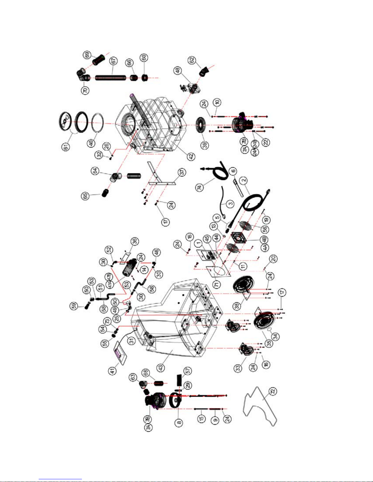
E1700 150 PSI

14
REF
PART NO.
DESCRIPTION
NOTES:
1
305-230
Switch, Rocker 20 Amp
2 315-015
Cord, 25’ Black 14/3 SJTW-A
3
315-040
Cord, Fan Muffin
4A
333-005
Fan, Muffin 4” (110v)
E1715
4B
333-006
Fan, Muffin 4” (220v)
E1715-20
5
335-015
Strain Relief, 12 Gauge
6 350-005
Strap Velcro
7A
355-400
Vacuum, 2 Stg (110v)
E1715
7B
355-500
Vacuum, 2 Stg (220v)
E1715-20
8
355-405
Vac Cap, Straight
9
355-225
Vac Spacer 3/8 x 2 1/2
10
400-010
Hex Nut 1/4 x 20 Zinc
11
400-130
Locknut, 10 x 24 Nylon SS
12
400-148
Locknut, 4 x 40 Nylon SS
Not Shown
13
400-165
Locknut, 1/2”
14
405-010
Bolt, 1/4 x 1 SS
15
405-050
Bolt, 1/4 x 3 1/2 Stove Zinc
16
405-615
CS, 1/4 x 1/2 SS (Hex HD)
17
405-620
CS, 1/4 x 3/4 SS (Hex HD)
18
410-125
SMS, 8 x 5/8 Pan Rob. S.S.
Not shown
19
410-175
MS, 10-24 x 2 1/2 Rob Zinc
20
410-215
MS, 10-32 x 3/8 FT Phil SS
21
410-225
SMS, 10 X 1/2 Pan Rob. Zinc
Not shown
22
415-020
LW, 1/4 Zinc
23
415-105
FW, 6 SS
Not shown
24
415-125
FW, 1/4 SS
25
415-156
FW, 1/2 SS
26
415-305
FNDW, 1/4 SS
27
420-015
Rivet, AL #48
Not shown
28
420-055
Rivet, AL/AL #46
Not shown
29
425-010
Clamp, #20 Hose 13/16 x 1 3/4
30
425-115
Clamp, Hose Silicone
31
430-010
Chain, 1/4 Brass
32
435-040
Handle, Cross M
33
455-075
Caster, 4” Swivel
34
455-052
Wheel Cap Dome
35
455-057
Wheel, 8” Grey/Black Hub
36
465-050
BRKT, E1700 Pump
37
465-080
Brace, D/B Tank
38
470-016
Axel, D/B Set V2
39
475-035
Gasket Vac 5 3/4
40
475-125
Gasket 6” Access Cover Clear
41
495-210
Lid, Solution Tank
42
495-220
Rec Tank
E1715 (110v & 220v)

15
43
495-225
Sol Tank
44
498-055
Plug, 1/2 Nylon
45
498-065
Plug, 7/8 Button
46
510-090
Shurflo Elbow, 90
47A
511-105
Pump, 150 PSI, 112v
E1715
47B
511-305
Pump, 150 PSI, 220v
E1715-20
48
545-100
Dump Valve, 1 1/2”
49
555-184
Elbow 45, Street 1/4
50
555-208
Elbow 90, 1/4 Street Extruded
51
555-254
Ferrule 3/8 Hose
52
555-326
Hose Barb 90, 3/8 Barb x 3/8 MPT
53
555-364
Hose Barb, 3/8 Barb x 1/4 MPT
54
555-512
Reducing ADPT, 3/8 FPT x 1/4 MPT
55
560-030
Screen, Acorn
56
560-325
Guard, Finger 4” Fan
57
570-010
Vac Hose 1 1/2” Wire Reinforced
58
572-041
L.P. Hose 3/8”
59
580-010
Q.C. 1/4” Fem (Closed)
60
585-025
Spin Fitting 1 1/2
61
585-210
Clear Cover, 6” C/W Ring
62
588-020
ABS Elbow 45, 1 1/2 SLP x SLP
63
590-010
PVC Elbow 1 1/4 90, S x S
64
590-020
PVC ELB 1 1/2” 90, S x FIPT
65
590-405
PVC Hose Barb 1 1/2” x MPT
66
590-415
PVC Adpt 1 1/2”, S x MPT
67
595-005
ABS Pipe, 1 1/2”
68
595-110
PVC Pipe, 1 1/4”
69
597-010
Float Screen Cage
70
597-061
Adpt (RM) 30 Degree
71
845-045
Control Panel
72
845-047
Plate Bottom
73
555-024
Bushing 3/8 M x 1/4 F
74
263-105
Prime line 4’ (Optional)

16
1700 150PSI DUAL 3 STAGE VAC

17
E1715 DUAL 3 STAGE VAC (110v & 220v)
REF
PART NO.
DESCRIPTION
NOTES:
1
305-230
Switch, Rocker 20 Amp
2 315-015
Cord, 25’ Black 14/3 SJTW-A
3 315-040
Cord, Fan Muffin
4A
333-005
Fan, Muffin 4” (110v)
E1715
4B
333-006
Fan, Muffin 4” (220v)
E1715-20
5
335-015
Strain Relief, 12 Gauge
6 350-005
Strap Velcro
7A
355-410
Vacuum, 3 Stg (110v)
E1715
7B
355-510
Vacuum, 3 Stg (220v)
E1715-20
8
355-405
Vac Cap, Straight
9 355-219
Vac Spacer 5/16 x 3
10
400-010
Hex Nut 1/4 x 20 Zinc
11
400-130
Locknut, 10 x 24 Nylon SS
12
400-165
Locknut, 1/2”
13
405-010
Bolt, 1/4 x 1 SS
14
405-060
Bolt, 1/4 x 4 Stove Zinc
15
405-615
CS, 1/4 x 1/2 SS (Hex HD)
16
405-620
CS, 1/4 x 3/4 SS (Hex HD)
17
410-125
SMS, 8 x 5/8 Pan Rob. S.S.
Not shown
18
410-175
MS, 10-24 x 2 1/2 Rob Zinc
19
410-215
MS, 10-32 x 3/8 FT Phil SS
20
410-225
SMS, 10 X 1/2 Pan Rob. Zinc
Not shown
21
415-125
FW, 1/4 SS
22
415-156
FW, 1/2 SS
23
415-305
FNDW, 1/4 SS
24
425-010
Clamp, #20 Hose 13/16 x 1 3/4
25
425-115
Clamp, Hose Silicone
26
430-010
Chain, 1/4 Brass
27
435-040
Handle, Cross M
28
455-075
Caster, 4” Swivel
29
455-052
Wheel Cap Dome
30
455-057
Wheel, 8” Grey/Black Hub
31
465-050
BRKT, E1700 Pump
32
465-080
Brace, D/B Tank
33
470-016
Axel, D/B Set V2
34
475-035
Gasket Vac 5 3/4
35
475-125
Gasket 6” Access Cover Clear
36
495-210
Lid, Solution Tank
37
495-220
Rec Tank
38
495-225
Sol Tank
39
498-055
Plug, 1/2 Nylon
40
510-090
Shurflo Elbow, 90
41A
511-105
Pump, 150 PSI, 110v
E1715
41B
511-305
Pump, 150 PSI, 220v
E1715-20

18
42
545-100
Dump Valve, 1 1/2”
43
555-024
Bushing 3/8 M x 1/4 F
44
555-184
Elbow 45, Street 1/4
45
555-208
Elbow 90, 1/4 Street Extruded
46
555-364
Hose Barb, 3/8 Barb x 1/4 MPT
47
555-512
Reducing ADPT, 3/8 FPT x 1/4 MPT
48
560-030
Screen, Acorn
49
560-330
Guard, Finger 6” Fan
50
570-010
Vac Hose 1 1/2” Wire Reinforced
51
572-041
L.P. Hose 3/8”
52
580-010
Q.C. 1/4” Fem (Closed)
53
585-025
Spin Fitting 1 1/2
54
585-210
Clear Cover, 6” C/W Ring
55
588-020
ABS Elbow 45, 1 1/2 SLP x SLP
56
590-010
PVC Elbow 1 1/4 90, S x S
57
590-020
PVC ELB 1 1/2” 90, S x FIPT
58
590-405
PVC Hose Barb 1 1/2” x MPT
59
590-415
PVC Adpt 1 1/2”, S x MPT
60
595-005
ABS Pipe, 1 1/2”
61
595-110
PVC Pipe, 1 1/4”
62
597-010
Float Screen Cage
63
597-061
Adpt (RM) 30 Degree
64
845-045
Control Panel
65
845-047
Plate Bottom
66
555-326
Hose Barb 90, 3/8 Barb x 3/8 MPT
67
415-020
LW, 1/4 Zinc
68
420-015
Rivet, AL #48
Not shown
69
420-055
Rivet, AL/AL #46
Not shown
70
263-105
Prime Line 4’ (Optional)

19
E1700 150PSI HEATER MATE

20
E1715 H.M (110v & 220v)
REF
PART NO.
DESCRIPTION
NOTES:
1
305-210
Toggle Switch
2 305-225
Switch Plate, ON-OFF
3 305-230
Switch, Rocker 20 Amp
4
315-015
Cord, 25’ Black 14/3 SJTW-A
5
315-040
Cord, Fan Muffin
6A
320-110
Lamp, Panel (110v)
E1715-10
6B
320-900
Lamp, Panel (220v)
E1715-20-10
7A
333-005
Fan, Muffin 4” (110v)
E1715-10
7B
333-006
Fan, Muffin 4” (220v)
E1715-20-10
8
335-015
Strain Relief, 12 Gauge
9 350-005
Strap Velcro
10A
355-400
Vacuum, 2 Stg (110v)
E1715-10
10B
355-500
Vacuum, 2 Stg (220v)
E1715-20-10
11
355-405
Vac Cap, Straight
12
355-225
Vac Spacer 3/8 x 2 1/2
13
400-010
Hex Nut 1/4 x 20 Zinc
14
400-130
Locknut, 10 x 24 Nylon SS
15
400-165
Locknut, 1/2”
16
405-010
Bolt, 1/4 x 1 SS
17
405-056
Bolt, 1/4 x 4 Stove Zinc
18
405-615
CS, 1/4 x 1/2 SS (Hex HD)
19
405-620
CS, 1/4 x 3/4 SS (Hex HD)
20
410-175
MS, 10-24 x 2 1/2 Rob Zinc
21
410-215
MS, 10-32 x 3/8 FT Phil SS
22
415-020
LW, 1/4 Zinc
23
415-125
FW, 1/4 SS
24
415-156
FW, 1/2 SS
25
415-305
FNDW, 1/4 SS
26
425-010
Clamp, #20 Hose 13/16 x 1 3/4
27
425-115
Clamp, Hose Silicone
28
425-130
Clamp, Tube 3”
29
430-010
Chain, 1/4 Brass
30
435-040
Handle, Cross M
31
455-075
Caster, 4” Swivel
32
455-052
Wheel Cap Dome
33
455-057
Wheel, 8” Grey/Black Hub
34
465-050
BRKT, E1700 Pump
35
465-080
Brace, D/B Tank
36
470-016
Axel, D/B Set V2
37
475-035
Gasket Vac 5 3/4
38
475-125
Gasket 6” Access Cover Clear
39A
490-005
Foamed Casing, Round 1850W (110v)
E1715-10
39B
490-006
Foamed Casing, Round 1850W (220v)
E1715-20-10
40
495-210
Lid, Solution Tank

21
41
495-220
Rec Tank
42
495-225
Sol Tank
43
498-055
Plug, 1/2 Nylon
44
510-090
Shurflo Elbow, 90
45A
511-105
Pump, 150 PSI, 110v
E1715-10
45B
511-305
Pump, 150 PSI, 220v
E1715-20-10
46
545-100
Dump Valve, 1 1/2”
47
550-035
Check Valve 1/4
48
555-024
Bushing 3/8 M x 1/4 F
49
555-184
Elbow 45, Street 1/4
50
555-208
Elbow 90, 1/4 Street Extruded
51
555-210
Elbow 90, 3/8 MPT x 1/4 MPT
52
555-364
Hose Barb, 3/8 Barb x 1/4 MPT
53
555-512
Reducing ADPT, 3/8 FPT x 1/4 MPT
54
560-030
Screen, Acorn
55
560-325
Guard, Finger 4” Fan
56
570-010
Vac Hose 1 1/2” Wire Reinforced
57
572-041
L.P. Hose 3/8
58
572-125
Pulse Hose, 3/8
59
580-010
Q.C. 1/4” Fem (Closed)
60
581-060
Crimp Ftng, 3/8 Pulse Hose 1/4 MPT
61
581-065
Crimp Ftng, 3/8 Pulse Hose 1/4 MPT SVL
62
585-025
Spin Fitting 1 1/2
63
585-210
Clear Cover, 6” C/W Ring
64
588-020
ABS Elbow 45, 1 1/2 SLP x SLP
65
590-010
PVC Elbow 1 1/4 90, S x S
66
590-020
PVC ELB 1 1/2” 90, S x FIPT
67
590-405
PVC Hose Barb 1 1/2” x MPT
68
590-415
PVC Adpt 1 1/2”, S x MPT
69
595-005
ABS Pipe, 1 1/2”
70
595-110
PVC Pipe, 1 1/4”
71
597-010
Float Screen Cage
72
597-061
Adpt (RM) 30 Degree
73
845-045
Control Panel
74
845-047
Plate Bottom
75
263-013
HP Hose 28”
76
263-105
Prime Line 4’ (Optional)

22

23
8000 P UMP TRO UBLE S HO O TING GUIDE
TROUBLE PROBABLE CAUSE TO CORRECT
Pump starts but 1. Not enough volt 1. Provide correct volt
no prime 2. No liquid 2. Fill liquid
3. Leak in inlet line 3. Correct leak
4. Air lock 4. Bleed air
5. Bad valves 5. Replace valves
6. Mounted too high 6. Lower mounting
7. Check valve stuck 7. Clean/replace, ck valve
8. Debris in pump 8. Clean/replace damaged
9. Clogged filter 9. Clean/replace filter
10. Line connection backward 10. Connect line to proper
port
11. Missing VLV.HSG O ring 11. Place O-ring
External leak 1. Ruptured diaphragm 1. Replace diaphragm
from pump head 2. Piston SC loose 2. Tighten piston screw
drain 3. Pinched diaphragm 3. Replace diaphragm
4. Cross thread piston scr. 4. Properly assemble
External leak 1. Ruptured SW diaphragm 1. Replace SW diaphragm
from switch 2. Pinched SW diaphragm 2. Replace SW diaphragm
3. Loose switch screw 3. Secure switch screws
Vaucum leak 1. Pinched diaphragm 1. Replace diaphragm
2. Cracked upper housing 2. Replace upper housing
3. Loose inline fitting 3. Tighten fi tti ng
4. Cracked valve housing 4. Replace valve housing
Rough pump 1. Bad motor 1. Replace
2. Bad drive 2. Replace
3. Screws loose 3. Tighten screws
Low performance 1. Clogged filter 1. Clean/replace
2. Bad motor 2. Replace
3. Improper voltage 3. Provide proper voltage
4. Bad valves 4. Replace
5. Improper plumbing 5. Correct plumbing
6. Loose fasteners 6. Secure all fasteners

24
8000 PUMP TROUBLE SHOOTING GUIDE
TROUBLE PROBABLE CAUSE TO CORRECT
Pump will not 1. Bad motor 1. Replace
start 2. Bad rectifier 2. Replace motor
3. Bad wire connection 3. Correct connection
4. Bad micro switch 4. Replace
5. Bad brushes 5. Replace motor
6. Frozen drive 6. Replace drive
7. Blown fuse 7. Replace
8. No power to pump 8. Connect power
No shut off 1. No liquid 1. F ill liquid
2. Air lock 2. Purge line check install
3. Shut set to high 3. Set to correct shutoff
(by-pass SW combo)
4. Bad micro switch 4. Replace

25
E1715 WIRING

26
E1715 DUAL STAGE VAC
WIRING

27
E1715 HEATER MATE WIRING P. 1

28
E1715 HEATER MATE WIRING P. 2
29

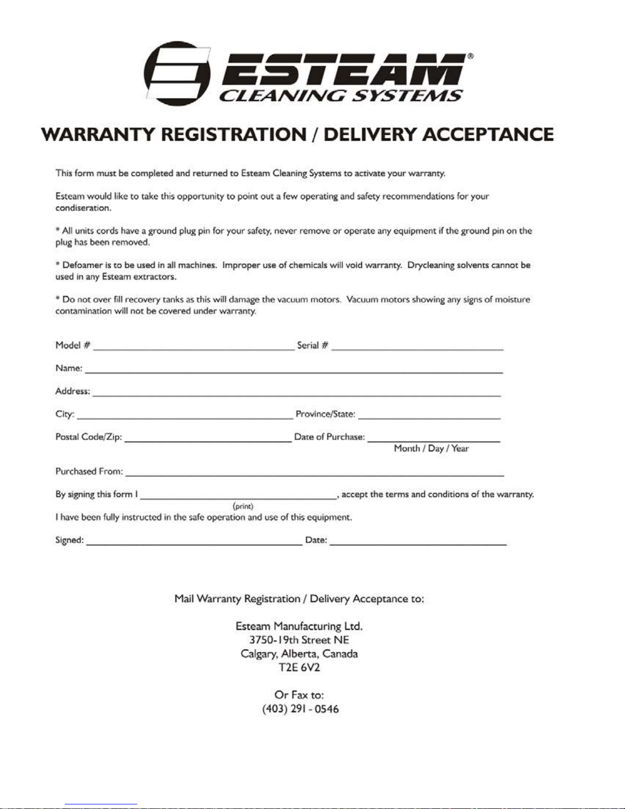
30
ESTEAM® CLEANING SYSTEMS
E-Series Extractor Warranty
E1700, E1000, E600, E250
NOTICE: REVIEW THIS WARRANTY CAREFULLY AS THIS DOCUMENT
CONTAINS LIMITATIONS AND EXCLUSIONS.
PART I:
Esteam Manufacturing Ltd. (hereinafter referred to as "Esteam") warrants each new ESeries Extractor, subject to the limitations as defined in the specific details of its warranty
coverage defined below.
LIMITE D LIFETIME HOUSING WARRANTY COVERAGE:
Esteam warrants the E-Series Polyethylene Machine Housing Unit to be free from defects
in material and workmanship (including cracking, leaking or deterioration) for the life of
the unit, expressly subject to the limitations stated herein.
In the event a defect occurs in a E-Series Housing Unit within five years of receipt by the
original customer, Esteam will, if satisfied on its examination that the failure is due to
defective material or workmanship, repair or replace the E-Series Housing Unit, at no cost
to the original customer, other than as maybe provided for in this warranty.
In the event a defect occurs in a E-Series Housing Unit subsequent to five years (and
thereafter for life) of receipt by the original customer; Esteam will, if satisfied on its
examination, that the failure is due to defective material or workmanship, provide to the
original customer only, a new Housing Unit, at 50% of the then published retail pricing
basis, used by Esteam.
90 DAY LIMITED WARRANTY COVERAGE:
Esteam warrants all switches, vacuum hoses and solution hoses, heatermate thermostats
and thermo cut-outs to be free from defects in material and workmanship, for any defect
occurring within 90 days of receipt by the original customer of the E-Series Extractor; and
further subject to the limitations stated below. 90 day on labor, subject to Esteam’s
approval; hourly labor credit is set by Esteam.
12 MONTH WARRANTY COVERAGE:
Subject to the Limited Lifetime Warranty and the 90 Day Limited Warranty; Esteam
warrants all remaining i tems on t he E-Series Extractor to be free from defect in material or
workmanship (excluding any labor charges) for a period of 12 months from date of receipt
of the unit by the original customer; and further subject to the limitations stated below.

31
PART II - REPLACEMENT PARTS (UNDER WARRANTY)
Replacement warranty parts will be genuine Esteam parts, or parts of similar kind and
quality.
All replacement warranty parts are warranted to be free from defects in materials or
workmanship from the date of the original unit purchase for the balance of the original
warranty period namely: 90 days, 12 months, or the Lifetime, whichever is applicable; all
in accordance with the terms of Part I, of this warranty.
P ART III - LIMITATIONS ON WARRANTY COVERAGE
WHAT IS NOT COVERED:
Notwithstanding any other term or covenant of Esteam contained herein, the following
provisions shall apply:
(i) No warranty is provided for any Esteam product which has failed as a result of
freezing, fire, misuse, alteration, improper amps or voltage, accidental damage,
improper maintenance, unauthorized repairs, alterations, abuse, neglect or
operation of a Esteam product not expressly recommended or contemplated by
Esteam; and
(ii) No warranty is provided for mechanical or electrical breakdown caused by scale,
hard water buildup, improper use of chemicals or resins, damage due to
environmental conditions, and acts of God, or other events beyond the control of
Esteam; and
(iii) No warranty is provided for mechanical or electrical breakdown or failure of an
Esteam product resulting from ordinary wear and tear, or the consequences
thereof; including but not limited to the gradual reduction of the operating
performance of the product. The determination of what is or is not ordinary wear
and tear is at the sole discretion o f Estea m; and
(iv) No warranty is provided for damage caused by the failure of non-warranted parts
and/or accessories, even if warranted parts are damaged as a result of the failure
of a non-warranted part; and
(v) No warranty is provided for damage resulting from failure by the customer to
maintain scheduled maintenance requirements. The Esteam system has many
parts which must either be replaced or checked for wear on a regular basis;
including but not limited to replacement filters and lubricants. This system requires
regular maintenance, service and attention by the customer; and
(vi) No warranty is provided as to any extra expenses incurred by the customer,
including but not limited to economic, incidental, consequential loss or damage
(e.g. all labour charges, rental equipment, down time, lodging, commercial or
business loss of any nature or kind due to product failure); whether di rec t or
indirect, exemplary or punitive damage or loss, and whether in contract, tort or
otherwise; and

32
(vii) No warranty is provided as to failure of any cosmetic item or finish, labeling, silk
screening, decals, paint, trim or other similar decorative items.
(viii) Brass, rubber and synthetic rubber parts (e.g. "O" rings, diaphragms, gaskets,
seals, grommets) are considered expendable in normal use, and are therefore not
included in any warranty by Esteam.
PART IV - EXCLUSION OF LIABILITY
Esteam makes no warranties or representations, either expressed or implied, oral or
written, in fact, or by operation of law, or otherwise, except as expressly stated herein as
to the 90 day Limited, 12 month and Lifetime Extended warranties. Esteam, its officers,
directors, agents, dealers and its affiliates (and their respective officers, directors, agents
and dealers) shall not be liable to the customer nor to any party for any
liability, including withou t limitation, strict liability, liability for loss, injury or damage due
directly or indirectly to the use or operation of the Esteam product; consequential,
exemplary and/or punitive damage or loss, whether in contract, tort, or otherwise.
PART V - RETURN GUI DE LINES
Defective items must be replaced through a local Esteam Distributor. Replacement parts
will be sent via prepaid regular ground service to the distributor. The defective part must
be returned F.O.B. factory within 30 days including a letter providing the machine's serial
number, date of purchase, material return authorization number, and customer name. If
applicable, credit will be issued after the item has been evaluated by Esteam. Failure to
comply with return policy will void the warranty on that item.
PART VI - CREDIT POLICY
All customers purchasing parts through an Esteam distributor must arrange credit directly
with that distributor.
PART VII - OUTSIDE SOURCE WARRANTY REPAIRS
At the sole discretion of Esteam, it may be necessary to perform warranty/repairs at an
outside source. An estimate must be submitted to and approved by Esteam prior to work
being performed. Failure to do so will result in denial of your warranty claim.
PART VIII - TRANSFERABILITY
This warranty is not transferable to any subsequent owner.

33
PART IX - NOTICE - CUSTOMER OBLIGATIONS
(i) Your responsibility as a customer includes but is not limited to cleaning, lubricating,
seasonal maintenance (e.g. winterizing), replacement of worn parts and all regular
scheduled or unscheduled mai n tenance.
(ii) Any claim for warranty must be presented to Esteam or its authorized dealer, prior
to the expiration of the time limitations specified and not thereafter, otherwise any
warranty is void.
(iii) Notwithstanding the generality of the foregoing customer obligations, Esteam does
hereby bring to the attention of the customer, these specific maintenance operating
requirements of the E-Series Extractor to validate its warranty:
(a) Chemical Warning:
Any improper use of chemicals shall void any Esteam warranty and
thusly exclude any liability by Esteam. No dry cleaning chemical may be
used in a E-Series Extractor; - as any such use may result in fire or
pump/motor damage. A defoamer solution must be used bycustomer to
limit foaming in the recovery tank.
(b) Vacuum Motor s :
Require use of a defoamer. A vacuum motor showing moisture
contamination on interior components shall void any warranty by
Esteam.
(c) Pumps:
All pumps require daily flushing with clean water after use.
(d) Internal Heatermate:
The internal heater must be flushed with clean water after every use. Any
build up of hard water deposits or chemical build up within the internal
heater will void any Esteam warranty thusly exclude any liability of Esteam.
The foregoing constitutes Esteam's entire warranty and no other warranty, liability,
contingency or responsibility, direct, indirect, consequential or in any other way connected
with the sale or operation of Esteam machines or chemical product is expressed or
implied.
E-Series Extractor Warranty
Esteam Manufacturing Ltd. 3750-19th Street NE
Calgary, AB T2E 6V2 1-800-653-8338
 Loading...