

Page 1

USER DRIVEN MANUAL*
Any feedback, changes, or advice, we are
glad to hear it. Please contact us at
— WARNING —
Read all instructions before beginning
installation or use of this gate opener.
This operator exerts a high level of force.
Exercise caution at all times and stay
clear of the system during operation.
EstateSwing.com
LOOK INSIDE
For QR codes you can scan
with your smartphone to view
supplementary videos
E-S 300 / 302 Classic Series
INSTRUCTION MANUAL
*Estate Swing’s unique user driven manuals are constantly updated by installers and homeowners like yourself. We improve by
hearing and applying your feedback.
Page 2

Estate Swing Summary of Functions
The Estate Swing is only to be used for vehicular swing gates in a Class I setting.
CLASS I:
The Estate Swing automated system was designed and built for controlling vehicle access. Do
not use for any other purpose.
The external automation with an electro-mechanical non-reversing linear arm automates residential swing-leaf gates with leaves of up to 12’ in length. It consists of an irreversible electromechanical operator with built in opening and closing limits and utilizes a worm screw system.
The irreversible system ensures the gate is mechanical locked when the motor is not operating. A lock still needs to be installed if security or high winds are a concern. A manual release
makes it possible to move the gate in the event of a power-cut or fault.
A vehicular gate opener (or system) intended for use in a home of one-to-four
single family dwelling, or a garage or parking area associated therewith.
For Your Assistance
Keep this manual safely stored after installation
Serial Number
Date of Purchase
Place of Purchase
Have this information on hand while handling all service and warranty
issues.
E-S 300 / 302 Classic Series Instruction Manual
Page 3

Table of Contents
The table of contents are listed to assist you locating a desired section. We do however strongly
suggest studying every page of the instruction manual before attempting installation.
Section 1: Review of Specifications, Warnings, and Tools
Specifications of the Estate Swing and Components 1.1
Parts List 1.2
System Overview & Preliminary Checks 1.3
Tools Needed for Installation 1.4
Section 2: Installation of Mounting Brackets
Manual Operation, Restoring Automation 2.1
Pull to Open Illustration 2.2
IMPORTANT: Determining Setback—Pull to Open 2.3
Installation of Operator—Pull to Open 2.4-5
Push to Open Illustration 2.6
IMPORTANT: Determining Setback—Push to Open 2.7
Installation of Operator—Push to Open 2.8-9
Section 3: Gate Operator Mounting, Wiring Motors and Power
Mounting Gate Operator(s) 3.1
Check Usage of Stroke 3.2
Control Box & Running Wires 3.3
Easy Wiring Under Driveway 3.4
Removing Terminal Strips for Wiring 3.5
Wiring the Operator Arms(s) (Pull & Push to Open) 3.6-7
Temporary Safety Jumpers & Dip Switch Settings 3.8
Power 3.9
Section 4: Start Up and Operation
Find Limit Positions 4.1
First Run 4.2
Determine Run Time 4.3
Operating Parameters Customization 4.4
433 Plug-In Receiver 4.5-.6
Section 5: Maintenance, Troubleshooting, and Accessories
Maintenance 5.1
Troubleshooting 5.2-.4
Control Board Overview 5.5-.8
Accessories 5.9-.10
E-S 300 / 302 Classic Series Instruction Manual
Page 4

SECTION 1:
Review of Specifications, Warnings,
and Tools
E-S 300 / 302 Classic Series Instruction Manual
Page 5

Page 6

Specifications
MODEL Estate Swing E-S 300 / 302
Power Supply 24V AC, 50VA to 120 VA
Backup Battery Voltage 24V DC
Current (A) 3
Travel (in.) 12
Cycles per hour 50% Duty Cycle / Aprox. 35
Operating Ambient Temperature -20 to 130 F
Protection Class IP44
Gate leaf max length (ft.) Up to 12
Gate leaf max weight (lbs.) Up to 600
Operator Type Screw Drive
Operator Weight 14 lbs
Gate Weight / Length Ratio 6’ 8’ 10’ 12’
100 lbs X X X X
200 lbs X X X X
300 lbs X X X X
400 lbs X X
500 lbs X X
600 lbs X
The above chart represents the maximum weight and length combinations that
this gate opener can handle. The lengths and weights are either for a single
gate or for a single leaf of a dual gate.
E-S 300 / 302 Classic Series Instruction Manual
1.1
Page 7

Estate Swing Parts List
Master or Single Operator Slave Operator (if applicable)
A. Control Box with Control Board
B. Operator Arm with 42” of Wire
C. Key
D. Connector Pins and C Rings
E. Transformer
F. Post Mounting Brackets
G. Gate Mounting Bracket
Not Shown:
•Mounting Hardware
1 - 3/8”x1 3/8” Hex bolts, washer, nut
1 - 5/16”x 1 3/8” Hex bolt, washer, nut
2 - 3/8”x 2” Carriage bolt, washers, nut
1 - 1/4” x 2” Hex bolt, washers, nut
A. N/A
B. Operator Arm with 42” of Wire
C. Key
D. Connector Pins and C Rings
E. N/A
F. Post Mounting Brackets
G. Gate Mounting Bracket
Not Shown:
•Additional Wire
•Mounting Hardware
1 - 3/8”x1 3/8” Hex bolts, washer, nut
1 - 5/16”x 1 3/8” Hex bolt, washer, nut
2 - 3/8”x 2” Carriage bolt, washers, nut
1 - 1/4” x 2” Hex bolt, washers, nut
E-S 300 / 302 Classic Series Instruction Manual
1.2
Page 8

Standard System Overview and Safety Zone
The system displayed below is a recommended standard system. Other approved accessories
can be installed. Photo sensors and a flashing light indicating gate movement is recommended for safety purposes.
1,2 Estate Swing Operator • 3 Photocells (not included) • 4 Control board • 5 N/A 6 Push but-
ton opening device (not included) • 7 Receiver extension (not included) • 8 24Vdc flashing
lamp (not included) • 9 Positive stop (not included) • 10 AC transformer
Notes: 1) When laying electrical cables, use appropriate rigid and/or flexible tube
2) Do not run any wires in the same conduit as 110 AC power that may be in
the area. This will cause danger of electrocution.
IMPORTANT: Preliminary Checks
To ensure safety and an efficiently operating automated system, make sure the following conditions are observed.
• The gate and post must be suitable for being automated. Check that the structure is
sufficiently strong and rigid, and its dimensions and weights conform to those Indicated
on page 1.
• Make sure the gates move smoothly without any irregular friction during entire travel.
• Make sure the hinges are in good condition. Ball bearing hinges are necessary for
gates weighing over 200 lbs. or over 10’ in length.
• Make sure the gate is plumb and level.
• The gate post must be secured in the ground with concrete. This will prevent alteration
of alignments and leveling during installation and during cycles.
E-S 300 / 302 Classic Series Instruction Manual
1.3
Page 9

Tools Needed for Installation
• Power Drill
• Crescent Wrench
• Flat Head Screwdriver
• Hacksaw/Sawzall
• Phillips Head Screwdriver
• Small Flathead Screwdriver
Other items may be needed prior to commencing installation. BOLDED items are necessary
to all applications.
• Positive post, bracket or door stop. Although the Estate Swing 300 / 302 features built in limit
switches it is highly recommended to have positive stops.
• 16 gauge, 2 conductor stranded direct burial low voltage wire will be required to run pow-
er to your operator. Length is determined by distance between transformer or solar power
supply and the control box.
• 4 - 3/8” Carriage Bolts will be needed to connect the 2 “L” shaped brackets to the post.
Length will be determined by the size of your posts.
• A metal support bracket may be needed to achieve the appropriate desired setback. The
metal support bracket will be bolted or welded to your post to give a larger amount of
space to mount the provided mounting bracket.
• A voltage meter and digital camera may be necessary to run diagnostic checks.
• If your transformer is going to be plugged into an outdoor outlet you will need to weather-
proof that outlet and transformer. Electrical boxes or plug covers can be obtained from a
local hardware store to accommodate both the plug and transformer.
• Hardware to attach the control box to a post or fence.
• C-Ring Pliers
• Tape Measure
• Level
• Wire Strippers
• C-clamps
• 3/8”, 1/4”, 5/16” Drill Bits
Protect all ingoing and outgoing wires with a surge suppressor.
!
Consult your local dealer for more information.
E-S 300 / 302 Classic Series Instruction Manual
1.4
Page 10

SECTION 2:
Installation of Mounting Brackets
E-S 300 / 302 Classic Series Instruction Manual
Page 11

Page 12

Manual Operation
1) Lift lock cover cap off.
2) Insert and turn provided key.
3) The operator can now be pull or push
open.
4) Replace lock cover to protect lock
from water and debris.
To exit manual mode, repeat the
above steps.
Restoring Automation
To maintain the proper performance of your emergency release please perform the following service for your motor once per year.
1. Remove the emergency release cap
2. Spray some WD-40 or other spray lubricant into the release lock.
3. Allow the lubricant to soak in.
4. Apply a liberal dab of petroleum
based jelly or wheel bearing
grease to coat the release lock.
5. Put the cap securely back in
place.
E-S 300 / 302 Classic Series Instruction Manual
2.1
Page 13

IMPORTANT: Pull to Open Operation
This means the gate operator is mounted on the inside of the property
and pulls your gate in towards the property. If you are going to use push
to open operation “X” out the next 3 pages and use the push to open
section instructions.
E-S 300 / 302 Classic Series Instruction Manual
2.2
Page 14
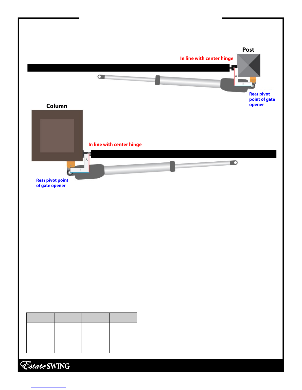
IMPORTANT: Pull to Open Operation
Below are 2 common examples of setback mountings.
These are not the only options for mounting.
There are 4 factors to keep in mind when finding the setback mounting:
1) The (A) measurement is perpendicular from the gate in the CLOSED position.
2) There must be clearance for your gate opener to attach to the gate in the closed position. This is most
commonly an issue on columns. Re-positioning of the hinges or Push-To-Open operation may be required
to achieve clearance.
3) The brackets do not and must not move after installation.
4) The "L" shape brackets can be mounted anywhere on the post or column. They can be mounted on a
separate post or fence as well. The only factor of importance is that when mounting of the brackets is
done the hole in the boomerang bracket that the gate opener mounts on matches the setback on this
page.
It is best to C-Clamp brackets on and test arm movement clearance before permanently attaching
them.
Variations to the ideal setback can be made, so long as the total is less than the combined measurements for the desired opening arc and the motor body is more than 2 inches away from the gate in both
the open and closed position. (setback variations significantly reduces the length and weight capacity of
the operator)
Use one of the rows below:
A B Sum a
To determine the position of the gate mounting
bracket (above is for the post mounting brack-
4 ¾" 5 ¼" 10 110°
5 ¼" 5 ¼" 10 ½ 100°
et) refer to step 13 in the section “Installation of
Operator”
5 ½" 5 ½" 11 90°
E-S 300 / 302 Classic Series Instruction Manual
2.3
Page 15
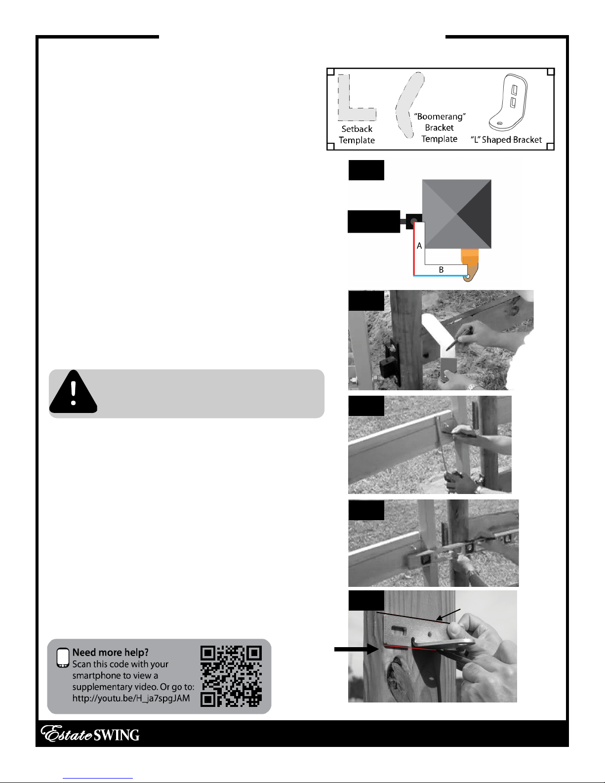
Installation of Operator —Pull-to-Open
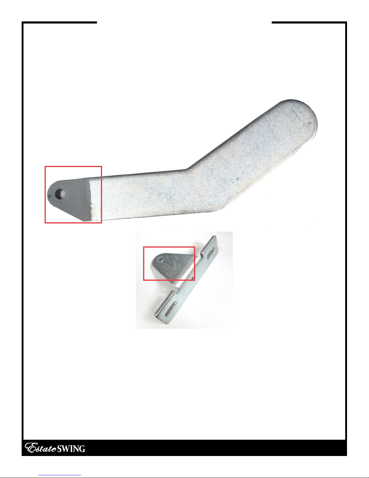
1. Locate the set back and boomerang bracket
templates found in the box to determine the
proper setback.
2. Find the proper setback for your operator (from
previous page). Hold the lower “L” shaped
bracket along with the boomerang bracket template against the post near the hinge. [See Fig. 1]
Mark how much of the boomerang bracket you
will trim off on the template. The hole on the end
of the boomerang bracket should be in the setback position.
3. Trim boomerang bracket template, then double check setback positioning. Using the template, mark the boomerang bracket for cutting.
[See Fig. 2]
4. Cut off the excess length (if any) of the boomerang bracket using a sawzall or hacksaw.
CAUTION: Observe all safety precautions recommended by manufacturer
of the cutting tool.
5. Using a measuring tape, measure vertically to
find the center of the horizontal mount on the
gate, then place a mark. [See Fig. 3]
6. Utilizing a level, measure from the center of the
horizontal mount of the gate to the post to the
get bracket position. Place a mark on the post at
this point. [See Fig. 4]
7. Temporarily position the gate bracket on the
post. Align the top of the gate bracket with the
marking created in the previous step. Make an
additional mark at the bottom of the gate bracket. This will mark the position for the top of the
lower “L” shaped bracket. [See Fig. 5]
Fig. 1
Fig. 2
Fig. 3
Fig. 4
Fig. 5
Original Line
E-S 300 / 302 Classic Series Instruction Manual
2.4
Page 16

Installation of Operator —Pull-to-Open
BEFORE PERMANENTLY ATTACHING ANY BRACKETS, BE SURE TO TEST ARM MOTION AND
CLEARANCE.
8. Place the lower “L” shaped bracket so the top of the
bracket is aligned with the bottom marking on the post.
Mark then drill and attach the bracket using 3/8” car-
riage bolts. [See Fig. 6]
Check “L” shaped bracket for levelness before putting
in the second bolt.
9. Place the upper “L” shaped bracket and the boomerang bracket on the lower “L” shaped bracket. Posi-
tion the brackets in the setback that is being used.
10. With the 3 brackets clamped together, mark then
drill the upper “L” shaped bracket in place and attach
it using 3/8” carriage bolts. [See Fig. 7]
11. Drill through the center hole of the “L” shaped set to
penetrate the boomerang bracket. Double check the
setback on the boomerang bracket.
12. Drill the set hole through all 3 brackets using a 5/16”
drill bit in an area behind the first hole. Secure the hole
with a 5/16” bolt and the provided nuts and lock wash-
ers. [See Fig. 8]
13. WITH THE GATE IN THE CLOSED POSITION measure 38”
from the center of the hole on the boomerang bracket
to the center of the hole on the gate bracket - this
should be the position of the gate bracket on the
closed gate. [See Fig. 9]
14. Additionally measure and mark the gate mounting
bracket so that it is vertically centered on the horizontal
bar.
15. To ensure that the gate mounting bracket is leveled,
secure one side of the bracket, check for levelness, and
secure the other side with provided carriage bolts, nuts,
and washers. [See Fig. 10]
Fig. 6
Fig. 7
Fig. 8
Fig. 9
Fig. 10
E-S 300 / 302 Classic Series Instruction Manual
2.5
Page 17
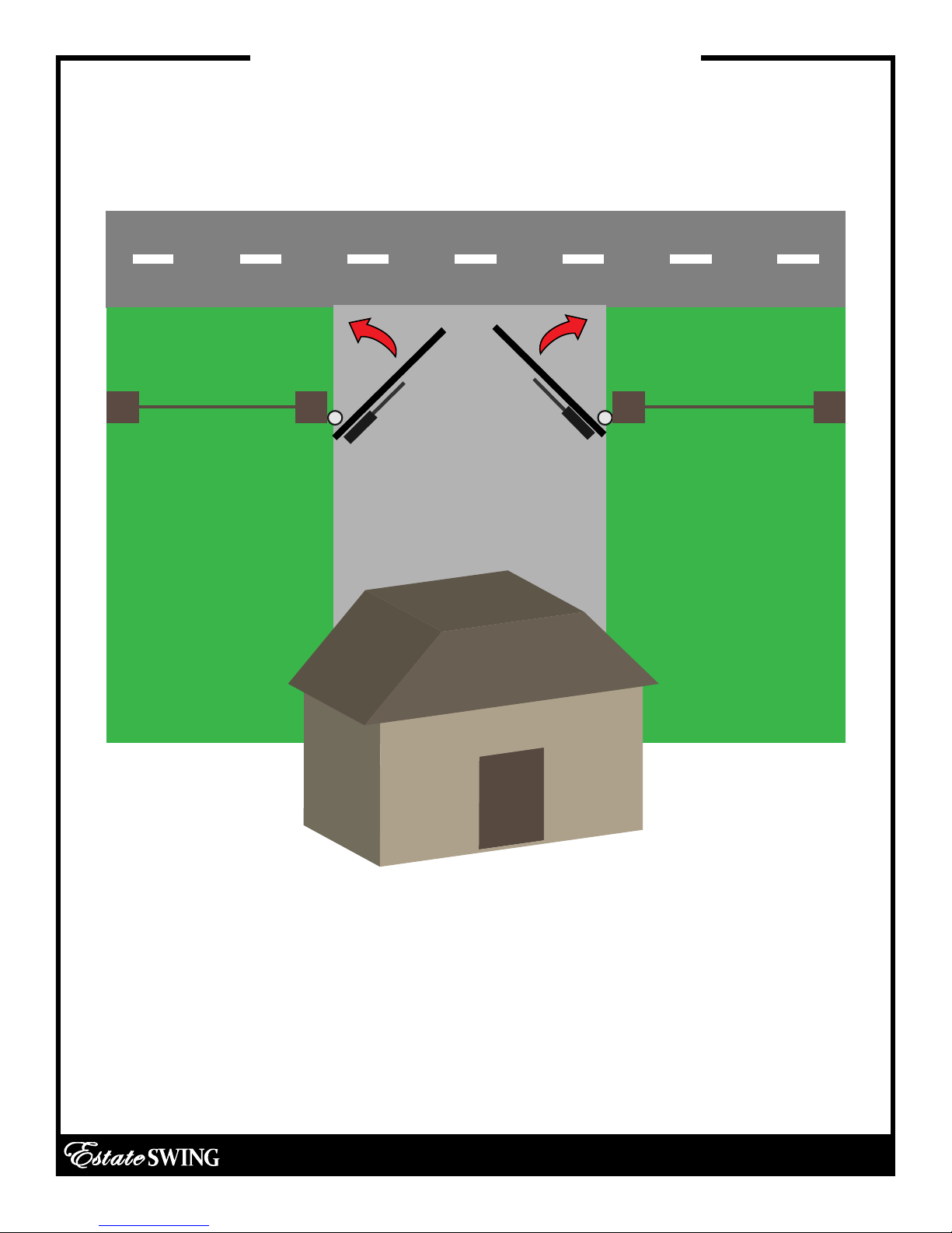
IMPORTANT: Push-to-Open Operation
This operation is commonly used if your driveway slopes up after the gate, preventing
it from swinging in. This means the gate operator is mounted on the inside of the property and pushes your gate out away from the property.
E-S 300 / 302 Classic Series Instruction Manual
2.6
Page 18

IMPORTANT: Determining Correct Setback
Below are 2 common examples of setback mountings. These are not the only options for
mounting.
There are 4 factors to keep in mind when finding the setback mounting:
1) The (A) measurement is perpendicular from the gate in the CLOSED position.
2) There must be clearance for your gate opener to attach to the gate in the closed position. This is
most commonly an issue on columns. Re-positioning of the hinges or Push-To-Open operation may be
required to achieve clearance.
3) The brackets do not and must not move after installation.
4) The "L" shape brackets can be mounted anywhere on the post or column. They can be mounted on
a separate post or fence as well. The only factor of importance is that when mounting of the brackets is
done the hole in the boomerang bracket that the gate opener mounts on matches the setback on this
page.
It is best to C-Clamp brackets on and test arm movement clearance before permanently attaching
them.
To determine the position of the gate mounting bracket (above is for the post mounting bracket) refer
to step 13 in the section “Installation of operator - PTO”
Use one of the rows below:
A B Sum a
4 ¾" 5 ¼" 10 110°
5 ¼" 5 ¼" 10 ½ 100°
5 ½" 5 ½" 11 90°
Variations to the ideal setback can be made, so long
as the total is less than the combined measurements for
the desired opening arc and the motor body is more
than 2 inches away from the gate in both the open and
closed position. (variations significantly reduces the
length and weight capacity of the operator)
E-S 300 / 302 Classic Series Instruction Manual
2.7
Page 19
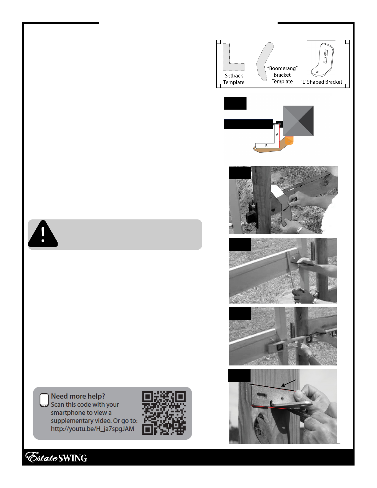
Installation of Operator — Push-to-Open
1. Locate the set back and the boomerang
bracket templates found in the box to determine
the proper setback.
2. Find the proper setback for your operator (from
previous page). Hold the lower “L” shaped
bracket along with the boomerang bracket template against the post near the hinge. [See Fig. 1]
Mark how much of the boomerang bracket you
will trim off on the template. The hole on the end
of the boomerang bracket should be in the setback position.
3. Trim boomerang bracket template, then double check setback positioning. Using the template, mark the boomerang bracket for cutting.
[See Fig. 2]
4. Cut off the excess length (if any) of the boomerang bracket using a sawzall or hacksaw.
Caution: Observe all safety precautions
recommended by manufacturer of the
cutting tool.
5. Using a measuring tape, measure vertically to
find the center of the horizontal mount on the
gate, then place a mark. [See Fig. 3]
6. Utilizing a level, measure from the center of the
horizontal mount of the gate to the post to the
get bracket position. Place a mark on the post at
this point. [See Fig. 4]
7. Temporarily position the gate bracket on the
post. Align the top of the gate bracket with the
marking created in the previous step. Make an
additional mark at the bottom of the gate bracket. This will mark the position for the top of the
lower “L” shaped bracket. [See Fig. 5]
Fig. 1
Fig. 2
Fig. 3
Fig. 4
Fig. 5
Original Line
E-S 300 / 302 Classic Series Instruction Manual
2.8
Page 20
Installation of Operator — Push-to-Open
BEFORE PERMANENTLY ATTACHING ANY BRACKETS, BE SURE TO TEST ARM MOTION AND
CLEARANCE.
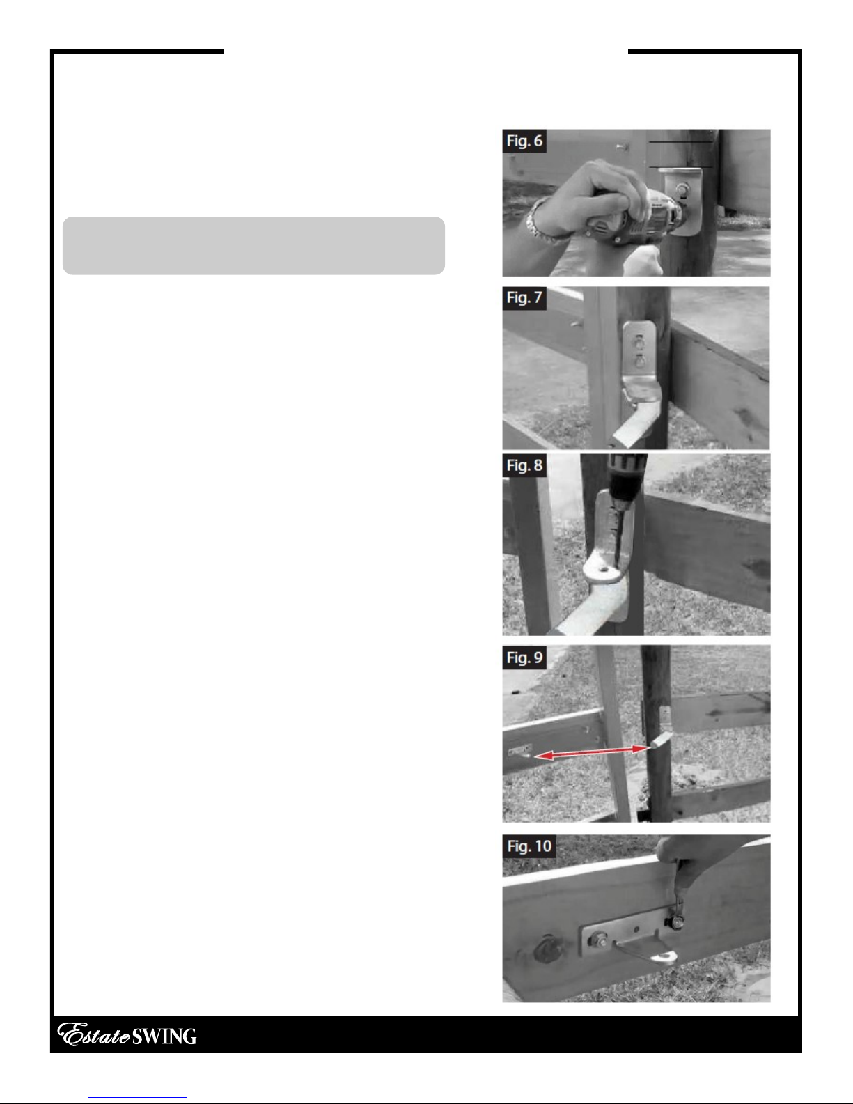
8. Place the lower “L” shaped bracket so the top
of the bracket is aligned with the bottom marking
on the post. Mark then drill and attach the bracket using 3/8” carriage bolts. [See Fig.6]
Check “L” shaped bracket for levelness before
putting in the second bolt.
9. Place the upper “L” shaped bracket and the
boomerang bracket on the lower “L” shaped
bracket. Position the brackets in the setback that
is being used.
10. With the 3 brackets clamped together, mark
then drill the upper “L” shaped bracket in place
and attach it using 3/8” carriage bolts. [See Fig.
7]
11. Drill through the center hole of the “L” shaped
set to penetrate the boomerang bracket. Secure
with 3/8 bolt and nut. Double check the setback
on the boomerang bracket.
12. Drill the set hole through all 3 brackets using a
5/16” drill bit in an area behind the first hole. Secure the hole with a 5/16” bolt and the provided
nuts and lock washers. [See Fig. 8]
13. WITH THE GATE IN THE OPEN POSITION meas-
ure 38” from the center of the hole on the boom-
erang bracket to the center of the hole on the
gate bracket - this should be the position of the
gate bracket on the open gate. [See Fig. 9]
14. Additionally measure and mark the gate
mounting bracket so that it is vertically centered
on the horizontal bar.
15. To ensure that the gate mounting bracket is
leveled, secure one side of the bracket, check
for levelness, and secure the other side with provided carriage bolts, nuts, and washers. [See Fig.
10]
E-S 300 / 302 Classic Series Instruction Manual
2.9
Page 21

SECTION 3:
Gate Operator Mounting,
Wiring Motors & Power
E-S 300 / 302 Classic Series Instruction Manual
Page 22

Page 23

Mounting Gate Operator (s)
1) Slide the rear of the gate operator
into the boomerang bracket. Next,
secure the operator onto the bracket with a connector pin.
2) Utilize the C-clip pliers in order to
attach a C-clip on the bottom side
of the connector pin.
3) Move the gate towards the operator arm and slide the front of the
operator onto the gate bracket.
4) Secure the front side of the
gate operator with a connector
pin, followed by a C-clip.
E-S 300 / 302 Classic Series Instruction Manual
3.1
Page 24

Check Usage of Stroke
1) Manually unlock the gate operator.
2) Physically swing the gate operator so
that it is almost fully extended in the
closed position, but not bottoming out.
3) Swing the arm back to its open position so that it is almost fully retracted,
but not bottoming out.
For the Push to Open Operation follow the directions shown above, except reverse
the position of the gate.
If not using all of the stroke length, please re-check setback. Not using the
full stroke length of the gate operator, the gate will have limited leverage.
E-S 300 / 302 Classic Series Instruction Manual
3.2
Page 25

Control Box & Running Wires
Control Box Mounting:
• The control box can be mounted on a post or
fence line.
• If you have a dual operator set up, make sure it is lo-
cated within 45’ of the slave motor.
• Allow at least 3 feet of clearance off the ground.
Wiring:
• Cut to fit the proper water tight connector ring for
your wire(s).
• Fill in any visible gaps with caulk.
Dual Operation Junction Box:
You will need the following items for this installation:
• Second Junction Box
• Screws
• PVC Conduit
1) Set aside the junction box cover and screws.
2) Drill two holes in the bottom of the junction box large
enough to fit the cables.
3) Mount the junction box within 5 feet of slave
operator.
The junction box can be mounted on a post or a fence
line. Allow at least 3 feet of clearance off the ground.
4) Insert operator cable and extension cable into the
holes in the bottom of the junction box, and seal with
caulk.
*You may also use a watertight connector and connector nut to secure the cables. Found at your local
hardware store.
6) Insert wires from extension cable and operator cable
into the terminal block connector as seen to the right.
7) The terminal block may be kept loose or
fastened inside of the junction box.
8) Install and secure cover.
See next page for instructions on running wire
under the driveway.
Mounting hole
TIP: If junction box is located in a
high moisture area, apply petroleum jelly on to the terminal block to
protect from moisture.
Mounting hole
Seal area accordingly
E-S 300 / 302 Classic Series Instruction Manual
3.3
Page 26

Easy Wiring Under Driveway
This portion of the manual will explain how to create
an easy conduit for the wires for dual gates.
This is what you would need to get started:
- Narrow shovel.
- ¾’ water pipe no more that 5’ in length (you would
need a total number of pipes that would equal your
driveway width plus 1’)
- ¾’ electric rigid pipe couplings (one for each joint in
the water pipe)
- 1 ¾’ “Tee”
- 1 ¾’ Plug.
- 1 ¾’ male galvanized pipe X female hose fitting
(usually in Brass)
- Large hammer.
All the above items could be found in a local
home supply store.
Dig a trench perpendicular to the driveway approximately 6 to 8 inches deep and 6’ long.
Hook up a typical garden hose assembled to
the first length of pipe as shown.
Turn on water and push the pipe under the
driveway, matching the pitch of the driveway. If
you hit a rock use the hammer to force the pipe
past the rock.
Attach additional pieces of pipe to the initial
length by removing the tee and using the coupling to add the additional length of pipe, reassemble the tee and repeat the above steps until
only 6 inches of pipe is sticking out from under
the driveway. On the opposite side of the driveway look for a wet spot or water bubbling up,
dig to find the end of the pipe.
E-S 300 / 302 Classic Series Instruction Manual
3.4
Page 27
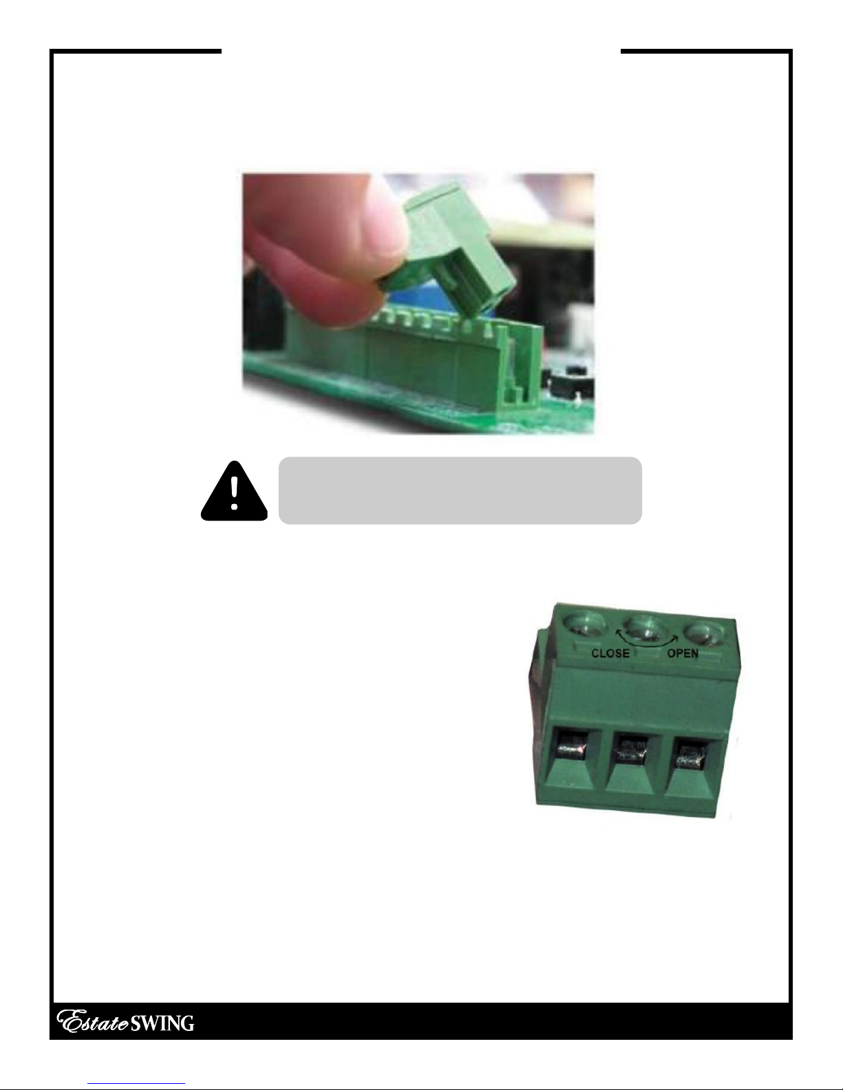
For Your Convenience
The green terminal strips on the control board are easily removed for wiring. Simply pull
straight out on the terminal strip to remove it from the board. It will slide right off. Slide it
back on when you are finished with your wiring connections.
Be sure you are placing your wires in the
terminal block correctly.
Take the terminal block off of the control board
to insert wires. Hold with screw terminals facing
upward.
Turn the screw counter-clockwise to open the
terminal and clockwise to close the terminal.
The terminals come closed. Be sure not to mistake this for open and insert the wires below the
terminal clamp. This will lack the conductivity to
complete the circuit.
E-S 300 / 302 Classic Series Instruction Manual
3.5
Page 28
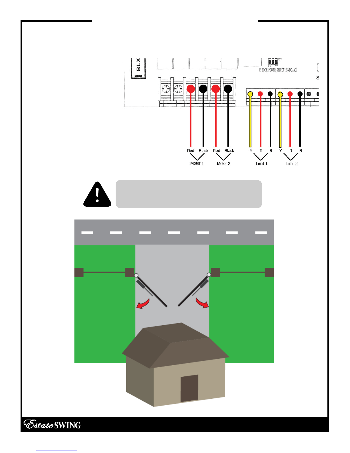
Wiring the Operator Arm (s)
For a dual gate, use the provided wire to connect the secondary motor to the
control board
Pull to Open
(Opening in towards
property)
It is important to choose the correct
operation type
E-S 300 / 302 Classic Series Instruction Manual
3.6
Page 29

Wiring the Operator Arm (s)
For a dual gate, use the provided wire to connect the secondary motor to the
control board.
Push to Open
(Opening out towards
the street)
It is important to choose the correct
operation type
E-S 300 / 302 Classic Series Instruction Manual
3.7
Page 30

Temporary Safety Jumpers & Dip Switch Settings
If you are not using a safety device
like a photo eye or safety loop the
Photocell terminal must remain
jumped to the GND terminal.
Dip Switches—To change any dip switches, you must turn the power
off before changing the setting.
Photo jumped to GND
ON: Auto-close on (the gate will
1.
re-close from the open position
after a time set in the programming section)
OFF: Auto-Close off
ON: Dual gate opener (2 motors)
2.
OFF: Single gate opener (1 motor)
IMPORTANT: We recommend before turning the gate opener
on for the first time to have dip switch 1 OFF. If the dip switch is
set to on, the gate will auto-reclose after turning it on without
any intentional activation on your part.
E-S 300 / 302 Classic Series Instruction Manual
3.8
Page 31

Power
The Estate Swing E-S 300 comes with 1) 24V transformer. The transformer supplied has
2 screw terminals to connect to. You may locate the transformer up to 200’ away
from the control board using 16 gauge, 2 conductor stranded direct burial low voltage wire. Do not use solid core wire.
Allow a minimum of 4’ of wire between the transformer and the control board.
Insert the two wires from the transformer into the two TRAN terminals on the control
board. The wires are not polarized, there is no positive or negative. Do NOT SPLICE THE
POWER CABLE WIRE.
Never run 110VAC power directly to the Estate Swing.
This will destroy the Estate Swing control board. Never connect the
power wire with the transformer plugged in. Contact between the
two lead wires, even for a second, will destroy the transformer.
Transformers are only warranted if the internal fuse is not blown. If
the fuse is blown an outside factor (shorting, surge, water, etc) has
caused the transformer not to function.
Plug the transformer into a 110 V AC outlet.
The transformer is not weather proof and must be kept in a covered area. Plug covers
are available from your dealer, contact 1-800-640-GATE for a dealer in your area.
Two 12V DC batteries (Max 5 a/h per battery) may be run in series as backup to the
24V transformer power. Running two 12V batteries in series creates a 24V system, you
cannot run them in parallel (see diagram above)
When you install new batteries - manually open the gate and allow the batteries to
charge for 12 hours through the system before using the gate opener.
E-S 300 / 302 Classic Series Instruction Manual
3.9
Page 32

SECTION 4:
Start Up and Operation
E-S 300 / 302 Classic Series Instruction Manual
Page 33

Page 34
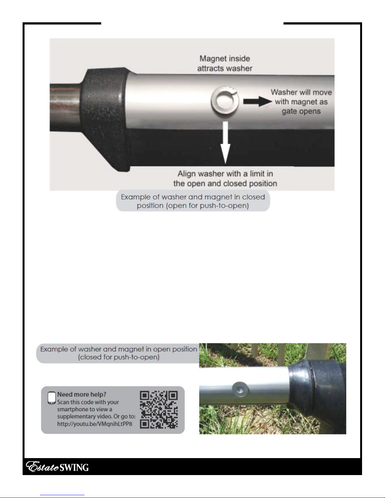
Find Limit Positions
1. Manually release the gate and move the gate to the desired closed position.
2. Take a metal washer and drag it along the side of the grey shaft until it is attracted
by the internal magnet.
3. Move the limit switch on the bottom to line up with the washer. Underneath the arm
there are slides secured with Philip head screws. After loosening the screws the switches will be able to slide. (picture of limits on page 4.3)
4. Move the gate to the open position and repeat with the open limit switch (as you
open the gate you can leave the washer on the side and it will move along with the
magnet).
E-S 300 / 302 Classic Series Instruction Manual
4.1
Page 35

First Run
This is our recommended procedure to run the gate for the first time.
PUSH 1 or PUSH 2 to increase or decrease the parameter. Then press SET button to
move to the next parameter.
1. Press SET button to begin.
2. LED shows P1: Press Push 1 to get P1 setting to 30.
3. Press SET button.
4. LED shows P2: Press Push 1 to get P2 setting to 10.
5. Press SET button.
6. LED shows P3: Press Push 1 to get P3 setting to 30.
7. Press SET button.
8. LED shows P4: Press Push 1 to get P4 setting to 3.
9. Press SET button.
10. LED shows P5: Press Push 1 to get P5 setting to 10.
11. Press SET button.
12. LED shows P6: Press Push 1 to get P6 setting to 2.
13. Press SET to finish. You should hear 3 beeps; this indicates parameter programming
is finished.
E-S 300 / 302 Classic Series Instruction Manual
Manually unlock the gate, then move it half-way and
re-engage. Activate using Push 1 button (as shown
above) The gate should run open. Press Push 1 again
and it should run closed. The gate is now set up for
regular usage.
4.2
Page 36
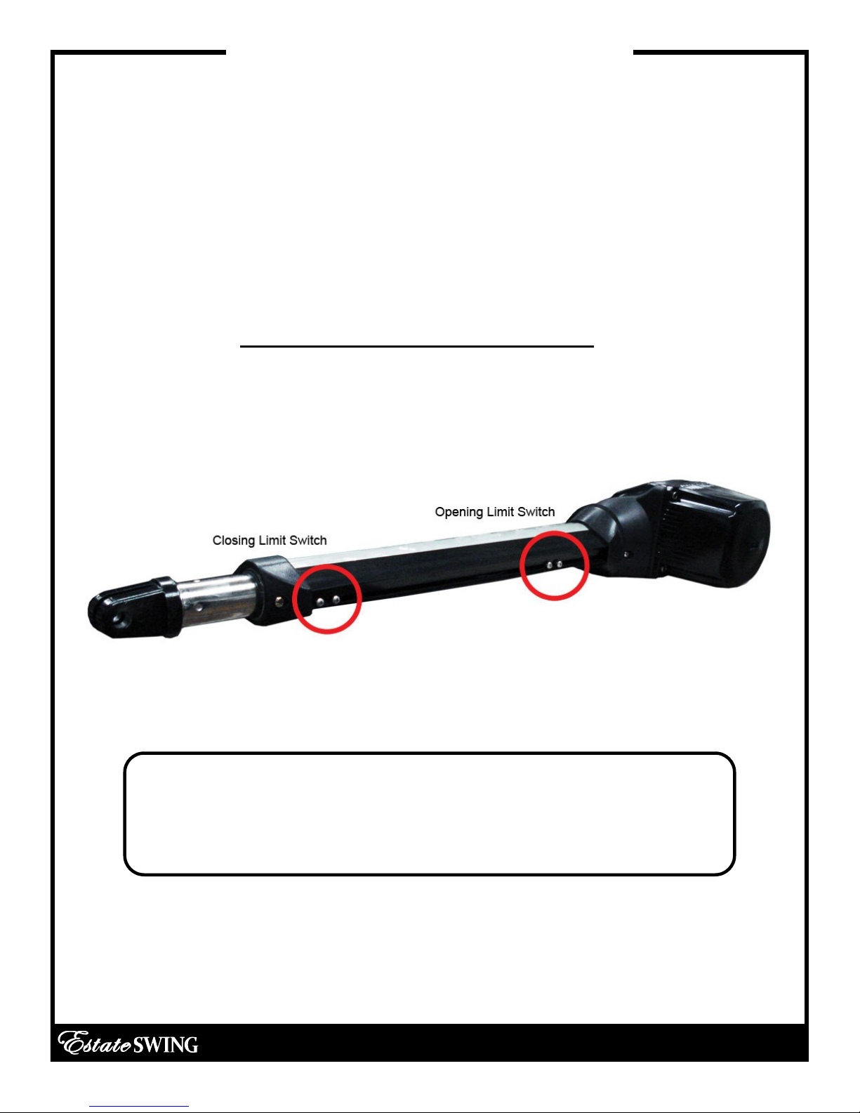
Determine Run Time
Once you complete the first run, press the button and actuate your gate a
few times. When the gate stops on the limits: If the gate has stopped short
of or further than desired position, adjust the limit switches:
After you have your limits in the correct position secure the position of the
switches with the screws and run your gate through a few cycles. On the
display you will see a count while the arms are moving. This is your run time.
Record your run time below.
Actual Run Time:
NOTE: The above example is for Pull-To-Open operation. If
you are installing your gate opener as Push-To-Open then the
open limit will be reverse of the above
E-S 300 / 302 Classic Series Instruction Manual
4.3
Page 37
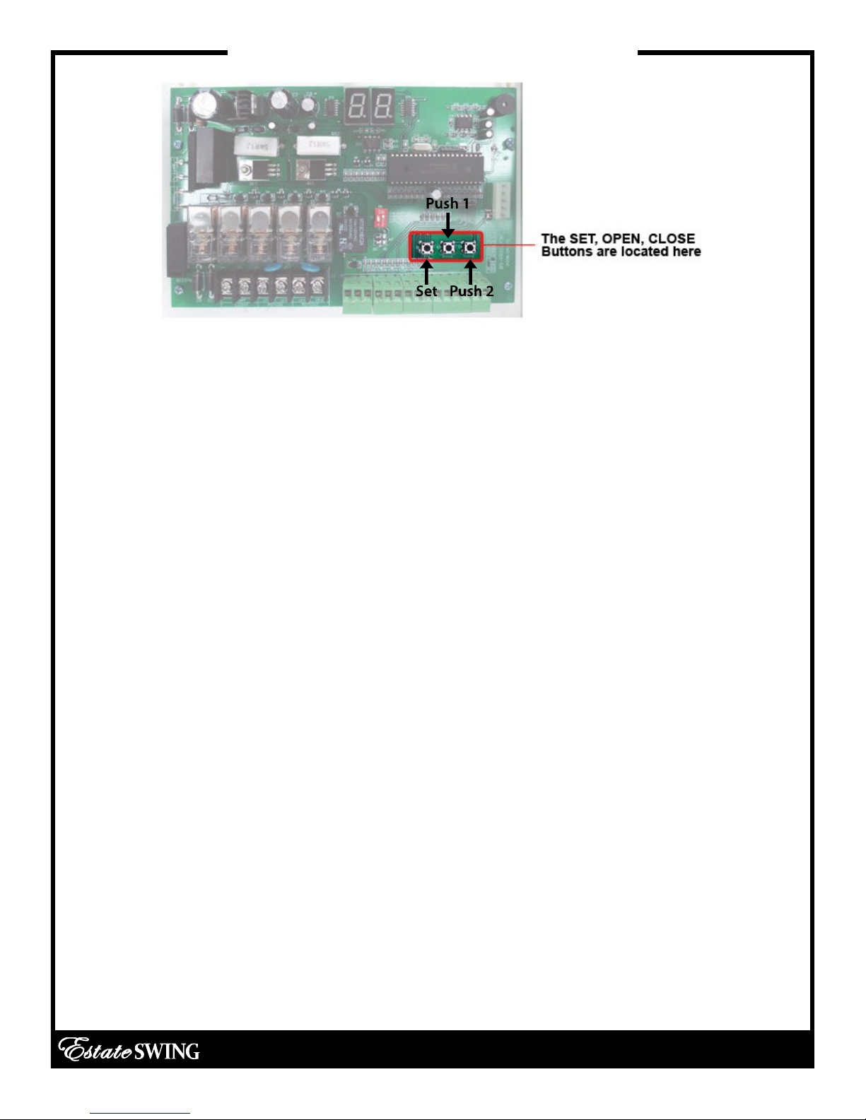
Operating Parameters Customization
1. LED shows P1: P1 is for setting your run time. The run time will be determined from the
time you had determined during the set up of the limit switches. Take that determined
run time and add 1 second. So if it takes 10 seconds to get from closed to open between limit switches; set the run time to 11 seconds. The options are 0-99 seconds.
2. LED shows P2: P2 is for setting your slow down time. The gate opener will slow down
to half speed after the time set on P2 expires. If you wish to have the gate open and
close faster make the slow down start time a longer period of time. If you want to put
less stress on the gears and gate set the slow time shorter to slow the momentum sooner. The options will adjust to match the previously set run time. NOTE: motor must be in
slow down to detect limits—be sure this number does not exceed the time the motor
take to move from one limit to the other.
3. LED shows P3: P3 is the force setting, the lower the number the easier the gate will reverse directions when it meets resistance. This number may have to be changed to a
higher setting if your gate is obstructing unexpectedly. The number should be set to the
highest number during initial setup and reduced to the point of reliable operation that
takes into account change in gate resistance through out the year. The options are 0-
32.
4. LED shows P4: P4 is for setting a delay between leafs if you have overlapping gates or
a gate lock. The motor wired into the master terminals (1) opens first if there is a delay
and closes second. It is recommended to have a delay of 3 seconds to avoid any jamming issues between leafs.
5. LED shows P5: P5 is the delay for automatic re-close from the open position – this option needs to be turned on using the dip switch on the board. The options are 0-99 seconds.
6. LED shows P6: P6 is the release for the gate lock – this option determines the length of
time 24VDC will be sent out of terminals E_LOCK. The options are 1-4 seconds.
E-S 300 / 302 Classic Series Instruction Manual
4.4
Page 38

Estate Swing 433 Plug-in Receiver
1. With the red plug already inside the control box, run the
grey receiver wire out of the box through one of the
water tight connections. DO NOT PERFORM THIS
STEP WITH THE RED PLUG ATTACHED TO THE
CONTROL BOARD.
2. Find a location for the receiver box on the gate post or a
fence post that is within the length of the receiver wire.
3. Using a #6 screw attached the top of the receiver to the
post. If you are happy with this position use the small
provided set screw in the bottom hole to secure the
receiver in place.
4. Attach the receiver wire to the terminals as seen below.
Please note that you will find a factory installed jumper
wire connected on the receiver. Leave this jumper wire
in place. One of the terminals that has the jumper wire
will have the 2nd from the bottom added to the terminal.
1st from the
bottom = V+
2nd from the
bottom = CH1
right (shaped
with jumper)
3rd from the
bottom = CH1
left
5.3
Page 39

Estate Swing 433 Plug-in Receiver (cont.)
5. Plug the red clip inside the control box into the
control board. The groove in the red clips should
snap into the guide on the 5 prong connector.
6. The red power light should come on the receiver.
7. Program your remotes to the receiver:
A. Press and release the LEARN1 button at the
top of the receiver board (ex 1). The learn LED
will illuminate steady (ex 2). (Fig 1)
B. Press and hold the button on the remote you
wish to program to the receiver.
C. Hold the remote button until the Learn LED
flashes and then turns off. (caution your gate
opener may be triggered during this process)
D. Repeat A through C for all additional remotes.
Fig. 1
NOTES ABOUT REMOTES:
You can program up to 400 codes into the receiver. This could mean 1 button on 400
different remotes or this could mean all 4 buttons on 100 remotes or anything in between.
Some choose to program all 4 buttons to a single receiver if they are not using multiple
gates to eliminate pressing the incorrect button on the remote. To do so follow the programming above with each button of the remote. You can erase all programmed codes
by holding Learn 1 until the Learn LED comes ON and then turns OFF.
8. Put the cover on the receiver and secure it in place using the provided screw.
IMPORTANT: The receiver is a drip proof receiver . This means that it is
designed to prevent water from accessing the inside of the receiver when the water
is moving downward with gravity (rain for example).
DO NOT mount the receiver anyplace that water may access it fr om another
angle. For example: Do not mount near sprinklers. Do not mount the receiver
horizontally. Do not mount the receiver near a flat surface where water could
splash upwards.
5.4
Page 40

SECTION 5:
Maintenance, Troubleshooting &
Accessories
E-S 300 / 302 Classic Series Instruction Manual
Page 41

Page 42
Maintenance
1) Lubricate the rear pivot and front pivot of the bracket.
2) Lubricate the gate hinges about every 3 months, and also
check for levelness of gate.
Rear Pivot
Front Pivot
E-S 300 / 302 Classic Series Instruction Manual
5.1
Page 43

Troubleshooting
If the gate opener will not move but the board is counting the run time:
• Check wiring connections.
• Be sure the arms are locked and not in manual operation.
• If not using slave limit switches, be sure jumpers are in place.
• Check the left hand fuse near the power supply—the proper way to inspect a fuse is to re-
move it from its clips and check for continuity.
If the gate opener moves a few inches or feet and stops or reverses directions:
• Increase the force setting (P3).
• Check the setback. The setback of the operator is important to correct operation due to
leverage the arm will have on the gate.
• Check the battery voltage. Proper voltage should be between 13.4 – 13.8 and drop no
more than a quarter of a volt under load.
• Disconnect accessories that may be triggering the gate a second time. The most frequent
issues are from exit sensors or other automatic opening devices.
The gate does not reach the desired stop points:
• Adjust the limit switches.
• Lengthen the run time parameter (P1).
• Check setback— if setback is incorrect it will limit how far the gate will move per inch of
stroke length.
If the gate will open but will not close:
• Manually move the gate slightly off the open position and then trigger the gate to go
closed. If the gate then moves closed the limits are most likely wired backwards. (Meaning the
open limit is wired to closed and closed wired to open)
• If you are not using safety devices the safety jumpers are in place. If PH is on display it is an
issue with the safety jumper or a device in the safety terminals.
• If you are using a safety device:
- Check to make sure you are using the normally closed connection instead of the normally
open.
- Check to be sure there is continuity being provided between the common and normally
closed wire of the safety device. If there is not continuity then refer to the installation guide of
the device to set up properly.
The display of the board will not light up:
• Check the power supply for 24VAC.
The arms are not wired in or properly wired on the limit switch connections. Without the limit
switch connections being closed the board will not light up.
More on next page
E-S 300 / 302 Classic Series Instruction Manual
5.2
Page 44

Troubleshooting
The gate opener is not stopping on the limit switches:
• Remove all pre-installed jumpers from the limit switch terminals that have limits going to
them. The slave gate terminals come pre-jumped for single operation, if you are using a dual
system pay particular attention to this detail and remove the jumpers when you put your limit
switches in.
• The limits are wired incorrectly—be sure that you are following the correct wiring diagram for
pull to open or push to open.
• For dual gates check that the delay between leafs is 2 or above. If both limits are triggered
simultaneously there is a chance a limit could be missed.
One or both arms are not moving:
• Check to be sure wiring color pattern matches the installation (Example: push to open wiring
for a push to open installation) - If the limits or motor are wiring opposite the installation the
board will believe it is closed or open when it is actually the opposite and the arms will never
move.
• Check the limit wires are correctly in the terminal blocks. The terminal blocks come with the
terminal clamps closed - however when the terminal clamps are closed there is a small space
below them one could mistake as place to insert a wire. If this is done then conductivity of the
connection will never be reached.
• Push or pull on the gate - if it moves the gears are disengaged and the gate is in manual re-
lease mode.
General fix for user to understand operation:
- Unlock the gate opener arm and move it to the half way position. Change the run time to a
low number (example: 2). Run the operator repeatedly.
- The operator should run one direction for a 2 count and then the other for a 2 count. After
you feel you have it following the run time correctly and swinging level and easily, then start
incrementally lengthening the run time.
- Eventually the run time will allow the operator arm to reach both limit switches and your setup is complete.
Dual gate - Only one arm moves:
• Check your dual settings - if the dip switch is changed to dual with the power on the setting
will not take effect, turn the power off and then back on to have the dual dip switch take effect. NOTE: If one leaf of a dual gate ever reaches its end limit before the other leaf starts
moving, the leaf that hasn’t started moving will not begin: correct this by cycling the gates
again and let it travel the full stroke or decrease the delay between leafs. The options are 0-9
seconds delay.
E-S 300 / 302 Classic Series Instruction Manual
5.3
Page 45

Troubleshooting
If you call in for technical support or warranty
support: Before any control board or motor will
be permitted to be sent in for testing or warranty you will be required to e-mail digital photos
to the technician.
This is done in your best interest to save unnecessary shipping expenses and time lost.
Many times we can come up with solutions to issues by seeing pictures that relay information that is impossible to relay through a phone conversation.
Below are examples of control board pictures and motor pictures that we will be looking for:
Pictures shown are actual customer photos
E-S 300 / 302 Classic Series Instruction Manual
5.4
Page 46

Control Board Overview
CAUTION! Do not run 110V AC power direct to the board. This
will cause permanent damage to both boards and void your
warranty. Caution!
Gate Opener reactions to signals:
PUSH1 and Receiver (PUSH 1 terminal, PUSH 1 button, 5 Prong Receiver):
Details:
• Will activate gate with momentary contact (momentary contact between PUSH1
and V+) or if you momentarily press the PUSH1 button.
• Controls both leaves in 2 leaf mode (Dip switch 2 in the ON position).
• Acts as party mode control to suspend auto-reclose by activating while counting
down auto-reclose in the open position.
Operational Sequence for terminal with auto-close ON (Dip switch 1 in on position):
1. In closed position - momentary contact will open gates.
2. When opening - momentary contact will stop gates and then it will auto reclose.
3. When stopped mid cycle waiting auto reclose - momentary contact will move the
gate in the direction opposite what it was moving before stopped.
4. When open and counting auto-reclose pause time - momentary contact will stop
pause time.
5. Stopped in open position from override of auto-reclose from PUSH1 or Receiver momentary contact will reactivate pause time and close gate.
6. When closing - momentary contact will stop the gate and then it will auto reclose.
Operational Sequence for terminal with auto-close OFF (Dip switch 1 in off position):
1. In closed position - momentary contact will open gates.
2. When opening - momentary contact will stop gates.
3. When stopped mid cycle - momentary contact will move the gate in the direction
opposite what it was moving before stopped.
4. When open - momentary contact will close gates.
5. When closing - momentary contact will stop the gate.
6. When stopped mid cycle - momentary contact will open the gate.
7. When open with auto-reclose off - momentary contact will have no effect.
8. When closing - momentary contact will re-open the gate.
E-S 300 / 302 Classic Series Instruction Manual
5.5
Page 47

Control Board Overview
CAUTION! Do not run 110V AC power direct to the board. This
will cause permanent damage to both boards and void your
warranty. Caution!
Gate Opener reactions to signals:
PUSH2 (PUSH 2 terminal and PUSH 2 button):
Details:
• Will activate gate with momentary contact (momentary contact between PUSH2
and V+).
• Controls both leaves in 2 leaf mode (Dip switch 2 in the ON position)
• Only opens the gate, never closes it.
• Pause time is able to be re-set if this terminal is closed through a momentary con-
tact. Then the time will be reset, count down the pause time, and reclose.
• Ideal for exit wand or exit loop.
Operational Sequence for terminal with auto-close ON (Dip switch 1 in on position):
1. In closed position - momentary contact will open gates.
2. When opening - momentary contact will have no effect.
3. When stopped mid cycle from PUSH 1 or the Receiver - momentary contact will
open the gate.
4. When open with auto-reclose on - momentary contact will re-set pause time and
will start counting again after release of momentary contact.
5. When pause time countdown is stopped in open from a momentary contact of
PUSH 1 or the Receiver - momentary contact will have no effect.
6. When closing - momentary contact will re-open the gate.
Operational Sequence for terminal with auto-close OFF (Dip switch 1 in off position):
1. In closed position - momentary contact will open gates.
2. When opening - momentary contact will have no effect.
3. When stopped mid cycle - momentary contact will open the gate.
4. When open with auto-reclose off - momentary contact will have no effect.
5. When closing - momentary contact will re-open the gate.
PUSH 1 and PUSH 2 – these terminals can hold as many normally open connections as
needed, they will be wired in parallel. They are used for keypads, push buttons, uni-
versal receivers, etc.
E-S 300 / 302 Classic Series Instruction Manual
5.6
Page 48

Control Board Overview
Light:
Motor 1:
Motor 2:
Limit 1:
Limit 2:
Sends pulses of 24VDC only while gate is running, and whether it is open
or closed.
L1-1, L1-2 = 24VDC power to single motor or master motor
L2-1, L2-2 = 24VDC power to slave motor
OL1 = Open limit for single motor or master (normally closed)
V+ = Common for limits, +12VDC
CL1 = Closed limit for single motor (normally closed)
OL2 = Open limit for slave motor (normally closed)
V+ = Common for limits, +12VDC
CL2 = Closed limit for slave motor (normally closed)
Photocell:
Button:
E_Lock:
V+ = +12VDC, Max 100 milliamps for photocell power
Photo = Input for safety eye photo beam connection (normally closed)
GND = Ground for photocell power/ground for photo connection
PUSH 1 = Ground for Push 1 Accessory
V+ = Positive voltage +12VDC for Push 1 accessory (relay only, not main
power)
*PUSH 1 / V+ is for push buttons, keypads, receivers, or any other dry
and momentary contact.
PUSH 2 = Ground for Push 2 accessory
V+ = Positive voltage +12VDC for Push 2 accessory (relay only, not main
power)
*PUSH 2 / V+ is for exit wand, exit loops or other open only dry contact
and momentary contact
Solenoid lock output - 12VDC (4 Amp max)
A = Positive B = Negative
Fuses:
F1 = 8A 250V, protects incoming power to board
E-S 300 / 302 Classic Series Instruction Manual
5.7
Page 49
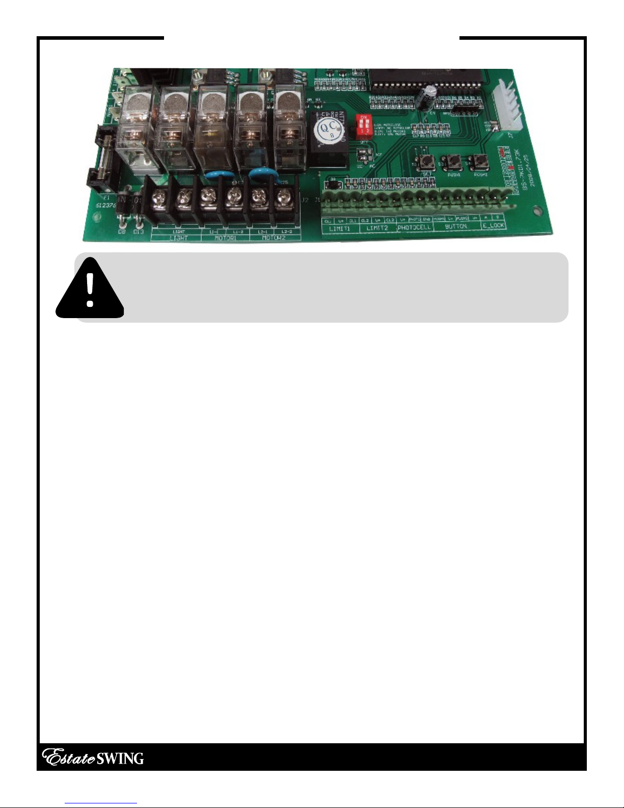
Control Board Overview
CAUTION! Do not run 110V AC power direct to the board. This
will cause permanent damage to both boards and void your
warranty. Caution!
Display Indicators:
Buzzer / Obstructions:
Lights off on board & stand by / normal operation
Lower right hand “dots” flashing normal pace:
Active / Awaiting command
EL: Sending voltage to EL terminals (electric lock)
OP: Opening cycle
AU: Auto-reclose countdown
CL: Closing cycle
If the gate(s) come in contact with an obstruction the
gate(s) will reverse direction for 2 seconds and stop to
allow the obstacle to be cleared from the gate path.
If the gate(s) obstructs 3 times in a row the gate(s) will
go into a hard shutdown mode and a buzzer alarm will
sound. At this point no accessories or remotes will be
able to activate the gate opener until the gate opener
is reset by disconnecting primary power battery.
E-S 300 / 302 Classic Series Instruction Manual
5.8
Page 50

Accessories Wiring
The manufacturer instructions that come with your accessory should have markings for wires or
terminals to connect to the gate opener. Please look for terminals named below in the instructions for the accessory.
Keypads, Receivers:
Normally Open (NO) or Input (INP) or Relay of entry device = V+ terminal (to right of PUSH1) of
PUSH block on gate opener control board.
Common (COM) or Ground (GND) or Relay of entry device = PUSH1 terminal of PUSH block on
gate opener control board.
NOTE: If the power for the accessory shares a Ground wire/terminal with the relay – Do Not pow-
er that accessory off this control board (example: WKP-P keypad). Instead power that device
with batteries.
12V Power positive (+) or (12V) or (PWR) of entry device = V+ terminal of PHOTO block on gate
opener control board.
12V Power Negative (-) or (GND) or (PWR) of entry device = GND terminal of PHOTO block on
gate opener control board.
*12V is not a misprint, the V+ terminal has a 12V output.
Push Button, Intercoms:
Normally Open (NO) or Input (INP) or Relay of entry device = V+ terminal (to right of PUSH1) of
PUSH block on gate opener control board.
Common (COM) or Ground (GND) or Relay of entry device = PUSH1 terminal of PUSH block on
gate opener control board.
Push buttons do not require power and Intercoms draw too much power to power from the
gate opener.
Exit Wand/Sensor, Exit Loop Detector, Exit Device:
Normally Open (NO) or Input (INP) or Relay of exit device = V+ terminal (to right of PUSH2) of
PUSH block on gate opener control board.
Common (COM) or Ground (GND) or Relay of exit device = PUSH2 terminal of PUSH block on
gate opener control board.
12V Power positive (+) or (12V) or (PWR) of exit device = V+ terminal of PHOTO block on gate
opener control board.
12V Power Negative (-) or (GND) or (PWR) or Shield wire of exit device = GND terminal of PHOTO
block on gate opener control board.
*12V is not a misprint, the V+ terminal has a 12V output.
E-S 300 / 302 Classic Series Instruction Manual
5.9
Page 51

Accessories Wiring
Photo Eye, Safety Edge, Safety Loop:
Normally Closed (NC) of safety device = Photo terminal of PHOTO block on gate opener control
board.
Common (COM) or Ground (GND) of safety device = GND terminal of PHOTO block on gate
opener control board.
12V Power positive (+) or (12V) or (PWR) of safety device = V+ terminal of PHOTO block on gate
opener control board.
12V Power Negative (-) or (GND) or (PWR) of safety device = GND terminal of PHOTO block on
gate opener control board.
*Remove safety jumper from PHOTO terminal if using a safety device.
*12V is not a misprint, the V+ terminal has a 12V output.
Solenoid Gate Lock:
Positive Lead of lock = A terminal of E_LOCK block on gate opener control board.
Negative Lead of lock = B terminal of E_LOCK block on gate opener control board.
Magnetic Gate Lock: Magnetic gate locks must have their own power supply and their own re-
lay.
Coil of relay for magnetic lock = A terminal of E_LOCK block on gate opener control board.
Coil of relay for magnetic lock = B terminal of E_LOCK block on gate opener control board.
Connect positive lead of the power supply directly to the positive lead of the mag lock.
Connect negative lead of the power supply to the N/C terminal of the relay.
Connect the COM terminal of the relay to the negative lead of the mag lock.
E-S 300 / 302 Classic Series Instruction Manual
5.10
 Loading...