

Estate Swing E-S 1600 Series, E-S 1602 Series, E-S 1600L Series, E-S 1602L Series Instruction Manual

Instruction Manual for the
E-S 1600/ E-S 1602 / E-S 1600L /
E-S 1602L Series

CE DECLARATION OF CONFORMITY OF MACHINES
(Directive 89/392/EEC, Annex II, Part B)
Manufacturer: FAAC S.p.A.
Address: Via Benini, 1 – 40069 Zola Predosa Bologna – Italy
Declares that: 409 A.K.A. Estate Swing (USA) mod operator
Is built to be integrated into a machine or to be assembled with other machinery to create a machine under the provisions
of Directive 89/392/EEC, and subsequent amendments 91/368/EEC, 93/44/EEC.
Conforms to the essential safety requirements of the following EEC directives:
Bologna, January 1, 2002
Managing Director
A. Bassi
o 73/23/EEC and subsequent amendment 93/68/EEC, 89/336/EEC and subsequent amendment 92/31/EEC and
93/68/EEC.
o And also declares the it is prohibited to put into service the machinery until the machine in which it will be
integrated or of which it will become a component has been identified and declared as conforming to the
conditions of Directive 89/392/EEC and subsequent amendments assimilated under national laws under DPR
#459 of July 24, 1996.
Warnings for the installer
General safety obligations
Abassi
1. Attention! To ensure the safety of people, it is important that you read all the following instructions. Incorrect installation or incorrect
use of the product could cause serious harm to people.
2. Carefully read the instructions before beginning to install the product.
3. Store these instructions for future reference.
4. This product was designed and built strictly for the use indicated in the documentation. Any other use, not expressly indicated here,
could compromise the good condition/operation of the product and/or be a source of danger.
5. FAAC declines all liability caused by improper use or use other than that for which automated system was intended.
6. Do not install the equipment in an explosive atmosphere; the presence of inflammable gas or fumes is a serious danger to safety.
7. The mechanical parts must conform to the provisions of Standards EN 12604 and EN 12605.
For non-EU countries, to obtain an adequate level of safety, the standards mentioned above must be observed, in addition to national
legal regulations.
8. FAAC is not responsible for failure to observe Good Technique in the construction of the closing elements to be motorized, of for any
deformation that may occur during use.
9. The installation must conform to Standards EN 12453 and EN 12445.
The safety level of the automated system must be C+D.
10. Before attempting any job on the system, cut out electrical power and disconnect the batteries.
11. The main power supply of the automated system must be fitted with an all-pole switch with contact opening distance of 3 mm or greater. Use of a 6A thermal breaker will all-pole circuit break is recommended.
12. Make sure that a differential switch with threshold of 0.03 A is fitted upstream of the system.
13. Make sure that the earthing system is perfectly constructed, and connect metal parts of the means of the closure to it.
14. The automated system is supplied with an intrinsic anti-crushing safety device consisting of a torque control. Nevertheless, its tripping
threshold must be checked as specified in the Standards indicated at point 10.
15. The safety devices (EN 12978 standard) protect any danger areas against mechanical movement risks, such as crushing, dragging, and
shearing.
16. Use of at least one indicator-light (e.g. FAACLIGHT 12VDC) is recommended for every system, as well as a warning sign adequately
secured to the frame structure, in addition to the devices mentioned at point “15”.
17. FAAC declines all liability as concerns safety and efficient operation of the automated system, is system components not produced by
FAAC are used.
18. For maintenance, strictly use original parts by FAAC.
19. Do not in any way modify the components of the automated system.
20. The installer shall supply all information concerning manual operation of the system in case of an emergency, and shall hand over to
the user the warnings handbook supplied with the product.
21. Do not allow children or adults to stay near the product while it is operating.
22. Keep remote controls or other pulse generators away from children, to prevent the automated system from being activated involuntarily.
23. Transit through the leaves is allowed only when the gate is fully open.
24. The user must not attempt any kind of repair or direct action whatever and contact qualified personnel only.
25. Do not short-circuit the poles of the batteries and do not try to recharge the batteries with power supply units other than Primary or
Secondary cards.
26. Do not throw exhausted batteries into containers for other waste but dispose them in the appropriate containers to enable them to be
recycled.
27. Anything not expressly specified in these instructions is not permitted.

Estate Swing Summary of Functions
The Estate Swing is only to be used for vehicular swing gates in a Class I
setting.
Class I: A vehicular gate opener (or system) intended for use in a home of
one-to-four single family dwelling, or a garage or parking area associated
therewith.
The FAAC Estate Swing automated system was designed and built for controlling
vehicle access. Do not use for any other purpose.
The external automation with an electro-mechanical non-reversing linear arm
automates residential swing-leaf gates with leaves of up to 16’ in length. It
consists of an irreversible electro-mechanical operator with built in opening and
closing limits and utilizes a worm screw system. The irreversible system ensures
the gate is mechanical locked when the motor is not operating. A lock still needs to
be installed if security or high winds are a concern. A manual release makes it
possible to move the gate in the event of a power-cut or fault.
Keep this manual safely stored after
installation.
Serial Number__________________________
Date of Purchase_______________________
Place of Purchase______________________
Have this information on hand while handling all
service and warranty issues.
This manual and its contents are produced by Web Direct Brands, Inc.

The table of contents are listed to assist you locating a desired section. We do howev-
er strongly suggest studying every page of the instruction manual before attempting
installation.
SECTION:
Review of specifications, warnings, and tools 1
Specifications of the Estate Swing and Components 1.1
Parts List 1.2
System Overview & Preliminary Checks 1.3
Tools Needed for Installation 1.4
Installation 2
Manual Operation, Restoring Automation 2.1
Table of Contents
READ FIRST: Determining Push or Pull to Open 2.2
IMPORTANT: Determining Setback—Pull to Open 2.3
Installation of Operator—Pull to Open 2.4-.7
IMPORTANT: Determining Setback—Push to Open 2.8
Installation of Operator—Push to Open 2.9-.12
Easy Wiring Under Driveway 2.13
For Your Convenience 2.14
Wiring, Jumpers and Receiver 3
Wiring Operator Arm(s) - Pull to Open 3.1-.3
Wiring Operator Arm(s) - Push to Open 3.4-.5
Temporary Safety Jumpers and Dip Switch Settings 3.6
Power 3.7
Limit Switches 4
Fine Tune Limit Switch - Pull to Open 4.1-.2
Fine Tuning Limit Switch - Push to Open 4.3

The table of contents are listed to assist you locating a desired section. We do howev-
er strongly suggest studying every page of the instruction manual before attempting
installation.
SECTION:
Diagnostics 5
First Run & Parameters 5.1-.2
Plug-in Receiver 5.3-.4
Table of Contents
Maintenance and Trouble Shooting
Bracket Maintenance 6.1
Troubleshooting 6.2-.5
Accessories 7
Control Board Overview 7.1-.4
Accessories 7.5-.6
Marks pages with opener or usage warnings. Although we have marked these as very
important warnings, please read the entire manual. Every step is impor tant to the
correct installation of your gate opener.

MODEL Estate Swing
Specifications
Power Supply
Rated Absorbed Power (W)
Current (A)
Travel (in.)
Cycles per hour
Operating Ambient Temp
Protection class
Gate leaf max length (ft.)
Gate leaf max weight (lbs.)
Operator overall dimensions LxHxD(in.)
Operator Weight
115V AC/ 24V AC
70
3
11
Continuous Duty / Aprox. 75
-4 to 131 F
IP44
Up to 14 (L-series: up to 20)
Up to 800 (L-series: up to 1000)
See below
18 lbs (L-series: 19 lbs)
E-S 1600L arm
E-S 1600 arm
1.1

Estate Swing Parts List
Primary or Single Operator
A. Control Box
B. Operator Arm with 6' of 5 Conductor Wire and
Key
C. Control Board
D. Transmitter
E. Receiver
F. Transformer
G. Gate Mounting Bracket
H. Post Mounting Brackets
I. Mounting Hardware
1 - 3/8”x1 1/2” Hex bolts, washer, nut
1 - 5/16”x1 1/2” Hex bolt, washer, nut
2 - 3/8”x2” Carriage bolt, washers, nut
1 - 1/4”x2” Hex bolt, washers, nut
Secondary Operator (If Applicable)
B
. Operator Arm with 33' (45')
of 5 Conductor Wire
G. Gate Mounting Bracket
H. Post Mounting Brackets
I. Mounting Hardware
1 - 3/8”x1 1/2” Hex bolts, washer,
nut 1 - 5/16”x1 1/2” Hex bolt,
washer, nut 2 - 3/8”x2” Carriage bolt,
washers, nut 1 - 1/4”x2” Hex bolt,
washers, nut
1.2

Standard System
Overview and Safety Zones
The system display to the below is a
recom-mended standard system. Other
approved accessories can be installed.
Photo sensors and a flashing light
indicating gate move-ment is
recommended for safety purposes.
1,2 Estate Swing Operator
3 Photocells (not included)
4 Control board
5 N/A
6 Push button opening device (not included)
7 Receiver extension (not included)
8 12Vdc flashing lamp (not included)
9 Positive stop
10 DC transformer
Notes:
1) When laying electrical cables, use appropriate rigid and/or
flexible tube.
2) Do not run any wires in the same conduit as 110 AC
power that may be in the area. This will cause unwanted
interference.
IMPORTANT
Preliminary Checks:
To ensure safety and an efficiently operating automated system, make sure the
following condi-tions are observed.
The gate and post must be suitable for being automated. Check that the structure is
sufficiently strong and rigid, and its dimensions and weights conform to those
indicated on page 1.
Make sure the leaves move smoothly without any irregular friction during entire travel.
Make sure the hinges are in good condition. Ball bearing hinges are ideal for gates
weighing over 200 lbs. or over 10’ in length.
Make sure the gate is plumb and level.
The fence post must be secured in the ground with concrete. This will
prevent alteration of alignments and leveling during installation and
during cycles.
1.3

Power Drill
Crescent Wrench
Tools Needed
Flat Head Screwdriver
Hacksaw
Phillips Head
Screwdriver
C-Ring Pliers
Tape Measure
Level
Wire Strippers
C-clamps
3/8”, 1/4”, 5/16” Drill Bits
Other items that may be needed prior to commencing installation. Bolded items are
necessary to all applications.
Start and stop post, bracket or door stop. Although the FAAC Estate swing 1600
features built in limit switches some may choose to use positive stops:
16, 14 or 12 gauge, 2 conductor stranded direct burial low voltage wire will be
required to run power to your operator. Length is deter mined by distance
between transfor mer power supply and the control box.
4 - 3/8” Bolts will be needed to connect the 2 “L” shaped brackets to the
post. Length will be determined by the size of your posts.
A metal support bracket may be needed to achieve the appropriate desired setback.
The metal support bracket will be bolted or welded to your post to give a larger
amount of space to mount the provided mounting bracket.
A voltage meter and digital camera will be necessary to run diagnostic checks.
If your transformer is going to be plugged into an outdoor outlet you will need to
weatherproof that outlet and transformer. Electrical boxes or plug covers can be
obtained from a local hardware store to accommodate both the plug and transformer.
Hardware to attach the control box to a post or fence.
Connectors for running wires into the control box.
Protect all ingoing and outgoing wires with a surge suppressor. Consult your local
dealer for more information.
1.4

Manual Operation Mode
1)
2) Remove rubber cover
3) Insert key and turn it 90 degrees.
4) Flip release lever up.
To exit manual mode, reverse the above steps.
2.1

The following section is instructions on
mounting your gate opener. Your gate can
be mounted one of two ways:
Pull-To-Open: With the gate opener on the inside of the
property, the gate will swing in towards the property. The
gate opener will be extended in the gate’s closed
position and as the opener retracts it PULLS the gate
open.
Instructions are pages 2.3 - 2.7
Push-To-Open: With the gate opener on the inside of the
property, the gate will swing out away from the property
towards the street. The gate opener will be
retracted in the gate’s closed position and as the opener
extends it PUSHES the gate open.
Instructions are pages 2.8 - 2.12
After deciding which method you will use
to automate your gate, make an X across
the pages of the installation method you
will not
This will prevent mistakenly using the wrong instructions
for your installation as the two sections look very similar.
be using.
2.2

IMPORTANT: Determining Correct Setback
PULL TO OPEN - Standard operation. This means the gate operator is
mounted on the inside of the property and pulls your gate in towards the property.
There are 4 factors to keep in mind when finding the setback mounting:
1) The (A) measurement is perpendicular from the gate in the CLOSED position.
2) There must be clearance for your gate opener to attach to the gate in the closed position.
This is most commonly an issue on columns. Re-positioning of the hinges or Push-To-Open
operation may be required to achieve clearance.
3) The brackets do not and must not move after installation.
4) The "L" shape brackets can be mounted anywhere on the post or column. They can be
mounted on a separate post or fence as well. The only factor of importance is that when
mounting of the brackets is done the hole in the boomerang bracket that the gate opener mounts
on matches the setback on this page.
It is best to C-Clamp brackets on and test arm movement clearance before permanently attaching
them.
A B
6” 6
5.5” 5.5”
”
a
90o
100o
To determine the position of the gate
mounting bracket (above is for the post
mounting bracket) re-fer to step 9 in the
section “Installation of operator”
2.3

Installation of Operator—Pull-to-Open
1. Find the proper set back for your operator (from
previous page). Do this by holding the bottom “L”
shaped bracket against the post. Marking its horizontal
positioning on the post using a vertical line up from the
middle of the bracket. Also mark your angled bracket
for positioning on the “L” shaped bracket. The hole on
the end of the angled bracket should be in the setback
position.
HINT: Trace the bracket on cardboard and use the
cardboard to make a template.
2. Cut off the excess
length (if any) of the
angled brack-et using a
hacksaw.
3. Position the angled
brack-et between the two
“L” shaped brackets in the
same position as when
the setback was found.
Clamp the 3 brackets
together. Drill through the
angled bracket using the
pre-drilled holes in the “L”
shaped brackets us-ing a
3/8” drill bit. Drill through
all three brackets using a
5/16” drill bit in a position
behind the first hole.
4. Insert a 3/8” x 1” bolt
in the center hole and a
5/16” bolt in the rear
hole. Secure them using
the provided nuts and
lock washers.
Before permanently attaching any brackets, be sure to test
arm motion and clearance.
For full capacity, the amount of stainless steel showing retracted shovel be
between 2 1/4 - 3 inches and 15 1/4 - 16 1/2 inches when extended (L-series: 20
- 21 1/4 inches when extracted).
2.4

5. Temporarily position the gate side
mounting bracket. (horizontal position
does not matter, vertical position on
the gate is the position you are
matching to the post bracket.) Position
your assembled gate mounting along
the
previouslydrawn vertical line and level the
angled piece with the horizontal piece of
the gate mounting bracket using a level.
Mark your holes, drill and attach the
brackets using (4) 3/8” carriage bolts.
6. Assemble the rear fitting to the operator as shown below
7. Run the 5 wires from the arm(s) to the control board as seen in section 3.
8. Set the operator for manual operation. And extend the operator arm to a near full
extended position.
2.5
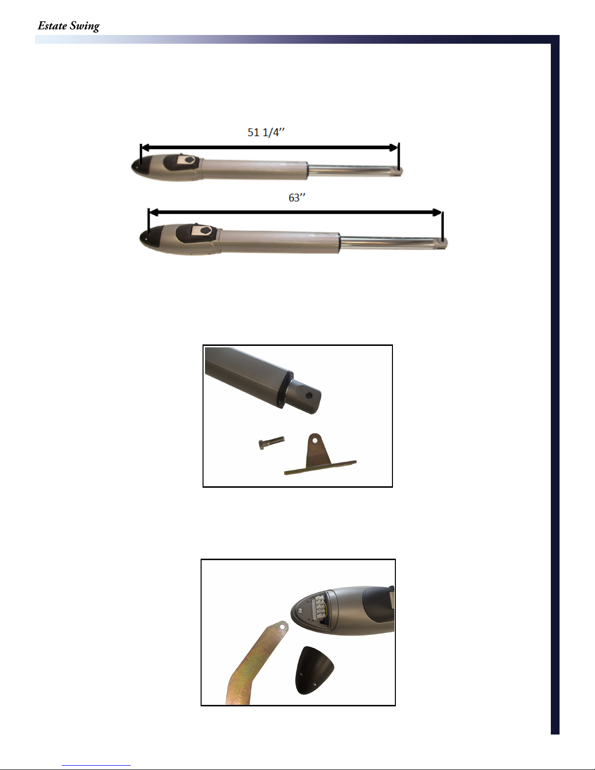
9. Extend the operator arm so the measurement between the center of the pivot hole
on the rear bracket and the center of the pivot hole in the front mounting measures 51
1/4 inches (63 inches for L-series). After finding the measurement relock your
operator arm.
E-S 1600 arm
E-S 1600L arm
This is your closed mounting position.
10. Assemble the front gate mounting bracket as shown below. (bottom ring can
be left off if security is not a concern)
11. Attach the operator to the post mounting bracket using the supplied pins as shown
below, support the arm to prevent dropping and breakage of the rear fitting. (bottom ring
can be left off if security is not a concern)
2.6

12. Close the gate leaf. With the operator attached on the post side, move the end of
the arm to the gate and, keeping the gate operator in a perfectly horizontal position,
determine the gate mounting position. The arm should already be in it’s full closed length
that was determined in step 9
13. Attach the gate mounting bracket
using carriage bolts, nuts, and washers.
14. Release the gate operator once
more.
Manually test the gate by completely
opening and closing it, checking for
smooth operation.
Gate in Closed position
2.7

IMPORTANT: Determining Correct Setback
PUSH TO OPEN - This operation is commonly used if you driveway slopes up
after the gate, preventing it from swinging in. This means the gate operator is
mounted on the inside of the property and pushes your gate out away from the
property.
There are 4 factors to keep in mind when finding the setback mounting:
1) The (A) measurement is perpendicular from the gate in the CLOSED position.
2) There must be clearance for your gate opener to attach to the gate in the closed position.
This is most commonly an issue on columns. Re-positioning of the hinges or Push-To-Open
operation may be re-quired to achieve clearance.
3) The brackets do not and must not move after installation.
4) The "L" shape brackets can be mounted anywhere on the post or column. They can be
mounted on a separate post or fence as well. The only factor of importance is that when
mounting of the brackets is done the hole in the boomerang bracket that the gate opener
mounts on matches the setback on this page.
It is best to C-Clamp brackets on and test arm movement clearance before permanently attaching
them.
To determine the position of the
gate mount-ing bracket (above is
for the post mounting bracket) refer
to step 9 in the section
“Installation of operator - PTO”
A B
6
”
5.5” 5.5”
6”
a
90o
100o
2.8

Installation of Operator—Push-to-Open
1. Find the proper set back for your
operator (from previous page). Do this by
holding the bottom “L” shaped bracket
against the post. Marking its horizontal
positioning on the post using a vertical line
up from the middle of the bracket. Also mark
your angled bracket for posi-tioning on the
“L” shaped bracket. The hole on the end of
the angled bracket should be in the setback
position.
HINT: Trace the bracket on cardboard
and use the cardboard to make a
template.
2. Cut off the excess
length (if any) of the
angled brack-et using a
hacksaw.
3. Position the angled
brack-et between the two
“L” shaped brackets in the
same position as when
the setback was found.
Clamp the 3 brackets
together. Drill through the
angled bracket using the
pre-drilled holes in the “L”
shaped brackets using a
3/8” drill bit. Drill through
all three brackets using a
5/16” drill bit in a position
behind the first hole.
4. Insert a 3/8” x 1” bolt
in the center hole and a
5/16” bolt in the rear
hole. Secure them using
the provided nuts and
lock washers.
Before permanently attaching any brackets, be sure to test arm
motion and clearance.
For full capacity, the amount of stainless steel showing retracted shovel be
between 2 1/4 - 3 inches and 15 1/4 - 16 1/2 inches when extended (L-series: 20
- 21 1/4 inches when extracted).
2.9

5. Temporarily position the gate side
mounting bracket. (horizontal
position does not matter, vertical
position on the gate is the position
you are matching to the post
bracket.) Position your assem-bled
gate mounting along the previously
drawn vertical line and level the angled
piece with the horizontal piece of the
gate mounting bracket using a level.
Mark your holes, drill and attach the
brackets using (4) 3/8” carriage bolts.
6. Assemble the rear fitting to the operator as shown below.
7. Run the five wires from the arm(s) to the control board as seen in section 3.
8. Set the operator for manual operation. And extend the operator arm slightly
past the full retracted position..
2.10

9. Retract the operator arm so the measurement between the center of the pivot hole
on the rear bracket and the center of the pivot hole in the front mounting measures 36
inches (41 inches for L-series). After finding the measurement relock your operator
arm.
E-S 1600L
E-S 1600
This is your closed mounting position.
10. Assemble the front gate mounting bracket as shown below. (bottom ring can be left
off if se-curity is not a concern)
11. Attach the operator to the post mounting bracket using the supplied pins as shown
below, support the arm to prevent dropping and breakage of the rear fitting. (bottom
ring can be left off if security is not a concern)
2.11

12. Close the gate leaf. With the
operator attached on the post side,
move the end of the arm to the gate
and, keeping the gate operator in a
perfectly horizontal position, determine
the gate mounting position. The arm
should already be in it’s full closed
length that was determined in step 9.
13. Attach the gate mounting bracket
us-ing carriage bolts, nuts, and
washers.
14. Release the gate operator once
more.
Manually test the gate by completely
opening and closing it, checking for
smooth operation.
Gate in Closed position
2.12

Easy Wiring Under Driveway
This portion of the manual will explain how to
create an easy conduit for the wires for dual gates.
This is what you would need to get started:
- Narrow shovel.
- ¾’ water pipe no more that 5’ in length (you would
need a total number of pipes that would equal your
driveway width plus 1’)
- ¾’ electric rigid pipe couplings (one for each joint in
the water pipe)
- 1 ¾’ “Tee”
- 1 ¾’ Plug.
- 1 ¾’ male galvanized pipe X female hose fitting
(usually in Brass)
- Large hammer.
All the above items could be found in a local
home supply store.
Dig a trench perpendicular to the driveway
approximately 8 to 12 inches deep and 6’ long.
Hook up a typical garden hose assembled to the first
length of pipe as shown.
Turn on water and push the pipe under the
driveway, matching the pitch of the driveway. If you
hit a rock use the hammer to force the pipe past the
rock.
Attach additional pieces of pipe to the initial
length by removing the tee and using the
coupling to add the additional length of pipe,
reassemble the tee and repeat the above steps until
only 6 inches of pipe is sticking out from under the
driveway. On the opposite side of the driveway look
for a wet spot or water bubbling up, dig to find the
end of the pipe.
2.13

For Your Convenience
The green terminal strips on the control board are easily removed for wiring. Simply pull straight
out on the terminal strip to remove it from the board. It will slide right off. Slide it back on
when you are finished with your wiring connections.
Be sure you are placing your wires in the
terminal block correctly.
Take the terminal block off of the control board to insert
wires. Hold with screw terminals facing upward.
Turn the screw counter-clockwise to open the terminal
and clockwise to close the terminal.
The terminals come closed. Be sure not to mistake this for
open and insert the wires below the terminal clamp. This
will lack the conductivity to complete the circuit.
2.14

Wiring the Operator Arm(s)
Attaching Arm Cover
1. Remove top cover.
2. Run the 5 Conductor wire through the cable gland and tighten the cable gland to
squeeze the wire. Attach wires as indicated using thicker wires for motor installation.
3. After attaching the wire according to the picture below and the chart on the following
page, cover the operator arm terminal board with the cover.
3.1

Wiring the Operator Arm(s)
For a dual gate, use the provided wire to connect the secondary motor to the control board
Pull to Open
(Opening in towards
property)
It is important to choose the correct
operation type
3.2

Wiring the Operator Arm(s) for Pull to Open
1. Locate the wiring terminal board on the bottom of the
operator arm(s).
2. Wire the operator arms according to the diagram below.
NOTE: 1 indicates primary arm or Single operator connections, 2 indicates
secondary arm if applicable and is not used in single gate installations.
Wiring Connections for Operator Arm Power.
Position from
right in arm
M-1 Red
M-2
Arm to Board
Wire Color
Lg. wire
Black
Lg. wire
Terminal Pur-
pose
Power
Power
Board Connection
Terminal
M1-1 (primary)
M2-1 (secondary - if
dual)
M1-2 (primary)
M2-2 (secondary - if
dual)
COM Red Limit
Common
Limit 1 COM -
primary Limit 2 COM
- secondary
CL
OL
NOTE: Ground Terminal Screw indicates right from left as seen in picture on previous
page, the ground terminal screw however is not used on this model.
Black Limit
Closed
Position
Yellow Limit
Open
Position
CL1 / Limit 1 (primary)
CL2 / Limit 2 (secondary - if
dual)
OL1 / Limit 1 (primary)
OL2 / Limit 2 (secondary - if
dual)
There is an Illustration to match the above chart on the
previous page.
Push-To-Open wiring is found on the next page.
We have recently changed provided wire colors. If your wire colors do not
match the chart above and you need help determining terminal placement,
call 1-800-640-GATE for assistance.
3.3

Wiring the Operator Arm(s)
For a dual gate, use the provided wire to connect the secondary motor to the control board.
Push to Open
(Opening out towards
the street)
It is important to choose the correct
operation type
3.4

Wiring the Operator Arm(s) for Push To Open
1. Locate the wiring terminal board on the bottom of the operator arm(s).
2. Wire the operator arms according to the diagram below.
Wiring Connections for Operator Arm Power.
Position
from
right in
arm
M-1 Red
Arm to board
Wire Color
Terminal
Purpose
Power CN2
Lg. Wire
M-2
Black
Power CN2
Lg. Wire
COM Red Limit
Common
CL
Black Limit
Open
Position
OL
Yellow Limit
Closed
Position
Board
Terminal
Block
CN3
CN3
CN3
Board Connection
Terminal
M1-2 (primary)
M2-2 (secondary - if
dual)
M1-1 (primary)
M2-1 (secondary - if
dual)
primary - Limit 1 COM
secondary - Limit 2 COM
OL1 - Limit 1 (primary) OL2
- Limit 2 (secondary - if dual)
CL1 - Limit 1 (primary) CL2
- Limit 2 (secondary - if dual)
NOTE: 1 indicates primary arm or Single operator connections, 2 indicates
secondary arm if applicable and is not used in single gate installations.
3.5

Temporary Safety Jumpers and Dip Switch Settings
If you are not using a safety device like a
photo eye or safety loop the Photocell
terminal must re-main jumped to the GND
terminal.
Dip Switches—To change any dip switches, you must turn the power
off before changing the setting.
ON: Auto-close on (the gate will re-close from
1.
the open position after a time set in the
programming sec-tion)
OFF: Auto-Close off
Photo jumped to GND
2.
3.
ON: Dual gate opener (2 motors)
OFF: Single gate opener (1 motor)
ON: Electric Lock being used
OFF: Electric Lock not used
IMPORTANT: We recommend before turning the gate opener on for
the first time to have dip switch 1 OFF. If the dip switch is set to on,
the gate will auto-reclose after turning it on without any intentional
activation on your part.
3.6

Power
The Estate Swing E-S 500 comes with 1) 24V transformer. The transformer supplied has 2
screw terminals to connect to. You may locate the transformer up to 200’ away from the
control board using 16 gauge, 2 conductor stranded direct burial low voltage wire. Do not
use solid core wire.
Allow a minimum
of 4’ of wire
between the
transformer and
the control
board.
Connect the wire (not provided) from the transformer to the provided crimp on spade
connectors and connect to the control board marked TRAN. There is no polarity.
Never run 110VAC power directly to the Estate Swing.
This will destroy the Estate Swing control board. Never
plug in the transformer when the wires are not connected
to the board. Contact between the two lead wires will
destroy the transformer.
Plug the transformer into a 110 V AC outlet.
The transformer is not weather proof and must be kept in a covered area. Plug covers are
available from home stores.
Two 12V DC batteries (min 5 a/h per battery) may be run in series as backup to the 24V
transformer power.
When you install new batteries - manually open the gate and allow the batteries to charge
for 24 hours through the system before using the gate opener.
3.7

Fine Tuning Limit Switches - Pull-to-Open
Understanding the limit switches
The stroke length is the distance between both limit switches. Increasing the stroke length will make your operator open further or
close further.
Decreasing the stroke length will make your operator open less or
close less.
The limit switches are for fine adjustment only. Full stroke length
should be used for maximum capacity.
Continue to the next page for limit adjustment
directions.
4.1

Programming Limit Switches - Pull-to-Open
1.Temporarily install gate opener arm upside down.
2.Press and hold the SET button until PL shows on the display (about 3 seconds)
3.Press and release BUTTTON1 and the display will change to O1 (Open limit, Motor 1)
4.Manually release the gate (motor 1 gate for dual gate opener) and move the gate to the
desired open position.
5.Loosen the screws and adjust the limit switch that is closest to the motor until you hear an
audible BEEPING from the board. When the switch is in position the beeping will continue to
sound as long as O1 is on display. Snugg down the screws so the limit switch will not move.
6.Press and release BUTTON1 and the display will change to C1 (Closed limit, Motor 1)
7.Manually move the gate to the desired closed position.
8.Loosen the screws and adjust the limit switch that is furthest from to the motor until you hear
an audible BEEPING from the board. Snugg down the screws so the limit switch will not move.
9. Repeat the procedure for the secondary arm using O2 and C2 if applicable.
10. Reinstall the gate opener arm right side up and re-lock the gate.
TO EXIT LIMIT PROGRAMMING: Press and release SET button.
If you experience any of the following please see troubleshooting section on page 6.4:
P1 Immediately shows when set is pressed instead of PL
Cannot getting beeping to sound when adjusting limit switch
Beeping is always on no matter location of limit
Cannot get to O2 or C2 when pressing BUTTON1
4.2

Programming Limit Switches - Push-to-Open
1.Temporarily install gate opener upside down.
2.Press and hold the SET button until PL shows on the display (about 3 seconds)
3.Press and release BUTTTON1 and the display will change to O1 (Open limit, Motor 1)
4.Manually release the gate (motor 1 gate for dual gate opener) and move the gate to the
desired open position.
5.Loosen the screws and adjust the limit switch that is furthest from the motor until you hear
an audible BEEPING from the board. When the switch is in position the beeping will
continue to sound as long as O1 is on display. Snugg down the screws so the limit switch
will not move.
6.Press and release BUTTON1 and the display will change to C1 (Closed limit, Motor 1)
7.Manually move the gate to the desired closed position.
8.Loosen the screws and adjust the limit switch that is closest to to the motor until you hear
an audible BEEPING from the board. Snugg down the screws so the limit switch will not
move.
9. Repeat the procedure for the secondary arm using O2 and C2 if applicable.
10. Reinstall the gate opener arm right side up and re-lock the gate.
TO EXIT LIMIT PROGRAMMING: Press and release SET button.
If you experience any of the following please see troubleshooting section on page 6.4:
P1 Immediately shows when set is pressed instead of PL
Cannot getting beeping to sound when adjusting limit switch
Beeping is always on no matter location of limit
Cannot get to O2 or C2 when pressing BUTTON1
4.3

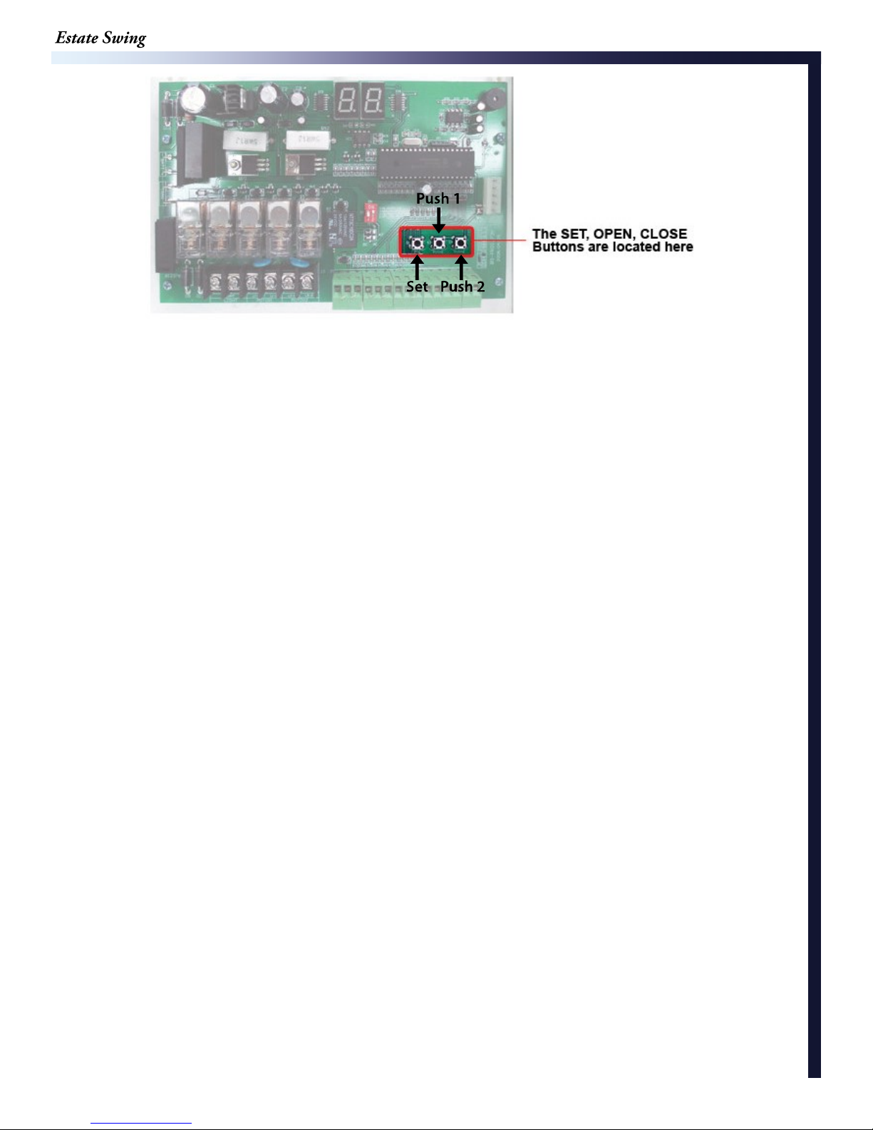
First Run
This is our recommended procedure to run the gate for the first time.
PUSH 1 or PUSH 2 to increase or decrease the parameter. Then press SET button to
move to the next parameter.
1. Press SET button to begin.
2. LED shows P1: Press Push 1 to get P1 setting to 30.
3. Press SET button.
4. LED shows P2: Press Push 1 to get P2 setting to 10.
5. Press SET button.
6. LED shows P3: Press Push 1 to get P3 setting to 30.
7. Press SET button.
8. LED shows P4: Press Push 1 to get P4 setting to 3.
9. Press SET button.
10. LED shows P5: Press Push 1 to get P5 setting to 2.
11. Press SET button.
12. LED shows P6: Press Push 1 to get P6 setting to 10.
13. Press SET to finish. You should hear 3 beeps; this indicates parameter programming
is finished.
Manually unlock the gate, then move it half-way and reengage. Activate using Push 1 button (as shown above)
The gate should run open. Press Push 1 again and it
should run closed. The gate is now set up for regular
usage.
5.1
Operating Parameters Customization
1. LED shows P1: P1 is for setting your run time. The run time exists to allow to have the
P2 slow down setting. This should always be set at least 5 seconds longer than it takes to open
and close. This will allow the gate to go the full motion when moving slower on cold or windy
days. If the number of P1 is reached on the counter during a cycle prior to reaching the limit
switch the gate will stop on the number. The options are 0-99 sec-onds.
2. LED shows P2: P2 is for setting your slow down time. The gate opener will slow down to
partial speed after the counter has reached the setting of P2. If you wish to have the gate
open and close faster make the slow down start time a higher number. If you want to put less
stress on the gears and gate set the slow time lower number. The options will adjust to
match the previously set run time.
3. LED shows P3: P3 is the force setting, the lower the number the easier the gate will
reverse directions when it meets resistance. This number may have to be changed to a higher
setting if your gate is obstructing unexpectedly. The number should be set to the highest number
during initial setup and reduced to the point of reliable operation that takes into account change
in gate resistance through out the year. The options are 0-32.
4. LED shows P4: P4 is for setting a delay between leafs if you have overlapping gates or a
gate lock. The motor wired into the primary terminals (1) opens first if there is a delay and
closes second. It is recommended to have a delay of 3 seconds to avoid any jam-ming issues
between leafs.
5. LED shows P5: P5 is the release for the gate lock – this option determines the length of time
24VDC will be sent out of terminals E_LOCK. The options are 1-4 seconds.
6. LED shows P6: P6 is the delay for automatic re-close from the open position – this op-tion
needs to be turned on using the dip switch on the board. The options are 0-99 sec-onds.
5.2

Estate Swing 433 Plug-in Receiver
1. With the red plug already inside the control box, run the
grey receiver wire out of the box through one of the
water tight connections. DO NOT PERFORM THIS
STEP WITH THE RED PLUG ATTACHED TO THE
CONTROL BOARD.
2. Find a location for the receiver box on the gate post or a
fence post that is within the length of the receiver wire.
3. Using a #6 screw attached the top of the receiver to the
post. If you are happy with this position use the small
provided set screw in the bottom hole to secure the
receiver in place.
4. Attach the receiver wire to the terminals as seen below.
Please note that you will find a factory installed jumper
wire connected on the receiver. Leave this jumper wire
in place. One of the terminals that has the jumper wire
will have the 2nd from the bottom added to the terminal.
1st from the
bottom = V+
2nd from the
bottom = CH1
right (shaped
with jumper)
3rd from the
bottom = CH1
left
5.3

Estate Swing 433 Plug-in Receiver (cont.)
5. Plug the red clip inside the control box into the
control board. The groove in the red clips should
snap into the guide on the 5 prong connector.
6. The red power light should come on the receiver.
7. Program your remotes to the receiver:
A. Press and release the LEARN1 button at the
top of the receiver board (ex 1). The learn LED
will illuminate steady (ex 2). (Fig 1)
B. Press and hold the button on the remote you
wish to program to the receiver.
C. Hold the remote button until the Learn LED
flashes and then turns off. (caution your gate
opener may be triggered during this process)
D. Repeat A through C for all additional remotes.
Fig. 1
NOTES ABOUT REMOTES:
You can program up to 400 codes into the receiver. This could mean 1 button on 400
different remotes or this could mean all 4 buttons on 100 remotes or anything in between.
Some choose to program all 4 buttons to a single receiver if they are not using multiple
gates to eliminate pressing the incorrect button on the remote. To do so follow the programming above with each button of the remote. You can erase all programmed codes
by holding Learn 1 until the Learn LED comes ON and then turns OFF.
8. Put the cover on the receiver and secure it in place using the provided screw.
IMPORTANT: The receiver is a drip proof receiver. This means that it is
designed to prevent water from accessing the inside of the receiver when the water
is moving downward with gravity (rain for example).
DO NOT mount the receiver anyplace that water may access it from another
angle. For example: Do not mount near sprinklers. Do not mount the receiver
horizontally. Do not mount the receiver near a flat surface where water could
splash upwards.
5.4

Maintenance
1) Lubricate the rear pivot and front pivot of the bracket.
2) Lubricate the gate hinges about every 3 months, and also check for
levelness of gate.
6.1

Troubleshooting
If the gate opener will not move but the board is counting the run time:
• Check the F1 fuse for the primary arm (right hand fuse) and the F2 fuse for the secondary arm
(center fuse).
If the gate opener moves a few inches or feet and stops or reverses directions:
• Increase the force setting (P3).
• Check the setback. The setback of the operator is important to correct operation due to leverage
the arm will have on the gate.
Remove the PUSH terminal block and the receiver plug, trigger the gate via BUTTON1, if issue is
resolved one of the accessories or the receiver is double triggering the gate opener.
• For existing gate openers, lubricate the screw drive and pivot points. See maintenance
• section.
The gate does not reach the desired stop points:
• When the gate stops short, press and hold SET to enter PL mode. Depending on open or
closed position, motor 1 or motor 2; use BUTTON1 to scroll to the appropriate indicator O1, C1, O2,
C2. If the BEEPING is on, then the limit switch is triggered and stopped the gate short: if it is a new
installation adjust the limit switch placement. If it is an existing installation it is more likely a bracket
shifted than the limit switch moved. The gate bracket has 3 holes for bolts, if the center bolt is
left out it can shift horizontally on the remaining two bolts. If BEEPING is off then
lengthen the run time parameter (P1).
• Check setback— if setback is incorrect it will limit how far the gate will move per inch of stroke
length.
If the gate will open but will not close:
If the gate is open AND auto-reclose is on when you power the system the board will display AU but
will not go closed. Remove power and move the opener off the open limit switch, when autoreclose is on the gate opener cannot be powered on in the open position. If there was a power outage
this may have occurred accidentally, power down, manually move off open position, and power up
again.
If PH is on the display the safety circuit is triggered. If you have a safety device, it is triggered, if not
using a safety device a jumper is required between terminals PHOTO and GND.
While the gate is open press and hold SET until PL shows on the display. Press BUTTON1 to
scroll to C1 and if dual also scroll to C2. If there is a BEEPING sound on C1 or C2 the closed limit
switch is malfunctioning, closed limit wire is damaged, or (if it is a new installation) wiring is
incorrect. If there is not a BEEPING sound on C1 or C2 in the open position the limit switch is not the
issue.
Remove the PUSH terminal block and receiver. If the gate can then go closed, one of the
accessories or the receiver is malfunctioning.
If auto-reclose is on (dip switch 1 is in up position) AU should be on the display, if it is not press
BUTTON1. If AU then is shown on the display, wait the time closing time that was set in parame-ter
P6. If BUTTON1 or an accessory in PUSH1 is triggered while in AU countdown the countdown will be
paused until pressed again.
6.2

Troubleshooting
The gate opener is moving past a limit switch or switches:
Press and hold SET to enter PL mode. Use BUTTON1 to display the limit switch that is the issue, O1,
C1, O2, C2. Manually move the gate opener from fully retracted to fully extend, listen for a BEEPING.
If BEEPING occurs, stop the piston at the beeping, if this is not your desired position for open or closed
then adjust the limit switch. ON an existing installation, before moving the limit check the brackets for
shifting - the gate brackets has 3 holes for bolts and if only two are used it can shift left or right.
If no BEEPING occurs, use a piece of steel (a washer works well) and locate the magnet inside the
tube assembly (the tube the piston extends in and out of). While the piece of metal is be-ing attracted
to the magnet, move the piston in and out and notate if the magnet is moving. If magnet is NOT moving
a new tube assembly is needed. If magnet IS moving and it is a new dual gate installation check that
Motor 1 is wired to Limit1 block and Motor 2 is wired to Limit 2 block. Check to make ensure the small
yellow, red and black limit wires do not have any part of the bare wire touching each other. Typically
this would be in the terminal itself where the stripped ends are very close to each other. If all the
above is eliminated, a new limit switch is needed.
One or both arms are not moving:
If the gate is open AND auto-reclose is on when you power the system the board will dis-play AU but
will not go closed. Remove power and move the opener off the open limit switch, when auto-reclose is
on the gate opener cannot be powered on in the open position. If there was a power outage this may
have occurred accidentally, power down, manually move off open position, and power up again.
If PH is on the display the safety circuit is triggered. If you have a safety device, it is triggered, if not
using a safety device a jumper is required between terminals PHOTO and GND.
While the gate is halfway between open and closed press and hold SET until PL shows on the
display. Press BUTTON1 to scroll to O1 and C1 and if dual also scroll to O2 andC2. If there is a
BEEPING sound on any of those setting the corresponding limit switch or limit switch wire is the issue.
If it is a new installation review wiring of limit switches.
Remove the PUSH terminal block and receiver. Use BUTTON1 to trigger the gate opener, it it
operates then one of the
accessories or the receiver is malfunctioning.
If auto-reclose is on (dip switch 1 is in up position) AU should be on the display, if it is not press
BUTTON1. If AU then is shown on the display, wait the time closing time that was set in parame-ter
P6. If BUTTON1 or an accessory in PUSH1 is triggered while in AU countdown the countdown will be
paused until pressed again.
• Push or pull on the gate - if it moves the gears are disengaged and the gate is in manual re-lease
mode.
Dual gate - Only one arm moves:
• Check your dual settings - if the dip switch is changed to dual with the power on the setting will not
take effect, turn the power off and then back on to have the dual dip switch take ef-fect. NOTE: If
one leaf of a dual gate ever reaches its end limit before the other leaf starts moving, the leaf that
hasn’t started moving will not begin: correct this by cycling the gates again and let it travel the full
stroke or decrease the delay between leafs. The options are
0-9 seconds delay.
6.3

Troubleshooting
When SET button is pressed and held it immediately changes to P1 instead of PL:
This manual is for circuit boards manufactured after 4/15/15. If you have a previous versions of the
circuit board an updated logic chip can be purchased and installed to make the board operate like the
instructions. Please contact your Estate Swing dealer.
During Limit Programming if BEEPING is not sounding when moving limit switch:
Ensure you are moving the correct limit switch (note Pull to Open vs Push To Open)
If the correct limit switch per the manual is being moved, check to ensure the limit switch wire color
pattern matches the installation (note Pull to Open vs Push To Open)
If the piston is not almost fully retracted, the setback is not correct. The limit switches have limited
travel intentionally to ensure most of the stroke length is used. If the limit switch cannot be adjusted to
reach the magnet trigger when the gate is open the setback has to be moved further from the hinge of
the gate.
During Limit Programming if BEEPING is sounding no matter the position of the limit:
Check wiring connections to ensure the limit switches are connected to the board. If the limit
switches are not connected the BEEPING will sound constantly because the circuit will al-ways be
open.
Ensure the motor 1 limits are wired to limit 1 terminals and, if a dual, motor 2 limits are wired to limit 2
block.
If a single gate opener: unhook the power to the gate opener, move the center dip switch up and
then back to the DOWN position. Reapply power.
Cannot scroll to O2 or C2 settings when in PL programming mode:
Unhook the power to the gate opener, move the center dip switch down and then back to the UP
position. Reapply power. Press and hold the SET button until PL is on the display and then press
BUTTON1 3 times until on O2.
6.4

If you call in for technical support or warranty
support: Before any control board or motor will
be permitted to be sent in for testing or warranty
you will be required to e-mail digital photos to the
technician.
This is done in your best interest to save unnecessary shipping expenses and time lost.
Many times we can come up with solutions to issues by seeing pictures that relay information
that is impossible to relay through a phone conversation.
Below are examples of control board pictures and motor pictures that we will be looking for:
Pictures shown are actual customer photos
6.5

Control Board Overview
CAUTION! Do not run 110V AC power direct to the board. This
will cause permanent damage to both boards and void your
warranty. Caution!
Gate Opener reactions to signals:
PUSH1 and Receiver (PUSH 1 terminal, PUSH 1 button, 5 Prong
Receiver):
Details:
• Will activate gate with momentary contact (momentary contact between PUSH1 and V+)
or if you momentarily press the PUSH1 button.
• Controls both leaves in 2 leaf mode (Dip switch 2 in the ON position).
• Acts as party mode control to suspend auto-reclose by activating while counting down auto-
reclose in the open position.
Operational Sequence for terminal with auto-close ON (Dip switch 1 in on position):
1. In closed position - momentary contact will open gates.
2. When opening - momentary contact will stop gates and then it will auto reclose.
3. When stopped mid cycle waiting auto reclose - momentary contact will move the gate in
the direc-tion opposite what it was moving before stopped.
4. When open and counting auto-reclose pause time - momentary contact will stop pause
time.
5. Stopped in open position from override of auto-reclose from PUSH1 or Receiver momentary contact will reactivate pause time and close gate.
6. When closing - momentary contact will stop the gate and then it will auto reclose.
Operational Sequence for terminal with auto-close OFF (Dip switch 1 in off position):
1. In closed position - momentary contact will open gates.
2. When opening - momentary contact will stop gates.
3. When stopped mid cycle - momentary contact will move the gate in the
direction opposite what it was moving before stopped.
4. When open - momentary contact will close gates.
5. When closing - momentary contact will stop the gate.
6. When stopped mid cycle - momentary contact will open the gate.
7. When open with auto-reclose off - momentary contact will have no effect.
8. When closing - momentary contact will re-open the gate.
7.1

Control Board Overview
CAUTION! Do not run 110V AC power direct to the board. This
will cause permanent damage to both boards and void your
warranty. Caution!
Gate Opener reactions to signals:
PUSH2 (PUSH 2 terminal and PUSH 2
button):
Details:
• Will activate gate with momentary contact (momentary contact between PUSH2
and V+).
• Controls both leaves in 2 leaf mode (Dip switch 2 in the ON position)
• Only opens the gate, never closes it.
• Pause time is able to be re-set if this terminal is closed through a momentary contact.
Then the time will be reset, count down the pause time, and reclose.
• Ideal for exit wand or exit loop.
Operational Sequence for terminal with auto-close ON (Dip switch 1 in on position):
1. In closed position - momentary contact will open gates.
2. When opening - momentary contact will have no effect.
3. When stopped mid cycle from PUSH 1 or the Receiver - momentary contact will open the
gate.
4. When open with auto-reclose on - momentary contact will re-set pause time and will start
counting again after release of momentary contact.
5. When pause time countdown is stopped in open from a momentary contact of PUSH 1 or
the Receiv-er - momentary contact will have no effect.
6. When closing - momentary contact will re-open the gate.
Operational Sequence for terminal with auto-close OFF (Dip switch 1 in off position):
1. In closed position - momentary contact will open gates.
2. When opening - momentary contact will have no effect.
3. When stopped mid cycle - momentary contact will open the gate.
4. When open with auto-reclose off - momentary contact will have no
effect.
5. When closing - momentary contact will re-open the gate.
PUSH 1 and PUSH 2 – these terminals can hold as many normally open connections as
needed, they will be wired in parallel. They are used for keypads, push buttons, universal
receivers, etc.
7.2

Control Board Overview
Light:
Motor 1:
Motor 2:
Limit 1:
Limit 2:
Sends pulses of 24VDC only while gate is running, and whether it is
open or closed.
L1-1, L1-2 = 24VDC power to single motor or primary motor
L2-1, L2-2 = 24VDC power to secondary motor
OL1 = Open limit for single motor or primary
(normally closed) V+ = Common for limits,
+12VDC
CL1 = Closed limit for single motor (normally
closed)
OL2 = Open limit for secondary motor
(normally closed) V+ = Common for limits,
+12VDC
CL2 = Closed limit for secondary motor
(normally closed)
Photocell:
Button:
E_Lock:
Fuses:
Photo = Input for safety eye photo beam connection (normally closed)
GND = Ground for photocell power/ground for photo
connection V+ = +12VDC, Max 100 milliamps for photocell
power
+24V = +24VDC, Max 200 milliamps for accessory power
PUSH 1 = Ground for Push 1 Accessory
*PUSH 1 / V+ is for push buttons, keypads, receivers, or any other dry
and momentary contact.
COM = Positive voltage +12VDC for Push 1 or Push 2 accessory
(relay only, not main power)
PUSH 2 = Ground for Push 2 accessory
*PUSH 2 / V+ is for exit wand, exit loops or other open only dry
contact and momentary contact
Solenoid lock output - 12VDC (4 Amp max)
A = Positive B = Negative
F1 = 8A 250V, protects motor 1
F2 = 8A 250V, protects motor 2
F3 = 2A 250V, protects accessory output
+24V
7.3

Control Board Overview
CAUTION! Do not run 110V AC power direct to the board. This
will cause permanent damage to both boards and void your
warranty. Caution!
Display Indicators:
Buzzer / Obstructions:
Lights off on board & stand by / normal operation
Lower right hand “dots” flashing normal pace:
Active / Awaiting command
EL: Sending voltage to EL ter minals (electric lock)
OP: Opening cycle
AU: Auto-reclose countdown
CL: Closing cycle
PH: Photo cell disr uption
If the gate(s) come in contact with an obstruction the
gate(s) will reverse direction for 2 seconds and stop to allow
the obstacle to be cleared from the gate path.
If the gate(s) obstructs 3 times in a row the gate(s) will go
into a hard shutdown mode and a buzzer alarm will sound.
At this point no accessories or remotes will be able to
activate the gate opener until the gate opener is reset by
disconnecting primary power bat-tery.
7.4

Accessory Wiring
The manufacturer instructions that come with your accessory should have markings for wires
or terminals to connect to the gate opener. Please look for terminals named below in the
instructions for the accessory.
Keypads, Receivers:
Normally Open (NO) or Input (INP) or Relay of entry device = COM ter minal (to right of PUSH1) of
PUSH block on gate opener control board.
Common (COM) or Ground (GND) or Relay of entry device = PUSH1 ter minal of PUSH block
on gate opener control board.
NOTE: If the power for the accessor y shares a Ground wir e/terminal with the relay – Do Not power
that ac-cessory off this control board (example: WKP-P keypad). Instead power that device with
batteries.
24V Power positive (+) or (24V) or (PWR) of entry device = +24V terminal of PHOTO block on gate
opener control board.
24V Power Negative (-) or (GND) or (PWR) of entry device = GND ter minal of PHOTO block on
gate open-er control board.
Push Button, Intercoms:
Normally Open (NO) or Input (INP) or Relay of entry device = COM ter minal (to right of PUSH1) of
PUSH block on gate opener control board.
Common (COM) or Ground (GND) or Relay of entry device = PUSH1 ter minal of PUSH block
on gate opener control board.
Push buttons do not require power and Intercoms draw too much power to power from the gate opener.
Exit Wand/Sensor, Exit Loop Detector, Exit Device:
Normally Open (NO) or Input (INP) or Relay of exit device = COM ter minal (to right of PUSH2) of
PUSH block on gate opener control board.
Common (COM) or Ground (GND) or Relay of exit device = PUSH2 ter minal of PUSH block on gate
opener control board.
24V Power positive (+) or (24V) or (PWR) of exit device = +24V terminal of PHOTO block on gate
opener control board.
24V Power Negative (-) or (GND) or (PWR) or Shield wire of exit device = GND ter minal of
PHOTO block on gate opener control board.
7.5

Accessory Wiring
Photo Eye, Safety Edge, Safety Loop:
Normally Closed (NC) of safety device = Photo terminal of PHOTO block on gate opener contr ol
board. Common (COM) or Ground (GND) of safety device = GND ter minal of PHOTO block on
gate opener con-trol board.
12V Power positive (+) or (12V) or (PWR) of safety device = V+ ter minal of PHOTO block on gate
opener control board.
12V Power Negative (-) or (GND) or (PWR) of safety device = GND terminal of PHOTO block on
gate open-er control board.
*Remove safety jumper from PHOTO terminal if using a safety
device.
*
12V is not a misprint, the V+ terminal has a 12V output.
Solenoid Gate Lock:
Positive Lead of lock = A terminal of E_LOCK block on gate opener contr ol
board. Negative Lead of lock = B terminal of E_LOCK block on gate opener
control boar d.
Magnetic Gate Lock: Magnetic gate lock s must have their own power supply and their
own relay.
Coil of relay for magnetic lock = A terminal of E_LOCK block on gate opener contr ol board.
Coil of relay for magnetic lock = B terminal of E_LOCK block on gate opener contr ol board.
Connect positive lead of the power supply directly to the positive lead of the mag lock.
Connect negative lead of the power supply to the N/C terminal of the relay.
Connect the COM terminal of the relay to the negative lead of the mag lock.
7.6
 Loading...