


TS25AFXKQ05
Estate TS25AFXKQ05, TS25AFXKQ07, TS25AFXKQ08, TS25AFXKS05, TS25AFXKS07 Installation Guide
...
I STRUCTIO EET
For "in the Grill Filter" Water Valve
ElectricalShock Hazard
Disconnect power before servicing.
Replace all parts and panels before
operating.
Failure to do so can result in death
or electrical shock.
g,
10.
11.
12.
NOTE:
Replace the unit compartment cover and reconnect main
water supply.
Turn main water supply on and check for leaks.
Flush the water system. Please refer to the "flushing the
water system" section.
Cycle dispenser and icemaker. Check for leaks and proper
operation of dispenser and icemaker.
Pictures may vary from actual product.
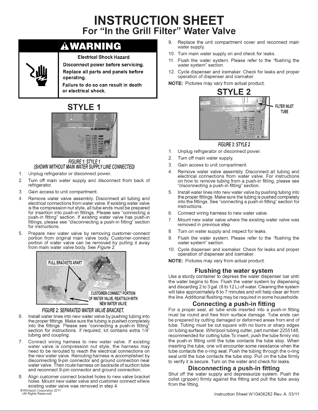
STYLE 2
STYLE I
FIGURE1:STYLE1
FILTERINLET
TUBE
1,
2.
3,
4.
5,
(SHOWNWITHOUTMAINWATERSUPPLYLINECONNECTED)
Unplug refrigerator or disconnect power.
Turn off main water supply and disconnect from back of
refrigerator.
Gain access to unit compartment.
Remove water valve assembly. Disconnect all tubing and
electrical connections from water valve. If existing water valve
is the compression nut style, all tube ends must be prepared
for insertion into push-in fittings. Please see "connecting a
push-in fitting" section. If existing water valve has push-in
fittings, please see "disconnecting a push-in fitting" section
for instructions.
Prepare new water valve by removing customer-connect
portion from original main valve body. Customer-connect
portion of water valve can be removed by pulling it away
from main water valve body. See Figure 2.
CUSTOMER-CONNECTPORTION
)FWATERVALVE.REATTACHWITH
NEWWATERVALVE
FIGURE2:SEPARATEDWATERVALVEBRACKET.
6. Install water lines into new water valve by pushing tubing into
the proper fittings. Make sure the tubing is pushed completely
into the fittings. Please see "connecting a push-in fitting"
section for instructions. If required, kit contains extra 1/4"
tubing and coupling.
7. Connect wiring harness to new water valve. If existing
water valve is compression nut style, the harness may
need to be rerouted to reach the electrical connections on
the new water valve. Rerouting harness is accomplished by
disconnecting 9-pin connector and ground connection near
water valve. Then route harness on backside of suction tube
and reconnect 9-pin connector and ground connection.
8. Align customer connect bracket holes to new valve bracket
holes. Mount new water valve and customer connect where
existing water valve was removed in step 4.
@Whirlpool Corporation 2011
(All Rights Reserved)
1,
2.
3.
4.
5,
6,
7.
8.
9.
10.
NOTE:
FIGURE3:STYLE2
Unplug refrigerator or disconnect power.
Turn off main water supply.
Gain access to unit compartment.
Remove water valve assembly. Disconnect all tubing and
electrical connections from water valve. For instructions
on how to remove tubing from a push-in fitting, please see
"disconnecting a push-in fitting" section.
Install water lines into new water valve by pushing tubing into
the proper fittings. Make sure the tubing is pushed completely
into the fittings. See "connecting a push-in fitting" section for
instructions.
Connect wiring harness to new water valve.
Mount new water valve where the existing water valve was
removed in previous step.
Turn on water supply and inspect for leaks.
Flush the water system. Please refer to the "flushing the
water system" section.
Cycle dispenser and icemaker. Check for leaks and proper
operation of dispenser and icemaker.
Pictures may vary from actual product.
Flushing the water system
Use a sturdy container to depress the water dispenser bar until
the water begins to flow. Flush the water system by dispensing
and discarding 2 to 3gal. (8 to 12 L) of water. Cleaning the system
wilt take approximately 6 to 7 minutes and wilt help clear air from
the line. Additional flushing may be required in some households.
Connecting a push-in fitting
For a proper seal, all tube ends inserted into a push-in fitting
must be round and free from surface damage. Tube ends can
be prepared by cutting damaged or deformed areas from end of
tube. Tubing must be cut square with no burrs or sharp edges
on tubing surface. Whirlpool tubing cutter, part number 2255148,
recommended for cutting tube.To insert, push the tube firmly into
the push-in fitting until the tube contacts the tube stop. When
inserting the tube, one will encounter some resistance when the
tube contacts the o-ring seal. Push the tubing through the o-ring
seat until the tube contacts the tube stop. Pull on the tube firmly
to verify it is secure. Turn on the water and check for leaks.
Disconnecting a push-in fitting
Shut off the water supply and depressurize system. Push the
collet (gripper) firmly against the fitting and pull the tube away
from the fitting.
Instruction Sheet W10406282 Rev. A 03/11
 Loading...