

Estate IRE32303, YKERA205PB6, IRP85804, IRP33803, YKERA205PS6 Installation Instructions Manual
...
INSTALLATIONINSTRUCTIONS
30" (76 CM) FREESTANDINGELECTRICRANGES
I_STRUCTIONS D'INSTALLATION DESCUISINIERES
ELECTRIQUESAUTOPORTANTESDE 30" (76 CM)
TableofContents/Table des mati@res
RANGE SAFETY ............................................................................. 2
INSTALLATION REQUIREMENTS ................................................ 3
Tools and Parts ............................................................................ 3
Location Requirements ................................................................ 3
Electrical Requirements ............................................................... 4
INSTALLATION INSTRUCTIONS .................................................. 5
Unpack Range .............................................................................. 5
Install Anti-Tip Bracket ................................................................. 5
Verify Anti-Tip Bracket Location .................................................. 6
Level Range .................................................................................. 6
Complete Installation ................................................................... 7
Moving the Range ........................................................................ 7
ANTI-TIP BRACKET TEM PLATE ................................................ 16
SECURITI :!:DE LA CUISINII_RE ..................................................... g
EXIGENCES D'INSTALLATION ................................................... 10
Outillage et pieces ...................................................................... 10
Exigences d'emplacement ......................................................... 10
Specifications electriques .......................................................... 11
INSTRUCTIONS D'INSTALLATION ............................................. 12
Deballage de la cuisiniere .......................................................... 12
Installation de la bride antibasculement .................................... 12
Verification de I'emplacement de la bride antibasculement ...... 13
Mise a niveau de la cuisiniere .................................................... 13
Achever I'installation .................................................................. 14
Deplacement de la cuisiniere ..................................................... 14
GABARIT POUR LA BRIDE ANTIBASCULEMENT .................... 16
iMPORTANT:
Save for local electrical inspector's use.
iMPORTANT :
A conserver pour consultation par I'inspecteur local des installations electriques.
W10141167A
RANGESAFETY
Your safety and the safety of others are very important.
We have provided many important safety messages in this manual and on your appliance. Always read and obey all safety
messages.
This is the safety alert symbol.
This symbol alerts you to potential hazards that can kill or hurt you and others.
All safety messages will follow the safety alert symbol and either the word "DANGER" or "WARNING."
These words mean:
You can be killed or seriously injured if you don't immediately
follow instructions.
You can be killed or seriously injured if you don't follow
instructions.
All safety messages will tell you what the potential hazard is, tell you how to reduce the chance of injury, and tell you what can
happen if the instructions are not followed.
,_ A child or adult can tip the range and be killed.
Connect anti-tip bracket to rear range foot.
' Reconnect the anti=tip bracket, if the range is moved.
I I Tip Over Hazard
Failure to fellow these instructions can result in death or serious burns to children and adults.
INSTALLATIONREQUIREMENTS
Gather the required tools and parts before starting installation.
Read and follow the instructions provided with any tools listed
here.
Tools needed
• Tape measure • %" drive ratchet
• Flat-blade screwdriver • 1A"nut driver
• Level • %" and %6" nut driver
• Hammer • 1/8"(3.2 mm) drill bit (for
• Hand or electric drill wood floors)
• Wrench or pliers • s/16"(4.8 mm) carbide-tipped
• Marker or pencil concrete/ceramic floors)
• Masking tape
Parts supplied
Check that all partsare included.
masonry drill bit (for
A
• Cabinet opening dimensions that are shown must be used.
Given dimensions are minimum clearances.
• The floor anti-tip bracket must be installed. To install the anti-
tip bracket shipped with the range, see "Install Anti-Tip
Bracket" section.
• Grounded electrical supply is required. See "Electrical
Requirements" section.
IMPORTANT: To avoid damage to your cabinets, check with your
builder or cabinet supplier to make sure that the materials used
will not discolor, delaminate or sustain other damage. This oven
has been designed in accordance with the requirements of UL
and CSA International and complies with the maximum allowable
wood cabinet temperatures of 194 ° (90°C).
Product Dimensions
)
A. Anti-tip bracket
B. Plastic anchors (2)
C. #10 x l _" screws (2)
Anti-tip brackets must be securely mounted to subfloor.
Thickness of flooring may require longer screws to anchor
bracket to subfloor. Longer screws are available from your
local hardware store.
Parts needed
Check local codes. Check existing electrical supply. See
"Electrical Requirements" section.
All electrical connections should be made by a licensed, qualified
electrical installer.
IMPORTANT: Observe all governing codes and ordinances,
• It is the installer's responsibility to comply with installation
clearances specified on the model/serial rating plate. The
model/serial rating plate is located on the oven frame behind
the storage drawer panel,
• The range should be located for convenient use in the
kitchen.
To eliminate the risk of burns or fire by reaching over heated
surface units, cabinet storage space located above the
surface units should be avoided. If cabinet storage is to be
provided, the risk can be reduced by installing a range hood
that projects horizontally a minimum of 5" (12.7 cm) beyond
the bottom of the cabinets.
B
E
A. 27 _" (68.9 cm) depth with handle
28 _" (71.6 cm) depth with handle (KitchenAid models only)
B. 46 _" (119.1 cm) overafl height
46" (116.8 cm) overall height (KitchenAid models only)
C. 46" (91.4 cm) cooktop height
D. 29_" (75.9 cm) width
E.24 1_6" (63.0 cm) depth
F. Model/serial rating plate (located on the left side frame behind
storage drawer panel)
Cabinet Dimensions
Cabinet opening dimensions shown are for 25" (64.0 cm)
countertop depth, 24" (61.0 cm) base cabinet depth and
36" (91.4 cm) countertop height.
If installing a range hood or microwave hood combination above
the range, follow the range hood or microwave hood combination
installation instructions for dimensional clearances above the
cooktop surface.
A freestanding range may be installed next to combustible walls
with zero clearance.
I F
\
\
Electrical Shock Hazard
Electrically ground range.
Failure to do so can result in death, fire, or
electrical shock.
If codes permit and a separate ground wire is used, it is
recommended that a qualified electrical installer determine that
the ground path is adequate and wire gauge are in accordance
with local codes.
Be sure that the electrical connection and wire size are adequate
and in conformance with CSA Standard C22.1, Canadian
Electrical Code, Part 1 - latest edition, and all local codes and
ordinances.
A copy of the above code standards can be obtained from:
Canadian Standards Association
178 Rexdale Blvd.
Toronto, ON M9W 1R3 CANADA.
• Check with a qualified electrical installer if you are not sure
the range is properly grounded.
A. 13" (33.0 cm) max. upper cabinet depth
B. 30" (76.2 cm) min. opening width
C. For minimum clearance to top of cooktop, see NOTE*
D. 31 _" (79.0 cm) min. opening width
E.Outlet - 8" (20.3 cm) to 22" (55.9 cm) from either cabinet,
7" (17.8 cm) max. from floo_
F. _" (2.2 cm) min. required between cutout and cabinet door or
hinge.
*NOTE: 24" (61 cm) minimum when bottom of wood or metal
cabinet is protected by not less than 1/4"(0.64 cm) flame
retardant millboard covered with not less than No. 28 MSG
sheet steel, 0.015" (0.4 mm) stainless steel, 0.024" (0.6 mm)
aluminum or 0.020" (0.5 mm) copper.
30" (76.2 cm) minimum clearance between the top of the
cooking platform and the bottom of an unprotected wood or
metal cabinet.
Range Rating* Specified Rating of
Power Supply Cord Kit
and Circuit Protection
120/240 Volts 120/208 Volts Amps
8.8- 16.5 KW 7.8- 12.5 KW 40 or 50"*
16.6 - 22.5 KW 12.6- 18.5 KW 50
*The NEC calculated load is less than the total connected load
listed on the model/serial rating plate.
**If connecting to a 50-amp circuit, use a 50-amp rated cord with
kit. For 50-amp rated cord kits, use kits that specify use with a
nominal 1%" (34.9 mm) diameter connection opening.
• A time-delay fuse or circuit breaker is recommended.
This range is equipped with a CSA International Certified
Power Cord intended to be plugged into a standard 14-50R
wall receptacle. Be sure the wall receptacle is within reach of
range's final location.
• Do not use an extension cord.
INSTALLATIONINSTRUCTIONS
U " pcsck
Excessive Weight Hazard
Use two or more people to move and install range.
Failure to do so can result in back or other injury.
1. Remove shipping materials, tape and protective film from
range. Remove oven racks and parts package from inside
oven.
2. Do not remove the shipping base at this time.
A. Shipping base
3,
On Ranges Equipped with Storage Drawers:
Remove the storage drawer. Use a 3/8"drive ratchet to lower
the rear leveling legs one-half turn. Use a wrench or pliers to
lower front leveling legs one-half turn.
On Ranges Equipped with Warming Drawers:
Use wrench or pliers to lower the front and rear leveling legs
one-half turn.
A
D
/// C
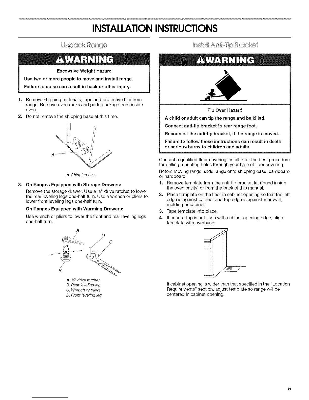
Tip Over Hazard
A child or adult can tip the range and be killed.
Connect anti-tip bracket to rear range foot.
Reconnect the anti=tip bracket, if the range is moved.
Failure to follow these instructions can result in death
or serious burns to children and adults.
Contact a qualified floor covering installer for the best procedure
for drilling mounting holes through your type of floor covering.
Before moving range, slide range onto shipping base, cardboard
or hardboard.
1. Remove template from the anti-tip bracket kit (found inside
the oven cavity) or from the back of this manual.
2. Place template on the floor in cabinet opening so that the left
edge is against cabinet and top edge is against rear wall,
molding or cabinet.
3. Tape template into place.
4. If countertop is not flush with cabinet opening edge, align
template with overhang.
B
A. _" drive ratchet
B.Rearleveling leg
C. Wrench or pliers
D.Front leveling leg
If cabinet opening is wider than that specified in the "Location
Requirements" section, adjust template so range will be
centered in cabinet opening.
 Loading...