

Estate gas dryer Installation Instructions Manual
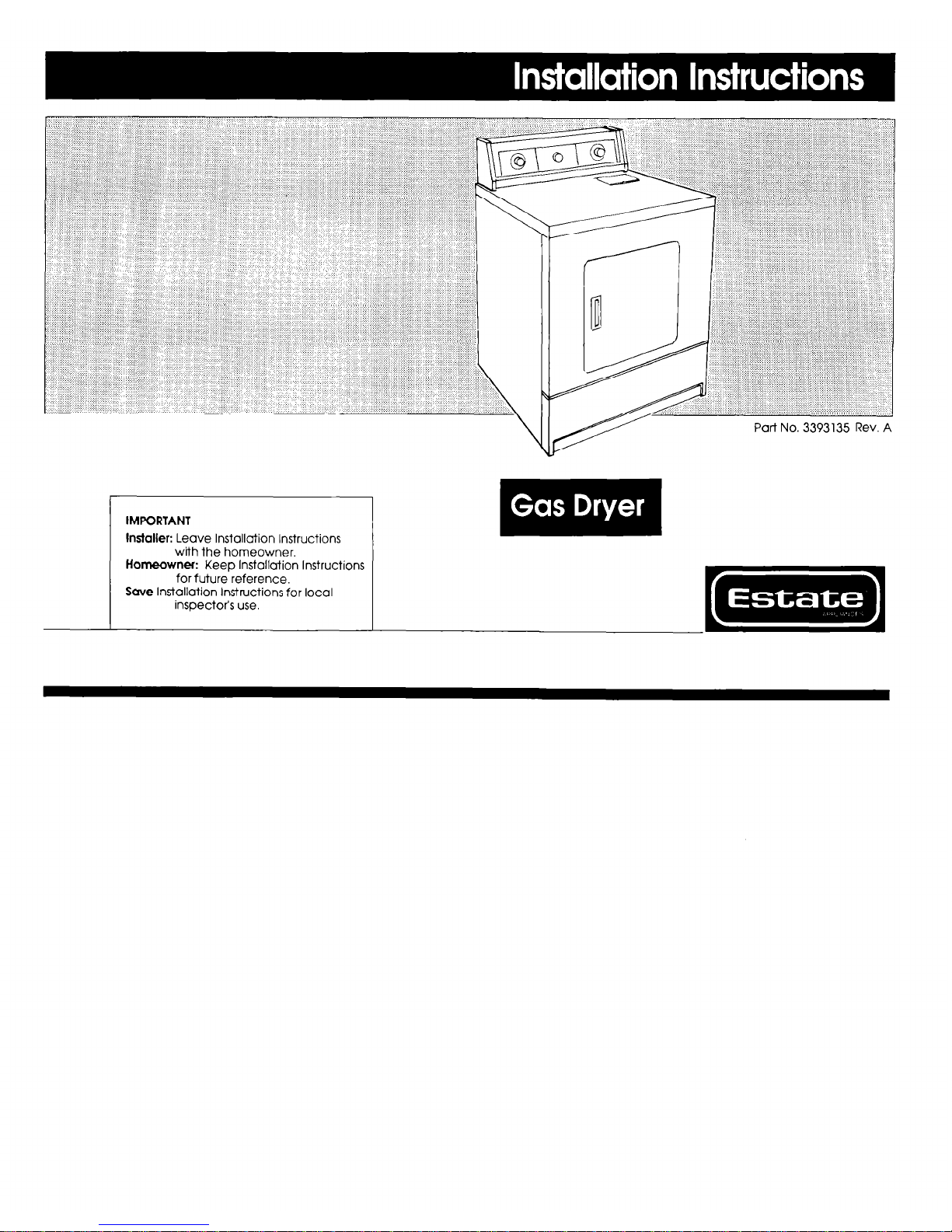
Part No. 3393135 Rev. A
IMPORTANT
Installer: Leave lnstollution Instructions
with the homeowner.
Homeowner: Keep Installation Instructions
for future reference.
Save Installation Instructions for local
inspectof s use.
Before you
start...
Fire Hazard
. Never install dryer up
against draperies or curtains
or on carpet.
. Keep any and all tterns from
failing or collecting behind
the dryer.
. Replace all access panels
before operaling dryer.
Failure to follow these
instructions could result in a
fire or explosion.
. II you smell gas:
1. Ooen windows.
2. Don’t iouch electrlcal
switches.
3. Extinguish any open flOt?W.
4. lmmedialety call your gas
supplier.
. Do Not store or use gasoline,
paint, thinners and other
flarnrmMe matertats near
washer/dryer.
Fumes from such materials could
result in fire or explosion.
Mark an X across the
letter or
number as You complete eacn step
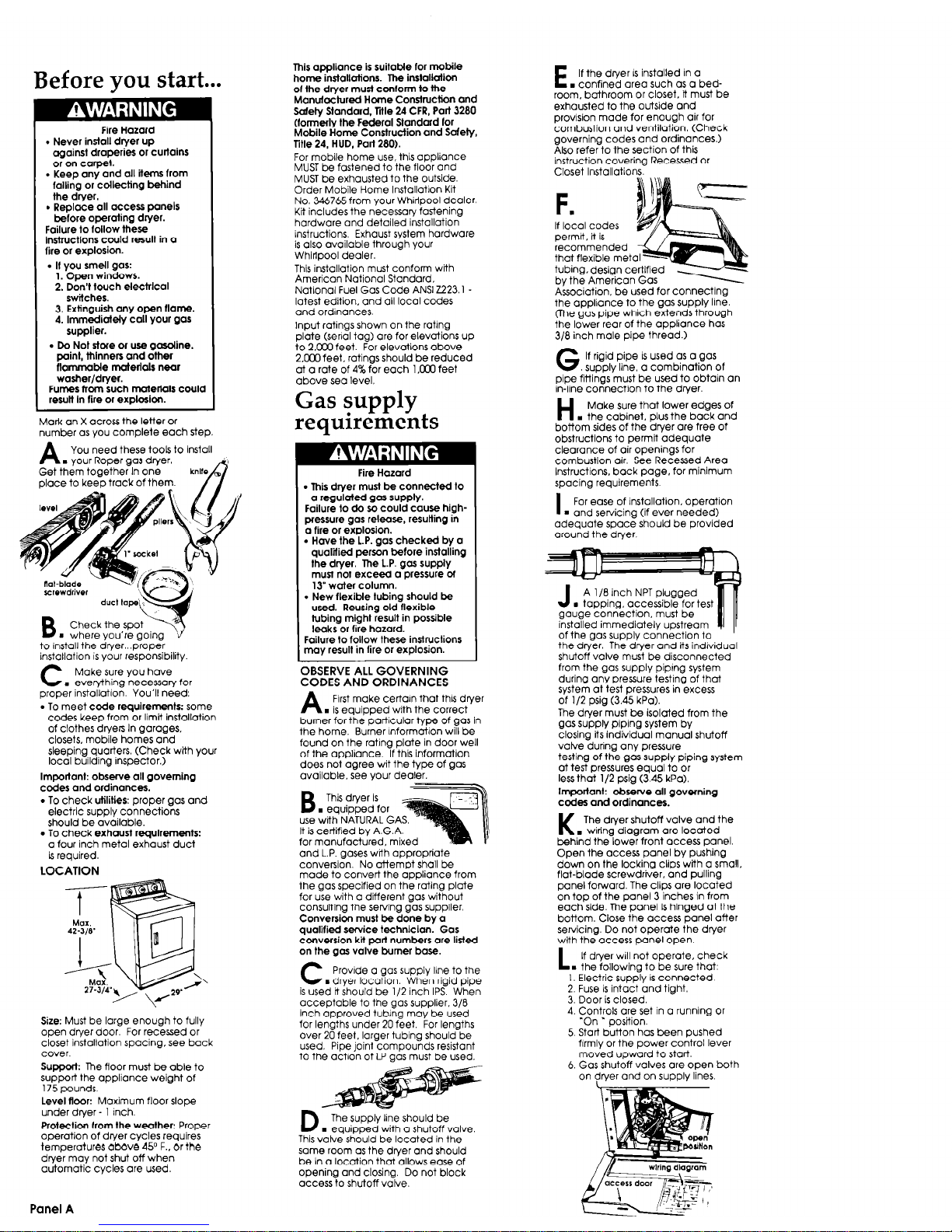
A
You need these tools to Install
. Your Roper gas dryer.
Get them together In one
place to keep track of them.
B
Check the spot
m where you’re going
to install the drver...orooer
installation is your responsibility
C
Make sure you have
. everything necessay for
proper instollotlon. You’ll need:
. To meet code requirements: some
codes keep from or limit installation
of clothes dryers In garages,
closets, mobile homes and
sleeping quarters. (Check with your
local building inspector.)
Important: observe all governing
codes and ordinances.
. To check utilities: proper gas and
electric supply connectio-m
should be available.
. To check exhaust requirements:
o four inch metal exhaust duct
is required.
LOCATION
Size: Must be large enough to fully
open dryer door. For recessed or
closet installation spacing, see back
cover.
Support The floor must be able to
support the appliance weight of
175 pounds.
Level floor: Maximum floor slope
under dlyer - 1 inch.
Protection from the weother: Proper
operation of dryer cycles requires
temperatures above 45O F., or the
dryer may not shut off when
automatic cycles ore used.
This appliance is suitable for mobile
home installations. The installcrlion
of the dryer must conform to the
Manufactured Home Construction and
Safely Standard, Mle 24 CFR, Part 3280
(formerly the Federal Standard for
Mobile Home Construction and Safety,
Title 24, HUD, Part 280).
For mobile home use. this appliance
MUST be fastened to the floor and
MUST be exhausted to the outside.
Order Mobile Home lnstallotron Kit
NO. 346765 from Your Whirlpool dealer
Kit includes the necessary fastening
hardware and detailed installation
instructions. Exhaust system hardware
is also available through your
Whirlpool dealer.
This installation must conform with
American National Standard.
National Fuel Gas Code ANSI 2223.1 latest edition, and all loco1 codes
and ordinances.
Input ratinas shown on the rating
plbte (serki tag) are for elevations up
to 2.ooO feet. For elevations above
2.Mx) feet. ratings should be reduced
at o rate of 4% for each 1 .ooO feet
above seo level.
Gas supply
requirements
. This dryer must be connected lo
cr regulated gas supply.
Failure to do so could cause highpressure gas release, resulting in
a fire or explosion.
l
Have the L.P. gas checked by a
qualttied person before installing
the dryer. The L.P. gos supply
must not exceed a pressure d
13” water column.
. New flexible tubing should be
used. Reusing old flexible
tubing might result in possible
leaks or fire hozord.
Failure to follow these instructions
may result in fire or explosion.
OBSERVE ALL GOVERNING
CODES AND ORDINANCES
A
Frrst make certain that this dryer
. is equipped with the correct
burner for the particular type of gas in
the home. Burner lnformotion will be
found on the ratrng plate in door well
of the appliance. If this informution
does not agree wit the type of gas
available. see vour dealer.
B
This dryer is
. equipped for
use with NATURAL GA
It is certified by A.G.A.
for manufactured, mixe
and L.P. gases wdh appropriate
conversion. No attemot shall be
made to convert the dppliance from
the gas specaied on the rating plate
for use with a different gos without
consultina the sewincl ~10s suoolier.
Conversi& must be d&e by b
qualified service technician. Gas
conversion kii poll numbers ore listed
on the gos valve burner base.
C
Provide CI gas supply line to the
. dryer location. When rigid pipe
is used tt should be l/2 inch IPS. When
acceptable to the gas supplier, 3/8
inch approved tubng may be used
for lengths under 20 feet. For lengths
over 20 feet. larger tubing should be
used. Pipe joint compounds resistant
to the actron of LP QOS must be used.
D
The supply line should be
. equipped with CI shutoff valve.
This valve should be located in the
same room as the dryer and should
be in a location that allows ease of
opening and closing. Do not block
access to shutoff valve.
E
If the dryer IS installed In o
. confined area such as a bedroom, bathroom or closet. it must be
exhausted to the outside and
provision made for enough air for
combustion and ventilation. (Check
governing codes and ordinances.)
Also refer to the section of this
instruction covering Recessed or
Closet Installations.
F
.
If local codes
permit, it is
recommended
that flexible me
tubing. design
by the Americ
Associution. be used for Connecting
the appliance to the gas supply Ilne.
(The gas pipe which extends through
the lower rear of the appliance has
3/8 inch male pipe thread.)
G.
If rigid pipe IS used as a gas
supply line, a combination of
pipe fittings must be used to obtain on
in-line connection to the dryer.
H
Make sure that lower edges of
. the cabinet. plus the back and
bottom sides of the dryer are free of
obstructions to perma adequate
clearance of air ooeninas for
combustion air. See Recessed Area
Instructions. back page, for minimum
spacing requirements.
I
For ease of installation, operation
m and servicing (if ever needed)
adequate space should be provided
around the dryer.
8 inch NPT plugged
ping. accessible fort
onnection. must be
immediately upstream
of the gas supply connection to
the dryer. The dryer and its indrvidual
shutoff valve must be disconnected
from the gas supply piprng system
durina anv oressure testrna of that
system at test pressures inexcess
of l/2 psig (3.45 kPa).
The dryer must be isolated from the
gas supply piping system by
closing its individual manual shutoff
vahe during any pressure
testing of the gas supply piping system
at test pressures equal to or
less that l/2 psig (3.45 kPa).
Important: observe all governing
codes and ordinances.
K
The dlyer shutoff valve and the
. wiring diagram are located
behind the lower front access panel.
Open the access ponel by pushing
down on the locking clips with CI small.
flat-blade screwdriver. and pulling
panel forward. The clips are located
on top of the panel 3 inches in from
each side. The panel is hinged at the
bottom. Close the access panel after
servicing. Do not operate the dryer
with the access Dane1 ooen.
L ”
If dryer will not operate, check
. the followina to be sure that:
I. Electric sup& is connected
2. Fuse is intact and tight.
3. Door is closed.
4. Controls are set in 0 running or
‘On * oosition.
5 Start button has been pushed
firmly or the power control lever
moved upward to start
6. Gas shutoff valves ore open both
on dryer and on supply lines.
Panel
A
 Loading...