

Page 1
SIGA2-PHS(B) Intelligent 3D Multisensor PhotoHeat Detector Installation Sheet
Installation
Notes
• This detector does not operate without electrical power. As
fires frequently cause power interruption, discuss further
safeguards with the local fire protection specialist.
• This detector does not sense fires in areas where smoke
Description
The Signature Series Intelligent 3D Multisensor Photo-Heat
Detector is an intelligent device that contains a photoelectric
smoke sensor and a fixed-temperature heat sensor. There are
two models: SIGA2-PHS is white; SIGA2-PHSB is black.
LED indicator. The LED indicator (see Figure 1 below)
displays the following states:
• Normal: Green LED indicator flashes, no action.
• Alarm/active: Red LED indicator flashes, evacuate the
area.
• Stand-alone alarm: Red LED indicator turns on, evacuate
the area.
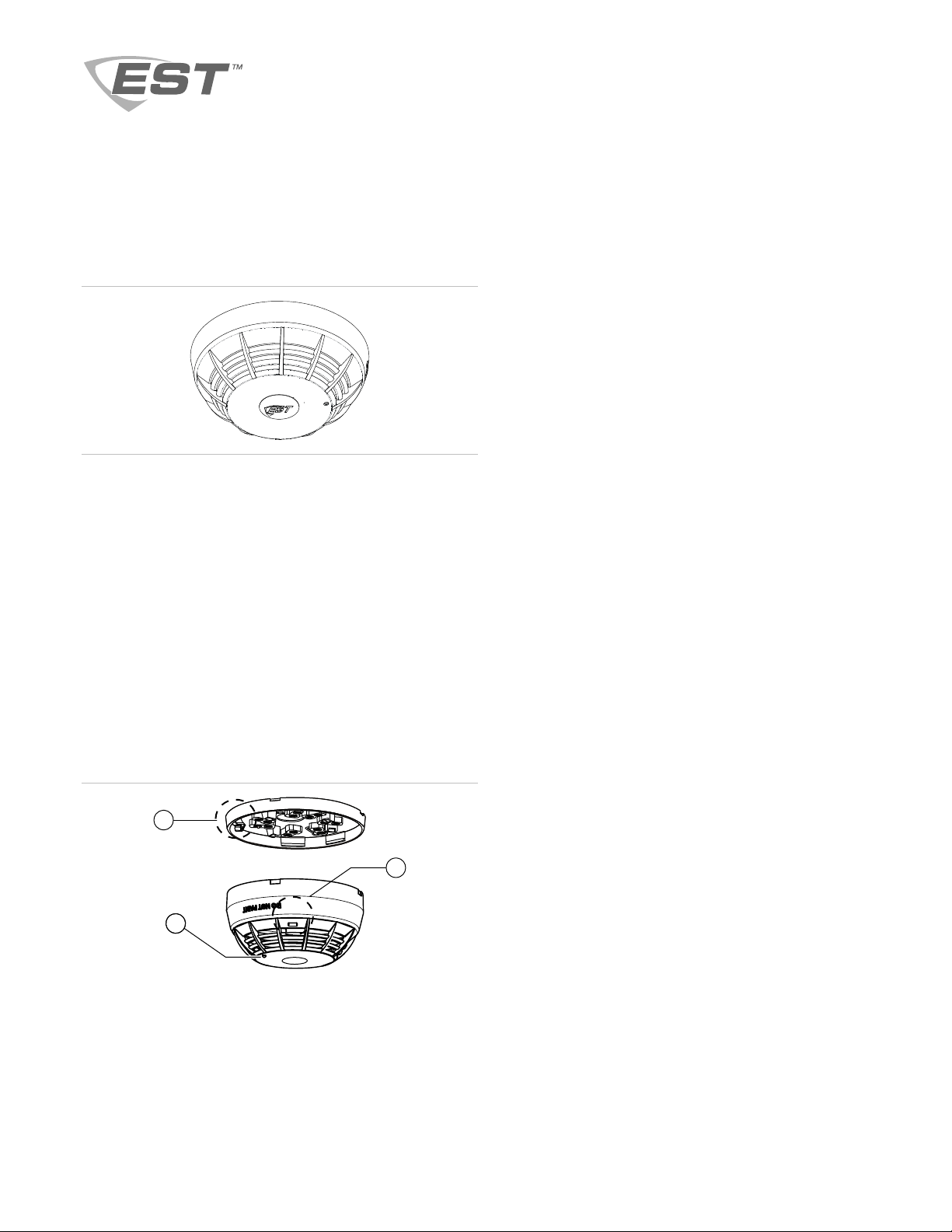
Figure 1: SIGA2-PHS(B) features
or heat cannot reach the detector. Smoke or heat from
fires in walls, roofs, or on the opposite side of closed doors
may not reach the detector.
• Photoelectric detectors have a wide range of sensing
capabilities, and are best suited for detecting slow,
smoldering fires. The heat sensor in this device provides a
source of supplemental information. The heat sensor by
itself does not provide life safety protection.
• To ensure proper operation, store the detector within the
recommended ranges. Allow the detector to stabilize to
room temperature before applying power.
• The dust cover (supplied) must remain on the detector
during installation and be removed prior to commissioning
and service. The dust cover is not a substitute for
removing the detector during new construction or heavy
remodeling.
• In Canada, install according to the CAN/ULC-S524
Standard for the Installation of Fire Alarm Systems, the
CSA C22.1 Canadian Electrical Code, and the local
authority having jurisdiction.
1
3
1. Tamper-resist lever arm on base
2. Access slot for tamper-resist mechanism
3. LED indicator
© 2011 U
TC Fire & Security. All rights reserved. 1 / 4 P/N 3101548 • REV 2.0 • ISS 10AUG11
• Upon completion of the original installation and following
any modifications or additions to the system, perform a
calibrated sensitivity test per NFPA code. Signature Series
2
devices can perform this test and the panel can generate
a system sensitivity report.
• To permanently disable the tamper-resist mechanism prior
to placing the detector in difficult to reach locations, break
and remove the plastic lever arm from the base. See
Figure 1, item 1.
To install the detector:
1. Install and wire the base, as described on the installation
sheet supplied with the base.
2. Remove the serial number label from the detector and
attach it to the project documentation.
3. Attach the detector to the base by rotating the detector
clockwise until it snaps into the locked position.
Page 2

Testing
Before testing, notify the proper authorities that the fire alarm
system is undergoing maintenance and will be temporarily out
of service.
Test each sensor in the detector. In the following steps, xxx
indicates a variable related only to marketplace.
Caution: Heat damage. Excessive heat may damage the
detector outer cover. Do not apply excessive heat when using
a hair dryer. When using a Testifire detector tester, you must
install a SIGA2 Testifire Adapter Assembly.
Make sure the SIGA2 Testifire Adapter Assembly (model
SIGA2-TSTSPACER) is installed in the Testifire detector tester
before testing. Refer to the SIGA2 Testifire Adapter Assembly
Installation Sheet (P/N 3101942) for further details.
To perform an initial installation test:
1. Remove the detector from its base and verify that the
proper detector address, trouble signals, and messages
are reported.
2. If wired for Class A operation, verify that the detector
continues to operate first with SLC_IN disconnected, and
then with SLC_OUT disconnected. (Refer to the
installation sheet for the base.)
3. Place a momentary ground fault on the SLC circuit to
verify operation of the ground fault detection circuitry.
4. Run a system detector sensitivity report on all detectors
and verify that readings fall within acceptable limits.
5. Perform a sensor function test, as described below.
To perform sensor function tests:
1. If desired, use the fire alarm control panel to put the
detector or zone into a service group for testing. (Refer to
the panel technical reference manual for instructions.)
2. Activate the smoke sensor using No Climb Products
model CHEK02-xxx smoke aerosol spray, a smoke
generator, or the Testifire detector tester per the
manufacturer’s instructions.
3. Activate the heat sensor using a hair dryer (maintaining a
distance of three inches) or using a Testifire detector
tester per the manufacturer’s instructions.
Maintenance
To ensure proper operation, plan maintenance in accordance
with the requirements of the authority having jurisdiction. Refer
to CAN/ULC-S536 Standard for the Inspection and Testing of
Fire Alarm Systems and NFPA 72 National Fire Alarm and
Signaling Code.
Refer to Technical Bulletin P/N 270145 REV 4.0 or later for
additional information and cleaning instructions.
Smoke chamber replacement
Replace the smoke chamber whenever cleaning the detector
does not restore the panel to normal conditions. Replace with
model number 2-SPRC1 using installation sheet P/N 3101860.
Specifications
Operating voltage 15.20 to 19.95 VDC
Current
Normal operating current
Alarm
Stand-alone alarm current
Air velocity [1] 0 to 4,000 ft./min (0 to 20.32 m/s)
Maximum spacing 50 ft. (15.2 m) centers
Wall mount distance from
ceiling
Compatible bases [2]
Standard
Relay
Isolator
Audible
Compatible detector testers [3] Testifire 1000, Testifire 2000
Operating environment
Temperature
Relative humidity
Storage temperature −4 to 140°F (−20 to 60°C)
Environmental compensation Automatic
[1] For duct installation, use a SIGA-DMP duct detector mounting plate
and install per P/N 387053P.
[2] When using the black detector, the SIGA-TSB Detector Trim Skirt
(black) can provide a finished look and hide the white base.
[3] Requires the SIGA2-TSTSPACER Testifire adapter assembly.
45 µA
45 µA
18.3 mA
12 in. (305 mm) max.
SIGA-SB, SIGA-SB4
SIGA-RB, SIGA-RB4
SIGA-IB, SIGA-IB4
SIGA-AB4, SIGA-AB4G
32 to 100°F (0 to 38°C)
0 to 93% noncondensing
Regulatory information
Manufacturer Edwards, A Division of UTC Fire & Security
Year of
manufacture
North American
standards
UL/ULC smoke
sensitivity range
UL/ULC fixedtemperature alarm
rating
UL/ULC Actual
alarm point
FCC compliance This device complies with part 15 of the FCC
Americas Corporation, Inc.
8985 Town Center Parkway, Bradenton, FL
34202, USA
The first two digits of the date code (located on
the product identification label) are the year of
manufacture.
CAN/ULC-S529-09, CAN/ULC-S530-M91,
UL 268, UL 268A, UL 521
0.85 to 4.00 %/ft. (2.7 to 12.5 %/m) obscuration
135°F (57.2°C)
129 to 141°F (53.9 to 60.6°C)
Rules. Operation is subject to the following two
conditions: (1) This device may not cause harmful
interference, and (2) this device must accept any
interference received, including interference that
may cause undesired operation.
2 / 4
P/N 3101548 • REV 2.0 • ISS 10AUG11
Page 3

y Canada
Industr
compliance
This Class A digital apparatus complies with
Canadian ICES-003.
Contact information
For contact information, see www.utcfireandsecurity.com.
P/N 3101548 • R
EV 2.0 • ISS 10AUG11 3 / 4
Page 4

4 / 4 P/N 3101548 • REV 2.0 • ISS 10AUG11
 Loading...