

Encon Evolution User Manual
Original Operating Instructions
(Rev. 4.5)
Notices
No part of this manual may be reproduced in any form or by any means (including electronic
storage and retrieval or translation into a foreign language) without prior agreement and written
consent for EST Analytical.
Edition
Version
Rev. 4.5
EST Analytical
503 Commercial Dr.
Fairfield OH, 45014 USA
Acknowledgements
Encon Evolution® is a registered trademark of EST Analytical. Carbopack®, Carbosieve®,
Carboxen®, SP®, and Vocarb® are trademarks of Sigma-Aldrich Co. Tenax® is a trademark of
Enka Research Institute Arhem. HP® is a registered trademark of Hewlett-Packard Company.
Perkin Elmer® is a registered trademark of Perkin Elmer Inc. Varian® is a trademark of Varian
Inc. Swaglock® is a registered trademark of the Crawford Fitting Co. Teflon® and Vespel® are
trademarks of E.I. DuPont de Nemours and Company Inc. Windows®XP is a registered
trademark of the Microsoft Corp. Chemrex® is a trademark of Chemrex Inc. Siltek® is a
trademark of Restek Corp.
Registered names and trademark information are accurate to the best of our knowledge at the
time of printing.
The
CAN/CSAC22.2 No.61010.1, 2nd edition, including Amendment 1.
symbol marked on the product indicates compliance with the requirements of

Warranty
The material contained in this document is provided “as is”, and is subject to change without
notice, in future editions. EST Analytical warrants the products it manufactures and distributes,
except those specially exempted, to be free from defects for (1) full year from the date of
shipment. This warranty is limited to the original purchaser of the product and is not
transferable. This limited warranty does not extend to any products that have been damaged as a
result of accident, misuse, abuse, unauthorized service or modification by anyone.
Except as expressly set forth above, no other warranties are expressed or implied including, but
not limited to, any implied warranties merchantability and fitness for a particular purpose, and
EST expressly disclaims all warranties not stated herein. In the event the product is not free
from defect as warranted above, the purchaser’s sole remedy shall be provided above. Under no
circumstances will EST Analytical be liable to the purchaser or any user for any damages,
including the incidental or consequential damages, expenses, lost profits, lost savings or other
damages arising out of the use or inability to use the product. This warranty shall not be
applicable to the extent that any provision of this warranty is prohibited by any federal, state, or
municipal law that cannot be preempted.
Federal Communications Commission advisory:
This equipment has not been tested or found to comply with the limits of Class A computing
device, pursuant to part 15 of the FCC Rules. These limits are designed to provide reasonable
protection against harmful interference when the equipment is operated in a commercial
environment. This equipment generates, uses, and can radiate radio frequency energy and, if not
installed and used in accordance with the instruction manual, may cause harmful interference to
radio communications. Operation of this equipment in a residential area is likely to cause
harmful interference in which case the user will be required to correct the interference at his
expense.
Safety Notices
CAUTION
A CAUTION notice denotes a hazard. It calls attention to an operating procedure, practice, or
the like that, if not properly performed or adhered to, could result in damage. Do not proceed
beyond a CAUTION notice until the indicated conditions are completely understood and met.
ATTENTION
La mention ATTENTION signale un danger. Il attire l'attention sur une procédure
d'exploitation, la pratique ou la comme ça, s'il n'est pas correctement effectuée ou respectée, peut
entraîner des dommages. Ne pas aller au-delà d'une mention ATTENTION jusqu'à ce que les
conditions indiquées sont complètement comprises et respectées.

WARNING
A WARNING notice denotes a hazard. It calls attention to an operating procedure or practice,
or the like that, if not properly performed or adhered to, could result in personal injury of death.
Do not proceed beyond a WARNING notice until the indicated conditions are completely
understood and met.
AVERTISSEMENT
La mention AVERTISSEMENT signale un danger. Il attire l'attention sur une procédure ou une
pratique exploitation, ou le comme ça, s'il n'est pas correctement effectuée ou respectée, peut
entraîner des blessures de la mort. Ne pas aller au-delà d'une mention AVERTISSEMENT
jusqu'à ce que les conditions indiquées sont complètement comprises et respectées.

Table of Contents
Chapter 1: Introduction
1.1 Product Description
1.2 Product Specifications
1.3 Warnings and Symbols
1.4 Disposal and Recycling Information
Chapter 2: Encon Evolution Installation and Set-up
2.1 General Information
2.2 Work Space Requirements
2.3 Power Requirements
2.4 Unpacking the Encon Evolution
2.5 System Setup
2.5.1 Interface Connection
2.5.2 Monitor Connection
2.5.3 Mouse Connection
2.5.4 Gas Connection
2.5.5 Power Connection
2.5.6 System Power Up
Chapter 3: Encon Evolution Operation
3.1 Powering on the Encon Evolution
3.2 Opening the Encon Evolution Application
3.3 Powering off the Encon Evolution
3.4 Main Screen
3.5 Diagnostics Screen
3.6 Home/Login Screen
3.7 Exit Icon
3.8 Options Screen
3.9 Sequence Screen
3.10 Method Screen
3.10.1 Method Setup Tab
3.10.2 Purge and Trap Tab
3.10.3 Sample Heater Tab (OPTION)
3.11 Run Status Screen

3.12 Active Run Log Screen
3.13 Report Screen
3.14 Integrity
3.15 Help Screen
3.16 Recommended Encon Evolution Purge and Trap Parameters USEPA
Method 8260b
Chapter 4: User Maintenance
4.1 Technical Support Contact Information
4.2 Cleaning the Encon Evolution
4.3 Trap and MoRT Replacement
4.4 Diagnostics Screen
4.4.1 Icons
4.4.2 Manual Heater Control
4.4.3 Manual Valve Control
4.4.4 Flow Pathway Drop Down Menu
4.4.5 Flow
4.4.6 Flow Calibration
4.4.7 Trap Bake
4.4.8 Calibration
4.4.9 Drain
4.4.10 Manual Injection
4.5 Fuse Replacement
4.6 Spare Parts Website
Chapter 5: Flow Diagrams

User Manual
Introduction
Chapter 1

1.1 Product Description
Over the past several years, the Encon has proven itself to be an extremely reliable instrument
providing 24/7 hours of operation. EST Analytical is now introducing the Encon Evolution with
features such as: the Foam Sensor, Modular Pressure/Flow Control for programmable flow rates
and an automated leak/pressure check. The modular design of the flow controller allows the user
to replace individual components in case of failure instead of the expense of replacing the entire
Mass Flow controller. Moisture control is performed during the purge cycle to reduce the
sample desorb pathway. Optional touch screen interface along with easy trap access from the
front of the instrument make daily use and operation very simple. With superior
chromatographic resolution, the Encon has evolved with features that will make the laboratory
more productive and ensure data integrity.
As limits are pushed lower in many states, carryover within the purge and trap system is
becoming a greater concern. In the past, efforts have been to reduce carryover with new sample
pathway materials and programmable flow rates during the bake cycle, but little has been done to
deal with the primary cause of the carryover, the sparge vessel itself. If an analyst runs a high
level sample, followed by a blank, a certain level of carryover can be seen on all purge and trap
systems. If an analyst runs a high level sample, replaces the glassware, then runs a blank a 7090% reduction in carryover can be seen. The new Encon Evolution employs a mode where
during the bake cycle of the concentrator, the sparge vessel is heated (Patent Pending). The result
is the lowest level of carryover of any concentrator today.
Other features like; DPC – Desorb Pressure Control (Patent Pending) can help provide superior
chromatographic resolution. There are many different parameters that can affect peak shape,
especially with the early eluting compounds. The peak shape of these compounds can be greatly
affected by flow rates and pressure changes within the trap. One of the problems is that the trap
pressure is often different than the GC column head pressure. When the concentrator goes into
desorb, the multiport valve turns to allow GC carrier flow to travel through the trap. If the trap is
at a pressure lower than the column head pressure, the trap will experience a surge in gas flow to
adjust to the new pressure causing poor peak shape and/or recovery of the light compounds. The
Encon Evolution allows the user, after purge, to establish a set pressure within the trap. Users
can adjust this setting depending upon the column head pressure they are using to optimize peak
shape.
EST Analytical was the first to introduce a foam sensor to purge and trap. Fritted sparge vessels
improve purging efficiency but they also increase the frequency of samples foaming. With the
Encon Evolution, if a foamed sample is detected the sample will be drained; the GC will be sent
a start signal to perform a blank run, ensuring the GCs sequence table is accurate. The sample
pathway is then baked out and a notification is written to the instrument’s sample log.
Windows XPe Graphical Display is the new EST Analytical user interface. This is an easy to use
programming environment that provides total system information. Basic status screens display
real time pressure and flow paths. Modes and times of operation give the user an easy way to
review overall system parameters and current status. System maintenance screens give users
complete control of the entire system. Click on each valve to manually actuate solenoids or the
multi-port valve, perform automated leak and flow checks or condition a new trap with the press

of a button. Users can be locked out of this area by an administrator if desired. The complete log
can be viewed at any time showing any errors, trap changes, leak and flow check status etc. This
information is stored until printed or deleted from the system.
1.2 Product Specifications
Major Features
Modular Flow Control
Optional Sample Foam Sensor
Optional Sample Heater for reduced carryover during Bake
Optional Touch Screen Interface
High Temperature capability
Precise Temperature control
Siltek sample pathway
Dimensions
17”H x 11”W x 16”D (43.2cm x 27.94cm x 40.6cm)
Weight
45lbs. (20.4kg)
Indoor Use
Up to 2000 m altitude
10°C to 25°C operating temperature
5°C to 85°C storage temperature
10 to 90% relative humidity
Programmable Time Ranges
999.99 min for all timed events
Programmable Temp. Ranges
Trap: ambient to 270°C
Transfer Line: ambient to 250°C
Valve Oven: ambient to 250°C
Trap
Standard EPA Specified Traps
Conductive heating/replaceable insert
Various sorbent materials available for US EPA methods and other applications

Valve
Electrically actuated
8-port, 45 degree rotation
Replaceable valve rotor
Transfer Line
Siltek tubing, 0.020 ID
60“ (152.4cm) standard
Optional Glassware
5 ml Needle sparge kit
25 ml Needle sparge kit
25 ml frit sparge kit
20 ml Disposable Test tubes
Electronic Control
1GB RAM, volatile
Compact Flash = 2GB nonvolatile memory
20 local method storage with battery backup
Display Std mouse, optional keyboard, optional touch screen
USB communication
Trap
1000°C/min heating rate
Cool down rate less than 90 sec.
Optional Sparge Glass Heater
Up to 150°C glassware bake
Temperature
Accuracy/Stability +/- 1°C for all heated zones
PID monitored
Water Elimination Trap
Operates at ambient to 210°C
Conductive heating/replaceable
Pass-through tube
Sample Pathway
Inert Siltek pathway
Gas Requirements
Helium or Nitrogen 60-80 PSI (414-552kPa) 99.999% GC/MS grade purity; BTU/hr. = NA
(compressed gas used for pressurization only)
Voltage
115/230 VAC (+/-10%) 50/60 Hz
Current
Model
EnconEvolution 10 6.3
115VAC 230VAC
Current(A) Current(A)
Battery:
CR2032 battery contained on SBC (CPU) board
Installation Category
II
Pollution Degree
2
Major Options
Sample Foam Sensor
Heated Glassware Kit
Touch Screen Monitor
1.3 Warnings and Symbols:
English
Warnings in the manual or on the Encon Evolution to be observed during installation,
operation, service and/or repair of the instrument. EST Analytical will assume no
responsibility for customers failing to comply with the safety precautions stated.
Use of the Encon Evolution for something other than the intended use of the instrument is
prohibited.
The use of the Encon Evolution is for trained personnel only.
Personnel operating the Encon Evolution should wear safety glasses, safety shoes and
gloves where appropriate.
The Encon Evolution is not intended for use in a hazardous environment.
Installation of the Encon Evolution requires that there is nothing blocking the vents of the
system.
Installation of the Encon Evolution requires that the instrument be placed on a non-
flammable surface capable of handling the weight of the instrument.
Heaters and heated transfer line(s) require surrounding space to be non-combustible
material.
Sound pressure level of the Encon Evolution is 58db (A).
When cleaning the Encon Evolution please refer to section 4.2 of the User Manual. No
other cleaning agents may be used other than what is specified in this section.
Français
Les avertissements dans le manuel ou sur l'évolution Encon à observer lors de
l'installation , le fonctionnement , le service et / ou la réparation de l'instrument . EST
analytique n'assume aucune responsabilité pour les clients qui ne respectent pas les
consignes de sécurité indiquées .
Utilisation de l'évolution Encon pour autre chose que l'utilisation prévue de l'instrument
est interdite.
L'utilisation de l'Evolution Encon est de personnel qualifié seulement .
Le personnel d'exploitation l'évolution Encon doivent porter des lunettes de protection,
chaussures de sécurité et gants le cas échéant .
Le Encon Evolution n'est pas destiné à être utilisé dans un environnement dangereux .
Installation de l'évolution Encon exige que rien ne bloque les orifices de ventilation du
système .
l'installation de l' Evolution Encon exige que l' instrument est placé sur une surface no n
inflammable capable de supporter le poids de l'instrument.
Chauffe et ligne de transfert chauffée (s) nécessitent de l'espace environnant à un
matériau incombustible .
le niveau de l'évolution Encon de pression acoustique est de 58 dB ( A) .
Lors du nettoyage de l'évolution Encon s'il vous plaît se référer à la section 4.2 du
Manuel de l'utilisateur . Pas d'autres agents de nettoyage peuvent être utilisées autrement
que ce qui est spécifié dans cette section.
See Accompanying Instructions for more Information
Voir les instructions d'accompagnement pour plus d'informations
Indicates an Electrical Hazard
Indique un danger électrique
Indicates Hot Surface
Indique surface chaude
Indicates Bulky/Heavy Item, Use Two Person Lift
Indique objet volumineux / lourds, utilisez deux personnes ascenseur
1.4 Disposal and Recycling Information
United States:
This symbol indicates that your product must be disposed of properly according
to local laws and regulations. When your product reaches its end of life, contact
your local authorities to learn about recycling options.
European Union:
This symbol above means that according to local laws and regulations your product should be
disposed of separately from household waste. When this product reaches its end of life, take it to
a collection point designated by local authorities. Some collection points accept products for
free. The separate collection and recycling of your product at the time of disposal will help
conserve natural resources and ensure that it is recycled in a manner that protects human health
and the environment.

User Manual
Installation and Setup
Chapter 2

2.1 General Information
The system setup and installation is intended to be as thorough as possible. If in doubt at
any point during the installation, please contact EST Analytical toll free at (800) 283-
3510, or outside the United States at (513) 642-0100. If installation is not directed or
performed by EST Analytical personnel, the operator must be thoroughly familiar with
setup and installation sections of this manual.
NOTE: Failure to follow the installation instructions as set forth could result in
damage to the product and nullify the warranty.
2.2 Work Space Requirements
Dimensions: 17”H x 11”W x 16”D (43.2cm x 27.94cm x 40.6cm).
NOTE: Allow for added space on all sides of the instrument for proper ventilation.
The Encon Evolution weighs approximately 45 lbs. (20.4 kg).
2.3 Power Requirements
Voltage:
115/230 VAC (±10%)
50/60 Hz
10/6.3 Amps
15/20A circuit breaker

2.4 Unpacking the Encon Evolution
1. The Encon Evolution is packaged in one carton as shown in Figure 2a containing all
components necessary for instrument installation and operation.
Figure 2a: Shipping Container
2. Before unpacking the Encon Evolution visually inspect the shipping carton for any
damage. If visual damage is present; call EST Analytical at (800) 283-3510 or (513)
642-0100 immediately.
3. Cut the strapping and lift the top box cover off the box and put aside. Lift the outer
box shell off the Encon Evolution and put aside. Remove the excess foam packing
material from the box and put aside.
4. Remove the box inside the main Encon Evolution body. This box contains the
installation kit, monitor, mouse, I/O cable and power cable.
5.
With the help of another person tilt the Encon Evolution gently on one side
and remove the foam inserts. The Encon Evolution is now ready to be placed on the
bench. With one person on each side of the Encon Evolution transfer the Encon
Evolution to the bench.
NOTE: The Encon Evolution needs to be lifted from the base of the instrument.
WARNING: The Encon Evolution needs enough space on all sides of the
instrument to ensure proper cooling of instrument components AND to ensure
that the power cord can be easily disconnected.
AVERTISSEMENT: Le Encon Evolution a besoin de suffisamment d'espace sur
tous les côtés de l'appareil pour assurer le bon refroidissement des composants
de l'instrument et de veiller à ce que le cordon d'alimentation peut être
facilement déconnecté .
NOTE: Please retain all shipping material.
2.5 System Setup
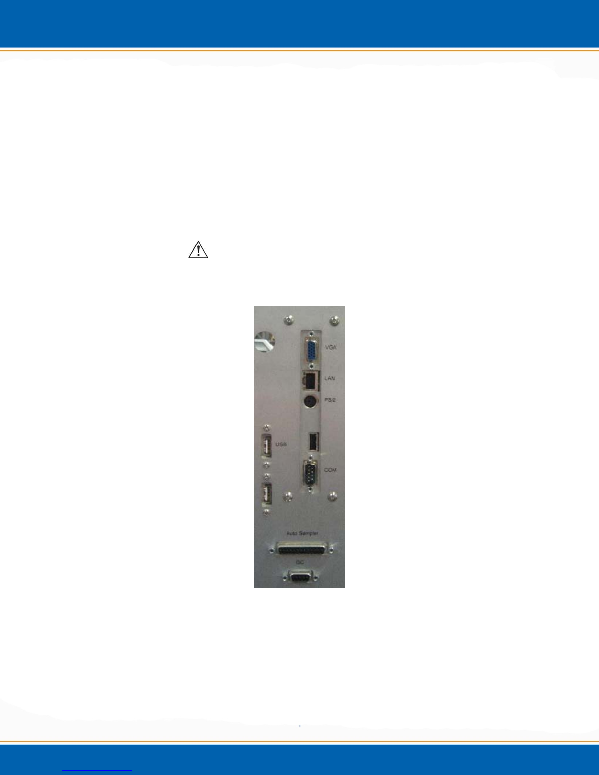
Please refer to Figure 2b for a view of the back panel of the Encon Evolution.
Figure 2b: View of the Encon Evolution’s back panel
2.5.1 Interface Connection
Install the supplied interface cable between the Encon Evolution and Gas
Chromatograph. Call EST at (800) 283-3510 or (513) 642-0100 if you have any questions
about your interface connection.
2.5.2 Monitor Connection
Mount the monitor to the post and tighten the mounting bracket to the hold down post
screw. Plug the VGA cable to the VGA port on the bottom of the monitor. Plug power
cable to the 24 VDC port on the back of the monitor. Note: If optional touch screen
monitor is purchased an additional a 9 pin cable will be included to connect to the
monitor.
2.5.3 Mouse Connection
Place the mouse on the bench and run the cable under the Encon Evolution and out the
back of the instrument. Plug the mouse into the USB connector labeled “Mouse”.
2.5.4 Gas Connections
Pressurization Gas
Connect the 1/8” helium line to the bulkhead of the
Encon Evolution and set the tank pressure between 60-80 psi (414-552kPa).
Carrier Gas
Connect the carrier gas line of the Encon Evolution to the union at the cut in carrier gas
pathway of the gas chromatograph. The heated transfer line will connect to the other end
of the cut in the carrier gas line pathway that is closest to the inlet.
WARNING: The transfer line is heated and needs to be installed so as to keep a
minimum of 10 inches between the transfer line and any adjacent cables or objects.
AVERTISSEMENT: La ligne de transfert est chauffé et doit être installé de manière
à maintenir un minimum de 25.4 cm entre la ligne de transfert et les câbles ou les
objets adjacents.
2.5.5 Power Connection
Plug power cord into the power entry module located on the back of the Encon
Evolution.
WARNING: Ensure proper grounding of the Encon Evolution system before
powering the system up.
AVERTISSEMENT: S'assurer de la bonne mise à la terre du système Encon
Evolution avant de mettre le système en place.
2.5.6 System Power Up
The Encon Evolution is ready for power cycle. Turn on the Encon Evolution and follow
the Encon Evolution Installation checklist below. The power switch is located in the rear
right side of the unit.
NOTE: EST strongly recommends you familiarize yourself with the rest of the
manual before proceeding to the installation checklist. If you have any questions
regarding installation please do not hesitate to call EST Analytical at (800) 283-3510
or (513) 642-0100, or your local authorized dealer.

User Manual
Operation
Chapter 3

3.1 Power On
1. Please read the user manual and become familiar with the operation of the Encon EV
prior to installation of the concentrator. NOTE: Only a trained operator may run
the Centurion.
1. Be sure that all electrical connections are in place and the plumbing connections are
free of gas leaks before powering on the concentrator.
2. Be sure that the pressure of the gas tank or gas line connected to the EV is between 60
and 80psi (414-552kPa), with (80psi 552kPa) being the maximum.
3. Press ON at the power switch located on the right side of the rear panel.
4. The embedded Windows XPe™ operating system will load and then the MCR relay
will load. The MCR relay is a self-loading communication device between the Encon
EV and the Windows XPeTM operating system.
3.2 Open the Encon EV Application
1. The user will control the operation of the Encon EV using the mouse provided or the
touch screen.
2. <click> Encon EV on the desktop.
3. The EST Analytical screen will appear while the application is loading.
4. When the application has loaded, the user will need to input the password in order to
log on. The default password is ESTAnalytical (case sensitive).
5. Finally, the Main screen will be displayed and the Encon EV is ready for operation.
3.3 Power Off
1. From the Main screen <click> Exit, this will close the Encon EV
application.
2. <click> Start from the taskbar.
3. Select shut down.
TM
4. After Windows XPe
off your computer.
5. Press OFF at the power switch located on the right side of the rear panel. NOTE:
Using other means to power off the Encon EV may result in damage to the
operating system.
has shut down it will prompt the user: It is now safe to turn
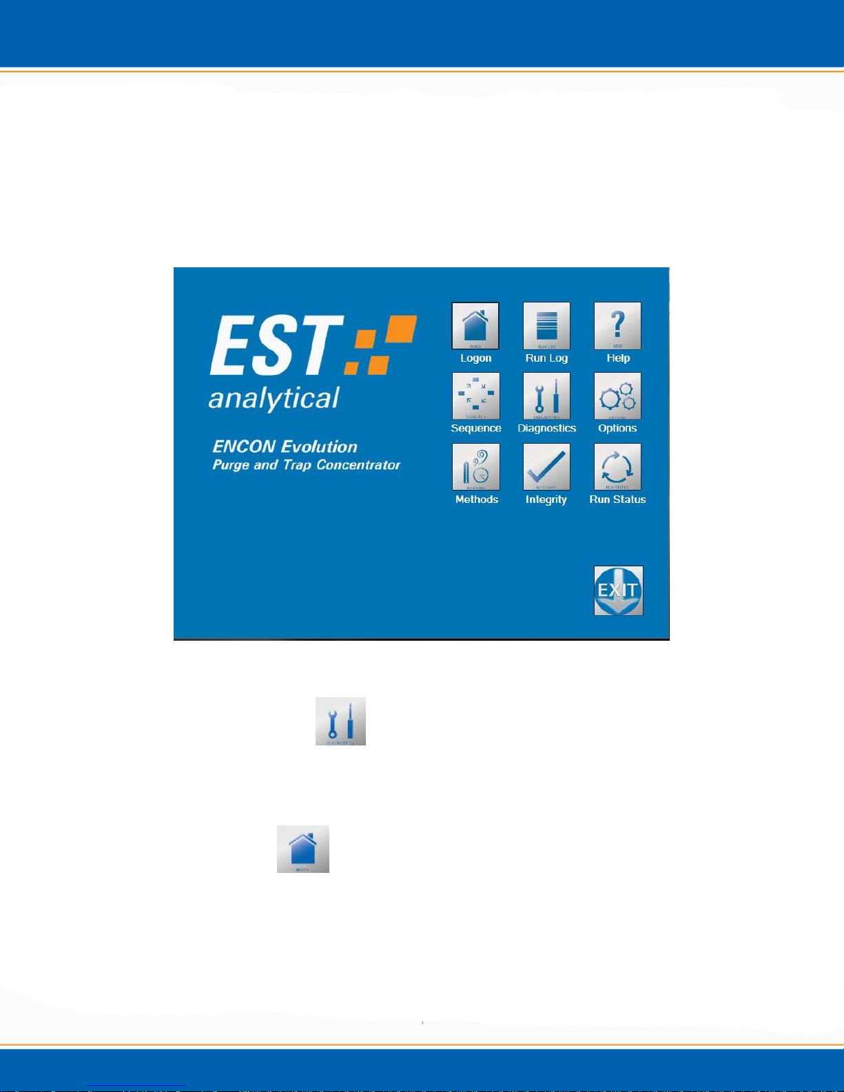
3.4 The Main Screen
The Encon EV Main screen (shown in Figure 3a) displays a series of icons which allow
the user to navigate through the application, build methods, monitor the status of the
concentrator, trouble shoot and view the status logs. After a screen has been accessed the
icons will be displayed along the left side of the screen to allow the user to simply click
on the icon to load another screen of the program.
Figure 3a: Main screen
3.5 Diagnostics Screen
Refer to Maintenance and Troubleshooting chapter #4 for the Diagnostic Screen
functions.
3.6 Home/Log On
This icon serves a dual purpose. 1) On the Main screen it serves as the user logon icon.
The logon allows for multiple users with various levels of access to the Encon EV
application. 2) To return to the Main screen from any other accessed screen, <click> on
the Home icon and the Main screen will be displayed.

3.7 Exit
The Exit icon is only displayed on the Main screen. The user cannot exit the application
without first returning to the Main screen with the Home icon. To exit the Encon EV
application, <click> Exit icon. This will drop the Encon EV application and return to the
Windows XPe
TM
desktop.
3.8 Options
The Options screen enables all instrument options. To open the Options screen, <click>
the Options icon. The Options screen will be displayed. This screen contains three tabs:
Instrument, System Setup and User Accounts.
Figure 3b: Options screen – Instrument tab
Instrument tab - <click> the Instrument tab, the screen will appear as shown in Figure
3b. This provides information specific to the Encon EV instrument.
Encon Evolution – Listed in the Encon Evolution box is the instrument name, serial
number and software version. This information is used in troubleshooting and generating
key codes for the optional hardware additions to the standard Encon EV platform.
Instrument Options – Listed in the instrument options box are the manufacturer
supplied key codes to activate hardware options.

Figure 3c: Options screen – System Setup tab
System Setup tab - <click> the System Setup tab, the screen will appear as shown in
Figure 3c. From this screen select instrument configurations and settings such as type of
trap, GC ready signal, pressure units, maximum temperatures and to set the trap
maintenance reminder.
Signal setup – The Encon EV can be interfaced to most gas chromatograph (GC)
models. The GC Ready pull down provides the various selections for ready output
signals.
TTL Low - TTL Low must be selected when interfacing with a GC which gives
a high voltage output signal when ready and a low voltage output signal when not
ready.
TTL High – TTL High must be selected when interfacing with a GC which gives
a low voltage output signal when ready and a high voltage output signal when not
ready.
CC Open – CC Open, (Contact Closure), must be selected when interfacing with
a GC which gives a contact open output signal when ready and a contact closure
output signal when not ready.

CC Closure – CC Closure must be selected when interfacing with a GC which
gives a contact closure output signal when ready and a contact open output signal
when not ready.
NOTE: Changing the signal set up settings may require a hardware jumper
change. Please contact Technical Support at 1-800-283-3510.
Gas Type – There are two gas options available from the pull down menu: Helium and
Nitrogen.
I/O Handshaking - There are two I/O Handshaking options available from the pull down
menu: Remote and Local modes.
Remote – When remote mode is selected the Encon EV will only desorb the
sample when a ready signal is received from the GC. If the Encon EV is ready to
desorb and the GC is not ready a Waiting for GC Ready message will be
displayed on the Run Status screen.
Local – When the local mode is selected the Encon EV will not wait for a ready
output signal from the GC before going into desorb.
Pressure Units – All programmable pressure settings can be expressed in units of psi or
kPa. The pressure unit selections are available from the pull down menu.
Trap Name – Using the pull down menu select the type of trap installed in the Encon
EV. The trap type will be displayed on the Run Status and Diagnostics screens.
Trap Ready Max (°C) – This is the maximum temperature value that will be accepted in
an Encon EV method to generate a purge ready signal for the analytical trap chosen. The
temperature is programmable in increments of 1°C using the up/down selection arrows.
Trap Dry Sweep Max (°C) – This is the maximum temperature value that will be
accepted in an Encon EV method for the analytical trap chosen. The temperature is
programmable in increments of 1ºC using the up/down selection arrows.
Trap Desorb Max (°C) - This is the maximum temperature value that will be accepted in
an Encon EV method for the analytical trap chosen. The temperature is programmable in
increments of 1ºC using the up/down selection arrows.
Trap Bake Max (°C) - This is the maximum temperature value that will be accepted in
an Encon EV method for the analytical trap chosen. The temperature is programmable in
increments of 1ºC using the up/down selection arrows.

Set Reminder – A reminder can be programmed to prompt the user to replace the trap on
a selected date, <click> on the check box. From the pull down, a calendar will be
displayed to allow the user to select the future date. After the date has passed a pop up
reminder box will appear when initializing the Encon EV application and every 24 hours
after the date has passed. When the pop up box appears, the user can choose to ignore
this reminder, <click> OK and proceed as usual. The pop up will keep appearing as long
as the enable reminder is set.
Install Trap – After a new trap has been installed, <click> the Install Trap button to
display the install date.
Save – To save the trap setup parameters, <click> the Save button.
Trap Back Pressure – This system pressure is determined from calibrating the purge
flow. When the desired purge flow is established from the Diagnostics screen the
pressure will be displayed in the pressure display pop-up box. This figure must be
manually added to the Trap Back Pressure field.
Figure 3d: Options screen – User Accounts tab
User Accounts - <click> the User Accounts tab, the screen will appear as
shown in Figure 3d. This tab provides the current user logon information
including date, time and duration.
Add – This selection allows for the addition of Encon EV users.
Remove – This selection allows for the removal of Encon EV users.

Properties – This selection allows for the level of access to a specific user. The user(s)
will be identified and set up by the authorized Field Service Engineer during the Encon
EV installation.
3.9 Sequence Screen
The Sequence screen provides the ability to analyze batches of samples using different
Encon EV methods. <click> the Sequence icon, the screen will appear as shown in
Figure 3e.
Line – Ten sequence lines are available for sample analysis by different Encon EV
methods. Ten different methods can be linked together to create a sequence.
Description – User supplied description names.
Method – The drop down lets the user select from the available methods.
Number of samples – The number of samples analyzed per method.
Printing a Sequence -
NOTE: To print, a printer must be interfaced with the Encon EV.
Figure 3e: Sequence screen
<click> on the Printer icon.

Saving a Sequence - <click> on the Save icon and the sequence will be saved.
Open a Saved Sequence - <click> on the Open icon and all previously saved
sequences are available to be loaded.
3.10 Method Screen
The Method screen contains the settings and conditions necessary to create an Encon EV
purge and trap method. <click> the Method screen icon, the Method screen will be
displayed as shown in Figure 3f. Every Encon EV Method screen will consist of two
tabs: Method Setup and Purge & Trap. Each additional option to the Encon EV will
have its own specific tab.
Figure 3f: Method screen – Method Setup tab
3.10.1 Method Setup tab - <click> the Method Setup tab, the screen will appear as
shown in figure 3f. This tab contains the parameters for the operation of the
concentrator.
Overfill – (OPTION, Included with Foam Detector) – In purge ready status, if the sample
failed to drain from the prior run, the Overfill will protect against flooding the Encon EV
with sample. If Overfill is detected, a note will be made in the Run Log.

Foam Sensor – (OPTION) – If selected, during purge a fiber optic beam monitors for
foam in the glassware. If a foamed sample is detected the sample will be drained; the GC
will be sent a start signal to perform a blank run, ensuring the GCs sequence table is
accurate. The sample pathway is then baked out and a notification is written to the
instrument’s sample log.
Automatic Leak Check – This feature provides the ability to leak check the concentrator
prior to beginning a method run. This is a separate function from the manual leak check
(Refer to the Troubleshooting section for manual leak check).
Off – Select Off and the leak check is disabled.
On – Select On and the Encon EV will perform a leak check each time the
concentrator steps from standby status and prior to Ready status.
First Pass – Select this option and the Encon EV will perform a leak check each time a
new sequence line is loaded
GC Cycle Time (min) – This is the time in minutes between the start of a sample desorb
and the time the GC is ready for the next desorb cycle from the Encon EV. This value is
equal to or greater than the sum of the total GC analytical run plus the GC cool down
time and equilibration time. The GC Cycle Time can be set to a value of 0.0 - 999.9
minutes using the up/down selection arrows. Note: The GC cycle time is used when the
GC run time is longer than the purge and trap cycle time or when utilizing the dual
concentrator option of the Encon Evolution system.
Start Delay (min) – This is the time in minutes that the Encon EV will wait until sending
out a ready signal. The start delay time can be set to a value of 0.0 - 999.9 minutes using
the up/down selection arrows.
Economy Mode - During idle instrument time the Encon EV can remain powered on and
programmed to conserve energy and gas. To display the Economy Mode, <click> the
Program button. A screen will be displayed as shown in Figure 3g. Enable the desired
Saver mode(s). Enter the Initiate Time (time after the system becomes ready in which
you wish to enter this mode) in minutes. Enter the reduced Gas Flow if the Gas Saver is
enabled. Once the elapsed initiate time is reached the Economy Mode will go into effect
and the flow will be reduced to the set point and/or the heaters will be disabled. A
caution box will be displayed indicating the Economy Mode is active. To deactivate the
Economy Mode and return to the Standby mode, <click> OK. The Encon EV will
remain in standby until the heated zones reach the set points.

Figure 3g: Economy Mode screen
Standby Flow (ml/min) – The rate at which the gas flows through the sample pathway
while the instrument is in standby and purge ready. This parameter is off (no standby
flow) or on with a programmed value of 0 – 500ml/min using the up/down selection
arrows.
Automatic Drain Sparge Vessel – Select On and the Encon EV will drain the sample
from the sparge tube at desorb. Select Off and the Encon EV will not drain the sample
from the sparge tube.
NOTE: If the drain function is off and the Encon EV has the Sample Heater
option installed and turned on, the sample must be manually drained at desorb.
Bake Gas Bypass – Select Off and during bake the gas flow pathway will be through the
sparge tube. Select On and during bake the gas flow pathway will be diverted and not
flow through the sparge tube.
Transfer Line Temperature (°C) – This is the temperature of the transfer line which
connects the Encon EV to the GC Inlet. This parameter can be set to a temperature
between 35°C and 350°C in 1°C increments using the up/down selection arrows
Valve Oven Temperature (°C) – This is the temperature of the oven which contains the
8 port rotary valve and sample pathway tubing. This parameter can be set to a
temperature between 35°C and 350°C in 1°C increments using the up/down arrows.
Auto Sample Prep Time (min) – When connected to an autosampler, the Encon EV can
be programmed to send out a decoy ready signal to the autosampler to begin the sampling
process before the concentrator reaches the purge ready status and sends out the true
ready signal to the autosampler. This is useful with syringe style auto samplers where it
may take several minutes to complete the transfer of sample from the autosampler to the
Encon EV. This can reduce overall cycle by the time it takes the autosampler to process a
sample.

Mount Temperature (°C) – (OPTION) – This is the temperature of the sample mount.
This parameter can be set to a temperature between 35°C and 100°C in 1°C increments
using the up/down arrows.
Auxiliary Temperature (°C) – (OPTION) – This is the temperature of the auxiliary
heater. This parameter can be set to a temperature between 35°C and 350°C in 1°C
increments using the up/down arrows.
Figure 3h: Method screen – Purge & Trap tab
3.10.2 Purge & Trap tab - <click> the Purge & Trap tab. The screen will appear as shown in
Figure 3h. This tab contains the parameters for the operation of the concentrator in its
various modes: ready, purge, dry purge, desorb and bake.
Trap Ready Temperature (°C) – This is the temperature the adsorbent trap must reach
before going to purge ready status. The adsorbent trap will continue to cool (free fall)
after reaching the set point. The adsorbent trap ready temperature can be programmed to
a value of 25°C to the maximum set point, in 1°C increments.
MoRT Ready Temperature (°C) – This is the temperature the MoRT (Moisture
Reduction Trap) trap must reach before going to purge ready status. When the MoRT
tube temperature is set to 40°C or above the Encon EV will maintain that temperature. If
the temperature is set below 40°C the MoRT tube will continue to cool (free fall) after
reaching the set point. The MoRT tube ready temperature can be programmed to a value
of 25°C to the maximum set point, in 1°C increments.

Purge Flow Rate (ml/min) – This setting is the rate at which the purge gas is
programmed to flow through the sample pathway during purge. The purge flow rate can
be programmed from 1 to 500mL/min in 1mL/min increments.
Programmable Purge Flow Control - <click> the Program button to enable this
feature. This feature can be used to change purge flow rates during the purge cycle. The
screen will appear as shown in Figure 3i. Check the Enable Ramp Control box to
program the desired settings.
Initial Flow (ml/min) – This is the beginning purge flow rate programmed in
ml/min. The initial flow can be programmed from 0 to 500ml/min in 1ml/min
increments.
Initial Hold Time (min) – This is the time in minutes the initial flow is
maintained. The initial hold time can be programmed from 0 to 99.9 minutes in
0.1 minute increments.
Ramp Rate ((ml/min)/min) – This is the rate programmed in ml/min, the purge
flow will increase after the initial hold time has expired to the desired final flow
set point. The ramp rate can be programmed from 1ml/min to 500ml/min in
1ml/min increments.
Final Flow (ml/min) – This is the ending purge flow rate programmed in ml/min.
The final flow can be programmed from 0 to 500ml/min in 1ml/min increments.
Once the desired options are selected, <click> the Exit button to return to the
method parameters page.
Figure 3i: Programmable Purge Flow Control

Final Hold Time (min) – This is not a programmable setting but a function of the
set conditions. The final hold time will be the difference of the final purge time
from the sum of the initial time and the time needed to achieve the final flow rate.
For Example: Total Purge Time = 4 minutes
Initial Flow = 40ml/min
Initial Hold Time = 0.5 minutes
Ramp Rate = 40ml/min per minute
Final Flow = 200ml/min
The Final Hold time at 200ml/min would be 0.5 minutes.
Explanation: It takes 4 minutes to ramp from 40ml/min to 200ml/min at a
rate of 40ml/min per minute. The final hold time is calculated to be 0.5
minutes.
4 minutes – (0.5 minutes + 3 minutes) = 0.5 minutes
Purge Time (min) – This is the length of time for the sample purge. The purge time can
programmed from 0.0 to 999.9 minutes.
Trap Dry Purge Temperature (°C) – This is the temperature of the adsorbent trap
during dry purge. The temperature can be programmed from 25°C to the set point in 1°C
increments.
NOTE: This temperature should be set to below ambient to eliminate the possibility
of analyte migration within the trap prior to desorb.
Dry Purge Flow Rate (ml/min) – This is the rate the pressurization gas flows through
the adsorbent trap during the dry purge process. The Dry Purge Flow Rate can be
programmed from 1 to 500ml/min in 1ml/min increments.
Programmable Dry Purge Flow Control - <click> the Program button to enable this
feature. This feature can be used to change dry purge flow rates during the dry purge
cycle. The screen as shown in Figure 3j will appear. Check the Enable Ramp Control
box to program the desired settings.
Initial Flow (ml/min) – This is the beginning dry purge flow rate programmed in
ml/min. The initial flow can be programmed from 0 to 500ml/min in 1ml/min
increments.
Initial Hold Time (min) – This is the time in minutes the initial flow is
maintained. The initial hold time can be programmed from 0.0 to 999.9 minutes.
Ramp Rate ((ml/min)/min) – This is the rate programmed in ml/min per minute
the dry purge flow will increase after the initial hold time has expired to the
desired final flow set point. The ramp rate can be programmed from 1ml/min to
500ml/min in 1ml/min per minute increments.

Final Flow (ml/min) – This is the ending dry purge flow rate programmed in
ml/min. The final flow can be programmed from 0 to 500ml/min in 1ml/min
increments.
Once the desired options are selected, <click> the Exit button to return to the
Method Screen.
Figure 3j: Programmable Dry Purge Parameters
Final Hold Time (min) – The final hold time will be the difference of the final
dry purge time from the sum of the initial time and the time needed to achieve the
final flow rate.
For Example: Total Dry Purge Time = 5 minutes
Initial Flow = 40ml/min
Initial Hold Time = 0.5 minutes
Ramp Rate = 40ml/min per minute
Final Flow = 200ml/min
The Final Hold time at 200ml/min would be 0.5 minutes.
Explanation: It takes 4 minutes to ramp from 40ml/min to 200ml/min at a
rate of 40ml/min per minute. The final hold time is calculated to be 0.5
minutes.
5 minutes – (0.5 minutes + 4 minutes) = 0.5 minutes
Dry Purge Time (min) – This is the total length of time for dry purge. The dry purge
time can be programmed from 0.0 to 999.9 minutes.
Desorb Pressure Control (psi/kPa) – This pressure setting enables the Encon EV to
equilibrate the concentrator system pressure to that of the GC head pressure prior to
desorb preheat.

Desorb Flow Control (psi/kPa) – DFC is an enhanced feature of EST Analytical’s water
management system. It provides for lower flow through the trap during desorb while
maintaining higher split ratios at the GC inlet. Setpoint is tied to EV pressure and must
be above the initial column head pressure to increase split flow.
Desorb Preheat Temperature (°C) – This is the temperature the adsorbent trap is heated
to before the GC carrier gas is directed to the adsorbent trap to back flush and transfer the
analytes to the GC inlet. This temperature can be programmed from 25°C to the set point
in 1°C increments
Desorb Temperature (°C) – This is the temperature the adsorbent trap maintains during
the desorb process. The temperature can be programmed from 25°C to the set point in
1°C increments.
Desorb Time (min) – This is the total amount of time the GC carrier gas is in line with
the adsorbent trap to sweep the analytes to the GC inlet. The trap desorb time can be
programmed from 0.0 to 999.9 minutes. The Encon EV will send out a start signal to the
GC as soon as desorb starts.
Trap Bake Temperature (°C) – This is the set point temperature of the adsorbent trap
during bake. The trap bake temperature can be programmed from 35°C to the set point in
1°C degree increments.
Programmable Trap Bake Temperature - <click> the Program button to enable this
feature. The screen as shown in Figure 3k will appear. <Check > the Enable Ramp
Control box to program the desired settings.
Initial Temperature (°C) – This is the beginning temperature programmed in °C.
The temperature can be programmed from 25°C to the set point in 1°C
increments.
Initial Hold Time (min) – This is the time in minutes the initial temperature is
maintained. The initial hold time can be programmed from 0.0 to 999.9 minutes.
Ramp Rate ((°C/min)/min) – This is the rate programmed in °C/min per minute
the bake temperature will increase after the initial hold time has expired to the
desired final temperature set point. The temperature can be programmed in
1°C/min to the final temperature set point 1°C/min increments.
Final Temperature (°C) – This is the ending temperature programmed in °C.
The temperature can be programmed from 35°C to the recommended bake
temperature in 1°C increments.
Final Hold Time (min) – The final hold time is not a value to be entered by the
User. The final hold time is the calculated difference of the final bake time taken
from the sum of the initial time and the ramping time needed to achieve the final
temperature.

For Example: Total Bake Time = 10 minutes
Initial Temperature = 200°C
Initial Hold Time = 2 minutes
Ramp Rate = 10°C/min per minute
Final Temperature = 260°C
Final Hold time = 2 minutes.
Explanation: Since it takes 6 minutes to ramp from 200°C to 260°C at a
rate of 10°C/min per minute. The final hold time is calculated to be 2
minutes.
10 minutes – (2 minutes + 6 minutes) = 2 minutes
Once the desired options are selected, <click> the Exit button to return to the Method
Screen.
MoRT Bake Temperature (°C) - This is the set point temperature of the MoRT tube
during bake. The MoRT bake temperature can be programmed from 35°C to the set
point in 1°C increments.
Programmable MoRT Bake Temperature - <click> the Program button to enable this
feature. The screen as shown in Figure 3l will appear. <Check > the Enable Ramp
Control box to program the desired settings.
Figure 3k: Programmable Trap Bake Temperature Control
Initial Temperature (°C) – This is the beginning temperature programmed in
°C. The temperature can be programmed from 25°C to the set point in 1°C
increments.
Initial Hold Time (min) – This is the time in minutes the initial temperature is
maintained. The initial hold time can be programmed from 0.0 to 999.9 minutes.

Ramp Rate ((°C/min)/min) – This is the rate programmed in °C/min per minute
the bake temperature will increase after the initial hold time has expired to the
desired final temperature set point. The temperature can be programmed in
1°C/min to the final temperature set point 1°C/min increments.
Final Temperature (°C) – This is the ending temperature programmed in °C.
The temperature can be programmed from 35°C to the recommended bake
temperature in 1°C increments.
Final Hold Time (min) – The final hold time is not a value to be entered by the
User. The final hold time is the calculated difference of the final bake time taken
from the sum of the initial time and the ramping time needed to achieve the final
temperature.
For Example: Total Bake Time = 10 minutes
Initial Temperature = 200°C
Initial Hold Time = 2 minutes
Ramp Rate = 10°C/min per minute
Final Temperature = 260°C
Final Hold time = 2 minutes.
Explanation: Since it takes 6 minutes to ramp from 200°C to 260°C at a
rate of 10°C/min per minute. The final hold time is calculated to be 2
minutes.
10 minutes – (2 minutes + 6 minutes) = 2 minutes
Once the desired options are selected, <click> the Exit button to return to the
Method Screen.
Figure 3l: Programmable MoRT Trap Bake Temperature Control

Bake Flow Rate (ml/min) – This is the flow rate of the pressurization gas during the
bake cycle. The bake flow rate can be programmed from 0 to 500ml/min in 1ml/min
increments.
NOTE: It is suggested to have a minimum a flow rate of at least 10ml/min
passing through the trap when the trap temperature is above ambient. This will
prevent damage to the trap material.
Programmable Bake Flow Control - <click> the Program button to enable this feature.
The screen as shown in Figure 3m will appear. <Check > the Enable Ramp Control
box to program the desired settings.
Initial Flow (ml/min) – This the beginning bake flow rate programmed in
ml/min. The initial flow can be programmed from 0 to 500ml/min in 1ml/min
increments.
Initial Hold Time (min) – This is the time in minutes the initial flow is
maintained. The initial hold time can be programmed from 0.0 to 999.9 minutes.
Ramp Rate ((ml/min)/min) – This is the rate programmed in ml/min the bake
flow will increase after the initial hold time has expired to the desired final flow
set point. The ramp rate can be programmed from 1 ml/min per minute to 500
ml/min 1 ml/min increments.
Final Flow (ml/min) – This is the ending bake flow rate programmed in ml/min.
The final flow can be programmed from 0 to 500ml/min in 1ml/min increments.
Final Hold Time (min) – The final hold time is not a value to be entered by the
User. The final hold time is the calculated difference of the final bake time taken
from the sum of the initial time and the ramping time needed to achieve the final
flow rate.
For Example: Total Bake Time = 10 minutes
Initial Flow = 40ml/min
Initial Hold Time = 2 minutes
Ramp Rate = 40ml/min per minute
Final Flow = 240ml/min
Final Hold time = 3 minutes.
Explanation: Since it takes 5 minutes to ramp from 40ml/min to
240ml/min at a rate of 40ml/min per minute. The final hold time is
calculated to be 3 minutes.
10 minutes – (2 minutes + 5 minutes) = 3 minutes

Figure 3m: Programmable Bake Flow Control
Once the desired options are selected, <click> the Exit button to return to the
method parameters screen.
Bake Time (min) – This is the total length of time for one bake cycle. The bake time can
programmed from 0.0 to 999.9 minutes.
Bake Cycles – The number of bake cycles for one sample analysis. This can be
programmed from 1 to 10 cycles. After the first bake cycle is completed the trap and
MoRT will cool to approximately 60°C before beginning to heat for the next bake cycle.
Printing the Method - <click> on the Printer icon. The method can be printed if
the Encon EV is interfaced to a printer
Saving the Method -
<click> on the Save icon and the method will be saved.
NOTE: After saving a method, it must be opened to activate.
Open a Saved Method - <click> on the Open icon and all previously saved
Methods are available to be loaded.

Figure 3n: Method screen – Sample Heater tab
3.10.3 Sample Heater tab (Option) – If this Option is installed <click> on the Sam ple
Heater tab. The screen will appear as shown in Figure 3n. This tab contains the
parameters for the operation of the sample sparge tube heater. The sample heater
comes on at desorb and through the bake cycle to reduce carryover from run to
run.
Sample Heater Type – Select On and the heater will be active during the bake
cycle. Select Off and the heater will be inactive during the bake cycle.
Pre Purge Time (min) – The amount of time that the sample is purged with
pressurization gas before the pre heat function begins.
Preheat Temperature (°C) – The temperature applied to the sample in the sparge
tube prior to purge.
Preheat Time (min) – The duration of time, in minutes, that heat will be applied
to the sample in the sparge tube prior to purge.
Purge Temperature (°C) – The temperature applied to the sample in the sparge
tube during purge.
Bake Temperature (°C) – The temperature applied to the sparge tube during
bake.

3.11 Run Status Screen
The Run Status screen contains all the information needed to monitor the Encon EV
during the purge and trap process. <click> on the Run Status screen icon. The Run
Status screen will be displayed as shown in Figure 3o.
Figure 3o: Run Status screen
The Run Status screen displays the current Encon EV instrument settings for real time
monitoring of the concentrator and contains the buttons necessary to apply the Step To,
Start / Stop and Hold functions.
Step To – The Step To button will display the following functions:
Standby
Purge Ready
Purge
Dry Purge
Desorb Ready
Desorb Preheat
Desorb
Bake
Step to Standby With Drain
Step to Bake With Drain

These function keys allows the user to navigate through the entire purge and trap process.
By selecting a step to the desired task the Encon EV will override the current function
that the concentrator is engaged in and proceed to that choice.
Start / Stop –This is a dual function button. <click> the Start button and the Encon EV
will begin the selected P&T method. <click> the Stop button and the P&T method will
be stopped.
Hold – <click> the Hold button and the Encon EV will remain in the mode that it is
currently engaged. A timer will show on the Run Status screen displaying the elapsed
hold time. Also displayed will be the remaining time of the process that is in hold. The
concentrator will remain in hold until the Hold button is clicked again.
Current Run Status and Time Counter – This displays the current status of the Encon
EV and the remaining time of the current function.
Position of 8 Port Valve – The position of the 8 port valve is displayed and the
corresponding flow pathway is shown.
GC Ready / Not Ready – In the upper left corner of the Status screen is an icon of a GC.
When the GC is outlined in green it is ready. When the GC is outlined in red it is not
ready.
Temperatures (°C) – Displayed on the Run Status screen are the actual temperatures of
the absorbent trap, MoRT tube, transfer line, 8 port valve, sample heater and mount.
Pressure (psi or kPa) – Displayed on the Run Status screen are the actual system
pressures in the form of a value and a bar graph.
Flow (ml/min) – Displayed on the Run Status screen are the actual system flows in the
form of a value and a bar graph.
Current Flow Pathway – Displayed on the Run Status screen is the general flow
pathway.
3.12 Active Run Log
The active run log is an automatically updated listing of Encon EV functions performed.
This log will be generated until the Encon EV application is closed. Opening the Encon
EV application will begin a new active run log. The active run can be saved if desired.
The Active Run Log screen will be displayed as shown in Figure 3p.

Printing the Run Log – <click> the Printer icon. The Error Log can be printed if
the Encon EV is interfaced to a printer.
Saving the Run Log – <click> the Save icon. The Error Log can be saved.
Opening a saved Run Log –
logs are available to be viewed.
3.13 Reports Page
Printing the Error Log– <click> the Printer icon. The Error Log can be printed if
the Encon EV is interfaced to a printer.
Figure 3p: Active Run Log screen
<click> the Open icon. All previously saved Error
Saving the Error Log –
Opening a saved Error Log – <click> the Open icon. All previously saved Error
Logs are available to open.
<click> the Save icon. The Error Log can be saved.

3.14 Integrity
This icon is reserved for a feature that may be issued in a future release.
3.15 Help Screen
By placing the cursor and clicking on the Help icon the Help screen will appear as shown
in Figure 3q. The Help screen provides the ability to view help files that are stored
locally on the Encon EV software.
Encon Evolution User Manual – By placing the cursor and clicking on ENCON EV
User Manual the user can view a PDF version of the operation manual.
Encon Evolution Software Update – By placing the cursor and clicking on HOW TO –
Encon Evolution Updates the user can view the instructions to update the Encon
Evolution software.
Encon Evolution Printer Installation – By placing the cursor and clicking on HOW TO
– Encon EV Printer Installation the user can view the printer installation instructions.
Figure 3q: Help Screen

HOW TO - Encon Evolution Update.
The Encon EV update file will either be a ZIP archive or a self-extracting EXE archive.
Encon EV updates may be accomplished through either of the two available USB ports
and a USB memory stick.
ZIP Archive
1. Transfer Encon EV update to USB memory stick from desktop or laptop
computer.
2. Extract zip file on USB memory stick. Extraction will create a folder named
Encon EV Update containing all update files which require transfer to the
instrument.
3. Remove memory stick from computer and insert into USB port on instrument.
4. Open file ReadMeFirst.txt inside Encon EV Update folder and follow instructions
for transfer of applicable update files to instrument.
5. When transfer of update files are complete, open My Computer, right click on
Removable Drive and select Eject.
6. Remove memory stick from USB port on instrument. Encon EV update is now
complete.
EXE Archive
1. Transfer Encon EV update to USB memory stick from desktop or laptop
computer.
2. Remove memory stick from computer and insert into USB port on instrument.
3. Double click on EXE file to start update process. Update process is complete
when a dialog box appears stating Encon EV Updates Complete.
4. Acknowledge dialog box by selecting OK.
5. When transfer of update files are complete, open My Computer, right click on
Removable Drive and select Eject.
6. Remove memory stick from USB port on instrument. Encon EV update is now
complete.

3.16 Recommended Encon Evolution Purge & Trap Parameters
USEPA Method 8260B
Valve Temperature 150oC
Transfer Line Temperature 150oC
Automatic Drain Sparge Vessel On
Bake Gas Bypass Off
Standby Flow Rate On @ 40ml/min
Trap Ready Temperature 35oC
MoRT Ready Temperature 39oC
Purge Flow Rate 40ml/min
Purge Flow Time 11 minutes
Dry purge Temperature Off
Dry purge flow rate 40ml/min
Dry Purge Flow Time 1 minute
Desorb Pressure Control On 5.0 (Note: Set to 1 to 2psi below the inlet head
pressure, no more than 10psi)
Desorb Flow Control Off
Desorb Preheat Temperature 245oC
Desorb Temperature 250oC
Desorb Time 0.5 minutes
Trap bake temperature 260oC
MoRT Bake Temperature 210oC
Trap Bake Flow 85ml/min = 5ml purge volume
30ml/min = 25ml purge volume
Trap Bake Time 6 minutes
Trap Bake Cycles 1
Purge Temperature (option) Off
Sparge Bake Temperature (option) On – Program: 40oC initial, hold for 3 minutes, ramp at
o
C/min to 110oC final temperature
100
Trap Back Pressure Equal to pressure at 40ml/min purge flow
TRAP DESORB, BAKE, AND CONDITION TEMPS (FROM SUPELCO).

User Manual
Maintenance and Troubleshooting
Chapter 4

This chapter contains information necessary to maintain and/or
troubleshoot the EST Analytical Encon Evolution.
The purpose of this Chapter is to familiarize the user with the various integrated maintenance
and troubleshooting functions of the Encon Evolution.
The Encon Evolution will require minimal maintenance of consumable items such as, tubing,
traps, septa, Teflon ferrules, power cord, etc. The interval at which maintenance is required
depends on use and sample types.
In order to maintain the safety integrity provided by the instrument for parts containing liquids,
during maintenance, ONLY use replacement parts provided by EST Analytical.
CAUTION: Before Maintaining and Servicing any component of the Encon
Evolution the instrument must be:
1. Turned off (Note: Windows should be turned off properly.)
2. Disconnected from the Power Supply
3. Hot Surfaces should be given time to cool
4. After servicing instrument, all covers need to be placed back on the instrument.
ATTENTION: Avant de maintenance et d'entretien tout composant de
l'évolution Encon l'instrument doit être:
1. Désactivé (Note: Windows doit être désactivé correctement)
2. Déconnecté de l'alimentation
3. Surfaces chaudes devraient avoir le temps de refroidir
4. Après instrument entretien, tous les couvercles doivent être placés sur
l'instrument.

4.1 Technical Support
To ask technical questions or to obtain technical services please contact EST Analytical:
Within the United States and Canada call toll free: (800) 283-3510.
Outside of the United States and Canada call: Regional Authorized Distributor.
Before calling for technical assistance or onsite service:
Note the serial number of the instrument. (The serial number can be located in the
Option Screen under the Instrument tab or on the back of the unit.)
Note the type of problem you are experiencing and the conditions under which the
problem occurred.
Note the exact wording of the error message (if applicable).
Please have the compact disc manual open and available.
4.2 Cleaning the Encon Evolution
1. Wipe the outside of the Encon Evolution with a clean, damp, lint-free cloth. Cloth
should be dampened with water only. Avoid any cleaning agents that could cause a
hazard as a result of a reaction with parts of the equipment of with the material
contained in it.
2. Use canned air to remove any dust or lint from the fans or inside the unit.
4.3 Trap/MoRT Replacement
1. CAUTION: Make certain the instrument is not running and the trap is cool.
ATTENTION: Assurez-vous que l'instrument n'est pas en cours d'exécution et
le piège est cool.
2. Remove trap MoRT cover(s) on the front of the Encon Evolution. When facing the
EV, the adsorbent trap in on the right and the MoRT is on the left.
Note: Instrument cover/wrap and front panel must be removed for units with a serial
number less than EV252051410.
3. Loosen the nut from the top of trap fitting and the nut from the bottom of trap.
4. Remove the trap insert from the trap heater sleeve coils.
5. Install the new trap by repeating the above steps in reverse order.

6. Verify the Encon Evolution is free of leaks by performing a Leak Check routine
discussed later in this Chapter.
7. Condition the new trap by performing the single button ‘Trap Bake’ routine discussed
later in this Chapter. Please use recommended conditions outlined by the trap
manufacturer. These conditions are included with the new trap.
8. Update the ‘Install Trap’ function in the ‘Options’ page of the Encon Evolution
program and set the reminder to the next scheduled replacement. Refer to the
Operations Chapter for further instructions.
NOTE: Be sure the analytical trap is installed properly with the markings and the
pre-swaged ferrule at the top.
4.4 Diagnostics Screen
<click> the Diagnostics screen icon. The Diagnostics screen will be displayed as shown
in Figure 4a. The Diagnostics screen contains the settings and controls necessary to
manually operate and trouble shoot the Encon EV. It enables the user to leak and flow
check the concentrator. It also displays the various flow pathways. Other functions
include manual activation of the solenoid valves and manual temperature control of the
heated zones.
Figure 4a: Diagnostics screen

4.4.1 Icons
8 Port Valve icon - The 8 port valve can be manually actuated. <click> the 8 Port
Valve icon. When actuated, the flow pathway will change indicating which ports are
connected at that given position. Position A is the sample pathway and Position B is the
desorb pathway.
GC icon - In the upper left corner of the Diagnostics screen is an image of a GC. When
the image is outlined in green the GC is sending out a ready signal. When the image is
outlined in red the GC is sending a not ready signal.
Trap icon - Displays the trap type installed. <click> the Trap icon and the Options
screen will open to the System Setup tab. To return to the Diagnostic screen, <click> the
Diagnostic screen icon.
Sparge Vessel icon - <click> the Sparge Vessel icon and the Pressurization Valve PID
calibration screen will open as shown if Figure 4b.
Figure 4b: Pressurization Valve PID Calibration Screen
Pressure Transducer – The current Encon EV system pressure is displayed in this box.
Current flow – The current Encon EV flow is displayed in this box.

4.4.2 Manual Heater Control
The heated zones, which consist of the Trap, MoRT, Sample (option), Mount (option),
Transfer Line and Valve Oven may be manually heated to a specific set point
temperature. <click> the temperature display box located next to the respective icon for
any given heated zone and the manual temperature control will appear as shown in Figure
4c.
NOTE: The system continuously monitors for over temperature conditions and will
provide a pop-up screen to alert of any over temperature problems.
Figure 4c: Setpoint Temperature screen (Sample Heater)
Current Temperature (°C) – Displays the current temperature.
Setpoint (°C) – Enter the desired set point (SP) temperature.
Heat to SP - <click> the Heat to SP button. The selected zone will heat to the entered
set point. The temperature will be maintained as selected until it is manually changed
again or a method is loaded.
CAUTION: Heating the trap or MoRT tube without flow may damage the trap
sorbent materials or the MoRT tube Silco treated surface.
ATTENTION: Le chauffage du piège ou MoRT tube sans écoulement peut
endommager les matériaux absorbants piège ou le tube MoRT Silco surface traitée.
CAUTION: Manual heating will not recognize maximum temperature set points
(see Operations chapter, Options screen, System Settings tab.)
ATTENTION: chauffage manuel ne reconnaît pas les points de consigne de
température maximale (voir chapitre des opérations, l'écran Options, onglet
Paramètres système.)

4.4.3 Manual Valve Control
NOTE: There are five solenoid valves on a single manifold and six solenoid valves
on a dual manifold system.
Five solenoid valves can be activated from the diagnostic screen. <click> the Flow
(Pressurization) (#1), the Dry Purge (#2), the Vent (#3), the Backflush (#4) and the
Bake (#6) valve(s) to energize or de-energize. If energized, the valve is outlined in red
and the gas flow will follow the appropriate pathway. A de-energized valve will not be
outlined in red and the gas will follow the appropriate pathway. <click> the valve again
to de-energize or energize. The valve(s) will stay in the selected position until manually
changed or a method or a new flow pathway is loaded. NOTE: When de-energized the
valves are normally closed, when energized they are open.
<click> the Flow (pressurization) valve icon and the pressurization valve screen will be
displayed as in shown in Figure 4d.
Figure 4d: Pressurization Valve manual setpoint screen.
Current Flow (ml/min) – Displays the current flow.
Setpoint (ml/min) – Enter the desired flow.
Flow to SP - <click> the Flow to SP button, this will activate the flow to the set point.
The flow will be maintained as selected until it is manually changed again or a method is
loaded.
Exit - <click> Exit to return to the Diagnostic screen.
4.4.4 Flow Pathway Drop Down Menu
Located at the upper right corner, the flow pathway drop down lists the flow pathway
diagrams for standby, purge, dry purge, desorb ready, desorb and bake, as shown in
Figure 4e. Select a pathway and <click>. The appropriate valve(s) will be energized
(outlined in red) and if required the 8 port valve will rotate to the correct position.
NOTE: If a run is in progress the solenoid valve(s) and the 8 port valve will not
change away from the current pathway.

Figure 4e: Diagnostics Screen with Drop Down Menu
4.4.5 Flow
<click> the Flow button. This will open the leak check and pressure check features.
NOTE: It is recommended performing a leak check before proceeding with a flow
check.
NOTE: Flow diagrams of the Leak Check procedure are displayed in Chapter 5,
Figures 5.9 and 5.10.
Leak Check
<click> Leak Check and the process will begin.
1. The concentrator will pressurize to 20psi and then hold for 30 seconds.
+
2. If the concentrator maintains the pressure (
3. If the concentrator fails to reach or maintain the set point the 8 port valve will actuate
and the concentrator will begin a secondary leak check.
/-0.5psi) the leak check passes.
4. Upon completion of the secondary leak check a pop up window will direct the user to
the Log screen to determine the results of the leak check.

If the Leak Check fails, refer to the Leak Check Flow Diagram within this manual
or contact EST- Technical Support at (800) 283-3510 or (513) 642-0111 or your local
authorized service representative.
Flow Check
This check uses the purge flow set in the method parameters. <click> Flow Check and
the process will begin.
1. Use a flow meter to determine the purge flow out of the vent bulkhead on the front of
the unit.
2. If the flow is within +/- 2.0ml/min of the purge flow, <click> Yes and the flow check
passes.
3. If the flow is +/- > 2.0ml/min of the purge flow, <click> No* and the next pop up will
ask if the flow is +/- 5.0 ml/min of the set point.
4. If the flow is within > 5.0ml/min of the purge flow, <click> No* and the flow check
fails. Check for leaks and/or restrictions.
5. If the flow is within <5.0ml/min of the purge flow,<click> Yes and the flow check
will automatically advance to the flow calibration process. See section 4.4.6.
* If the flow is outside of the +/- 2.0ml/min window, the default user does not have
access past step 4.

4.4.6 Flow Calibration
Before performing a flow calibration, the Evolution must pass leak check. After
verifying that the Evolution is leak free, a flow calibration can be done. <click>
Calibration Flow Calibration Instrument Flow. After accessing flow calibration,
see Figure 4f, follow the instructions given. Connect a flow meter to the vent bulkhead.
Choose the calibration flow to be calibrated. Adjust the up/down output arrows so that
the actual flow from the vent bulkhead is the same as the calibration flow point. Save the
calibration. Repeat this process for every calibration flow point to be adjusted. Exit
Flow Calibration and Step to Standby.
4.4.7 Trap bake
This function enables a manual bake of the trap and/or MoRT tube. The sparge vessel
heater (option) will not heat during this process. <click> on Trap Bake. The Manual
Trap Bake screen will appear as shown in Figure 4g.
Figure 4f: Flow Calibration Screen

Figure 4g: Manual trap bake screen.
Bake Time (min) – Set the bake time from 0.0 to 999.9 minutes.
Bake Cycles – Set the number of cycles from 1 to 10. After the bake time is
completed the trap will cool to approximately 65°C before beginning the
next bake cycle.
Trap Bake Temperature (°C) – Set the bake temperature from 35°C to
the method set point in 1°C degree increments.
MoRT Bake Temperature (°C) – Set the bake temperature from 35°C up
to the method set point in 1°C degree increments.
Bake Gas Bypass – Select Off and during bake the gas flow pathway will be through
the sparge tube. Select On and during bake the gas flow pathway will be diverted and
not flow through the sparge tube.
Enable Ramp Control - <click> the Enable Ramp Control button to
program the desired settings. NOTE: Enabling Ramp Control is an
optional function.
Initial Flow (ml/min) – This is the beginning bake flow rate. The initial flow can be
programmed from 0 to 250 in 1 ml/min increments.

Initial Hold Time (min) – This is the time in minutes the initial flow is maintained. The
initial hold time can be programmed from 0.0 to 999.9 minutes.
Ramp Rate ((ml/min)/min) – This is the programmed rate the flow will increase after
the initial hold time. The ramp rate can be programmed from 1 to 500 in 1 ml/min
increments.
Final Flow (ml/min) – This is the final flow rate. The final flow can be programmed
from 0 to 250 in 1 ml/min increments.
Final Hold Time (min) – The final hold time is not an entered value. Final hold time is
the calculated difference of the final bake time taken from the sum of the initial time and
the ramping time needed to achieve the final flow rate.
Example: Total Bake Time = 10 minutes
Initial Flow = 40ml/min
Initial Hold Time = 2 minutes
Ramp Rate = 40ml/min
Final Flow = 240ml/min
Final Hold time = 3 minutes
Explanation: Since it takes 5 minutes to ramp from 40ml/min to 240ml/min at a
rate of 40ml/min. The final hold time is calculated to be 3 minutes.
10 minutes – (2 minutes + 5 minutes) = 3 minutes
Start - <click> Start to begin the manual bake.
Exit - <click> Exit to return to the Diagnostics screen.
NOTE: The remaining bake time and bake cycles will be displayed on the Status
screen and not on the Diagnostics screen.
4.4.8 Calibration
<click> the Calibration button and the following functions will be displayed.
Flow calibration Service only access
Heater calibration Service only access
Pressure calibration Service only access
8 port valve calibration Service only access
Digital input/output calibration Common access
Digital Input / Output - <click> the digital input/output selection. The digital
input/output screen will be displayed as shown in Figure 4h. <click> on any of the
input/output functions. The selected function will be activated or de-activated. When
activated the button is highlighted green, when de-activated the button is highlighted
blue.

Figure 4h: Digital input/output screen (Trap fan, MoRT fan, LED 2 and Purge Ready
activated)
4.4.9 Drain
This option allows you to manually drain the sparge vessel. <click> the Drain button
and the following options will be displayed Drain and Drain w/Bake. Here you can
choose to manually drain the sparge vessel or to drain the sparge vessel and also bake the
traps.
4.4.10 Manual Injection
This function allows you to manually inject your sample directly onto the trap of the
Encon Evolution. <click> the Manual Injection button and the software will instruct
you on how to do the manual injection.

4.5 Fuse Replacement
All of the printed circuit boards in the Encon Evolution have fuses. If any of the
fuses need replacement, power down the Encon Evolution, remove the cover, and replace
the fuse.
PWMTCBoardESTPartNumbers:Z1838FP001
FuseNumber Description/Type
F1 2A250VSLOBLOTR5TYPE
F2‐F13,F17 6.3A250VSLOBLOTR5TYPE
F14‐F16 2A250VSLOBLOTR5TYPE
F18 10A250VSLOBLO3AGTYPE
DIOBoardESTPartNumber:Z1838FP003
FuseNumber Description/Type
F1‐F25
1A250VSLOBLOTR5TYPE
F26 10A250VSLOBLOTR5TYPE
IOBoardESTPartNumber:Z1838FP002
FuseNumber Description/Type
F1 5A250VSLOBLOTR5TYPE
F2‐F3 6.3A250VSLOBLOTR5TYPE
IOBoardESTPartNumber:Z1838FP004
FuseNumber Description/Type
F1 2A250VSLO
F2 6.3A250VSLOBLOTR5TYPE
BLOTR5TYPE
4.6 Spare Parts
For a complete list of spare parts visit http://www.estanalytical.com/shop

User Manual
Flow Diagrams
Chapter 5

Figure 5.1: Standby/Dry Purge Flow Diagram

Figure 5.2: Purge Flow Diagram

Figure 5.3: Desorb Ready Flow Diagram

Figure 5.4: Desorb Flow Control Flow Diagram

Figure 5.5: Desorb Auto Drain Flow Diagram

Figure 5.6: Desorb Flow Diagram

Figure 5.7: Bake with Bake Gas Bypass Flow On Flow Diagram

Figure 5.8: Bake with Bake Gas Bypass Flow Off Flow Diagram

Figure 5.9: Leak Check Flow Diagram 1

Figure 5.10: Leak Check Flow Diagram 2

 Loading...