

Page 1
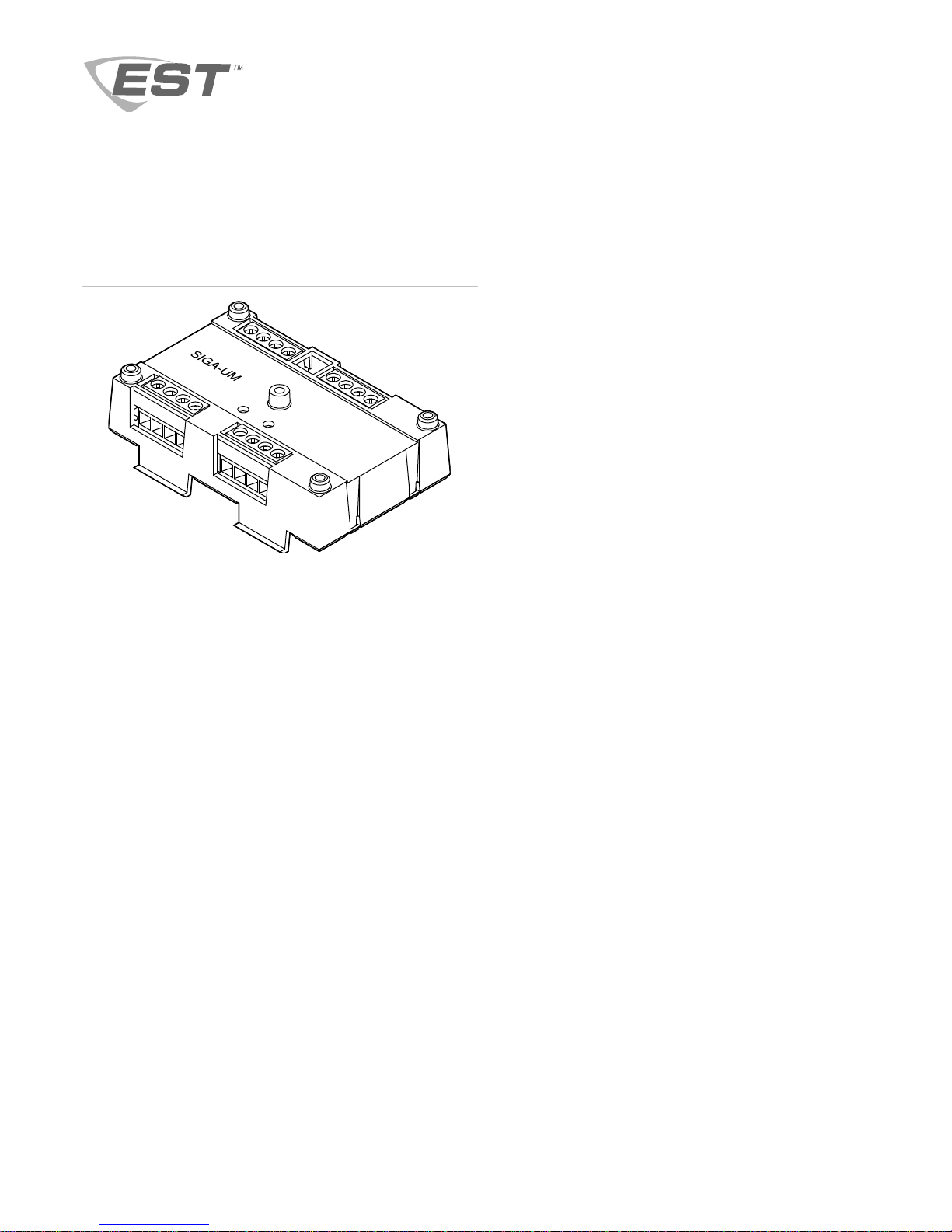
SIGA-UM Universal Class A/B Module
Installation Sheet
Personality codes
Use the personality codes described below to configure the
SIGA-UM module. See Table 1 on page 2 for listing
information. See Table 2 on page 8 for personality code
electrical characteristics.
Personality code 1: Alarm - NO latching (Class B). Factory
default. Configures input 1 or 2 for Class B, normally open dry
contact initiating devices (e.g., pull stations, heat detectors,
etc.). When the NO input contact of an initiating device is
closed, an alarm signal is sent to the loop controller and the
alarm condition is latched at the module.
Description
The SIGA-UM Universal Class A/B Module is an addressable
module that you can configure to provide one of the following:
• Two Class B dry contact initiating device circuits
• One Class A dry contact initiating device circuit
• One Class A or Class B notification appliance circuit
• One Class A or Class B verified two-wire (conventional)
smoke detector circuit without dry contact initiating devices
on the same circuit
• One Class A or Class B unverified two-wire (conventional)
smoke detector circuit with or without dry contact initiating
devices on the same circuit
• One Form C dry contact relay output
The SIGA-UM requires two device addresses on the signaling
line circuit (SLC). Addresses are assigned electronically. There
are no addressing switches.
Diagnostic LEDs provide visible indication of the status of the
module:
• Normal: Green LED flashes
• Alarm/active: Red LED flashes
Personality code 2: Alarm - NO delayed latching (Class B).
Same as code 1 except that contact closure must be
maintained for approximately 16 seconds before an alarm
signal is sent. This code is only for use with nonretarded
waterflow alarm switches.
Personality code 3: Active - NO nonlatching (Class B).
Contact closure causes an active instead of an alarm status
and does not latch at the module. Code 3 is typically used for
monitoring fans, dampers, and doors.
Personality code 4: Active - NO latching (Class B). Contact
closure causes an active instead of an alarm status, which is
latched at the module. Code 4 is typically used for monitoring
supervisory and tamper switches.
Personality code 8: Signal - dry contact output. Configures
the module as a Form C dry relay contact to control external
appliances (door closers, fans, dampers) or equipment
shutdown. Note: Jumper JP1 must be moved to pins 2 and 3
for dry contact operation.
Personality code 9: Alarm - NO latching (Class A). Configures
the module for connection of Class A, normally open dry
contact initiating devices (e.g., pull stations, heat detectors,
etc.). When the NO input contact of an initiating device is
closed, an alarm signal is sent to the loop controller and the
alarm condition is latched at the module.
Personality Code 10: Alarm - NO delayed latching (Class A).
Same as code 9 except that contact closure must be
maintained for approximately 16 seconds before an alarm
signal is sent. Code 10 is typically used with waterflow alarm
switches.
Personality code 11: Active - NO nonlatching (Class A).
Same as code 9 except that contact closure causes an active
instead of an alarm status, and does not latch at the module.
Personality code 11 is typically used for monitoring fans,
dampers, and doors.
© 2016 Walter Kidde Portable Equipment, Inc. 1 / 8 P/N P-047550-1726-EN • REV 08 • ISS 05AUG16
Page 2

Personality code 12: Active - NO latching (Class A). Same as
code 9 except that contact closure causes an active instead of
an alarm status, which is latched at the module. Code 12 is
typically used for monitoring supervisory and tamper switches.
Personality code 13: Alarm - two-wire smoke unverified
(Class B). Configures the module for monitoring two-wire
conventional smoke detectors (that do not require alarm
verification) and normally open contact initiating devices (e.g.,
pull stations, heat detectors, etc.) on the same circuit.
Personality code 14: Alarm - two-wire smoke verified
(Class B). Configures the module for monitoring two-wire
conventional smoke detectors (that require alarm verification).
Normally open contact initiating devices may not be mixed with
two-wire conventional smoke detectors.
Personality code 15: Signal - supervised output (Class A).
Configures the module for connection of a Class A output
notification appliance circuit (NAC). Code 15 is typically used
to control bells, speakers, etc.
Personality code 16: Signal - supervised output (Class B).
Configures the module for connection of a Class B output
notification appliance circuit (NAC). Code 16 is typically used
to control bells, speakers, etc.
Personality code 18: Alarm - soft short latching, European
Style C (Class B). A contact closure causes an alarm status
and a short condition causes a trouble status. Personality code
18 is typically used when a short condition must be
distinguished from an alarm condition.
Personality code 20: Alarm - two-wire smoke unverified
(Class A). Same as personality code 13, except that wiring is
Class A.
Personality code 21: Alarm - two-wire smoke verified
(Class A). Same as personality code 14, except that wiring is
Class A.
For personality codes 13, 14, 20 and 21
First SIGA-UM on a loop to go into alarm will maintain the 2
wire detector circuit voltage and current so that the 2 wire
detector can maintain its LED. Second SIGA-UM on the same
loop to get an alarm from a 2 wire detector will indicate the
alarm at the control panel but will reduce voltage and current
on its 2 wire circuit causing the detector LED to turn on and off.
Installation
Install this device in accordance with applicable national and
local codes, ordinances, and regulations.
WARNINGS
• Connecting a device that exceeds this module’s pilot duty
contact ratings may cause activation failure. This module
does not support capacitive loads. See “Specifications” on
page 7.
• The personality code for this device is factory set to 0.
This module will not operate until it is assigned a
personality code of 1, 2, 3, 4, 8, 9, 10, 11, 12, 13, 14, 15,
16, 18, 20, or 21.
• Electrocution hazard. Dangerous voltages may be present
at the module terminals even when power is shut off.
Table 1: Personality code listing information
Code Description UL 864 CAN/ULC-S527 EN 54-18
1 Alarm - NO latching (Class B) (default)
2 Alarm - NO delayed latching (Class B)
3 Active - NO nonlatching (Class B)
4 Active - NO latching (Class B)
8 Signal - dry contact output
9 Alarm - NO latching (Class A)
10 Alarm - NO delayed latching (Class A)
11 Active - NO nonlatching (Class A)
12 Active - NO latching (Class A)
13 Alarm - two-wire smoke unverified (Class B)
14 Alarm - two-wire smoke verified (Class B)
15 Signal - supervised output (Class A)
16 Signal - supervised output (Class B)
18 Alarm - soft short latching, European Style C (Class B)
20 Alarm - two-wire smoke unverified (Class A)
21 Alarm - two-wire smoke verified (Class A)
2 / 8 P/N P-047550-1726-EN • REV 08 • ISS 05AUG16
Page 3
)
(1)
(2)
Notes
• The module is shipped from the factory as an assembled
unit; it contains no user-serviceable parts and should not
be disassembled.
• This module does not operate without electrical power. As
fires frequently cause power interruption, discuss further
safeguards with the local fire protection specialist.
• This module does not support conventional four-wire
smoke detectors.
To install the module:
1. Write the address assigned to the module on the label
provided and apply the label to the module. Remove the
serial number label from the module and attach it to the
project documentation.
2. Wire in accordance with “Wiring” below.
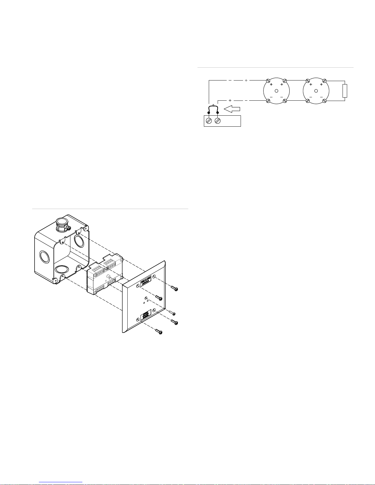
3. Using the self-tapping screw provided, attach the wall
plate to the module. See Figure 1.
4. Using the four machine screws provided, attach the wall
plate and module to the electrical box.
Figure 1: Installing the SIGA-UM module
(1)
To install a transient protector:
1. Install the transient protector across the output circuit
inside the electrical box with the module. See Figure 2.
Figure 2: Bell circuit showing bipolar transient protector
placement
12 11
(1) Normal state (2) Active state
Wiring
Wire this device in accordance with applicable national and
local codes, ordinances, and regulations.
General wiring notes
• Refer to the Signature loop controller installation sheet for
SLC wiring specifications.
• Each terminal on the module is limited to a single
conductor.
(2)
(3)
(5)
(1) Compatible electrical box
(2) SIGA-UM module
(3) Wall plate
(4) #6-32 × 5/8 machine screw
(4X)
(5) #4 × 1/2 self-tapping screw
Protection from transient spikes
For installations in which the output circuit connects to
electromechanical bells or horns, install a bipolar transient
protector (P/N 235196P) to protect the module from transient
spikes caused by switching inductive loads. Locate bells and
horns at least 6 ft. (1.8 m) from the module.
• Only personality codes 13, 14, 20, and 21 support twowire smoke detectors.
• Test resistors are supplied with the SIGA-UM to prevent
trouble signals on unused circuits during installation.
When connecting field wires, remove the test resistors and
install a UL/ULC Listed 47 kΩ EOLR at the end of the
circuit.
(4
Riser wiring notes
• For maximum line impedance, refer to the installation
manual for the fire alarm panel. Maximum circuit
capacitance is 0.1 µF.
• If the riser is used for more than one notification zone,
install in accordance with the survivability from attack by
fire requirements in NFPA 72 National Fire Alarm and
Signaling Code.
Two-wire smoke detector notes
• A maximum of 15 SIGA-UM modules per circuit can be
configured to support two-wire smoke detectors
(personality codes 13, 14, 20, and 21). However, if a
Signature Series IM module or Signature Series detector
with an isolator base is installed on the SLC, only 7
SIGA-UM modules may be configured to support two-wire
smoke detectors.
• Use compatible smoke detectors. See the control panel
compatibility list for type and quantity.
P/N P-047550-1726-EN • REV 08 • ISS 05AUG16 3 / 8
Page 4

)(1)
(2)
• Polarity at terminals is shown in the supervisory condition.
Connect as shown in the diagram. (Polarity reverses on
alarm.)
• IDC wiring is Style B (Class B) or Style D (Class A).
To wire the module:
1. Verify that all field wiring is free of opens, shorts, and
ground faults.
2. Strip 1/4 in. (about 6 mm) from the ends of all wires that
connect to the terminal block of the module.
When stripping wire ends, exposing more wire may cause
a ground fault; exposing less wire may result in a faulty
connection.
3. Make all wiring connections using the appropriate figure
below for the desired function (personality code). See
Figure 3 to Figure 7.
Figure 3: Class B initiating device circuit (personality codes 1, 2, 3, 4, 18)
(2)
(1)
(1) 47 kΩ EOL resistor (PN EOL-47) used for Class B only
(2) For personality code 18, use a 22 kΩ resistor
(3) Input 2: Typical NO initiating device
(4) Input 1: Typical NO initiating device
(5) 10 VDC at 350 µA max.
(6) Signaling line circuit (SLC) to next device
(7) Signaling line circuit (SLC) from previous device, power-limited
and supervised
(1)
(7)
(4)
+
(3)
(1
(5)
321
JP1
+
(6)
4 / 8 P/N P-047550-1726-EN • REV 08 • ISS 05AUG16
Page 5

1
–
–
Figure 4: Form C dry contact relay (personality code 8)
(1)(2)(3)
NO
NC
C
++
(4)
(5)
(6)
321
(7)(8)
JP
(1) SIGA-UM must be installed in the same room as the device it
controls
(2) Power-limited unless connected to a nonpower-limited source. If
the source is nonpower-limited, eliminate the power-limited mark
and maintain a minimum of 0.25 in. (6.4 mm) space from powerlimited wiring. For other mounting methods, see enclosure and
bracket installation sheets to maintain separation of powerlimited and nonpower-limited wiring. The wire size must be
capable of handling fault current from nonpower-limited source.
— or —
Use type FPL, FPLR, FPLP, or permitted substitute cables,
provided these power-limited cable conductors extending
beyond the jacket are separated by a minimum of 0.25 in.
(6.4 mm) space or by a nonconductive sleeve or nonconductive
barrier from all other conductors. Refer to the NFPA 70 National
Electrical Code for more details.
(3) The relay function is programmable
(4) Normally open
(5) Normally closed
(6) Common
(7) Signaling line circuit (SLC) to next device
(8) Signaling line circuit (SLC) from previous device, power-limited
and supervised
Figure 5: Class A initiating device circuit (personality codes 9, 10, 11, 12)
21
3
JP1
(6)
+
+
(5)
(1) Input 1: Typical NO initiating device
(2) 10 VDC at 350 µA max.
(3) Maximum 12.5 Ω resistance per wire for Class A configurations.
(4) Supervised and power-limited unless connected to a nonpower-
limited source. If the source is nonpower-limited, eliminate the
power-limited mark and maintain a minimum of 0.25 in.
(6.4 mm) space from power-limited wiring. For other mounting
methods, see enclosure and bracket installation sheets to
maintain separation of power-limited and nonpower-limited
wiring. The wire size must be capable of handling fault current
from nonpower-limited source.
— or —
Use type FPL, FPLR, FPLP, or permitted substitute cables,
provided these power-limited cable conductors extending
beyond the jacket are separated by a minimum of 0.25 in.
(6.4 mm) space or by a nonconductive sleeve or nonconductive
barrier from all other conductors. Refer to the NFPA 70 National
Electrical Code for more details.
(5) Signaling line circuit (SLC) to next device
(6) Signaling line circuit (SLC) from previous device, power-limited
and supervised
P/N P-047550-1726-EN • REV 08 • ISS 05AUG16 5 / 8
Page 6

l
1
(
)
(
Figure 6: Two-wire smoke detectors and initiating devices (personality codes 13, 14, 20, 21)
(1) Class A two-wire smoke circuit
(2) Maximum 12.5 Ω resistance per wire for Class A configurations
(3) Class B two-wire smoke circuit
(4) Not allowed with personality codes 14 and 21
(5) UL/ULC Listed 15 kΩ EOLR (PN EOL-15) for Class B only
(6) Smoke detector power (24 VDC) from Signature controller,
SMK, or 2-SMK
(7) Signaling line circuit (SLC) to next device
(8) Signaling line circuit (SLC) from previous device, power-limited
(1)(2)
(3)
+
(5)
-
(4)
+
-
(4)
and supervised
(9) UL/ULC Listed 22 kΩ EOLR (PN EOL-22) for Class A only
(9)
(6)
321
JP
(8)
+
+
(7)
Figure 7: Class A or B notification appliance circuit (personality codes 15, 16)
(1) Class A notification appliance circuit
(2) Class B notification appliance circuit
(3) Signal polarity shown when the circuit is normal. Polarity
(2)(3)(4)(5)
-
+
(4) Use twisted pair wires for speaker circuits. All other circuit types
(7)
(9)
+
+
(1)(3)(4)(5)
-
+
-+
321
JP1
+
+
(5) Supervised and power-limited unless connected to a nonpower-
(8)
(6) 47 kΩ EOLR (P/N EOL-47) used for Class B only
(7) Signaling line circuit (SLC) from previous device, power-limited
(10
(8) Signaling line circuit (SLC) to next device
3
)
1
(
2
)
1
(
1
)
1
)
2
1
(9) Audio riser (from previous device)
(10) Audio riser (to next device)
(11) Power-limited regulated, power supply listed for fire protective
(12) Use twisted pair wires for audio riser. All other riser types use
(13) If using horns while connected to a compatible fire alarm control
reverses when the circuit is active
use untwisted pair
limited source. If the source is nonpower-limited, eliminate the
power-limited mark and maintain a minimum of 0.25 in.
(6.4 mm) space from power-limited wiring. For other mounting
methods, see enclosure and bracket installation sheets to
maintain separation of power-limited and nonpower-limited
wiring. The wire size must be capable of handling fault current
from nonpower-limited source.
— or —
Use type FPL, FPLR, FPLP, or permitted substitute cables,
provided these power-limited cable conductors extending
beyond the jacket are separated by a minimum of 0.25 in.
(6.4 mm) space or by a nonconductive sleeve or nonconductive
barrier from all other conductors. Refer to the NFPA 70 Nationa
Electrical Code for more details.
and supervised
signaling use
untwisted pair.
panel that does not produce a temporal pattern, a CDR-3 bell
coder must be used to comply with ANSI S3.41.This module
does not provide signal synchronization.
6 / 8 P/N P-047550-1726-EN • REV 08 • ISS 05AUG16
Page 7

Specifications
Operating voltage range 15.20 to 19.95 VDC
Current See Table 2 on page 8
Output ratings (special
applications)
24 VDC
25 VRMS audio
70 VRMS audio
End-of-Line Resistor
Circuit capacitance
Initiating device circuit (IDC)
Circuit resistance
Circuit capacitance
Alarm current
Operating voltage
Maximum line impedance Refer to the fire alarm panel
Ground fault impedance 10 kΩ
Compatible smoke detectors Refer to the fire alarm panel
Two-wire smoke ripple voltage 2 VAC
EOLR part numbers
15 kΩ
22 kΩ
47 kΩ
Circuit designation
Signaling line circuit
Notification line circuit
Initiating device circuit
Telephone riser circuit
Contact ratings (pilot duty) 24 VDC at 2 A
Contact type Form C, programmable
Compatible electrical boxes 2-1/2 in. (64 mm) deep double-gang
LPCB/CPR electrical box
Requirements
Minimum size W × H × D
Wire size 12 to 18 AWG wire (1.0 to 4.0 mm)
Operating environment
Temperature
Relative humidity
Storage temperature range −4 to 140°F (−20 to 60°C)
2 A
50 W
35 W
47 kΩ, UL/ULC listed
0.1 µF max.
50 Ω max. (25 Ω per wire)
0.1 µF max.
17 mA max.
16.0 to 24.0 VDC
installation manual
compatibility list.
EOL-15
EOL-22
EOL-47
Class A, Style 6 or Class B, Style 4
Class A, Style Z or Class B, Style Y
Class A, Style D
Class B, Style 4
120 VAC at 0.5 A
box;
4 in. square box, 1-1/2 in. (38 mm)
deep, with a double-gang cover
Plastic box with cover plate, no gaps
or unused holes
3.5 × 3.5 × 1.5 in. (85 × 85 × 38 mm)
32 to 120°F (0 to 49°C)
0 to 93%, noncondensing
Regulatory information
FCC compliance This device complies with part 15 of the FCC
North American
standards
EN 54 EN 54-18: 2005 Input/output devices
EU compliance
CPR certificates 0832-CPR-F0335
Rules. Operation is subject to the following two
conditions: (1) This device may not cause
harmful interference, and (2) this device must
accept any interference received, including
interference that may cause undesired operation.
UL864, CAN/ULC-S527
2002/96/EC (WEEE directive): Products marked
with this symbol cannot be disposed of as
unsorted municipal waste in the European Union.
For proper recycling, return this product to your
local supplier upon the purchase of equivalent
new equipment, or dispose of it at designated
collection points. For more information, see:
www.recyclethis.info.
Contact information
For contact information, see www.est-fire.com.
P/N P-047550-1726-EN • REV 08 • ISS 05AUG16 7 / 8
Page 8

Table 2: Personality code characteristics
Personality code Mode of operation Standby current Activated current EOL resistor
1, 2, 3, 4, 18 Class B initiating device circuit 458 µA 700 µA 47 kΩ
8 Form C dry contact relay 127 µA 120 µA N/A
9, 10, 11, 12 Class A initiating device circuit 307 µA 450 µA N/A
13, 14, 20, 21 Two-wire smoke detectors and initiating devices 3.1 mA
(from 3rd wire)
N/A First UM module to go into alarm (Class A or B) N/A 12 mA smoke detector
N/A Each subsequent UM to go into alarm N/A 100 µA (from data line) N/A
15, 16 Class A or B notification appliance circuit 317 µA 140 µA Class A: N/A
N/A Class A: 22 kΩ
Class B: 15 kΩ
N/A
17 mA contact closure
Class B: 47 kΩ
8 / 8 P/N P-047550-1726-EN • REV 08 • ISS 05AUG16
 Loading...