

Page 1

Centurion W and WS Manual
Original Operating Instructions
Rev. 7.6
Page 2
Page 3

Notices
No part of this manual may be reproduced in any form or by any means (including electronic
storage and retrieval or translation into a foreign language) without prior agreement and written
consent of EST Analytical.
Version
Rev. 7.6
Printed in USA
EST Analytical
503 Commercial Dr.
Fairfield OH, 45014 USA
Acknowledgements
Encon® is a registered trademark of EST Analytical
Tekmar® LSC2000 and Tekmar® LSC3000 are registered trademarks of Teledyne
Technologies, Inc.
OI®4460, 4560 and 4660 are registered trademarks of OI Analytical, Inc.
Windows®.Net is a registered trademark of the Microsoft Corp.
Trademark information is accurate to the best of our knowledge at the time of printing.
The symbol marked on the product indicates compliance with the requirements of
CAN/CSAC22.2 No.61010.1, 2nd edition, including Amendment 1.
Page 4

Warranty
The material contained in this document is provided “as is”, and is subject to being changed
without notice, in future editions. EST Analytical warrants the products it manufactures and
distributes, except those specially exempted, to be free from defects for (1) full year from the
date of shipment. This warranty is limited to the original purchaser of the product and is not
transferable. This limited warranty does not extend to any products that have been damaged as a
result of accident, misuse, abuse, or service or modification by anyone.
Except as expressly set forth above, no other warranties are expressed or implied including, but
not limited to, any implied warranties merchantability and fitness for a particular purpose, and
EST expressly disclaims all warranties not stated herein. In the event the product is not free
from defect as warranted above, the purchaser’s sole remedy shall be provided above. Under no
circumstances will EST Analytical be liable to the purchaser or any user for any damages,
including the incidental or consequential damages, expenses, lost profits, lost savings or other
damages arising out of the use or inability to use the product. This warranty shall not be
applicable to the extent that any provision of this warranty is prohibited by any federal, state, or
municipal law that cannot be preempted.
Federal Communications Commissions advisory:
This equipment has not been tested or found to comply with the limits of Class A computing
device, pursuant to part 15 of the FCC Rules. These limits are designed to provide reasonable
protection against harmful interference when the equipment is operated in a commercial
environment. This equipment generates, uses, and can radiate radio frequency energy and, if not
installed and used in accordance with the instruction manual, may cause harmful interference to
radio communications. Operation of this equipment in a residential area is likely to cause
harmful interference in which case the user will be required to correct the interference at his
expense.
CAUTION
A CAUTION notice denotes a hazard. It calls attention to an operating procedure, practice, or
the like that, if not properly performed or adhered to, could result in damage. Do not proceed
beyond a CAUTION notice until the indicated conditions are completely understood and met.
ATTENTION
La mention ATTENTION signale un danger. Il attire l'attention sur une procédure
d'exploitation, la pratique ou la comme ça, s'il n'est pas correctement effectuée ou respectée, peut
entraîner des dommages. Ne pas aller au-delà d'une mention ATTENTION jusqu'à ce que les
conditions indiquées sont complètement comprises et respectées.
Page 5

WARNING
A WARNING notice denotes a hazard. It calls attention to an operating procedure or practice,
or the like that, if not properly performed or adhered to, could result in personal injury of death.
Do not proceed beyond a WARNING notice until the indicated conditions are completely
understood and met.
AVERTISSEMENT
La mention AVERTISSEMENT signale un danger. Il attire l'attention sur une procédure ou une
pratique exploitation, ou le comme ça, s'il n'est pas correctement effectuée ou respectée, peut
entraîner des blessures de la mort. Ne pas aller au-delà d'une mention AVERTISSEMENT
jusqu'à ce que les conditions indiquées sont complètement comprises et respectées.
Page 6

Introduction
…………………………………………………………Chapter 1
1.1 Product Description
1.2 Design Features
1.3 Product Specifications
1.4 Warnings and Symbols
1.5 Disposal and Recycling Information
Centurion W/S Installation and Setup
…………………………………………………………Chapter 2
2.1 General Information
2.2 Work Space Requirements
2.3 Power Requirements
2.4 Unpacking the Centurion
2.5 Centurion Setup/Installation
2.5.1 Connections on the Back of the Centurion
2.5.2 Water Reservoir and Cap Assembly
2.5.3 Feed Gas Installation
2.5.4 Interface Connection
2.5.5 Monitor Setup
2.5.6 Power Connection
2.5.7 Vial Storage Trays
2.5.8 Internal Standard Reservoir Installation
2.5.9 Pressurize System
2.5.10 Instrument Start-up
2.5.11 Water and Soil Axis Calibration
2.5.12 Method Build
2.5.13 System Set-up Complete
Centurion W/S Operation
…………………………………………………………Chapter 3
3.1 Powering on Centurion W/S
3.2 Opening the Centurion W/S Application
3.3 Powering off the Centurion W/S
3.4 Main Screen
3.5 Diagnostics Screen
3.6 Home/Logon Screen
3.7 Exit Icon
Page 7

3.8 Options Screen
3.8.1 Instrument Tab
3.8.2 System Setup
3.8.3 User Accounts
3.9 Sequence Screen
3.9.1 Concentrator #1
3.9.2 Populating the Sequence Table
3.9.3 Run Setup
3.10 Method Screen
3.10.1 General Setup
3.10.2 Internal Standards Tab
3.10.3 Soil Sample Tab (OPTION)
3.11 Run Status Screen
3.12 Run Log Screen
3.13 Help Screen
User Maintenance and Troubleshooting
……………………………………………………………Chapter 4
4.1 Technical Support Contact Information
4.2 Cleaning the Centurion W/S
4.3 Filling the Water Reservoir
4.4 Diagnostics Screen
4.4.1 E-Stop
4.4.2 Flow Pathway Dropdown Menu
4.4.3 Icons
4.4.4 Vial Position
4.4.5 Manual Heater Control
4.4.6 Manual Movement Control
4.5 Manual Functions
4.5.1 Rinse Functions
4.5.2 Drain Sparge Tube
4.5.3 Internal Standards
4.5.4 Sweep Soil Needle
4.5.5 Mechanical Test
4.5.6 Syringe Maintenance
Page 8

4.6 Calibration Functions
4.6.1 Auto Calibration
4.6.2 Manual Calibration
4.6.3 Syringe Calibration
4.6.4 Heater Calibration
4.6.5 Digital Input/Output
4.6.6 Internal Standard Calibration
4.6.7 Stirrer Calibration
4.7 Leak Checking the Soil Pathway
4.8 Replacement of Sampling Station Needle
4.9 Removal/Installation of Water Needle
4.10 Fuse Replacement
4.11 Spare Parts
Flow Diagrams
……………………………………………………………Chapter 5
Appendix A Instructions for the Water and Methanol Extraction
Feature
Appendix B Installation of the Centurion W or WS to an OI 4660
Concentrator
Appendix C Installation of the Centurion W or WS to a Tekmar
Stratum Concentrator
Appendix D Installation of the Centurion W or WS to a Tekmar
3000/3100 Concentrator
Page 9

User Manual
Introduction
Chapter 1
Page 10

1.1 Product Description
The EST Centurion W and WS Purge and Trap Autosamplers are designed to automate
the tedious sample handling procedures associated with purge and trap analysis for
volatile organic compounds (VOC's) under current EPA methods. The EST Centurion
can be used for water and soil (optional) matrices and is designed as a stand-alone unit
for retrofit to any manufactured purge and trap concentrator. Laboratories in today’s
market have enormous challenges to reduce cost and improve productivity. The EST
Centurion provides the flexibility to meet these needs.
The EST Centurion W and WS are a state-of-the art robotic, X-Y-Z axis autosampler
with a unique Windows XPe™ operating platform. The Autosampler has 100 sample
positions, (90 soil), with 2 removable 50 position trays. A vial cooling option is available
which allows the vials to be cooled to below 10°C.
To process a water sample, the 40ml VOA vial is placed in the tray. The Centurion W or
WS robotic arm moves to the programmed vial location and the sample needle is lowered
into the sample vial to a calibrated depth. The sample vial is pressurized, transferring the
sample from the vial through an inert pathway filling a fixed volume sample loop. The
overflow is carried out to waste. The internal standard is injected into the sample stream
and the sample is transferred to the sparge vessel located on the concentrator.
The syringe option for the Centurion W or WS autosampler allows automated sample
dilutions. The dilution range is from 2x to 400x. The Centurion W or WS robotic arm
moves to the vial location as described previously. Next, an aliquot of sample is pulled
from the vial and diluted using the chosen dilution factor, the sample is then sent through
an inert sample pathway, injected with internal standard and transferred to the sparge
vessel on the concentrator. The syringe option also provides the capability to sample
volumes from 5mls to 25mls in 1ml increments.
To process a soil sample, the 40ml VOA vial is placed in the tray. The Centurion WS
robotic arm moves to the programmed vial location. Unlike the water vial which stays in
the sample tray, in the soil mode, the vial is transported to the soil cup. In the soil cup,
internal standard can be transferred into blank water through the fixed volume loop to the
sample. The sample can then be heated, stirred and purged to your specifications.
Finally, the analytes purged out of the sample are transferred to the concentrator through
a heated transfer line.
The Centurion W or WS autosampler will rinse the sample pathway with hot water for
cleaning in preparation of the next sample. The number of rinses and rinse time for the
sample needle and sample loop are programmable. The Centurion W or WS can have two
distinct modes of operation. They are the Single Concentrator and Dual Concentrator
(optional) modes. The single concentrator mode will allow the vial autosampler to run
with one purge and trap concentrator. The optional Dual concentrator mode will allow the
Centurion W or WS autosampler to process and deliver water and soil samples to two
purge and trap concentrators on an efficient alternating basis. The Dual Mode
Page 11

significantly increases the sample throughput of the Autosampler. There is no need to
purchase a second autosampler. All modes perform per their programmed method.
The EST Centurion W or WS is easily programmed through their own keyboard and
mouse. The Centurion W or WS has two USB ports for the keyboard and mouse.
Programming is menu driven and displayed on a color monitor. Parameters can be read
and altered and the screen displays the function in progress during the run.
The Centurion W or WS when connected to an EST Encon Evolution concentrator
further enhances cost savings and improves sample throughput with the Foam Sensor
option on the Evolution. The Centurion W or WS works with the Evolution to rinse the
sparge tube with a pre-programmed number of hot water rinses whenever a foaming
sample is detected. This option prevents the accidental transfer of a foamed sample to the
GC column which can result in down time and costly repairs.
NOTE: For clarification purposes, the use of the word Centurion throughout the
manual shall refer to both the Centurion W and WS.
1.2 Design Features
Dual 50 position removable sample trays for 40ml VOA vials.
Rugged X-Y-Z platform.
Windows XPe™ operating platform.
Runs blanks from its own blank/wash water reservoir.
Sample Loop sizes range from 5, 10, 15, 20 or 25ml.
Syringe Option, allows dilutions from 2x to 400x and sample sizes from 5mls to 25mls
in 1ml increments.
All sample pathways are chemically inert, manufactured from PEEK®, Stainless Steel,
or Teflon.
Separate needles for the soil and water modes thus minimizing carryover between the
two matrices.
Built in Minimizer Valve aiding in the removal of contamination on the soil side by
diverting some of the bake flow from the concentrator through the soil pathway of the
Centurion.
Programmable volume addition of Internal Standards/Surrogates.
Optional sample tray cooling capability. Optional refrigerated chiller is required.
Priority Sample feature allows the current analysis to be interrupted for RUSH
samples.
Fast easy programming from the keyboard/mouse combination.
Programmable methods may be stored for various method configurations.
A sample may be run from any position in the tray.
Page 12
Easy hook up and installation to all manufactured purge and trap systems.
Hot water rinse utilizes a cartridge heater to heat blank water to 90C prior to flushing
sample pathways and the purge vessel.
Optional Dual concentrator mode for both water and soil matrices.
Optional Dual GC mode.
1.3 Product Specifications
Tray Capacity:
100 sample vials. 40 ml EPA VOC
Sample Volume:
Indoor Use
Altitude:
Operating
Temperature:
Relative Humidity:
Voltage:
Current:
Battery:
Installation Category:
Pollution Degree:
5, 10, 15, 20, 25ml sample loop, 5 to 25ml volume
syringe (1ml increments for syringe)
Up to 2000 m
15C to 25C; Storage Temperature 5C to 85C
10 to 90%
115/230VAC ( 10%), 50/60Hz
Model
CenturionW 4.0 2.0
CenturionWS 8.0 5.0
115VAC 230VAC
Current(A) Current(A)
CR2032 battery contained on SBC (CPU) board
II
2
Weight:
Size:
Gas Requirements:
Approximately 80 lbs; 36.5 Kilograms
24.5”W (62.2 cm) x 27”D (68.6 cm) x 25” H (63.5 cm)
Helium or Nitrogen 60-80 PSI (414-552kPa) 99.999%
GC/MS grade purity; BTU/hr. = NA (compressed gas
used for pressurization only)
Page 13

1.4 Warnings and Symbols
English
Warnings in the manual or on the Centurion to be observed during installation, operation,
service and/or repair of the instrument. EST Analytical will assume no responsibility for
customers failing to comply with the safety precautions stated.
Use of the Centurion for something other than the intended use of the instrument is
prohibited.
The use of the Centurion is for trained personnel only.
Personnel operating the Centurion should wear safety glasses and gloves where
appropriate.
The Centurion is not intended for use in a hazardous environment.
Installation of the Centurion requires that there is nothing blocking the vents of the
system.
Installation of the Centurion requires that the instrument be placed on a non-flammable
surface capable of handling the weight of the instrument.
Heaters and heated transfer line(s) require surrounding space to be non-combustible
material.
Sound pressure level of the Centurion is 65db (A).
When cleaning the Centurion please refer to section 4.2 of the User Manual. No other
cleaning agents may be used other than what is specified in this section.
Français
Les avertissements dans le manuel ou sur le Centurion à respecter lors de l'installation , le
fonctionnement , le service et / ou la réparation de l'instrument . EST analytique n'assume
aucune responsabilité pour les clients qui ne respectent pas les consignes de sécurité
indiquées .
Utilisation du Centurion pour autre chose que l'utilisation prévue de l'instrument est
interdite.
L'utilisation du Centurion est de personnel qualifié seulement .
Le personnel d'exploitation du Centurion doivent porter des lunettes de sécurité et des
gants le cas échéant .
Le Centurion n'est pas destiné à être utilisé dans un environnement dangereux .
L'installation du Centurion exige que rien ne bloque les évents du système .
Montage du Centurion nécessite que l'instrument est placé sur une surface non
inflammable capable de supporter le poids de l'instrument.
Chauffe et ligne de transfert chauffée (s) nécessitent de l'espace environnant à un
matériau incombustible .
le niveau de la Centurion de pression sonore est de 65db ( A) .
Lors du nettoyage du Centurion s'il vous plaît se référer à la section 4.2 du Manuel de
l'utilisateur . Pas d'autres agents de nettoyage peuvent être utilisées autrement que ce qui
est spécifié dans cette section.
Page 14
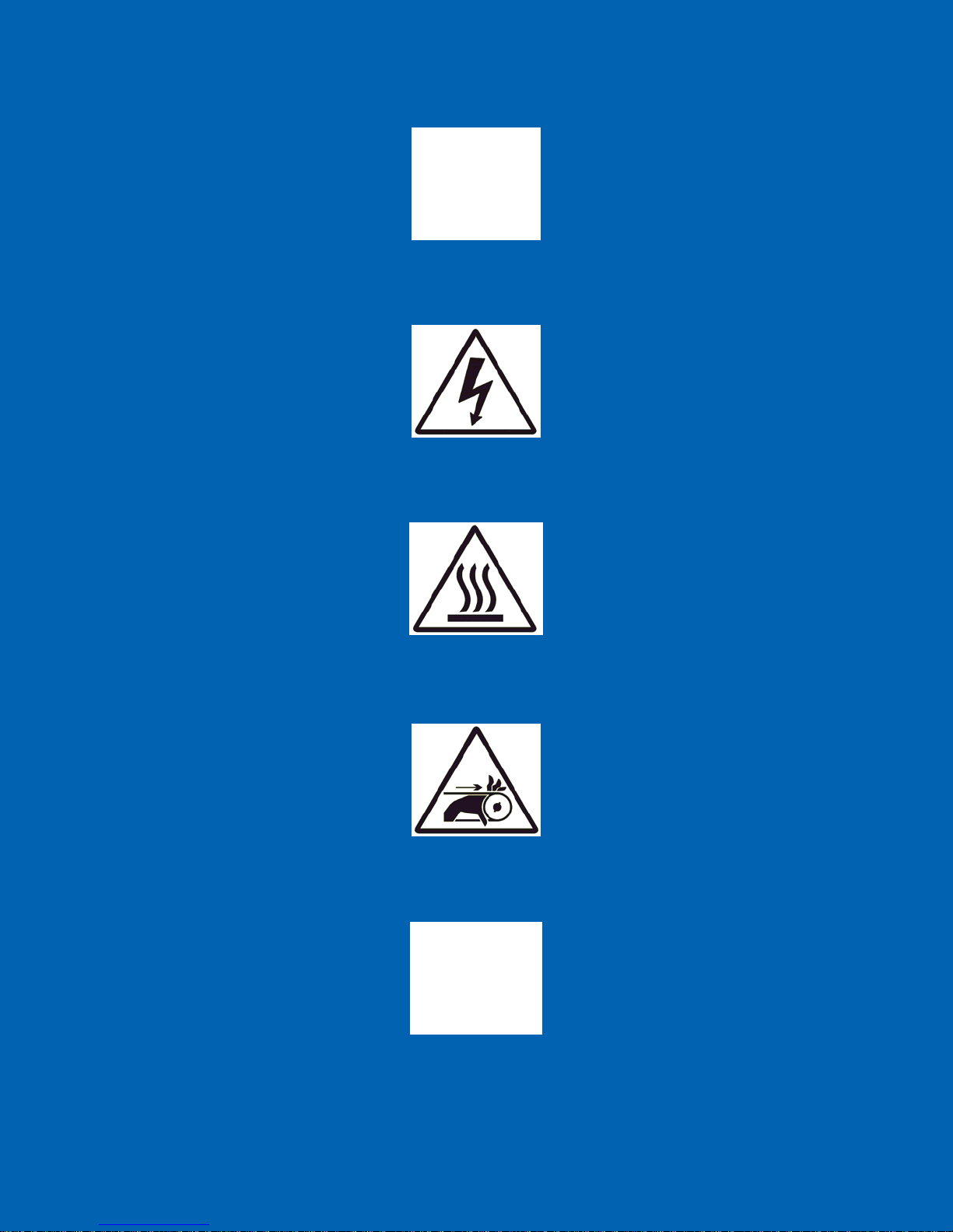
See Accompanying Instructions for more Information
Voir les instructions d'accompagnement pour plus d'informations
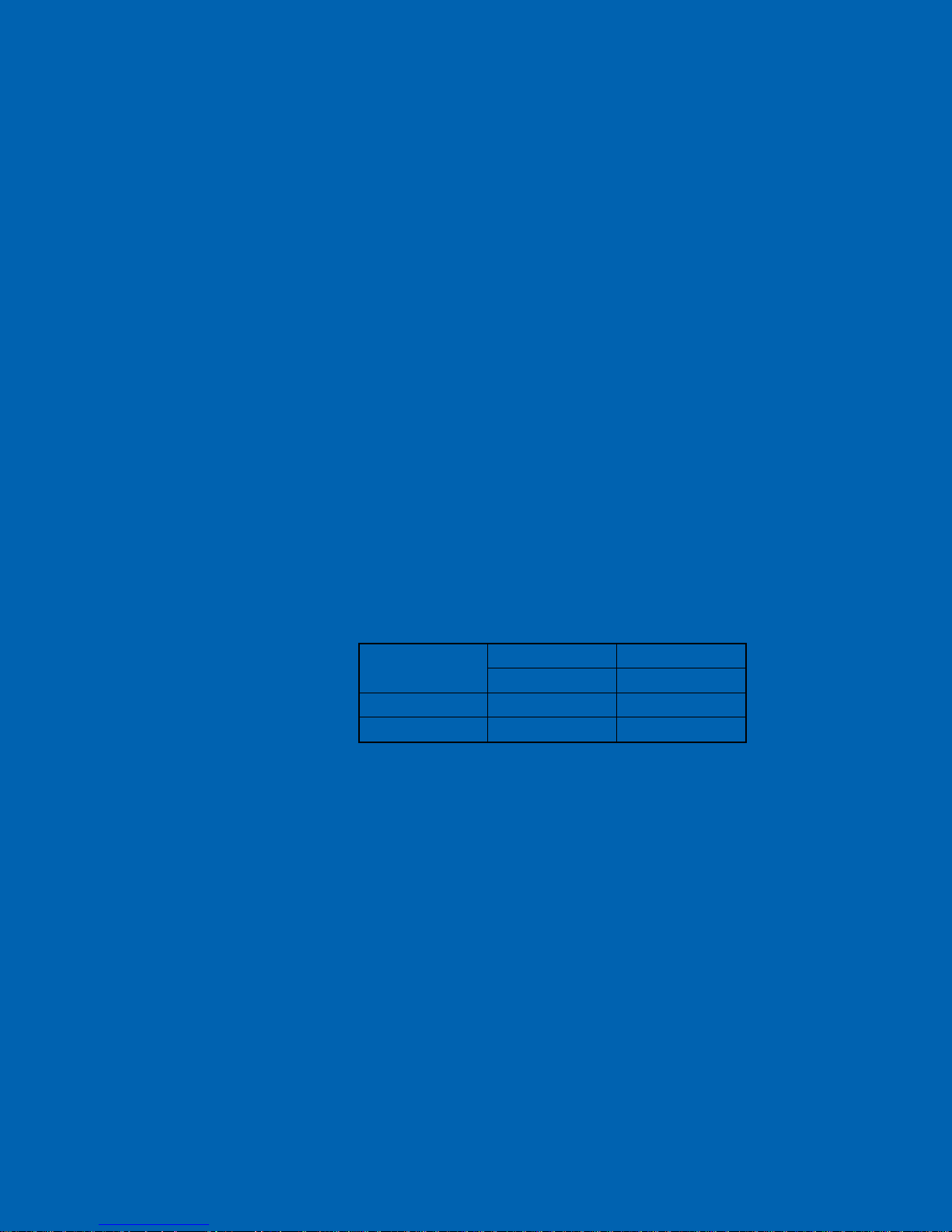
Indicates an Electrical Hazard
Indique un danger électrique
Indicates Hot Surface
Indique surface chaude
Indicates a Risk of Hand Entanglement
Indique un risque d'étranglement pour les mains
Indicates a Sharp Point
Indique une pointe acérée
Page 15

Indicates Bulky/Heavy Item, Use Two Person Lift
Indique objet volumineux / lourds, utilisez deux personnes ascenseur
1.5 Disposal and Recycling Information
United States:
This symbol indicates that your product must be disposed of properly according
to local laws and regulations. When your product reaches its end of life, contact
your local authorities to learn about recycling options.
European Union:
This symbol above means that according to local laws and regulations your product should be
disposed of separately from household waste. When this product reaches its end of life, take it to
a collection point designated by local authorities. Some collection points accept products for
free. The separate collection and recycling of your product at the time of disposal will help
conserve natural resources and ensure that it is recycled in a manner that protects human health
and the environment.
Page 16

User Manual
Installation and Setup
Chapter 2
Page 17

2.1 General Information
The system setup and installation section is intended to be as thorough as possible. If indoubt at any point, please contact EST Analytical toll free at (800) 283-3510. If
installation is not directed or performed by EST Analytical personnel, the operator must
be thoroughly familiar with setup and installation sections of this manual.
NOTE: Failure to follow the installation instructions as set forth could result in
damage to the product and nullify the warranty.
2.2 Work Space Requirements
The Centurion foot print is 24.5”W (62.2 cm) x 27”D (68.6 cm) x 25” H (63.5 cm).
NOTE: Allow for added space on all sides of the instrument for proper ventilation.
2.3 Power Requirements
Voltage:
115/230 VAC (+/- 10%)
50/60 Hz
8.0/5.0 Amps
15/20A circuit breaker
2.4 Unpacking the Centurion
Figure 2a: Shipping Container
The Centurion is packaged in one Carton containing all components necessary for
instrument installation and operation.
NOTE: Retain all shipping material.
Page 18

Before un-strapping the Centurion Box, visually inspect the shipping carton for any
damage. Call EST Analytical at (800)283-3510 immediately if visual damage is present.
Cut the strapping and lift the top box cover off the box and put aside. Lift the outer box
shell off the Centurion and put aside. Remove the excess foam packing material from the
top of the Centurion and put aside.
Figure 2b: Instrumentation Packing 1
Remove the two boxes inside of the Centurion main body. Box #1 contains the vial
storage trays. Box #2 will contain the installation kit, I/O cable, keyboard, mouse,
internal standard vessel, and power cord.
Figure 2c: Instrumentation Packing 2
Page 19

With the help of another person tilt the Centurion on one side and remove the
foam inserts. The Centurion in now ready to place on the bench. With one person on
EACH side of the Centurion transfer the Centurion to the bench.
NOTE: The Centurion needs to be lifted from the base of the instrument.
WARNING: The Centurion needs enough space on all sides of the instrument to
ensure proper cooling of instrument components AND to ensure that the power cord
can be easily disconnected.
AVERTISSEMENT: Le Centurion besoin de suffisamment d'espace sur tous les
côtés de l'appareil pour assurer le bon refroidissement des composants de
l'instrument et de veiller à ce que le cordon d'alimentation peut être facilement
déconnecté.
2.5 Centurion Setup/Installation
2.5.1 Install all connections at the rear of the instrument:
Keyboard-grey USB cable, see Figure 2d.
Mouse-white USB cable, see Figure 2d.
Figure 2d: Centurion Keyboard, Mouse and Interface Connections
Waste (W)-Black Tubing, see Figure 2e.
o Flangeless Nut-Green
o Flangeless Ferrule-PEEK
Page 20

Figure 2e: Waste Line
Concentrator (1)-PEEK Tubing, see Figure 2e and 2f
o Super Flangeless Nut-black
o Super Flangeless Ferrule-ring/PEEK ferrule
o Connect to Concentrator (1) three way valve-green nut and
natural ferrule.
Figure 2f: Water Transfer Line Connection to Concentrator
Concentrator (2)-if applicable, same connections as Concentrator (1).
Concentrator (1)-Soil Purge Gas Line Connections – If Applicable.
(Note: Shipped as an assembly.)
o Connect PEEK tubing (red) to Concentrator (1) purge bulkhead
with Upchurch nut and Ferrule. See Figure 2g.
Page 21

Figure 2g: PEEK Lines from Centurion to Encon Evolution
o Connect other end of the PEEK tubing (red) to the Centurion WS
port labeled Concentrator (1) Purge Bulkhead using Reverse Nut
PEEK and ferrule. See Figure 2h.
Figure 2h: PEEK lines on the back of the Centurion
Page 22

o Connect PEEK tubing (blue) to Concentrator (1) glassware on the
purge side using the 1/16-1/4 Union. See Figure 2g.
o Connect the other end of the PEEK tubing (blue) to the Centurion
WS port labeled Concentrator (1) Sparge Tube using Reverse Nut
PEEK and ferrule. See Figure 2h.
Concentrator (2)-if applicable, same connections as Concentrator (1).
Soil Transfer Line
o Connect Valco nut on the end of the heated transfer line to the four
way Tee in the concentrator. See Figure 2i.
WARNING: The heated transfer line needs to be routed at least
10 inches away from any adjacent objects. All other cables need to
be routed away from the transfer line heaters also.
AVERTISSEMENT: La ligne de transfert chauffée doit être
acheminé au moins 25.4 centimètres de tous les objets adjacents.
Tous les autres câbles doivent être acheminés à l'écart des
réchauffeurs de conduites de transfert aussi.
Pressure Line (Water Bottle)-Black tubing.
o Quick connect fitting to back panel. See Figure 2j
Figure 2j: Water Bottle Pressure Line, Cold and Hot Water Lines
Figure 2i: Soil Transfer Line
Page 23

Cold Water Input (C)-Teflon Tubing, See Figure 2j
o Flangeless Nut-Green
o Flangeless Ferrule-PEEK
Hot Water Input (W)-Teflon Tubing, See Figure 2j
o Flangeless Nut-Green
o Flangeless Ferrule-PEEK
2.5.2 Water Reservoir Cap Assembly
Install Nut and Ferrule on the reservoir end of the cold and hot water
pickup lines. See Figure 2k.
o Flangeless Nut-Green
o Flangeless Ferrule-PEEK
Install cold and hot water pickup lines through two of the three holes in
the water reservoir plug. Lines need to reach the bottom of the reservoir.
Install the frits to the ends of the cold and hot water pickup lines after
they have been installed through the reservoir plug. See Figure 2l.
o Frit
Figure 2k: Reservoir Lines
Page 24

Figure 2l: Water Line Frits
Fill reservoir with organic free water.
Install o-ring onto the smaller flange end of the reservoir plug
Install the black pressure line into the cap allowing the end of the line to
come through the hole and into the reservoir about 3-5mm deep or cut
flush with the bottom of the cap insert.
Screw the cap onto the reservoir. See Figure 2m.
Figure 2m: Reservoir Bottle
Page 25

2.5.3 Feed Gas Installation
Install a Tee to the end of the feed gas line and Tee in the feed gas to the
Centurion W/S with the other end of the Tee going to the concentrator.
NOTE: Make sure the pressure is between 60-80psi (414-552kPa).
2.5.4 Interface Connection
Install supplied interface cable between Centurion and Concentrator. In
Single Concentrator Mode the Centurion is equipped with a 25 pin
connector which connects to Concentrator (#1). If the Centurion is
equipped with the optional Dual Mode the interface cable will have a
second 25 pin male connector that will connect to Concentrator (#2) in
the same manner as Concentrator #1. The Centurion can be interfaced
with different manufactured concentrators and or multiple GC’s. These
configurations require a custom cable. See Appendix A for the specific
instructions on installation to other concentrators. Call EST at
(800)283-3510 if you have any question about your interface connections.
See Figure 2d.
2.5.5 Monitor Setup
Mount the monitor to the mounting bracket with the four screws given in
the Monitor box. Plug the VGA cable to the VGA port on the back of the
monitor. Plug power cable to the 24Vdc power port on the back of the
monitor as shown below in Figure 2n.
Figure 2n: Monitor Connections
Page 26

2.5.6 Power Connection
Plug the power cord into the Power Entry module on the back of the
Centurion. See Figure 2o.
WARNING: Ensure proper grounding of the Centurion system
before powering the system up.
AVERTISSEMENT: S'assurer de la bonne mise à la terre du système
Centurion avant de mettre le système en place.
Figure 2o: Power Entry Module and Helium Input Connector
2.5.7 Vial Storage Trays
Place the vial storage trays onto the base of the Centurion. The trays have
a key on the bottom side which will fit the slots on the base of the
Centurion. See Figure 2p.
Figure 2p: Vial Storage Tray
Page 27

2.5.8 Internal Standard Reservoir Installation
Rinse and fill IS reservoir(s) with methanol.
Place the knurled nut(s) and teflon ferrules on the reservoir(s) and tighten
the IS reservoir(s) in the respective position(s). NOTE: Tighten until
finger tight and use the provided IS mount wrench to tighten the IS
vessel about ¼ of a turn more. See Figure 2q. NOTE: The system
must be de-pressurized in order to remove the IS reservoir.
2.5.9 Pressurize System
Turn on the pressurization valve on the back panel of the Centurion WS.
See Figure 2r.
Adjust the system pressure on the front panel to 14-15psi (97-103kPa). If
the pressure is set too high it may be necessary to back of the regulator
and release the pressure by turning off the pressurization valve. In order
for the gauge to drop in pressure, an IS mount may need to be loosened.
Allow the pressure to bleed off of the system, the re-pressurize the system
and adjust the front panel system pressure to the required set-point.
Figure 2q: Internal Standard Vessels
2.5.10 Instrument Start-up
Turn on the instrument.
Login-Password for the Administrator is ESTAnalytical (Case Sensitive).
Wait for the IO system configuration to load; then open the Application.
Figure 2r: System Pressure Switch
Page 28
Proceed to the Diagnostics screen and prime the IS vessel(s) three times
with methanol. NOTE: Refer to section 4.5.3 of the Diagnostics
Chapter on how to prime the IS vessel(s).
De-pressurize the system, remove the IS vessel(s) and rinse and re-fill
them with your required IS and place them back on the system.
Re-pressurized and prime a second time with the IS.
2.5.11 Water and Soil Axis Calibration
Perform a Mechanical Test; refer to section 4.5.5 in the User
Maintenance and Troubleshooting Chapter.
If the system fails the Mechanical Test, the water and soil axis will need
to be calibrated. Refer to section 4.6.1 for instructions on how to auto
calibrate the Centurion.
2.5.12 Method Build
Setup a user method by setting all times. NOTE: Make sure that
the set desorb time on the Centurion WS method is the SAME as the
desorb time of the concentrator.
Use the water waste line to monitor if the sample fill time has been set
correctly.
Verify the water sample delivery time by evidence of gas flow into the
sparge tube after complete water delivery.
Refer to Table 2a for typical Method settings for the WS with a 5ml loop.
Purge and Trap Auto-Sampler EST Centurion WS
Sample Type Water
Sample Loop Fill Time (sec) 12
Loop Equilibration Time (sec) 5
Sample Transfer Time (sec) 15
Needle Rinse Time (sec) On/10
Needle Sweep Time (sec) 5
Sample Loop Rinse Time (sec) On/10
Sample Loop Sweep Time (sec) 5
Concentrator Desorb Time (sec) 60
Sparge Rinse Time (sec) On/25
Sparge Rinse Transfer Time (sec) 20
Concentrator #1 Cycle Time (min) 0
Number of Rinse Cycles 2
Number of Foam Cycles 1
Water Heater Temp. (°C) 85
Table 2a: Typical Centurion Water Parameters for a 5ml Loop
2.5.13 System Set-up is Complete
You are now ready to run.
Page 29

User Manual
Operation
Chapter 3
Page 30

3.1 Power On
1. Please read the entire manual and become familiar with the operation of the
Centurion prior to installation of the autosampler. NOTE: Only a trained operator
may run the Centurion.
2. Be sure that all electrical connections are in place and the plumbing connection s, both
water and gas, are free of leaks.
3. Check all waste lines and ensure that they are properly routed and contained before
powering on the autosampler.
4. Press ON at the power switch located on the right side of the rear panel.
5. The embedded Windows XPe
™ operating system will load and the IO System
Configuration will load. The IO System Configuration is a self-loading
communication device between the Centurion and the Windows XPe™ operating
system.
3.2 Open the Centurion Application
1. The user will control the operation of the Centurion with a mouse and keyboard.
2. <click> the Centurion icon on the desktop.
3. The EST Analytical screen will appear while the application is loading.
4. After the application has loaded the user will be prompted to log on with a password
as shown in Figure 3a. NOTE: The password for the Centurion is ESTAnalytical
(case sensitive).
5. The user will then be prompted to Home All Axes as shown in Figure 3b. The
Centurion must be homed prior to operation.
Figure 3a: Log in Screen
Figure 3b: Home Axes Screen
Page 31

6. If the Centurion is a WS, the user will then be prompted: Is Gripper Clear from
Soil Cup? As shown if Figure 3c. <click> Yes if the gripper is clear from the soil
cup and the main screen will then be displayed. If the gripper is not clear <click> No
and the user will be prompted to Please clear Gripper from Soil Cup as shown in
Figure 3d. Next the user will see the Gripper Axis Movement screen and the F/R
Axis Movement screen as shown in Figure 3e and 3f respectively. Here you will use
the software to move the gripper clear of the soil cup. Use Gripper Axis Movement
to clear the gripper vertically and F/R Axis Movement to clear the gripper in the
Front/Rear directions. Finally, with the gripper clear of the soil cup, the user will be
able to home all axes.
Figure 3c: Is Gripper clear from Soil Cup Popup
Figure 3d: Please clear Gripper from Soil Cup Popup
Figure 3e: Gripper Axis Movement Screen
Page 32

Figure 3f: F/R Axis Movement Screen
Gripper Movement and F/R Axis Movement: The Position count displayed is the
current position of the gripper. To move the gripper, enter the desired Increments
and select Jog + or Jog -. <click> Referenced to home the axis.
7. The Main screen will then be displayed as shown in Figure 3g. The Centurion is now
ready for operation.
Figure 3g: Centurion Main Screen
Page 33

3.3 Power Off
1. From the Main screen <click> Exit, this will close the Centurion application.
2. <click> Start from the taskbar.
3. Select Shut Down.
4. After Windows XPe™ has shut down it will prompt the user: It is now safe to turn
off your computer.
5. Press OFF at the power switch located on the right side of the rear panel.
NOTE: Using other means to power off the Centurion may result in damage to
the operating system.
3.4 Main Screen
The Centurion Main screen, shown previously in Figure 3g, displays a series of icons
which allow the user to navigate through the application in order to build methods, run
diagnostics, view run logs and monitor the status of the autosampler. Upon opening a
screen, all icons will be displayed along the left side to allow the user to simply click on
an icon to load another screen.
3.5 Diagnostics Screen
Refer to Maintenance and Troubleshooting for the Diagnostics Screen functions in
Chapter 4.
3.6 Home/Log On
This icon serves a dual purpose. On the Main screen it serves as the user Log On icon
and the Home All Axes popup. To return to the Main screen from any other accessed
screen, <click> the Home icon and the Main screen will be displayed.
3.7 Exit
The Exit icon is only displayed on the Main screen. The user cannot exit the application
without first returning to the Main screen with the Home icon. To exit the Centurion
application, <click> the Exit icon. This will drop the application and return to the
Windows XPe
™ desktop.
Page 34

3.8 Options
The Options screen enables the instrument options. To open, <click> the Options icon
and the screen will be displayed as shown in Figure 3h. This screen contains three tabs:
Instrument, System Setup and User Accounts.
Figure 3h: Options Screen Instrument Tab
3.8.1 Instrument: <click> the Instrument tab and the screen will appear as shown in Figure
3h. This provides information specific to the Centurion.
Instrument Information – Listed in the instrument information box is the
instrument name, serial number and software version. This information is used
when contacting EST Technical Support and generating key codes for options to
the Centurion.
Instrument Options – Listed in the instrument options box are the manufacturer
supplied key codes to activate hardware options.
3.8.2 System Setup: <click> the System Setup tab, the screen will appear as shown in Figure
3i. From this screen select the instrument configurations.
Page 35

Figure 3i: Options Screen System Setup Tab
Operation Selection: There are two options available: Remote or Local mode.
Remote – When remote mode is selected the Centurion will only start the
sample process when a purge ready signal is received from the
concentrator. If the Centurion is ready to start the sample process and the
concentrator is not in purge ready, a Waiting for Purge Ready message
will be displayed on the Run Status screen.
Local – When the local mode is selected the Centurion will not wait for a
purge ready signal from the concentrator before beginning the sample
process.
Chiller Temperature Alarm (option): To activate the alarm <click> Enable
Alarm. Select Stop Sequence and the sequence will stop if the alarm is
triggered. Select Continue Sequence and the sequence will continue even though
the alarm is triggered.
Save – To save the instrument configuration, <click> the Save button.
3.8.3 User Accounts - <click> the User Accounts tab, the screen will appear as shown in
Figure 3j. This tab provides the current user logon information including date, time and
duration.
Page 36

Figure 3j: Options Screen User Accounts Tab
Add: This selection allows for the addition of Centurion users.
Remove: This selection allows for the removal of Centurion users.
Properties: This selection allows for the level of access to a specific user. The
user(s) will be identified and set up by an authorized Field Service Engineer
during installation.
3.9 Sequence Screen
The Sequence Screen provides the ability to create a sequence of water and/or soil
samples using the Centurion methods. <click> the Sequence icon and the screen will
appear as shown in Figure 3k. This screen will contain two or three tabs: Concentrator
#1 and Run Setup. (Concentrator #2 if the unit has the Dual Mode option.) The
following steps for Concentrator #1 also apply to Concentrator #2.
NOTE: The water sample sequence range is from tray position 1 through 100. The
soil sample sequence range is from tray position 1 through 90.
Page 37

Figure 3k: Sequence Screen Concentrator Tab
3.9.1 Concentrator #1 (Concentrator #2) : <click> on the Concentrator #1 tab and the
screen will appear as shown in Figure 3k.
Line: This is the sequence line number.
NOTE: The sequence always starts at line 1.
Description: Description may be added by the user for information purposes
only.
Vial: This is the sample tray position.
Method: This is the method to be used for the sample line.
Blank: The number of Centurion water system blanks run prior to the sample in
line.
Runs: The number of runs per vial. Water samples only.
Dilute: The dilution ratio of the sample.
Extract: N/A Option to be released at a later date.
IS: Indicates if the internal standard additions are manually selected from the
Runs Per Vial option. Refer to Runs Per Vial section of 3.9.2 for additional
information.
Page 38

PR: Denotes that a priority sample has been added to a sequence in progress.
3.9.2 Populating the Sequence Table
Start Vial: <click> Start Vial to enter the first tray position of a sample
sequence.
# of Vials: Enter the number of vials in the sample sequence.
# of Blanks: Enter the number of Centurion system blanks to be run prior to each
sample.
Runs Per Vial: Enter the number of runs per vial. The water sample needle will
remain in the sample vial for all subsequent runs. To override the internal
standard addition from the method <click> the Runs Per Vial tab and the screen
will appear as shown in Figure 3l. It is then possible to select which internal
standard and the amount of the internal standard that will be added to which run
per vial.
NOTE: If the Runs Per Vial option is selected, then all internal standard
additions must be selected from this location as using this option overwrites
the internal standard addition of the chosen method.
NOTE: This feature is for water analysis only.
Figure 3l: Runs Per Vial Tab
Select Method: To specify the method for the sequence line, <click> the Select
Method drop down to display all available methods. The chosen method will be
displayed as shown in Figure 3m.
Figure 3m: Select Method Tab
Insert: To populate the sequence field <click> the Insert button, shown in
Figure 3n.
Figure 3n: Insert Tab
Page 39

Priority: If the sequence is active and a sample(s) needs to be run as a priority,
first establish the start vial and number of vials to be run as priority. Next,
<click> the Priority button, shown in Figure 3o, the priority run(s) will be
inserted into the sequence ahead of the next run in the sequence.
Figure 3o: Priority Tab
Delete: To delete sequence lines, enter the start vial and number of vials and
<click> the Delete button shown in Figure 3p.
Figure 3p: Delete Tab
Vial Overlap (Dual Mode only): The Centurion is capable of running the same
sample vial from the same sample tray position on two concentrators. When
populating a sequence on concentrator 2, if the tray positions overlap, a popup
will appear as shown in Figure 3q. Select OK to continue or Cancel to stop.
Enter Description: To add a description to the sample in the sequence <click>
the Enter Description button. See Figure 3r.
Figure 3q: Position Overlap Popup
Figure 3r: Enter Description Tab
Page 40

Dilution (Syringe Mode only): The Centurion is capable of performing
dilutions. To do a dilution <click> on the sample that needs dilution and <click>
on the arrow next to the dilution tab and a drop down menu will display several
dilution factors. See Figure 3s. Choose the dilution factor that is needed and the
Centurion will perform the dilution automatically within the sample sequence.
Figure 3s: Dilution Screen for Syringe option
Page 41

3.9.3 Run Setup: <click> on the Run Setup tab and the screen will appear as shown in Figure
3t.
Figure 3t: Run Setup Tab
Concentrator Start Selection: In dual concentrator mode select Concentrator
#1 or Concentrator #2 to begin the sequence.
Error Setup
Stop On No Vial: Select Stop On No Vial and the Centurion will stop if no
sample vial is detected in the sample tray. The autosampler will make three
attempts to sense a vial before stopping. If Stop On No Vial is not selected and a
vial is not sensed in the tray position the Centurion will run a false sample to keep
the GC sequence on track and will then continue to the next vial in the Centurion
sequence.
Automatic Correction (Dual Mode): Select Automatic Correction. In dual
concentrator mode if the Centurion does not receive a purge ready signal from
one of the concentrators the autosampler will continue to run the remaining
sequence of the active concentrator. If Automatic Correction is not selected, the
Centurion will not accept the next purge ready signal from the active concentrator
and the sequence will not continue.
Page 42

Correct Entire Sample Table (Dual Mode): Select Correct Entire Sample
Table. In dual concentrator mode if the Centurion does not receive a purge ready
signal from one of the concentrators, the autosampler will adjust the sequence to
run the remaining sequences for both concentrators on the active concentrator.
NOTE: All corrected samples will be analyzed using the active
concentrator’s method.
Disable Soil Vial Check: Select Disable Soil Vial Check and the Centurion will
not check for the presence of a soil vial in the soil cup before and after delivery of
a new soil sample vial.
NOTE: Disabling soil vial check may result in potential damage to the
autosampler and/or sequence failure.
Disable Syringe Position Check: Select Disable Syringe Position Check and
the Centurion will not check the position of the syringe in the syringe driver after
the sample is dispensed.
Concentrator Recycle Selection: Select Concentrator #1 and/or Concentrator
#2. When selected, the sample sequence table will be repeated after the
conclusion of the last sample in the sequence and continue for as many cycles as
entered. In this mode one re-recycle equals the original sequence run.
GC Selection: Select Dual GC if two GCs are inline.
Printing a Sequence: <click> Printer and the sequence will print.
NOTE: To print, a printer must be interfaced with the Centurion.
Saving a Sequence: <click> Save and the sequence will be saved.
Open a Saved Sequence:
sequences are available to be loaded.
3.10 Method Screen
The Method screen contains the settings and conditions necessary to create a water or soil
method. <click> the Method screen icon, the Method screen will be displayed as shown
in Figure 3u (Loop General Setup Screen) and 3v (Syringe General Setup Screen).
The Method screen will consist of three tabs: General Setup, Internal Standards and
Soil Sample (if the Centurion is a WS). NOTE: For a Centurion WS with a syringe
option, the user has the option to run Sample Prep mode Methanol Extract mode.
Please refer to Appendix A for these descriptions.
<click> Open and all previously saved
Page 43

Figure 3u: Loop General Setup Screen
Figure 3v: Syringe General Setup Screen
Page 44

3.10.1 General Setup: <click> on the General Setup tab and the screen will appear as
shown in Figures 3u and 3v.
Loop General Setup (Figure 3u):
Sample Type: Select from Blank, Soil or Water by <clicking> through the field.
CAUTION: Soil vials may be hot. Use protective gloves when removing
soil vials from the sampling station.
ATTENTION: les flacons de sol peuvent être chauds. Utilisez des gants
de protection lors de l'enlèvement des flacons de sol provenant de la station
d'échantillonnage.
Sample Fill Mode: Loop
Sample Loop Fill Time (sec): Enter the time to fill the sample loop.
Loop Equilibration Time (sec): Enter the time to equilibrate the sample loop
after filling.
Sample Transfer Time (sec): Enter the transfer time to fill the concentrator
sparge tube.
Needle Rinse Time (sec): Enter the time to rinse the sample needle after
delivering the sample to the sparge tube.
Needle Sweep Time (sec): Enter the time to sweep the sample needle after rinse.
Sample Loop Rinse Time (sec): Enter the time to rinse the sample loop after
delivering the sample to the sparge tube.
Sample Loop Sweep time (sec): Enter the time to sweep the sample loop with
helium after the rinse.
Concentrator Desorb Time (sec): Enter the concentrator desorb time. NOTE:
This time must equal the concentrator desorb time.
Number of Sparge Rinse Cycles: Select loop, syringe, or off and the number of
rinses needed.
Rinse Transfer Time (sec): Enter the time required to transfer rinse water to the
sparge tube.
Rinse Drain Time (sec): Enter the time required to drain the sparge tube during
the water rinse cycle.
Page 45

Number of Foam Rinse Cycles: Enter the number of additional sparge tube
rinse cycles when a foaming sample is detected.
NOTE: Operational with EST Encon Evolution concentrator only.
Concentrator #1 Cycle Time (min): time of the total P&T cycle for
Concentrator #1. (Time from Purge Ready to Purge Ready.)
Concentrator #2 Cycle Time (min): time of the total P&T cycle time for
Concentrator #2. (Time from Purge Ready to Purge Ready.)
NOTE: When configured in dual concentrator mode double the total GC run
time to GC ready time and enter this value for both Concentrator #1 and
Concentrator #2.
Water Heater Temperature (°C): Enter the rinse water temperature.
Recommended temperature 85oC.
Syringe General Setup (Figure 3v):
Sample Type: Select from Blank, Soil or Water by <clicking> through the field.
Sample Fill Mode: Syringe
Sample Volume (ml): Enter the volume required, 5ml to 25ml in 1ml increments
Sample Prime Time (sec): Enter the time to prime the sample to the syringe.
Syringe Rinse Volume (ml): Enter yes or no to rinse the syringe and the volume
of the rinse needed. (5ml to 25ml in 1ml increments)
Number of Syringe Rinse Cycles: Enter the number of times the syringe should
be rinsed.
NOTE: See Loop General Setup for remainder of parameter explanations.
3.10.2 Internal Standards: <click> on the Internal Standards tab and the screen will
appear as shown in Figure 3w.
Page 46

Figure 3w: Method Setup Internal Standards Screen
Concentrator # 1: <click> through the volume field to select the desired internal
standard vessel and addition volume in µl.
Concentrator # 2: <click> through the volume field to select the desired internal
standard vessel and addition volume in µl.
3.10.3 Soil Sample: <click> on the Soil Sample tab and the screen will appear as shown in
Figure 3x.
Page 47

Figure 3x: Method Setup Soil Sample Screen
Blank Water Volume (ml): Select On, enter the amount of water to be added to
the soil sample vial. Choose from 5, 10, 15 or 20ml addition by <clicking>
through the field. The water is added in 5mL increments with internal standard
being added on the last 5ml addition of water. Select Off and no water will be
added to the soil vial. NOTE: If the Blank Water Volume is set to OFF, the
system will not be able to add IS.
Sample Preheat Time (min): Enter the time the sample will heat prior to purge.
Sample Preheat Temperature (°C): Enter the temperature the sample will heat
prior to purge.
CAUTION: Do not exceed the boiling point of water or the sample
matrix.
ATTENTION: Ne pas dépasser le point d'ébullition d'eau ou la matrice
de l'échantillon.
Programmable Sample Preheat Temperature: <click> the Program tab and
the popup will appear as shown in Figure 3y. Select Enable Ramp Control and
enter the desired temperature ramp.
Initial Temperature (°C) – This is the beginning temperature
programmed in °C. The temperature can be programmed from 25°C to the
set point in 1°C increments.
Page 48

Initial Hold Time (min) – This is the time in minutes the initial
temperature is maintained. The initial hold time can be programmed from
0.0 to 999.9 minutes.
Ramp Rate (°C/min) – This is the rate programmed in °C/min the sample
preheat temperature will increase after the initial hold time has expired to
the desired final temperature set point. The temperature ramp can be
programmed to the final temperature set point 1°C/min increments.
Final Temperature (°C) – This is the ending temperature programmed in
°C. The temperature can be programmed from 35°C to the final sample
preheat temperature in 1°C increments.
Final Hold Time (min) – The final hold time is not a value to be entered
by the User. The final hold time is the calculated difference between the
Sample Preheat Time taken from the sum of the initial time and the
ramping time needed to achieve the final temperature.
For Example: Total Sample Preheat Time = 10 minutes
Initial Temperature = 30°C
Initial Hold Time = 2 minutes
Ramp Rate = 5°C/min per minute
Final Temperature = 60°C
Final Hold time = 2 minutes.
Explanation: Since it takes 6 minutes to ramp from 30°C to 60°C at a rate
of 5°C/min per minute. The final hold time is calculated to be 2 minutes.
10 minutes – (2 minutes + 6 minutes) = 2 minutes
Once the desired options are selected, <click> the Exit button to return to
the Method Screen.
Figure 3y: Programmable Sample Preheat Screen
Page 49

Purge Time (min): Enter the time the sample will purge.
NOTE: The Centurion WS purge time must equal the concentrator purge
time.
Purge Temperature (°C): Enter the temperature the sample will heat during
purge.
CAUTION: Do not exceed the boiling point of water or the sample
matrix.
ATTENTION: Ne pas dépasser le point d'ébullition d'eau ou la matrice
de l'échantillon.
Program (Purge Temperature) : <click> the Program tab and the popup will
appear as shown in Figure 3z. Select Enable Ramp Control and enter the
desired temperature ramp.
Initial Temperature (°C) – This is the beginning temperature
programmed in °C. The temperature can be programmed from 25°C to the
set point in 1°C increments.
Initial Hold Time (min) – This is the time in minutes the initial
temperature is maintained. The initial hold time can be programmed from
0.0 to 999.9 minutes.
Ramp Rate (°C/min) – This is the rate programmed in °C/min the purge
temperature will increase after the initial hold time has expired to the
desired final temperature set point. The temperature can be programmed
to the final temperature set point 1°C/min increments.
Final Temperature (°C) – This is the ending temperature programmed in
°C. The temperature can be programmed from 35°C to the final purge
temperature in 1°C increments.
Final Hold Time (min) – The final hold time is not a value to be entered
by the User. The final hold time is the calculated difference of the sample
Purge Time taken from the sum of the initial time and the ramping time
needed to achieve the final temperature.
For Example: Total Purge Time = 10 minutes
Initial Temperature = 30°C
Initial Hold Time = 2 minutes
Ramp Rate = 5°C/min per minute
Final Temperature = 60°C
Final Hold time = 2 minutes.
Page 50

Explanation: Since it takes 6 minutes to ramp from 30°C to 60°C at a rate
of 5°C/min per minute. The final hold time is calculated to be 2 minutes.
10 minutes – (2 minutes + 6 minutes) = 2 minutes
Once the desired options are selected, <click> the Exit button to return to
the Method Screen.
Figure 3z: Programmable Purge Temperature Screen
Stirrer: Select On or Off. To choose the stir speed select from Low, Medium
or High by <clicking> through the field.
Valve Heater Temperature (°C): Enter the temperature for the soil valve
heater; this also heats the soil needle.
Concentrator #1 Line Heater Temperature (°C): Enter the temperature of the
soil transfer line.
Concentrator #2 Line heater temperature (°C): Enter the temperature of the
soil transfer line.
Minimizer Bake Time (min): Select On or Off. Enter the time in which the
Minimizer is active. The Minimizer directs the concentrator bake flow through
the Centurion soil needle to help reduce carry over.
NOTE: During this time there will be no flow out of the concentrator vent,
bake flow is out through the soil needle sample pathway.
NOTE: The Minimizer is an option only available with the EST Encon
Evolution Purge and Trap Concentrator.
Printing the Method: <click> the Printer icon. The method can be printed
if the Centurion is interfaced to a printer
Saving the Method: <click> the Save icon and the method will be saved.
Page 51

Open a Saved Method: <click> the Open icon and all previously saved
Methods are available to be loaded.
3.11 Run Status Screen
The Run Status screen contains all of the information needed to monitor the Centurion
during the sample process and contains the tabs necessary to apply the Start, Stop and
Hold functions. <click> the Run Status screen icon. The Run Status screen will be
displayed as shown in Figure 3aa.
Start: To start a sequence <click> the Start button. A popup will appear as shown in
Figure 3bb to prompt the user to clear the run log. Select No and a popup will appear a
shown in Figure 3dd to Start Sequence. Select Yes and a popup will appear as shown in
Figure 3cc. Select Yes and the user will be prompted to save the Run Log. Select No
and the run log will be cleared.
Figure 3aa: Run Status Screen
Page 52

Figure 3bb: Clear Run Log Popup
Figure 3cc: Save Run Log Popup
Figure 3dd: Start Sequence Popup
Once the sequence is started, a Start Delay Screen will popup. See Figure 3ee. Here,
the user is able to either start the sequence immediately by clicking start or add a start
delay in half hour increments, then clicking start.
Figure 3ee: Start Delay Screen
Page 53

Hold: <click> the Hold button and the Centurion will remain in its current function. A
popup will appear as shown in Figure 3ff and prompt the user to activate Hold <click>
Yes or No. If Yes is selected the time in hold will be displayed as shown in Figure 3gg.
To resume the sequence <click> the Hold button and a popup will appear as shown in
Figure 3hh, to de-activate Hold select Yes to maintain the instrument in Hold select No.
NOTE: Selecting Hold on the Centurion will not activate hold on the
concentrator(s).
Figure 3ff: Hold Sequence Popup
Figure 3gg: Hold Sequence Display
Figure 3hh: De-activate Hold Sequence Popup
Stop: <click> the Stop button and a popup will appear as shown in Figure 3ii to prompt
the user to abort the sequence. Select Yes or No.
NOTE: Stop the sequence and the Centurion will continue through the current task
before coming to a complete stop. Also, do not abort while placing vial in the soil
cup, wait until the arm is back in the clearance position.
Page 54

3.12 Run Log
The Run Log is a routinely updated listing of the Centurion functions performed during a
sample sequence. <click> on the Run Log screen icon. The Run Log screen will appear
as shown in Figure 3jj. Prior to starting a sample sequence a popup will appear as
previously shown in Figures 3bb, 3cc and 3dd with the choice to clear or save the run log.
Figure 3ii: Abort Sequence Popup
Printing the Run Log: <click> the Printer icon. The Run Log can be printed if
the Centurion is interfaced to a printer.
Figure 3jj: Run Log Screen
Page 55

Saving the Run Log: <click> the Save icon. The Run Log can be saved.
Opening a saved Run Log: <click> the Open icon. All previously saved Run
Logs are available.
3.13 Help Screen
<click> the Help icon and the Help screen will appear as shown in Figure 3kk. The Help
screen provides the ability to view help files that are stored locally on the Centurion
application.
Centurion Manual: <click> on Centurion Manual the user can view a PDF version of
the operation manual.
Figure 3kk: Centurion Help Screen
Page 56

User Manual
Maintenance and Troubleshooting
Chapter 4
Page 57

This chapter contains information necessary to run diagnostics on
the EST Analytical Centurion W and W/S.
The purpose of this Chapter is to familiarize the user with the various integrated diagnostic
functions.
The Centurion W and W/S will require minimal maintenance or use of consumable items such as
tubing, ferrules and valves. The interval at which maintenance is required depends on
autosampler use and sample type.
In order to maintain the safety integrity provided by the instrument for parts containing liquids,
during maintenance, ONLY use replacement parts provided by EST Analytical.
CAUTION: Before Performing any Maintenance or Servicing any component
of the Centurion WS, the instrument must be:
Turned off (NOTE: Windows must be turned off properly.)
Disconnected from the power supply
Hot Surfaces must be given time to cool
After servicing instrument, all covers need to be placed back on the instrument.
ATTENTION: Avant d'effectuer des travaux d'entretien ou toute composante
du Centurion WS, l'instrument doit être:
• Eteint (REMARQUE: Windows doit être éteint correctement.)
• déconnecté de l'alimentation
• Surfaces chaudes faut donner le temps de refroidir
• Après instrument entretien, tous les couvercles doivent être placés sur
l'instrument.
4.1 Technical Support
To ask technical questions or to obtain technical service please contact EST Analytical:
Within the United States call toll free: (800) 283-3510
Outside of the United States call: Regional Authorized Distributor.
Before calling for technical assistance or service:
Note the serial number of the instrument.
Note the type of problem you are experiencing and the conditions under which the
problem occurred.
Note the exact wording of the error message (if applicable).
Please have the compact disc manual open and available.
Page 58

4.2 Cleaning the Centurion WS
1. Wipe the outside of the Centurion W or WS with a clean, damp, lint-free cloth.
Cloth should be dampened with water only. Avoid any cleaning agents that could
cause a hazard as a result of a reaction with parts of the equipment of with the
material contained in it.
2. Use canned air to remove any dust or lint from the fans or inside the unit.
CAUTION: Take care to note possible pinch points labeled on the Centurion
so as not to injure a hand.
ATTENTION: Prenez soin de noter les points de pincement possibles marqués
sur le Centurion afin de ne pas blesser la main.
4.3 Filling the Water Reservoir
1. Turn off the pressure to the unit by depressing the pressurization switch on the back
of the unit.
2. Let the unit depressurize for a few minutes.
3. Unscrew the top of the water reservoir and set aside.
4. Fill the water reservoir.
5. Place the water reservoir back next to the unit and screw top back on making sure the
top is tight and will not leak.
6. Re-pressurize the unit.
4.4 Diagnostics Screen
<click> the Diagnostics screen icon. The screen will be displayed as shown in Figure 4a.
The Diagnostics screen contains the settings and controls needed to manually operate the
Centurion. Operations include the XYZ axis, soil cup, syringe, water needle and soil
gripper calibration. Other functions include manual temperature control of the heated
zones, gripper position, internal standard calibration and access to the digital inputs and
outputs. Also on display are the various flow pathways.
Page 59

Figure 4a: Diagnostics Screen
4.4.1 E-Stop (Emergency Stop) : <click> on E-Stop and all Centurion movements will
immediately stop, it will also abort an active sequence, see Figure 4b. To enable
movement of the Centurion all axes must be homed from the Main screen Home icon.
NOTE: This function is for emergencies ONLY. If not an emergency, use the
Abort Sequence function.
Figure 4b: E-Stop Popup Screen
Page 60

4.4.2 Flow Pathway Dropdown Menu:
Located in the upper right hand corner of the Diagnostics Screen there is a Flow Pathway
Dropdown menu, as shown in Figure 4c. <click> on the selected flow pathway and the
chosen pathway will appear on the screen.
4.4.3 Icons
Concentrator Icons - <click> on the Conc. 1 or the Conc. 2 image and a screen will
popup giving the status of the concentrator. See Figure 4d.
Figure 4c: Flow Pathway Drop Down Menu
Page 61

4.4.4 Vial Position
The water needle (vial) position can be moved manually. <click> the control box above
the Vial Position icon and the Move To Water Position control box will appear as
shown in Figure 4e. Use the up and down arrows to adjust to the desired position and
click GOTO, the needle will then move to the selected position. (NOTE: Double click
on the arrow and use the mouse to scroll to the desired position.)
Figure 4d: Concentrator Status Screen
Figure 4e: Move to Water Position Control Box
Page 62

4.4.5 Manual Heater Control
The heated zones which consist of the Soil Transfer lines both 1 and 2, Soil Needle, Soil
Vial, Rinse Water and Chiller (option) may be manually heated to a specific set point
temperature. <click> the temperature control box located next to the respective icon for
any given heated zone and the manual temperature control will appear as shown in Figure
4f.
NOTE: The system continuously monitors for over temperature conditions and will
provide a pop-up screen to alert of any over temperature problems.
Temperature (°C) – Displays the current temperature
Setpoint (°C) – Enter the desired setpoint temperature
Heat to Setpoint – The selected zone will heat to the selected setpoint. The
temperature will be maintained as selected until it is manually changed or a
method is loaded.
Figure 4f: Temperature Control Box for the Water Heater
4.4.6 Manual Movement Control
The movements under manual control are the syringe, gripper, soil cup, sample needle,
Left/Right (L/R) and Front/Rear (F/R) movements, as seen in Figure 4g.
Figure 4g: Manual Movement Control Icons
<click> the movement control box next to the respective icon for any given axis and the
axis movement control will appear as shown in Figures 4h and 4i.
Page 63

Figure 4h: F/R Axis Manual Control
F/R Axis Movement: The Position count displayed is the current F/R axis position.
To change the current F/R axis position, enter the desired Increments and select Jog
+ or Jog -, an increment of 100 is equal to 1/16”. <click> Referenced to home the
axis. (NOTE: This applies to the L/R Axis Movement also.) The position will be
maintained until manually changed or a method is loaded.
Figure 4i: Soil Cup Axis Control
Page 64

Soil Cup Axis Movement: First, use the Move To Soil Cup Position that is being
addressed. Next, the Position count displayed is the current Soil Cup axis position.
To change the current Soil Cup axis position, enter the desired Increments and select
Jog + or Jog -, an increment of 100 is equal to 1/16”. <click> Referenced to home
the axis. (NOTE: This applies to the Needle Axis and Gripper Movement also.)
The position will be maintained until manually changed or a method is loaded.
4.5 Manual Functions
<click> the Manual Functions tab and a popup will appear as shown
in Figure 4j.
Figure 4j: Manual Functions tab menu
4.5.1 Rinse: <click> the Rinse tab and a popup will appear as shown in Figure 4k. Select
Sample Loop (Figure 4l) and the Centurion will automatically rinse the sample loop for
the inputted time. Select Sparge Tube (Figure 4m) and the Centurion will automatically
rinse the sparge tube of the designated concentrator. Select Syringe (Figure 4n) and
<click> Yes and the Centurion will automatically rinse the syringe.
Figure 4k: Rinse Menu
Page 65

Figure 4l: Water Needle Rinse Menu
Figure 4m: Sparge Tube Rinse Menu
Figure 4n: Start Syringe Rinse Menu
4.5.2 Drain Sparge Tube: <click> the Drain Sparge Tube tab and the popup will appear as
shown in Figure 4o. Select the appropriate concentrator and <click> OK to drain.
Page 66

Figure 4o: Drain Sparge Tube Tab Menu
4.5.3 Internal Standards: <click> the Internal Standards tab and the popup will appear as
shown in Figure 4p.
Figure 4p: Internal Standards tab Menu
Prime: To prime the internal standards vessels <click> the Prime tab and
a popup will appear as shown in Figure 4q. Select the appropriate vessel(s)
to prime. <click> the Prime tab to prime the internal standard vessel.
NOTE: It may take more than one prime to completely fill the internal
standard pick up line(s). Two primes are recommended.
Figure 4q: Prime Internal Standards Tab
Page 67

Front Park: <click> the Front Park tab to front park the gripper.
Rear Park: <click> the Rear Park tab to rear park the gripper.
4.5.4 Sweep Soil Needle: <click> the Sweep Soil Needle tab and the popup will appear as
shown in Figure 4r. Enter the desired sweep time and <click> OK to sweep the needle
with helium.
Figure 4r: Sweep Soil Needle Tab
4.5.5 Mechanical Test: <click> the Mechanical Test button and the screen will appear as
shown in Figure 4s. Mechanical test will check the gripper, soil cup and tray positions 1,
10, 25, 41, 50, 51, 60, 75, 81 and 90. It will place the vial in the soil cup and move the
vial to the soil needle. Before beginning the test make sure that all of these tray positions
are empty except for position 1. <click> Start and the mechanical test will begin. In
order to do the Soil Vial check, select Soil Vial Check and <click> Start and the test
Soil Vial Test will begin. A Soil Vial Check requires that a vial be present in tray
position 1 in order to execute the test. Select Recycle and the Mechanical Test or Soil
Vial Check will continue until aborted by the user. To abort <click> Mechanical Test
again and the system will ask the user if they are sure that they want to abort <click> Yes
to abort mechanical test and No to continue the mechanical test. NOTE: Make sure the
instrument is in soil mode before initializing a Mechanical Test.
Figure 4s: Mechanical Test Tab
Page 68

4.5.6 Syringe Maintenance: <click> Syringe Maintenance and the screen will appear as
shown in Figure 4t. <click> No and the window will close, <click> Yes and the gripper
will move toward the front of the instrument and the syringe plunger will move down to
the bottom of the syringe assembly. See Figure 4v.
Figure 4t: Perform Syringe Maintenance Screen
Figure 4v: Image of Syringe with plunger down and Allen screws labeled
After the plunger is in position, a screen will appear as shown in Figure 4u. Remove the
black Allen screws as shown in Figure 4v. Next, remove the back panel of the Centurion
and label and remove the three lines from the back of the syringe assembly.
See Figure 4w. After, the screws and water lines are removed from the syringe assembly;
the entire assembly should be easily removed from its position in the Centurion. See
Figure 4x. <Click> OK when the assembly is removed.
Page 69

Figure 4u: Remove Syringe Assembly screen
Figure 4w: Image of the three lines to remove from the Syringe Assembly
Page 70

Figure 4x: Image of the removed Assembly
After selecting “OK” when the syringe assembly is removed, the plunger on the
assembly will rise up to approximately the half-way point, see Figure 4y and a screen will
appear as shown in Figure 4z. Unscrew the plunger and replace it with a new one. (Part
Number: M0160M0010). Next, <click> OK.
Figure 4y: Raised Plunger
Page 71

Figure 4z: Remove and replace syringe plunger screen
When the plunger has been replaced, <click> OK and the syringe plunger will lower
down in order for the syringe assembly to be re-installed, see Figure 4x. Next, a screen
will appear as shown in Figure 4aa. Re-install the syringe assembly, water lines and
Allen screws and <click> OK.
Figure 4aa: Reinstall syringe assembly screen
After you <click> OK, another popup screen will appear as displayed in Figure 4bb.
Check to make sure the syringe plunger is visible; if so, <click> Yes. If it is not visible,
<click> No and the system will automatically move the plunger up a set increment.
Repeat steps if plunger is still not visible.
4.6 Calibration
4.6.1 Auto Calibration
1. From diagnostic screen, <click> on the Calibration button, see Figure 4cc.
Figure 4bb: Is plunger visible? Screen
Page 72

Figure 4cc: Calibration button
2. <click> Motor Calibration, then <click> Calibration, finally <click> Auto
Calibration, see Figure 4dd.
Figure 4dd: Motor Calibration Tab Menu
3. Start Auto-Calibration, see Figure 4ee.
Figure 4ee: Begin Auto Calibration screen
4. <click> Yes to begin the Auto Calibration routine and <click> No to exit the Auto
Calibration routine.
5. Once Auto Calibration begins, the system will perform a home check routine; this
means the system will move 400 steps off of home and then move back in order to reestablish home for each axis.
6. The software will then ask you to place the calibration block in the needle wash
station, (See Figure 4gg), and to place three vials into positions 1, 10 and 91. See
Figure 4ff.
Figure 4ff: Calibration Block and Vial Position command
Page 73

Figure 4gg: Calibration Block
7. Place vials in locations 1, 10, and 91 and the calibration block in the wash station.
<click> OK in order to begin calibration motion. See Figure 4ff.
8. The system will go to the wash station for calib ration first. The needle will move
over the calibration block and using the fiber optic sensor, the system will measure
for the center of the calibration block. When the system finishes the calibration,
<click> OK. See Figure 4hh.
Figure 4hh: Wash Station Calibration Pop-up
9. If the needle is not centered in the middle of the wash station, the position of the
needle can be adjusted by clicking the arrows on the calibration screen. See Figure
4ii.
Page 74

Figure 4ii: Wash Station Calibration Screen
10. The Left/Right (L/R), Front/Rear (F/R) or Up/Down arrows are to the left of the
screen. One click of the L/R or F/R arrow will move the needle 20 steps in the
corresponding direction. While clicking the Down arrow will move 100 steps and the
Up arrow will move 20 steps. (Note: 20 steps = 0.5mm). In order to move the
needle axis into the calibration position <click> on the double arrow.
11. When the needle is calibrated in the wash station, <click> Update Calibration. See
Figure 4ii.
12. When Update Calibration is clicked the software will automatically proceed to the
next step in the calibration routine.
13. The next step is Vial 1 position calibration. The needle will move to vial position 1
and the software will prompt you with a pop-up, see Figure 4jj.
14. <click> OK and the needle position over Vial 1 can be calibrated.
15. The center point of Vial 1 is based off of the center point of the wash station
calibration. If this needs to be adjusted, the position arrows can be adjusted as they
Figure 4jj: Vial 1 Calibration Pop-up
Page 75

were in step 10. See Figure 4kk. When the needle is calibrated to the Vial 1 position,
<click> Update Calibration.
Figure 4kk: Vial 1 Calibration Screen
16. After the Vial 1 position is updated, the calibration routine will take you to vial
position 10 for calibration. See Figure 4ll.
Figure 4ll: Vial 10 Calibration Pop-up
17. <click> OK and the needle position over Vial 10 can be calibrated, see Figure 4mm.
Page 76

Figure 4mm: Vial 10 Calibration Screen
18. The F/R axis is the only axis that needs adjustment for the Vial 10 position. (Note:
If there are adjustments made to the L/R axis, they will not be saved.) If this axis
needs adjustment refer to step 10. When the position is calibrated, <click> Update
Calibration.
19. After Vial 10 position is updated, the calibration routine will take you to vial position
91 to be calibrated. See Figure 4nn.
Figure 4nn: Vial 91 Calibration Pop-up
20. <click> OK and the needle position over Vial 91 can be calibrated, see Figure 4oo.
Page 77

Figure 4oo: Vial 91 Calibration Screen
21. The L/R axis is the only axis that needs adjustment for the Vial 91 position. (Note:
If there are adjustments made to the F/R axis, they will not be saved.) If this axis
needs adjustment, refer again to step 10. When the position is calibrated, <click>
Update Calibration.
22. This concludes the water axis calibration. If you have a Centurion W, the calibration
routine will conclude at this point. If you have a Centurion WS, the soil axis also
needs to be calibrated, proceed to 23.
23. This step begins with the vial gripped in tray position 1.
Figure 4pp: Vial 1/Tray Position Pop-up
24. <click> OK and the Vial 1/Tray position can be calibrated, see Figure 4qq.
Page 78

Figure 4qq: Vial 1/Tray Position Calibration Screen
25. Make note of the tray spacing around the vial. The goal is to have even spacing
around the vial in the tray by using the L/R and F/R buttons on the calibration screen.
See step 10 for axis adjustments.
26. When the position is calibrated, <click> Update Calibration. See Figure 4rr for
image of vial spacing in the sample tray.
Figure 4rr: Vial Centered in Tray Position 1
27. After the Vial position in the tray is calibrated, the software will prompt you to
calibrate the gripper axis. See Figure 4ss.
Page 79

Figure 4ss: Gripper Axis Pop-up
28. <click> OK and the Gripper axis can be calibrated. See Figure 4qq.
29. Adjust the vertical height of the gripper so that there is at least a 1 to 2mm space
between the top of the vial and the top of the gripper. Refer to step 10.
30. When this is adjusted <click> Update Calibration. See Figure 4tt for image of
gripper axis.
Figure 4tt: Image of Space Between the Gripper and the Vial
31. Remove the calibration block from the wash station. Note: This is a user prompt in
the software, see Figure 4uu.
Figure 4uu: Prompt to remove the calibration block.
32. The next calibration step involves ensuring the vial has proper clearance in order for
the vial to be deposited into the soil cup. See Figure 4vv
Page 80

Figure 4vv: Clearance Position Pop-up
33. <click> OK and the clearance position can be calibrated. See Figure 4ww.
Figure 4ww: Clearance Position Calibration Screen
34. The only axis that needs adjustment here is the Up/Down axis. Refer to step 10.
35. Once clearance is established, see Figure 4xx. <click> Update Calibration.
Page 81

Figure 4xx: Image of Vial Clearance to Soil Cup
36. After the clearance position has been calibrated, the software will prompt you to
calibrate the soil station position. See Figure 4yy.
Figure 4yy: Soil Station Vial Position Pop-up
37. <click> OK, and the soil station position can be calibrated. See Figure 4zz.
Page 82

Figure 4zz: Soil Station Vial Position Calibration Screen
38. Use this step to calibrate the L/R and F/R values in order to center the vial in the soil
cup. Refer to step 10. The vial should be centered in the cup for this calibration. See
Figure 4ab.
39. <click> Update Calibration to proceed to the next step.
40. The next calibration step is the Gripper Axis calibration for the Soil Station, see
Figure 4ac.
Figure 4ab: Vial Centered in Soil Cup
Page 83

Figure 4ac: Gripper Axis in Soil Station Pop-up
41. <click> OK and the Gripper Axis can be calibrated, see Figure 4zz.
42. This step is used to calibrate the vertical height of the gripper axis in the soil cup.
Adjust the vertical height so that the vial is loose in the gripper. Refer to step 10. See
Figure 4ad for image of Gripper Axis at the soil station.
Figure 4ad: Image of Gripper Axis in Soil Station
43. See Figure 4zz. <click> Update Calibration to proceed to the final step.
44. When you are finished with the Auto-Calibration routine, you will need to confirm
that the Auto calibration is complete. <click> OK and the vial will be returned to
position 1. See Figure 4ae.
Page 84

Figure 4ae: Auto Calibration Complete Screen
4.6.2 Manual Calibration
1. From diagnostic screen, <click> on the Calibration button, see Figure 4af.
2. <click> Motor Calibration, then <click> Calibration, finally <click> Manual
Calibration, see Figure 4ag.
Figure 4af: Calibration button
Figure 4ag: Motor Calibration Tab Menu
3. Next a Home Axes screen will popup. See Figure 4ah. <click> Yes to home the axes
and No if there is no need to home the axes.
Figure 4ah: Manual Calibration popup
Page 85

4. The next screen is the Manual Calibration screen. < Click> the position arrow at
the top of the screen and choose the position that needs calibration. See Figure 4ai.
5. Next, <click> the position arrows in order to adjust the positions that need calibration.
The Left/Right (L/R), Front/Rear (F/R) or Up/Down arrows are to the left of the
screen. One click of the L/R or F/R arrow will move the needle 20 steps in the
corresponding direction. While clicking the Down arrow will move 100 steps and the
Up arrow will move 20 steps. (Note: 20 steps = 0.5mm). In order to move the
needle axis into the calibration position <click> on the double arrow. See Figure 4ai.
6. Once the position is calibrated, <click> Update Calibration, this will save the new
calibration position. Next, <click> Exit Calibration in order to exit the manual
calibration routine. See Figure 4ai.
Figure 4ai: Manual Calibration Screen
4.6.3 Syringe Calibration
1. From diagnostic screen, <click> on the Calibration button, see Figure 4af.
2. <click> Motor Calibration, then <click> Calibration, finally <click> Syringe
Calibration, see Figure 4ag.
3. The next screen is the Syringe Axis Movement screen. See Figure 4aj. In this
screen, the syringe can be manually moved from the 0mL position to the 26mL
position.
Page 86

Figure 4aj: Syringe Axis Movement Screen
4. In order to calibrate the syringe position, <click> Calibrate and the manual position
screen will popup. See Figure 4ak. The position numbers in Figure 4ak represent the
default position numbers set at EST Analytical. These numbers are the recommended
settings. In this manual check, <click> Perform Position Check and the instrument
will move the syringe plunger down to the 26mL mark and back up to the 0mL mark
on the syringe and set the Position Check setting. NOTE: The Position Check
setting should be about 1700. After the position check has been done, <click> Save
and the position will be saved.
Figure 4ak: Manual Syringe Calibration Screen
Page 87

4.6.4 Heater Calibration: <click> Heater Calibration and a popup will be displayed as
shown in Figure 4al. NOTE: This is Service ONLY Access. The PID settings should
NEVER be changed unless advised by EST Analytical Technical Support.
Figure 4al: Heater Calibration Menu
4.6.5 Digital Input / Output - <click> the Digital Input/Output selection and a screen will be
displayed as shown in Figure 4am. <click> on any of the input/output functions and the
selected function will be activated or de-activated. When activated, the function is
highlighted green. When de-activated, the function is highlighted blue.
Figure 4am: Digital Input/Output Menu
4.6.6 Internal Standard Calibration: <click> the Internal Standard selection and a screen
will be displayed as shown in Figure 4an.
1. Prepare a 40mL vial containing 1µL (or µl amount of your choice) of internal
standard for every 5mL of de-ionized water.
Page 88

2. Analyze the sample by running a water sample on the Centurion with no
internal standard added to the sample.
3. Analyze a Centurion blank that has been spiked with 1µl of internal standard
through the internal standard addition of the Centurion. See Figure 4ap.
4. Compare the results to determine if the millisecond pulse of the internal
standard valve delivers the correct amount of internal standard to the vial.
5. If the time of the pulse is too long (internal standard response too high) or too
short (internal standard response too low), adjust accordingly. See Figure 4aq.
<click> the Internal Standard selection and a screen will be displayed as shown
in Figure 4an.
Figure 4an: Internal Standards Menu
<click> the Calibration selection and shown in Figure 4cc and a menu will be
displayed as shown in Figure 4ao.
Figure 4ao: Internal Standards Calibration Menu
Page 89

Figure 4ap: Internal Standards Volume (µl) Addition Menu
Figure 4aq: Internal Standards Time (ms) Adjustment Menu
Internal Standard Manual Prime: <click> Internal Standards and a popup will
appear as in Figure 4an. Next, <click> Manual Operation and a popup will appear as
shown in Figure 4ar. The selected volume from the drop down menu will be the volume
of internal standard used to prime the designated internal standard line.
Page 90

Figure 4ar: Internal Standard Manual Operation Menu
4.6.7 Stirrer Calibration: <click> Stirrer and a popup will appear as shown in `
Figure 4as.
Figure 4as: Stirrer Calibration Menu
Use the up and down arrows to change the stirrer control to High, Medium or Low. Use
the keyboard to manually enter your stirrer speed from 1 to 100. Note: If you exit the
stirrer calibration the software will maintain that speed until you manually change the
speed or you exit the application.
4.7 Leak Checking Centurion WS Soil Pathway
Verify the Encon Evolution passes leak check.
Place 40ml Vial with 10mls of water in soil cup and move the cup to the sampling
position.
Go into the Digital IO Screen, see Figure 4am and turn on
o C1 purge cutoff
o C1 soil transfer
Start leak check procedure on the Encon Evolution.
If the Encon Evolution passes leak check, the Centurion Soil pathway is leak tight.
Page 91

4.8 Replacement of Sampling Station Needle
CAUTION: Oven cover from sampling station is hot. Power off instrument
and allow system to cool before proceeding with sample station needle replacement.
ATTENTION: Couverture Four de la station d'échantillonnage est chaud.
Éteignez l'instrument et permettre au système de refroidir avant de procéder au
remplacement de l'aiguille de la station d'échantillonnage.
1. Remove blue oven cover from the sampling station using 5/64 inch allen wrench. See
Figure 4an.
Figure 4an: Blue Sampling Station Oven Cover
2. Remove the top of tee to the top of the soil needle using a 5/16 inch wrench. See
Figure 4ao.
Figure 4ao: Top of Tee to Top of Soil Needle
Page 92

3. Remove Valco short nut from the side of the sampling needle using a 1/4 inch
wrench. See Figure 4ao.
4. Remove the two 6-32 x 1/4 inch screws holding down the needle bracket using a 7/64
inch allen wrench. See Figure 4ap.
Figure 4ap: Needle Bracket Screws
5. Needle should then be free to remove from the sam p le plate assembly. Once
removed then the new sampling needle assembly can be installed.
6. Place the new sampling needle in the sampling plate assembly; attach the sampling
needle brace back to the needle and sampling plate using the 2 6-32 x 1/4 inch socket
cap screws. Then run the plumbing line with Valco nut back to the side of the
sampling needle. Tighten properly.
7. Place a new Teflon ferrule to the top of the sampling needle and reconnect to the top
of the union tee. Tighten properly.
8. Replace the blue oven cover onto the sampling plate. Tighten button cap screws
using a 5/64 inch allen wrench.
4.9 Removal/Installation of Water Needle
1. Remove the 4-40 x 3/8 inch socket head screw using a 3/32 inch allen wrench. See
Figure 4aq.
Page 93

Figure 4aq: Water Needle with Socket Head Screw
2. After the needle is removed from the block, remove both tubing lines by backing out
green nut with Teflon ferrules from the side and top of the needle. See Figure 4ar.
3. Install new water needle, reattach tubing lines and reinstall to needle block
Figure 4ar: Needle with Tubing Lines
Page 94

4.10 Fuse Replacement
All of the printed circuit boards in the Centurion have fuses. If any of the fuses need
replacement, power down the Centurion, remove the side panel, and replace the fuse.
PWMTCBoardESTPartNumbers:Z1838FP007andZ1838FP008
FuseNumber Description/Type
F1 2A250VSLOBLOTR5TYPE
F2‐F13,F17 6.3A250VSLOBLOTR5TYPE
F14‐F16 2A250VSLOBLOTR5TYPE
F18 10A250VSLOBLO3AGTYPE
DIOBoardESTPartNumber:Z1838FP006
FuseNumber Description/Type
F1‐F25 1A250VSLOBLOTR5TY
F26 10A250VSLOBLOTR5TYPE
IOBoardESTPartNumber:Z1838FP002
FuseNumber Description/Type
F1 5A250VSLOBLOTR5TYPE
F2‐F3 6.3A250VSLOBLOTR5TYPE
PE
IOBoardESTPartNumber:Z1838FP004
FuseNumber Description/Type
F1 2A250VSLOBLOTR5TY
F2 6.3A250VSLOBLOTR5TYPE
PE
4.11 Spare Parts
For a complete list of spare parts visit http://www.estanalytical.com/shop
Page 95

User Manual
Flow Diagrams
Chapter 5
Page 96

Figure 5.1: Centurion W Standby/Ready
Page 97

Figure 5.2: Centurion W Sample Fill
Page 98

Figure 5.3: Centurion W Blank Loop Fill
Page 99

Figure 5.4: Centurion W Loop Equilibration Concentrator 1
Page 100

Figure 5.5: Centurion W Loop Equilibration Concentrator 2
 Loading...