

Page 1

D
GB
Wind-/Regenmeldezentrale WRZ 40M-4G
Technische Information und Bedienungsanleitung
Wind and rain detection system WRZ 40M-4G
Technical information and operating instruction
2
22
Page 2

Datei: Ti_WRZ_40M-4G_D_GB.indd / Ausgabe 03 / 29.09.2016 / Art.Nr. 13424999503
Hersteller: STG-BEIKIRCH Industrieelektronik + Sicherheitstechnik GmbH & Co. KG • Trifte 89 • D-32657 Lemgo • info@STG-BEIKIRCH.de • www.STG-BEIKIRCH.de
Wind-/Regenmeldezentrale WRZ 40M-4G
1 Allgemeines und Sicherheit...........................................................................................................................................
2 Produktbeschreibung.....................................................................................................................................................
2.1 Funktion............................................................................................................................................................
2.2 Besonderheiten........................................................................................................................................
2.3 Aufbau der Grundplatine und Anschlussmöglichkeiten...............................................................................
3 Musterverkabelungsplan.........................................................................................................................................
4 Technische Daten...................................................................................................................................................
5 Montage...........................................................................................................................................................................
5.1 Montageablauf..........................................................................................................................................
6 Elektrische Anschlüsse.................................................................................................................................................
6.1 Anschluss Netz 230 V AC.............................................................................................................................
6.2 Anschluss Wind-/Regenmelder WRM/2 24V...............................................................................................
6.2.1 Anschluss Regenmelder RM/2 24V...............................................................................................
6.3 Direkter Anschluss der Antriebe 230 V und Lüftungstaster 24 V.............................................................
6.3.1 Anschluss Antriebe 230 V, Lüftungstaster 230 V und Schlüsseltaster 24 V..............................
6.4 Anschluss potenzialfreier Kontakt...........................................................................................................
6.5 Anschluss Wahlschalter ZU (I) / AUTOMATIK (O) / HAND (II)................................................................
6.6 Anschluss 4 x Wind-/Regenmeldezentralen (Master/Slave Betrieb), 1 x Schlüsselaster 24 V
und DIP-Schalter Einstellungen..............................................................................................................
6.7 Anschluss 4 x Wind-/Regenmeldezentralen (Master/Slave Betrieb), 1 x Lüftungsaster 24 V
und DIP-Schalter Einstellungen..............................................................................................................
7 DIP-Schalter Funktionen.......................................................................................................................................
7.1 Aktivierung der DIP-Schalter Funktionen................................................................................................17
8 Betriebsarten des Wahlschalters (I, O, II).............................................................................................................
9 Inbetriebnahme.....................................................................................................................................................
10 LED-Anzeigen.......................................................................................................................................................
11 Störungshilfen.......................................................................................................................................................
12 Maßzeichnung......................................................................................................................................................
13 Windstärken nach Beaufort...................................................................................................................................
Inhalt
3
5
5
5
6
7
8
9
9
10
10
10
11
11
12
13
13
14
15
16
18
18
19
20
20
21
Page 3

3
03/13424999503
Wind-/Regenmeldezentrale WRZ 40M-4G
1 Allgemeines und Sicherheit
Dokumentation: Diese Dokumentation gilt ausschließlich
für das Produkt oder die Produktserie gemäß der Typenbezeichung des Deckblattes und muss im vollen Umfang
angewandt werden. Vor der Installation ist diese technische Dokumentation sorgfältig durchzulesen. Halten Sie
sich an die Vorgaben. Bei Fragen oder Problemen wenden Sie sich an den Hersteller. Diese Dokumentation ist
für den späteren Gebrauch aufzubewahren. Änderungen
dienen dem technischen Fortschritt und bleiben vorbehalten. Abbildungen unverbindlich.
Anwender: Diese Dokumentation richtet sich an die
geschulte, sachkundige und sicherheitsbewusste Elektro-
fachkraft mit Kenntnissen der mechanischen und elektrischen Geräteinstallation, Unfallverhütungsvorschriften
und berufsgenossenschaftlichen Regeln und enthält
wichtige Informationen für den Betreiber und Nutzer.
Sicherheitshinweise, die Sie unbedingt beachten müssen, werden durch besondere
Zeichen hervorgehoben.
Vorsicht: Lebensgefahr für Personen durch
elektrischen Strom.
Warnung: Gefährdung für Personen durch
Gefahren aus dem Gerätebetrieb.
Quetsch- und Klemmgefahr.
Achtung: Nichtbeachtung führt zur Zerstörung
Gefährdung für Material durch falsche
Handhabung.
Wichtige Informationen
Bestimmungsgemäßer Gebrauch: Das Produkt
darf nur gemäß den aufgeführten Funktionen und
Anwendungen der zugehörigen Dokumentation verwendet werden. Unautorisierte elektrische und mechanische
Umbauten und Veränderungen an dem Produkt sind nicht
zulässig und führen zum Erlöschen der Gewährleistung
und Haftung.
Transport und Lagerung: Das Produkt darf nur in der
Originalverpackung transportiert und gelagert werden.
Es darf weder gestoßen, gestürzt, sowie Feuchtigkeit,
aggressiven Dämpfen oder schädlichen Umgebungen
ausgesetzt werden. Erweiterte Transport- und Lagerhinweise des Herstellers sind zu beachten.
Installation: Die Installation und Montage darf nur durch
geschulte und sachkundige Elektrofachkräfte unter der
Berücksichtigung der anerkannten Regeln der Technik
sowie dieser technischen Dokumentation erfolgen. Hierdurch wird die betriebssichere Funktion des Produktes
gewährleistet. Die Befestigung von mechanischen Kom-
ponenten ist auf festen Sitz zu prüfen. Unmittelbar nach
der Installation sind die elektrischen und mechanischen
Komponenten auf einwandfreie Funktion zu prüfen und
die Prüfungen und ihre Ergebnisse zu dokumentieren.
Betrieb: Ein sicherer Betrieb ist gewährleistet, wenn die
zulässigen Nenndaten und die Vorgaben gemäß den War-
tungshinweisen dieser Dokumentation und der ergänzenden Informationen des Herstellers eingehalten werden.
Fehlbetrieb: Wird bei einer Installation, Wartung, Prüfung
etc. eine Fehlfunktion festgestellt, sind unverzüglich Maßnahmen zur Behebung einzuleiten.
Reparatur und Instandsetzung: Defekte Geräte dürfen
nur vom Hersteller oder durch vom Hersteller autorisierte
Werke instand gesetzt werden. Es sind nur Original-Ersatzteile einzusetzen. Die Reparatur und Instandsetzung
darf nur durch geschulte und sachkundige Elektrofachkräfte erfolgen unter der Berücksichtigung der aner-
kannten Regeln der Technik sowie dieser technischen
Dokumentation und den weiterführenden Angaben des
Herstellers. Hierdurch wird die betriebssichere Funktion
des Produktes gewährleistet. Die Befestigungen von
mechanischen Komponenten ist auf festen Sitz zu prüfen.
Unmittelbar nach der Reparatur oder Instandsetzung sind
die elektrischen und mechanischen Komponenten auf
einwandfreie Funktion zu prüfen und die Prüfung und ihre
Ergebnisse zu dokumentieren.
Wartung: Wird das Produkt in Sicherheitssystemen, wie
z. B. Rauch- und Wärmeabzugsanlagen (kurz RWA),
eingesetzt, muss es gemäß Herstellerangabe oder z. B.
nach DIN 18232-2 Rauch- und Wärmefreihaltung mindestens einmal jährlich geprüft, gewartet und ggf. instand
gesetzt werden. Bei reinen Lüftungsanlagen ist dies auch
zu empfehlen. Sollte das Produkt in anderen Sicherheits-
systemen eingesetzt werden sind ggf. kürzere Wartungsintervalle anzuwenden.
Bei Systemen, bestehend aus Steuereinrichtungen,
Öffnungsaggregaten, Bedienstellen usw., sind alle direkt
miteinander wirkenden Komponenten mit in die Wartung
einzubeziehen. Die Wartung muss im vollen Umfang gemäß den Vorgaben des Herstellers und den zugehörigen
Dokumentationen erfolgen.
Die Zugänglichkeit der zu wartenden Komponenten
muss gewährleistet sein. Defekte Geräte dürfen nur vom
Hersteller oder von vom Hersteller autorisierten Werken
instand gesetzt werden. Es sind nur Original-Ersatzteile
einzusetzen. Alle Komponenten, die einer vorgeschriebenem Betriebszeit unterliegen (z. B. Akkus), sind innerhalb
dieser Zeit (siehe technische Daten) durch Originalteile oder durch vom Hersteller freigegebene Ersatzteile
auszutauschen. Die Betriebsbereitschaft ist regelmäßig
zu prüfen. Ein Wartungsvertrag mit einem anerkannten
Errichterunternehmen ist empfehlenswert.
Page 4
4 03/13424999503
Wind-/Regenmeldezentrale WRZ 40M-4G
Entsorgung: Verpackungen sind sachgerecht zu
entsorgen. Die elektrischen Geräte sind an Sammelstellen für die Rücknahme von Elektro- und Elektronikschrott abzugeben. Das ElektroG zur Entsorgung von
elektrischen Geräten findet hier keine Anwendung. Akkus
und Batterien sind gemäß § 12 der Batterieverordnung
(BattV) an den Hersteller oder bei einer entsprechenden
Sammelstelle abzugeben. Elektrische Geräte, Akkus und
Batterien dürfen nicht dem Hausmüll zugeführt werden.
Kompatibilität: Bei der Herstellung von Systemen, bestehend aus verschiedenen Geräten unterschiedlicher
Hersteller, muss die Systemkompatibilität für den funktionssicheren Betrieb durch den Errichter geprüft und
bestätigt werden.
Geräteanpassungen zur Erlangung dieser Kompatibilität
müssen durch den Hersteller autorisiert werden.
Konformität: Hiermit wird bestätigt, dass das Gerät den
anerkannten Regeln der Technik entspricht. Für das elektrische Gerät kann eine EG-Konformitätserklärung beim
Hersteller angefordert werden. Hinweis: Sollte das Gerät
(z. B. Antrieb) Teil einer Maschine im Sinn der Maschinenrichtlinie 2006/42/EG sein, so entlässt es den Inverkehrbringer / Errichter nicht, die notwendigen Einbauerklärungen, Kennzeichnungen, Unterlagen und Bescheinigungen
entsprechend dieser Richtlinie beizubringen.
Gewährleistung: Die "Grünen Lieferbedingungen des
ZVEI" gelten als vereinbart.
Die Gewährleistungsfrist für Materiallieferung beträgt 12
Monate.
Für nicht vom Hersteller autorisierte Eingriffe in das Gerät
oder Gesamtsystem erfolgt keine Haftung, Garantie- und
Serviceleistung.
Haftung: Produktänderungen und Produkteinstellungen
können ohne vorherige Ankündigung vorgenommen
werden. Abbildungen unverbindlich. Trotz größtmöglicher
Sorgfalt keine Haftung für den Inhalt.
Elektrische Sicherheit
Leitungsverlegung und elektrischer Anschluss nur durch
Elektrofachkraft. Netzzuleitungen 230 / 400 V AC separat
bauseits absichern.
Bei der Installation sind entsprechende Gesetze, Vor-
schriften, Richtlinien und Normen zu beachten, wie z.
B. die Muster-Leitungs-Anlagenrichtlinie (MLAR / LAR /
RbALei), die VDE 0100 (Errichten von Starkstromanlagen
bis 1000 V), VDE 0815 (Installationskabel und -leitungen),
VDE 0833 (Gefahrenmeldeanlagen für Brand, Einbruch
und Überfall).
Kabeltypen ggf. mit den örtlichen Abnahmebehörden,
Energieversorgungsunternehmen oder Brandschutzbehörden festlegen.
Leitungen für Kleinspannungen (z. B. 24 V DC) sind
getrennt von Niederspannungsleitungen (z. B. 230 V AC)
zu verlegen. Flexible Leitungen müssen so verlegt sein,
dass sie im Betrieb weder abgeschert, verdreht noch
abgeknickt werden können. Energieversorgungen, Steu-
ereinrichtungen und Verteilerdosen müssen für Wartungs-
arbeiten zugänglich sein. Die Leitungsarten, -längen und
-querschnitte gemäß den technischen Angaben
ausführen.
Vor Arbeiten an der Anlage sind die Netzspan nung und die Notstromversorgung (z. B. Akkus)
allpolig freizuschalten und gegen unbeabsichtigtes Widereinschalten zu sichern. Niemals die Antriebe, Steuerungen, Bedienelemente und Sensoren an Betriebsspannungen und Anschlüssen entgegen den Vorgaben der
Bedienungsanleitung betreiben. Es besteht Lebensgefahr
und kann zur Zerstörung der Komponenten führen!
Mechanische Sicherheit
Abstürzen / Herabschlagen von Fensterflügeln: Fenster-
flügel sind so aufzuhängen bzw. führen, dass auch bei
Ausfall eines Aufhängungselements ein Abstürzen / Her-
abschlagen, bzw. unkontrollierte Bewegungen konstruktiv
vermieden werden, z. B. durch doppelte Aufhängung,
Sicherheitsschere, Fangvorrichtung. Bitte beachten: Um
eine Blockade / Absturz des Fensters zu vermeiden,
muss die Sicherheitsschere / Fangvorrichtung mit der
bestimmungsgemäßen Öffnungsweite und Mechanik des
Fensters abgestimmt sein. Siehe auch Richtlinie für kraftbetätigte Fenster, Türen und Tore (BGR 232) und ZVEI
Broschüre "RWA-Aktuell Nr. 3, kraftbetätigte Fenster".
Befestigung und Befestigungsmaterial: Benötigtes oder
mitgeliefertes Befestigungsmaterial ist mit dem Baukörper
und der entsprechenden Belastung abzustimmen und,
wenn nötig, zu ergänzen.
Quetsch- und Scherstellen:
Kraftbetätigte Fenster, Türen und Tore: Die
Gefahrbereiche der Quetsch- und Scherstellen, z. B.
zwischen Fensterflügel und Rahmen oder Lichtkuppeln
und Aufsetzkranz, müssen durch geeignete Maßnahmen
gegen Einklemmen gesichert sein, um einer Verletzung
vorzubeugen. Siehe auch Richtlinie für kraftbetätigte
Fenster, Türen und Tore (BGR 232) und ZVEI Broschüre
"RWA-aktuell Nr. 3, kraftbetätigte Fenster".
Unfallverhütungsvorschriften und berufsgenossenschaftliche Regeln: Bei Arbeiten an, im oder auf einem Gebäude
oder Gebäudeteil sind die Vorgaben und Hinweise der
jeweiligen Unfallverhütungsvorschriften (UVV) und berufs-
genossenschaftlichen Regeln (BGR) zu beachten.
Umgebungsbedingungen: Das Produkt darf weder gestoßen, gestürzt, noch Schwingungen, Feuchtigkeit, aggressiven Dämpfen oder schädlichen Umgebungen ausge-
setzt werden, außer es ist für eine oder mehrere dieser
Umgebungsbedingungen vom Hersteller freigegeben.
Page 5
5
03/13424999503
Wind-/Regenmeldezentrale WRZ 40M-4G
2 Produktbeschreibung
2.1 Funktion
Die Wind-/Regenmeldezentrale WRZ 40M-4G ist eine Steuerzentrale zur Ansteuerung von max. 40 x 230 V AC
Lüftungsantriebe (z. B. Typ M3) mit einer Gesamtstromaufnahme von maximal 8 A verteilt auf 4 Antriebsgruppen
(max. 2 A pro Antriebsgruppe). Die Ansteuerung erfolgt über Wind-/Regenmelder 24 V, Regenmelder 24 V,
Lüftungstaster 24 V, Schlüsseltaster 24 V oder Lüftungstaster 230 V.
Die Wind-/Regenmeldezentrale WRZ 40M-4G sorgt im Normalbetrieb dafür, dass alle angeschlossenen Lichtkuppeln,
Lichtbänder oder Fenster (Dach, Fassade) bei einsetzendem Regen, Schneefall oder bei Überschreitung einer vorher
eingestellten Windgeschwindigkeit, automatisch geschlossen werden.
Über einen Wahlschalter im Gehäusedeckel (optional) können 3 Betriebsarten (ZU, AUTOMATIK, HAND) ausgewählt
werden. Bei Wind-/Regenmeldezentralen ohne Wahlschalter ist der Automatikbetrieb eingestellt.
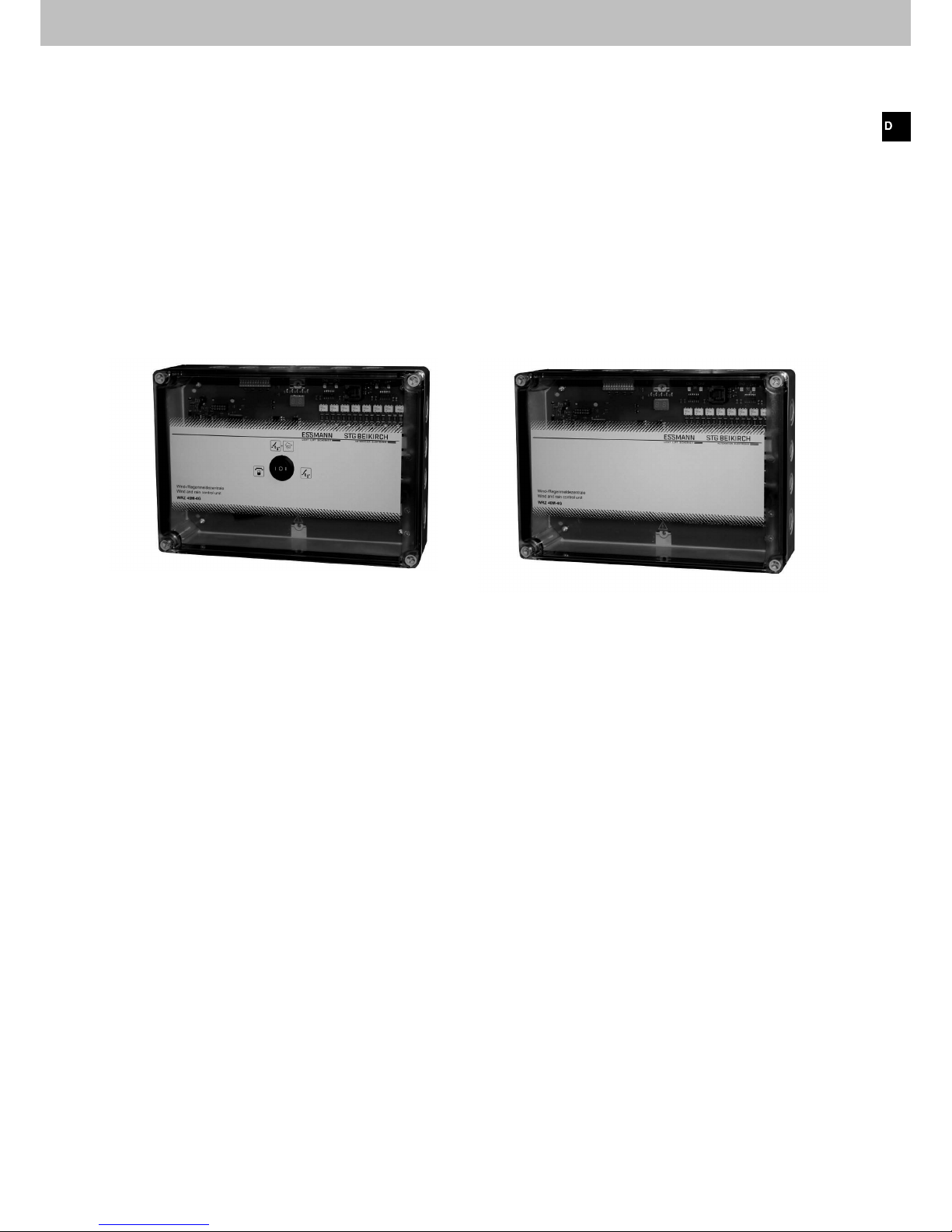
2.2 Besonderheiten
• Anschlussmöglichkeiten für 2 x Wind-/Regenmelder (Typ WRM/2 24 V) oder 2 x Regenmelder (Typ RM/2 24 V)
• Automatisches Schließen von Fenstern (Dach, Fassade), Lichtbänder oder Lichtkuppeln in Verbindung mit 230 V
AC Antrieben nach einer Wind-/Regenmeldung
• 1 x potenzialfreier Relaiskontakt zur Weiterleitung eines Wind-/Regensignals
• Kaskadierung von bis zu 4 Wind-/Regenmeldezentralen WRZ 40M-4G (Einstellung über DIP-Schalter)
• Optische Anzeigen von Statusmeldungen und Windgeschwindigkeit über 2 x 7 Segment Anzeige
• Getrennte LED-Anzeige einer Wind- und Regenmeldung
• LED-Anzeige für Netzversorgung
• Anschlussmöglichkeit eines 24 V Lüftungstasters (Einstellung über DIP-Schalter)
Der Antriebsausgang wird hierbei für 3 Minuten mit Spannung versorgt.
Funktion: manuelle Zentrallüftung (AUF / ZU) für alle 4 Antriebsgruppen zusammen
• Anschlussmöglichkeit eines 24 V Schlüsseltasters
Funktion: Zentral ZU für alle 4 Antriebsgruppen zusammen und Sperrung der manuellen Lüftungsfunktionen
• Ausführungsvarianten mit oder ohne Wahlschalter (ZU, AUTOMATIK, HAND), integriert im Gehäusedeckel
• Verschaltung mit 230 V Lüftungstaster
Funktion: manuelle Einzellüftung (AUF / ZU) pro Antriebsgruppe
• Ansteuerung von Magnetventilen für Pneumatikanlagen (Einstellung über DIP-Schalter)
Abb.: WRZ 40M-4G mit Wahlschalter im Gehäusedeckel Abb.: WRZ 40M-4G ohne Wahlschalter im Gehäusedeckel
Page 6

6 03/13424999503
Wind-/Regenmeldezentrale WRZ 40M-4G
2.3 Aufbau der Grundplatine und Anschlussmöglichkeiten
LED-Anzeigen
für Netzbetrieb
und Wind-/
Regenmeldung
LED-Anzeigen für die
Antriebsgruppen 3+4
LED-Anzeigen für die
Antriebsgruppen 1+2
Wahlschalter
(optional)
Relaiskontakt,
schaltet bei einer
Wind-/Regenmeldung
Wind-/Regenmelder oder
Regenmelder
24 V
Wind-/Regenmelder oder
Regenmelder
24 V
Lüftungstaster
24 V oder
Schlüsseltaster
24 V
Bus-Anschluss zur
Kaskardierung von
bis zu 4 Wind-Regenmeldezentralen
Netz
230 V AC
Antriebe
230 V AC
Antriebsgruppe 1
Antriebe
230 V AC
Antriebsgruppe 2
Antriebe
230 V AC
Antriebsgruppe 4
Antriebe
230 V AC
Antriebsgruppe 3
DIP-Schalter 1-12, zur
Einstellung verschiedener
Betriebskongurationen
2 x 7 Segment Anzeige für
Windgeschwindigkeit und
Betriebsstatus
1
6
7
7
5
4
4
3
2
Die WRZ 40M-4G Wind-/Regenmeldezentrale bietet Anschlussmöglichkeiten für:
1 x Lüftungstaster 24 V (z. B. Typ LTA 11) oder 1 x Schlüsseltaster 24 V (z. B. Typ LTA 12 oder LTA 13)
1 x Wahlschalter (optional)
Max. 40 Antriebe 230 V AC (z. B. Typ M3) verteilt auf 4 Antriebsgruppen, max. 2 A je Antriebsgruppe
1 x Bus-Anschluss zur Kaskardierung von bis zu 4 Wind-/Regenmeldezentralen
1 x potentialfreier Relaiskontakt zur Weiterleitung einer Wind-/Regenmeldung
2 x Wind-/Regenmelder WRM/2 24 V oder 2 x Regenmelder RM/2 24 V
1
6
7
5
4
3
2
Page 7
7
03/13424999503
Wind-/Regenmeldezentrale WRZ 40M-4G
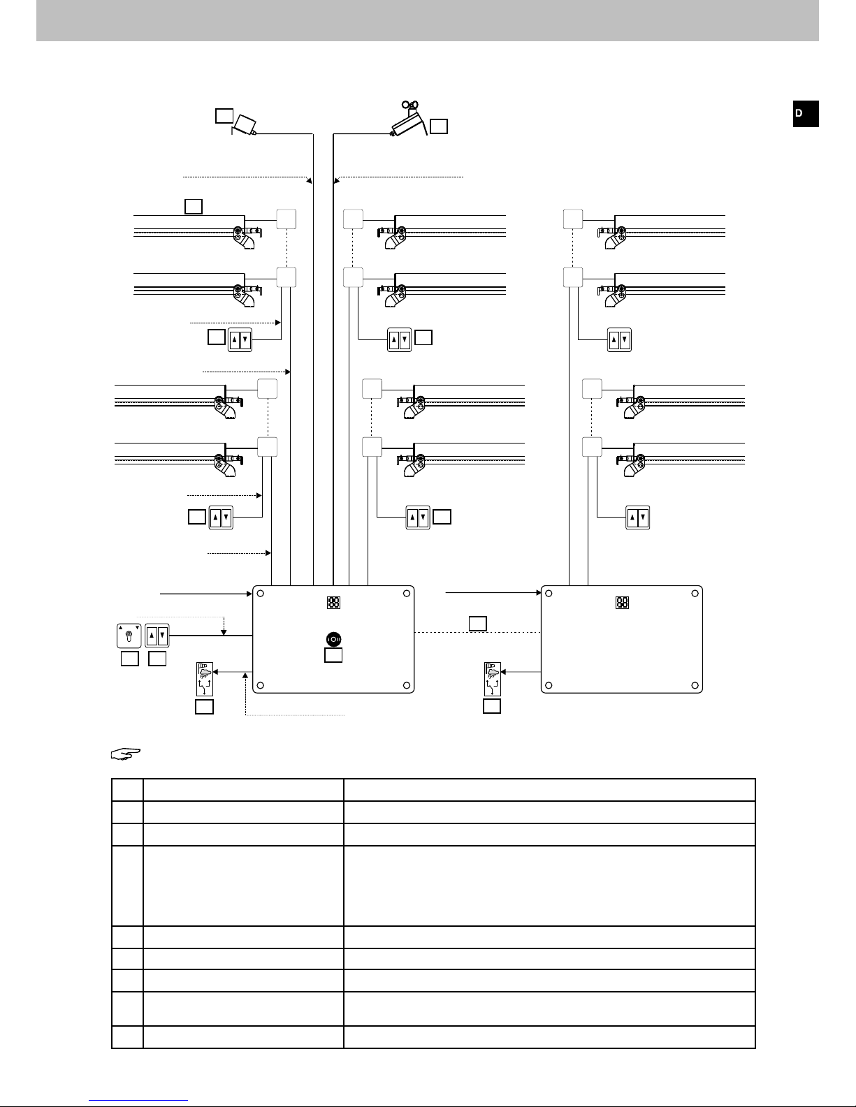
3 Musterverkabelungsplan
Hinweis: Es handelt sich hierbei um ein Verkabelungsbeispiel.
Nr.: Anschlussmöglichkeit Funktion
1 Lüftungstaster 24 V (optional) Zentrale Lüftungsfunktion AUF / ZU, wirkt auf alle 4 Antriebsgruppen
2 Schlüsseltaster 24 V (optional) Zentral ZU, wirkt auf alle 4 Antriebsgruppen (Sperrung der Lüftungsfunktion)
3 Wahlschalter integriert im Gehäuse-
deckel der WRZ 40M-4G (optional)
ZU(I) AUTOMATIK(O) HAND(II)
ZU: Alle Lüftungsaggregate fahren zu. Die manuelle Lüftung ist gesperrt.
AUTOMATIK: automatisches Schließen aller Lüftungsaggregate bei einer
Wind- oder Regenmeldung.
HAND: Lüftung AUF / ZU manuell über 24 V oder 230 V Lüftungstaster.
Die Wind-/ Regenmeldung ist gesperrt (Wartungsfunktion).
4 Lüftungsantriebe 230 V AC Öffnen und Schließen von Lichtkuppeln, Dach- und Fassadenfenster
5 Bus-Anschluss Zur Kaskadierung von bis zu 4 Wind-Regenmeldezentralen
6 Potenzialfreier Relaiskontakt Schaltet bei einer Wind-, Schnee- oder Regenmeldung
7 Wind-/Regenmelder WRM/2 24V
oder Regenmelder RM/2 24V
Meldung Wind, Regen oder Schnee über potenzialfreien Wechslerkontakt
an die Wind-/Regenmeldezentrale WRZ 40 M-4G
8 Lüftungstaster 230 V Einzellüftung AUF / ZU der Antriebsgruppen 1 - 4
H
A
Antriebsgruppe 2
(max. 2 A)
Antriebsgruppe 3
(max. 2 A)
Antriebsgruppe 1
(max. 2 A)
Antriebsgruppe 4
(max. 2 A)
min. NYM-J 5 x 1,5mm²
min. NYM-J 5 x 1,5mm²
min. NYM-J 5 x 1,5mm²
min. NYM-J 5 x 1,5mm²
Abzweigdose
WRZ 40M-4G
WRZ 40M-4G
(max. 4 Stck.
kaskadierbar)
bis 350 m J-Y(ST)Y 4 x 2 x 0,8mm²
bis 200 m J-Y(ST)Y 2 x 2 x 0,8mm²
bis 350 m J-Y(ST)Y 4 x 2 x 0,8mm²
1
6
6
7
7
5
8
8
8
8
4
3
2
IY (ST) Y 2 x 2 x 0,8mm²
IY (ST) Y 2 x 2 x 0,8mm²
Busleitung
IY (ST) Y 2 x 2 x 0,8mm²
Netz 230V AC
NYM-J 3 x 1,5mm²
Netz 230V AC
NYM-J 3 x 1,5mm²
Page 8

8 03/13424999503
Wind-/Regenmeldezentrale WRZ 40M-4G
4 Technische Daten
Elektrische Eigenschaften
Primäre Energieversorgung
Betriebsspannung: 230 V AC nenn (-10 % / +10 %)
Leistungsaufnahme: Max. 1860 W
Leistungsaufnahme (Stand-by): 1 W
Anschlussklemme: Max. 2,5 mm² Federklemme
Sicherung Steuerelektronik: Printsicherung 1,25 A/T TE5 250 V
Ausgang Antriebe
Spannung: 230 V AC nenn (-10 % / +10 %)
Nennstrom: 2 A pro Antriebsgruppe
Automatische Freischaltung: Dauer oder 2 Sek. Impuls (für Magnetventile), einstellbar
Anschlussklemme: Max. 2,5 mm² Federklemme
Sicherung: T 3,15 A H
Ausgang Wind-/Regenmelder
Spannung: 24 V nenn
Strom: Max. 500 mA, (Gesamtstrom 2 Wind-/Regenmelder)
Anschlussklemme: Max. 1,5 mm² Federklemme
Max. Anzahl: 2 Stück, Typ WRM/2 / RM/2
Sicherung: Keine
Mechanische Eigenschaften
Maße (B x H x T): 250 x 175 x 75 mm, ohne Verschraubungen
Gewicht: Ca. 1 kg
Gehäuse: Polycarbonat
Farbe: Grau, Deckel transparent
Halogenfrei: Ja
Silikonfrei: Ja
RoHS konform: Ja
Einstellbare Funktionen
Konfigurierung: Ja, durch DIP-Schalter
Möglichkeiten: - Lüftung über Lüftungstaster 24 V
- Auslöseschwelle der Windgeschwindigkeit
- Spannungsausgang: Dauer oder Impuls
- Verschaltung von bis zu 4 Wind-/Regenmeldezentralen
Einbau und Umgebungsbedingungen
Zulässiger Temperaturbereich (Betrieb): -5 °C bis 40 °C
Zulässiger Temperaturbereich (Lagerung/Transport): -25 °C bis 75 °C
Zulässige Luftfeuchtigkeit (Betrieb/Lagerung/Transport): 10 % bis 95 %
Geeignet für Außenmontage: Nein
Schutzart: IP 66 (Gehäuse) WRZ 40M-4G ohne Wahlschalter
IP 54 (Gehäuse) WRZ 40M-4G mit Wahlschalter
Zulassungen und Nachweise
CE-konform: Gemäß EMV-Richtlinie 2014/30/EU und der
Niederspannungsrichtlinie 2014/35/EU
Page 9

9
03/13424999503
Wind-/Regenmeldezentrale WRZ 40M-4G
5 Montage
Hinweis: Die Sicherheitshinweise auf Seite 3 müssen
beachtet werden.
Für die Montage der WRZ 40M-4G Wind-/Regenmeldezentrale
einen trockenen Raum auswählen.
Für die Montage der Lüftungstaster gut sichtbare und erreichbare
Orte aussuchen.
5.1 Montageablauf
► Zentrale öffnen und zuerst die Grundplatine mit Steuerelektronik
aus dem Kunststoffgehäuse ausbauen.
Dazu die 4 Befestigungsschrauben auf der Grundplatine lösen.
► Kabeleinführungen am Kunststoffgehäuse ausbrechen.
Dabei die Ansetzpunkte für den Schraubendreher an den
Sollbruchstellen gemäß Bildanleitung beachten.
► Kunststoffgehäuse mit geeigneten Dübel und Schrauben an der
Wand befestigen.
► Grundplatine mit Steuerelektronik wieder einbauen.
Abb.: Bildanleitung Ausbrechen Kabeleinführung am Kunststoffgehäuse
Abb.: Maße Befestigungsbohrungen für Wandmontage
Abb.: WRZ 40M-4G mit Grundplatine
Ansetzpunkte für Schraubendreher
Grundplatine
Befestigungsschrauben
235
11
160
Ø 4,5
Ø 8,5
Grundplatine
Page 10
10 03/13424999503
6 Elektrische Anschlüsse
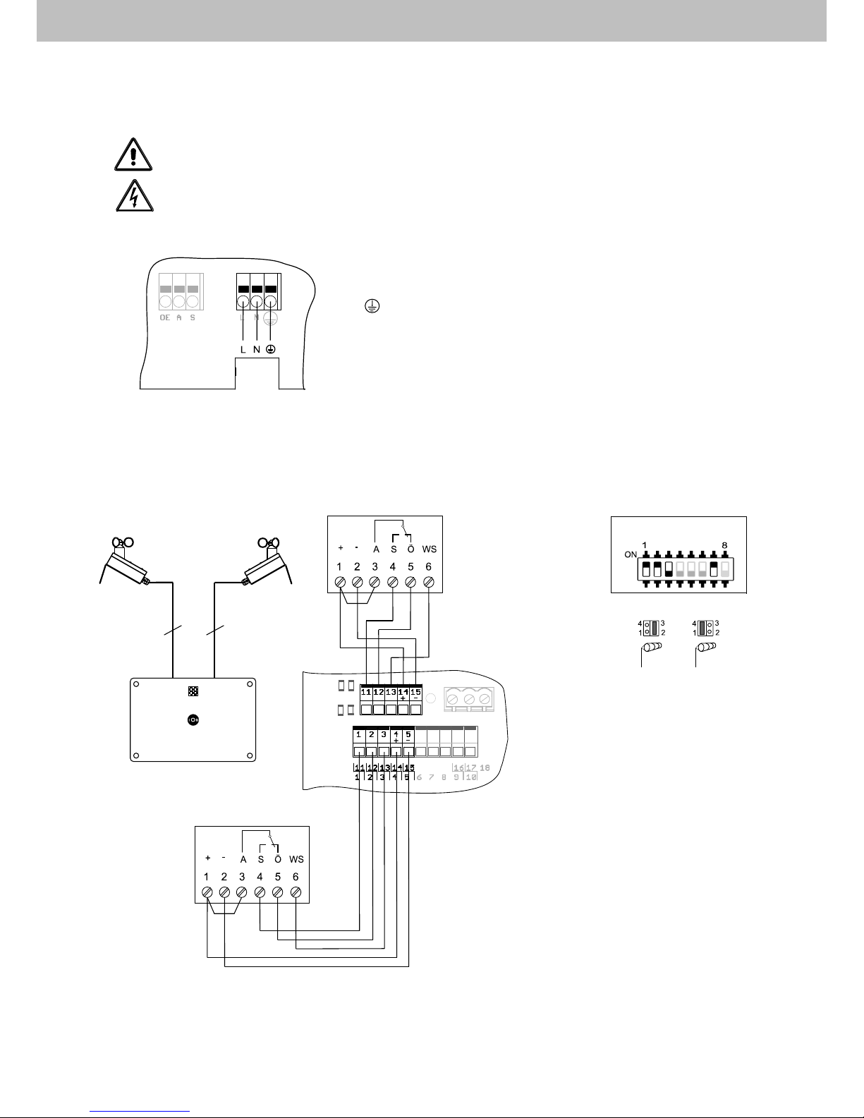
6.1 Anschluss Netz 230 V AC
Achtung! Vor Arbeiten an der Anlage ist die Netzspannung allpolig freizuschalten und gegen
unbeabsichtigtes Widereinschalten zu sichern.
Vorsicht! Unsachgemäßes Arbeiten an spannungsführenden Bauteilen kann zu einem Stromschlag führen!
Der elektrische Anschluss muss durch ausgewiesenes Elektrofachpersonal durchgeführt werden.
6.2. Anschluss Wind-/Regenmelder WRM/2 24V
Wind-/Regenmeldezentrale WRZ 40M-4G
11 12 13 14 15
55
L = Phase
N = Neutralleiter
= Schutzleiter (PE)
Netzzuleitung
230 V AC
1: Spannungsversorgung +24 V DC
2: Spannungsversorgung -24 V DC
3: Relaiskontakt (Arbeitskontakt)
4: Relaiskontakt (Schließer)
5: Relaiskontakt (Öffner) oder
Windsensor Signal
6: Windsensor Signal
Klemmenbezeichnung DIP-Schalter und Jumper
im WRM/2 24V Einstellung im WRM/2 24V
2. WRM/2 24V
2. WRM/2 24V
1. WRM/2 24V
1. WRM/2 24V
DIP-Schalter
Windsensor
Jumper 1+4
zur Anzeige
der Wind-
geschwindigkeit
WRZ 40M-4G
Jumper
Page 11

11
03/13424999503
6.2.1 Anschluss Regenmelder RM/2 24V
6.3 Direkter Anschluss der Antriebe 230 V und Lüftungstaster 24 V
Wind-/Regenmeldezentrale WRZ 40M-4G
WRZ 40M-4G
ZU N AUF.PE
ZU N AUF.PE
ZU N AUF.PE
ZU N AUF.PE
Hinweis: DIP-Schalter 1 muss auf ON
gesetzt werden.
Antriebsgruppe 3
Antriebsgruppe 1
Hinweis: Darstellung mit und ohne PE-Anschluss am Antrieb
Antriebsgruppe 4
Antriebs-
gruppe 2
Antriebe 230 V
I = max. 2 A
pro Antriebsgruppe
Antriebe 230 V
I = max. 2 A
pro Antriebsgruppe
Antriebe 230 V
I = max. 2 A
pro Antriebsgruppe
Antriebe 230 V
I = max. 2 A pro
Antriebsgruppe
ZU AUF
PE PEPE PE
Lüftungstaster 24 V
Abzweigdose
1 2 3 4 5 6 7 8 9 10 1112
11 12 13 14 15
33
1: Spannungsversorgung +24 V DC
2: Spannungsversorgung -24 V DC
3: Relaiskontakt (Arbeitskontakt)
4: Relaiskontakt (Schließer)
Klemmenbezeichnung DIP-Schalter Einstellung
im RM/2 24V im RM/2 24V
WRZ 40M-4G
1. RM/2 24V
1. RM/2 24V
2. RM/2 24V
2. RM/2 24V
Page 12

12 03/13424999503
Wind-/Regenmeldezentrale WRZ 40M-4G
6.3.1 Anschluss Antriebe 230 V mit Lüftungstaster 230 V und
Schlüsseltaster 24 V
Schlüsseltaster 24 V
Lüftungstaster
230 V
Lüftungstaster
230 V
Lüftungstaster
230 V
Lüftungstaster
230 V
WRZ 40M-4G
Antriebe 230 V
I = max. 2 A pro
Antriebsgruppe
Antriebe 230 V
I = max. 2 A pro
Antriebsgruppe
Antriebe 230 V
I = max. 2 A pro
Antriebsgruppe
Antriebe 230 V
I = max. 2 A pro
Antriebsgruppe
ZU N AUF.PE
ZU N AUF.PE
ZU N AUF.PEZU N AUF.PE
Antriebsgruppe 3
Antriebsgruppe 1
Hinweis: Darstellung mit und ohne PE-Anschluss am Antrieb
Antriebsgruppe 4
Antriebsgruppe 2
Abzweigdose
ZU
ZU
ZU
ZU
ZU
AUF AUF
AUF
AUF
Page 13
13
03/13424999503
Wind-/Regenmeldezentrale WRZ 40M-4G
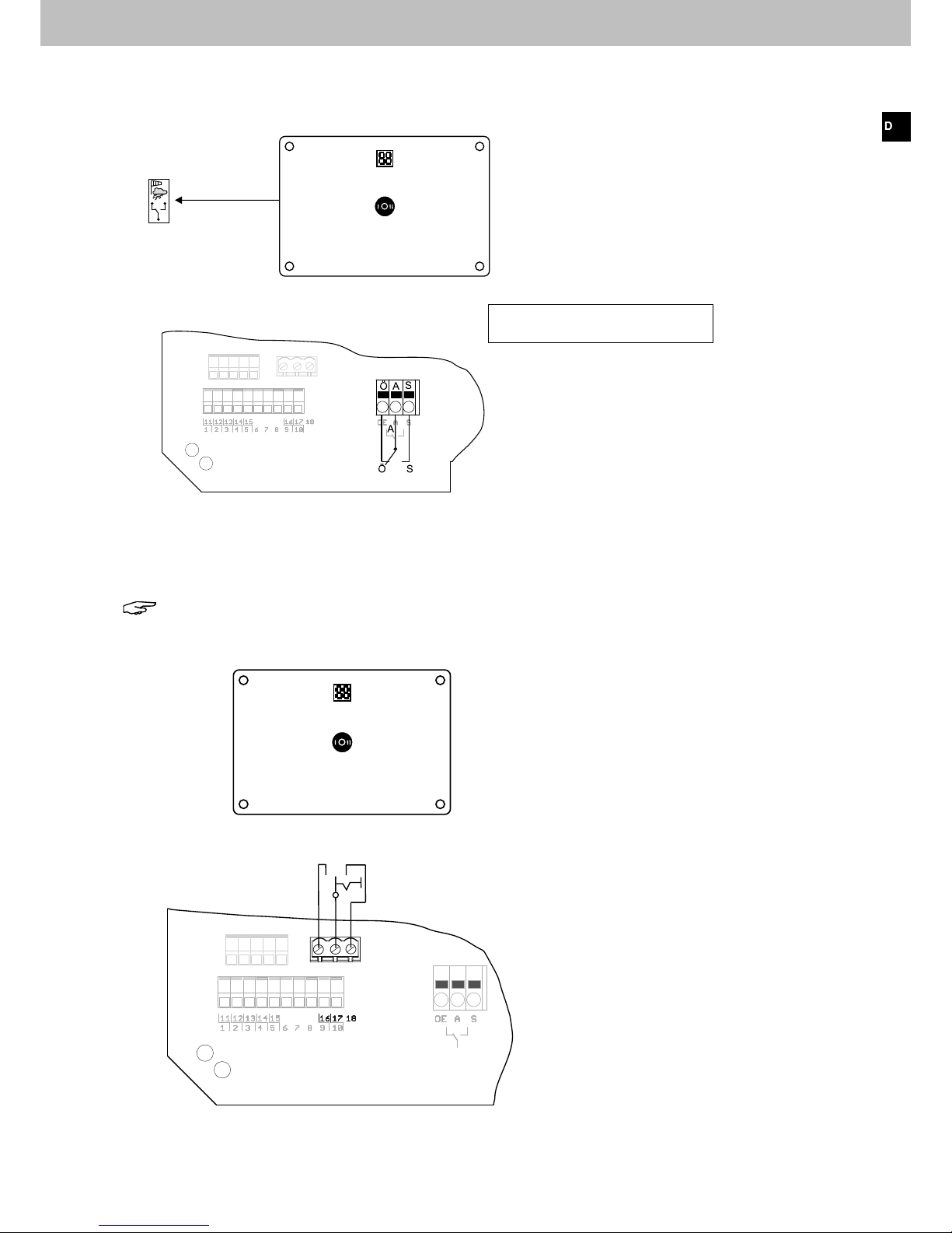
6.4 Anschluss potenzialfreier Kontakte
Potenzialfreie Kontakte zur Weiterleitung der Wind-/Regenmeldung
6.5 Anschluss Wahlschalter ZU (I) / AUTOMATIK (O) / HAND (II)
Hinweis: Werden die Klemmen 16, 17 und 18 nicht verschaltet, so ist die Funktton "AUTOMATIK" aktiv.
Wahlschalter
Wahlschalter
AUTOMATIK
H
A
Kontaktbelastung: 230 V / max. 2 A
16 17 18
I O II
HAND
ZU
Page 14

14 03/13424999503
6.6 Anschluss 4 x Wind-/Regenmeldezentralen (Master/Slave Betrieb),
1 x Schlüsseltaster 24 V und DIP-Schalter Einstellung
Die WRZ 40M-4G bietet die Möglichkeit 3 weitere Zentralen durch eine Busleitung anzuschließen. Das ermöglicht einen
Master/Slave Betrieb. Die Hauptzentrale ist der Master. Sie erteilt Befehle an alle weiteren Slave-Zentralen über eine
Busleitung. Auch die Wind-/Regenmeldung wird über die Busleitung an die Slave-Zentralen weitergeleitet.
Jede Zentrale muss mit Energie (230 V AC) versorgt werden. An den Slave-Zentralen müssen individuelle DIP-Schalter
Einstellungen vorgenommen werden. Über einen Schlüsseltaster 24 V, der an der Masterzentrale angeschlossen wird,
können alle angeschlossenen Antriebe (230 V) zentral ZU gefahren werden.
Hinweis: Die Antriebe fahren nur solange ZU, wie der Schlüsseltaster betätigt und gehalten wird. Bei
Nichtbetätigung stoppen die Antriebe.
Um die Antriebe wieder auffahren zu können, werden Lüftungstaster 230 V in jeder Antriebsgruppe verschaltet.
1 2 3 4 5 6 7 8 9 10 11 12 1 2 3 4 5 6 7 8 9 1011 12
1 2 3 4 5 6 7 8 9 10 11 12
Zentrale 1 (Master)
Zentrale 1 (Master) Zentrale 2 (Slave)
Zentrale 2 (Slave) Zentrale 3 (Slave)
Zentrale 3 (Slave)
Zentrale 4 (Slave)
Zentrale 4 (Slave)
Schlüsseltaster 24 V
Schlüsseltaster 24 V
Busleitung
Busleitung
Busleitung
Busleitung
230 V AC
230 V AC
230 V AC 230 V AC
Bus Bus
Antriebe 230 V
Antriebe 230 V
Antriebe 230 V
Lüftungs-
taster 230 V
Lüftungs-
taster 230 V
Lüftungs-
taster 230 V
Antriebe 230 V
DIP-Schalter
8 = ON
DIP-Schalter
6 = ON
8 = ON
DIP-Schalter
7 = ON
8 = ON
ZU
Wind-/Regenmelder
Regenmelder
Wind-/Regenmeldezentrale WRZ 40M-4G
Page 15

15
03/13424999503
6.7 Anschluss 4 x Wind-/Regenmeldezentralen (Master/Slave Betrieb),
1 x Lüftungstaster 24 V und DIP-Schalter Einstellung
Die WRZ 40M-4G bietet die Möglichkeit 3 weitere Zentralen durch eine Busleitung anzuschließen. Das ermöglicht einen
Master/Slave Betrieb. Die Hauptzentrale ist der Master. Sie erteilt Befehle an alle weiteren Slave-Zentralen über eine
Busleitung. Auch die Wind-/Regenmeldung wird über die Busleitung an die Slave-Zentralen weitergeleitet.
Jede Zentrale muss mit Energie (230 V AC) versorgt werden. An den Slave-Zentralen müssen individuelle DIP-Schalter
Einstellungen vorgenommen werden. Über einen Lüftungstaster 24 V, der an der Masterzentrale angeschlossen wird,
können alle Antriebe (230 V) zentral AUF und ZU gefahren werden. Hierfür muss an der Master-Zentrale der DIP-Schalter 1 gesetzt werden.
Bei diesem Anschlussbeispiel können die Antriebe direkt (ohne Lüftungstaster 230 V) an den Klemmen ZU, N, AUF
der Zentrale angeschlossen werden.
Nach Betätigung des Lüftungstasters werden die Anschlussklemmen für die Antriebe (ZU oder AUF) für 3 Minuten mit
Spannung versorgt. Danach liegt keine Spannung mehr an.
1 2 3 4 5 6 7 8 9 10 1112 1 2 3 4 5 6 7 8 9 10 1112
1 2 3 4 5 6 7 8 9 10 1112
1 2 3 4 5 6 7 8 9 10 1112
Zentrale 1 (Master)
Zentrale 1 (Master) Zentrale 2 (Slave)
Zentrale 2 (Slave) Zentrale 3 (Slave)
Zentrale 3 (Slave)
Zentrale 4 (Slave)
Zentrale 4 (Slave)
Lüftungstaster 24 V
Lüftungstaster 24 V
Busleitung
Busleitung
Busleitung
Busleitung
230 V AC 230 V AC 230 V AC 230 V AC
Bus Bus
Antriebe 230 V Antriebe 230 V Antriebe 230 V Antriebe 230 V
DIP-Schalter
1 = ON
DIP-Schalter
8 = ON
DIP-Schalter
6 = ON
8 = ON
DIP-Schalter
7 = ON
8 = ON
ZUAUF
Wind-/Regenmelder
Regenmelder
Wind-/Regenmeldezentrale WRZ 40M-4G
Page 16

16 03/13424999503
Wind-/Regenmeldezentrale WRZ 40M-4G
7 DIP-Schalter Funktionen
Kombinationen verschiedener DIP-Schalter Einstellungen sind möglich z. B. DIP-Schalter 3 = ON und 4 = ON.
Werkseitig befinden sich alle DIP-Schalter in Stellung OFF (Aus). Stellung ON (Ein) bedeutet:
DIP-Schalter 1: Lüftung über Lüftungstaster 24 V
Bei angeschlossenen 24 V Lüftungstaster können alle Antriebsgruppen gleichzeitig AUF oder ZU gefahren werden.
Der Antriebsausgang (ZU oder AUF) wird nach Betätigung des Lüftungstasters für 3 Minuten mit Spannung versorgt.
Danach spannungsfrei.
Achtung: Die Antriebe müssen direkt, ohne 230 V Lüftungstaster, an den
Klemmen der WRZ 40M-4G angeschlossen werden.
DIP-Schalter 2: Einstellung der Einschaltverzögerung
Verzögerungszeit einer anstehenden Auslöse-Windgeschwindigkeit bis die Anlage die Lüftungsaggregate schließt.
ON OFF
20 Sekunden 10 Sekunden
DIP-Schalter 3, 4: Einstellung der Auslöseschwelle der Windgeschwindigkeit
ON OFF Windgeschwindigkeit DIP-Schalter Einstellung
3 + 4: > 15 m/s
3 + 4 > 7 m/s
4 3 > 10 m/s
3 4 > 13 m/s
DIP-Schalter 6, 7, 8: Einstellung der DIP-Schalter zur Verschaltung mehrerer Zentralen
ON OFF Einstellung in Zentrale DIP-Schalter Einstellung
6 + 7
+ 8
Zentrale 1 (Master)
8 6 + 7 Zentrale 2 (Slave 1)
6 + 8 7 Zentrale 3 (Slave 2)
7 + 8 6 Zentrale 4 (Slave 3)
1 2 3 4 5 6 7 8 9 1011 12
1 2 3 4 5 6 7 8 9 1011 12
1 2 3 4 5 6 7 8 9 101112
ON
1 2 3 4 5 6 7 8 9 1011 12
1 2 3 4 5 6 7 8 9 1011 12
1 2 3 4 5 6 7 8 9 1011 12
1 2 3 4 5 6 7 8 9 1011 12
1 2 3 4 5 6 7 8 9 1011 12
1 2 3 4 5 6 7 8 9 1011 12
Page 17

17
03/13424999503
Wind-/Regenmeldezentrale WRZ 40M-4G
DIP-Schalter 9: Ansteuerung von Magnetventilen in Pneumatikanlagen
Die Antriebsgruppen werden nach einem Zustandswechsel in Richtung AUF bzw. ZU impulsartig für die Dauer
von 2 Sek. mit Spannung versorgt.
DIP-Schalter 5, 10, 11, 12: Einstellung der Status- und Windgeschwindigkeitsanzeige (2 x 7 Segment Anzeige)
ON OFF Funktion DIP-Schalter Einstellung
5
Anzeige der Windgeschwindigkeit.
Dies dient zur Anpassung der Anzeige bei
180° Einbau der Platine zwecks Änderung
der Kabelführung von unten nach oben
5
Normalbetrieb, Anzeige der
Windgeschwindigkeit (z. B: 13 m/s)
10
Anzeige der aktuellen Windgeschwindigkeit.
Bei null wird 0 m/s angezeigt. Bei Betätigung des Wahlschalters wird der aktuelle Status (HAND/AUTO/ZU) für ca.15 Sek.
angezeigt, dann wieder die aktuelle Windgeschwindigkeit
10
Die aktuelle Windgeschwindigkeit wird angezeigt, wenn
größer als null. Sonst wird der aktuelle Status
(ZU/AUTOMATIK/HAND) angezeigt
11 + 12
Anzeige der Windgeschwindigkeit vom Wind-/Regenmelder 1
11 12
Anzeige der Windgeschwindigkeit vom Wind-/Regenmelder 2
11 + 12
Abwechselnde Anzeige der Windgeschwindigkeit vom Wind-/
Regenmelder 1 und 2
12 11
Anzeige Fehler „E“ = „Error",
Kombinationsfehler in der
DIP-Schalter Einstellung
7.1 Aktivierung der DIP-Schalter Funktionen
Achtung! Zuerst die Zentrale vom Netz trennen, dann Einstellung bzw. Änderung am DIP-Schalter vornehmen.
Nach Beendigung der Einstellungen am DIP-Schalter erfolgt das Einschalten oder Anklemmen der 230 V AC
Netzspannung. Die geänderten Konfigurationen werden dann in den Speicher übernommen.
1 2 3 4 5 6 7 8 9 1011 12
1 2 3 4 5 6 7 8 9 1011 12
1 2 3 4 5 6 7 8 9 1011 12
Windgeschwindigkeit
ZU (CLOSED)
AUTOMAT IK HAND
1 2 3 4 5 6 7 8 9 1011 12
1 2 3 4 5 6 7 8 9 1011 12
1 2 3 4 5 6 7 8 9 1011 12
Page 18

18 03/13424999503
Wind-/Regenmeldezentrale WRZ 40M-4G
8 Betriebsarten des Wahlschalters (I, O, II)
Die Wind-/Regenmeldezentrale bietet 3 Betriebsarten, die mittels optionalem Wahlschalter
ausgewählt werden können. Ohne Wahlschalter ist der Automatikbetrieb eingestellt.
AUTOMATIK-Betrieb (O)
Angeschlossene Lüftungsaggregate können manuell zum Lüften über Lüftungstaster auf- und zugefahren werden. Bei
hohen Windgeschwindigkeiten, Regen oder Schnee werden alle angeschlossenen Lüftungsaggregate automatisch
geschlossen. Die manuelle Lüftungsfunktion wird erst wieder freigegeben wenn:
• kein Regen oder Schnee mehr festgestellt wird und die Sensorfläche vollständig abgetrocknet ist
• die Windgeschwindigkeit kleiner der eingestellten Auslösegeschwindigkeit ist
• die Zeitverzögerung (ca. 10 Sekunden) abgelaufen ist.
Ein automatisches Auffahren der Lüftungsaggregate ist aus Sicherheitsgründen nicht vorgesehen.
HAND-Betrieb (II)
In der Schalterstellung "HAND" ist Automatik zum Schließen der Fenster außer Betrieb. Die Lüftungsaggregate können
über Lüftungstaster manuell geöffnet und geschlossen werden. Ein automatisches Schließen bei hohen
Windgeschwindigkeiten, Regen oder Schnee geschieht nicht.
ZU-Betrieb (I)
Alle angeschlossenen Lüftungsaggregate werden geschlossen. Die manuelle Lüftung ist gesperrt.
9 Inbetriebnahme
Test HAND-Betrieb (II)
Nach dem elektrischen Anschluss aller externen Komponenten:
► Netzzuleitung der Zentrale aufschalten (L, N, PE).
LED Nr. 1 leuchtet GRÜN.
► Wahlschalter auf "HAND" Betrieb stellen (II).
Die Automatikfunktion der Wind- und Regenmeldezentrale ist außer Betrieb.
Fenster können über Lüftungstaster manuell auf und zugefahren werden.
Ein Schließen bei Wind und Regen geschieht nicht.
LEDs für angeschlossene Antriebsgruppen (CH1 bis CH4) leuchten ROT.
Antriebe fahren die Fenster AUF, wenn ein Lüftungstaster in AUF-Richtung betätigt wird.
Sie leuchten GRÜN bei Betätigung eines angeschlossenen Lüftungstasters
oder Schlüsseltasters in ZU-Richtung.
Test AUTOMATIK-Betrieb (O) am Regenmelder
LED Nr. 1 leuchtet GRÜN.
► Wahlschalter auf "AUTOMATIK" Betrieb stellen (O).
LEDs für angeschlossene Antriebsgruppen (CH1 bis CH4) leuchten ROT.
Antriebe fahren die Fenster AUF, wenn ein Lüftungstaster in AUF-Richtung betätigt wird.
► Regensensorfläche mit Wasser benetzen.
LED Nr. 3 leuchtet GELB bei Auslösung von Regenmelder 1.
LED Nr. 5 leuchtet GELB bei Auslösung von Regenmelder 2.
Fenster fahren ZU.
LEDs für angeschlossenen Antriebsgruppen (CH1 bis CH4) leuchten GRÜN.
Antriebsgruppe 1 = Channel 1 = Ch1
Antriebsgruppe 2 = Channel 2 = Ch2
Antriebsgruppe 3 = Channel 3 = Ch3
Antriebsgruppe 4 = Channel 4 = Ch4
Abb.: LED 1 leuchtet grün
Abb.: LED 3 und oder 5 leuchten gelb
Abb.: LEDs für angeschlossene Antriebsgruppen Ch1 bis Ch4
Page 19

19
03/13424999503
Wind-/Regenmeldezentrale WRZ 40M-4G
Test AUTOMATIK-Betrieb (O) am Windmelder
LED Nr. 1 leuchtet GRÜN.
► Wahlschalter auf "AUTO" Betrieb stellen.
LEDs Nr. 3 und Nr. 5 sind aus (Sensoren sind nicht ausgelöst).
LEDs für angeschlossene Antriebsgruppen (CH1 bis CH4) leuchten ROT.
Antriebe fahren die Fenster AUF, wenn ein Lüftungstaster in AUF-Richtung betätigt wird.
►Windmelder mit Wind beaufschlagen.
LED Nr. 2 leuchtet GELB bei Auslösung von Windmelder 1.
LED Nr. 4 leuchtet GELB bei Auslösung von Windmelder 2.
Fenster fahren ZU.
LEDs für angeschlossenen Antriebsgruppen leuchten GRÜN.
Test ZU-Betrieb (I)
LED Nr. 1 leuchtet GRÜN.
LEDs für angeschlossene Antriebsgruppen (CH1 bis CH4)
leuchten ROT.
Antriebe fahren die Fenster AUF, wenn ein Lüftungstaster in
AUF-Richtung betätigt wird.
► Wahlschalter auf "ZU" Betrieb stellen (I)
Fenster fahren ZU und können nicht über die Lüftungstaster
aufgefahren werden.
LEDs für angeschlossenen Antriebsgruppen leuchten GRÜN.
10 LED-Anzeigen
LED-Anzeigen für die Antriebsgruppen Ch1, Ch2, Ch3, Ch4
LED-Anzeige
Ch1 bis Ch4
Status Anschlussklemmen
(ZU, AUF) Channel 1 -4
Status Antrieb
leuchtet ROT Spannung an AUF-Klemme Antrieb fährt AUF
leuchtet GRÜN Spannung an ZU-Klemme Antrieb fährt ZU
AUS Spannungsfrei Antrieb STOP
LED-Anzeigen für die Wind-/Regenmeldung
LED-Nr. LED-Anzeige Status
1 leuchtet GRÜN Netzbetrieb
2 leuchtet GELB Auslösung Windmelder 1: Zu hohe Windgeschwindigkeit
3 leuchtet GELB Auslösung Regenmelder 1: Meldung Regen oder Schnee
4 leuchtet GELB Auslösung Windmelder 2: Zu hohe Windgeschwindigkeit
5 leuchtet GELB Auslösung Regenmelder 2: Meldung Regen oder Schnee
Abb.: LED 2 und oder 4 leuchten gelb
Abb.: LEDs für angeschlossene Antriebsgruppen Ch1 bis Ch4
Abb.: LED 1 leuchtet grün
Page 20

20 03/13424999503
Wind-/Regenmeldezentrale WRZ 40M-4G
11 Störungshilfen
Problem Mögliche Ursachen Abhilfe
Klappen fahren bei Regen/
Schneefall nicht zu
• Defekte oder falsch angeschlossene
Anschlussleitungen
• DIP-Schalter im Wind-/Regenmelder falsch
eingestellt
• Wahlschalter steht auf "HAND"
• Anschlussleitungen kontrollieren ggf.
richtig anschließen
• DIP-Schalter im Wind-/Regenmelder nach
Anleitung richtig einstellen (siehe Anschluss
WRM/2, RM/2, Seite 10, 11)
• Wahlschalter auf "AUTOMATIK" stellen
Klappen fahren bei starkem
Wind nicht zu
• Defekte oder falsch angeschlossene
Anschlussleitungen
• DIP-Schalter im Wind-/Regenmelder falsch
eingestellt (Windauslösung deaktiviert)
• Auslöseschwelle der Windgeschwindigkeit
zu hoch
• Wahlschalter steht auf "HAND"
• Anschlussleitungen kontrollieren ggf.
richtig anschließen
• DIP-Schalter nach Anleitung richtig einstellen (siehe Anschluss WRM/2, Seite 10)
• Auslöseschwelle der Windgeschwindigkeit
verkleinern (Siehe DIP-Schalter 3, 4,
Seite 16)
• Wahlschalter auf "AUTOMATIK" stellen
Lüftungstaster mit umgekehrter
Funktion
• Gedrehter Anschluss am Lüftungstaster
oder der Wind-/Regenmeldezentrale.
• Anschluss kontrollieren und ggf. richtig
anschließen
Klappen öffnen sich nicht • Keine Netzspannung
• Wahlschalter in ZU-Stellung
• Eine Wind-/Regenmeldung steht an
• Netzspannung prüfen
• Wahlschalter in HAND-Stellung stellen
Schlüsseltaster ohne Funktion • Schlüsseltaster falsch angeschlossen
• Keine Netzspannung
• Anschluss kontrollieren und ggf. richtig
anschließen
• Netzspannung prüfen
12 Maßzeichnung
1)
Je nach Ausführung mit oder ohne integriertem Wahlschalter
250
75
5 x 30 = 150
175
235
11
1)
24
160
30
100
Ø 4,5
Ø 8,5
24
Page 21

21
03/13424999503
Wind-/Regenmeldezentrale WRZ 40M-4G
13 Windstärken nach Beaufort
Windstärke
nach Beaufort
Merkmal Geschwindigkeit
m/s
km/h Staudruck 2)
Pa=N/m²
0 Stille 0 - 0,2 Unter 1 0 - 0,2
1 leiser Zug 0,3 - 1,5 1 - 5 0,06 - 1,4
2 leichte Brise 1,6 - 3,3 6 - 11 1,6 - 6,8
3 schwache Brise 3,4 - 5,4 12 - 19 7,2 - 18,2
4 mäßige Brise 5,5 - 7,9 20 - 28 18,9 - 39,0
5 frische Brise 8,0 - 10,7 29 - 38 40 - 71,6
6 starke Brise 10,8 - 13,8 39 - 49 72,9 - 119,0
7 steifer Wind 13,9 - 17,1 50 - 61 120,8 - 182,8
8 stürmischer Wind 17,2 - 20,7 62 - 74 184,9 - 267,8
9 Sturm 20,8 - 24,4 75 - 88 270,4 - 372,1
10 schwerer Sturm 24,5 - 28,4 89 - 102 375,2 - 504,1
11 orkanartiger Sturm 28,5 - 32,6 103 - 117 507,7 - 664,2
12 Orkan 32, 7 u. mehr 118 u. mehr 668,3 u. mehr
2)
Die Staudruck-Angaben wurden vereinfacht berechnet
(P = Staudruck, V in m/s, P = V²/1,6 /PA = N/m²)
Page 22

Datei: Ti_WRZ_40M-4G_D_GB.indd / Ausgabe 03 / 29.09.2016 / Art.Nr. 13424999503
Hersteller: STG-BEIKIRCH Industrieelektronik + Sicherheitstechnik GmbH & Co. KG • Trifte 89 • D-32657 Lemgo • info@STG-BEIKIRCH.de • www.STG-BEIKIRCH.de
Wind and rain detection system WRZ 40M-4G
Page
1 General information and safety
instructions..........................................................................................................
2 Product description.......................................................................................................................................................
2.1 Function..........................................................................................................................................................
2.2 Special features......................................................................................................................................
2.3 Structure of the circuit board and connection options................................................................................
3 Model cable plan...................................................................................................................................................
4 Technical data.......................................................................................................................................................
5 Installation......................................................................................................................................................................
5.1 Installation process.................................................................................................................................
6 Electrical connection.....................................................................................................................................................
6.1 Connection mains 230 V AC.........................................................................................................................
6.2 Connection wind/rain detector WRM/2 24V.................................................................................................
6.2.1 Connection rain detector RM/2 24V..............................................................................................
6.3 Direct connection drives 230 V and vent switch 24 V.............................................................................
6.3.1 Connection drives 230 V with and vent switch 230 V and key switch 24 V..............................
6.4 Connection potential-free contacts.........................................................................................................
6.5 Connection selector switch CLOSE (I) / AUTOMATIC (O) / HAND (II)...................................................
6.6 Connection 4 x Wind/rain control units (master/slave operation), 1 x key switch 24 V and
DIP switch settings..................................................................................................................................
6.7 Connection 4 x Wind/rain control units (master/slave operation), 1 x vent switch 24 V and
DIP switch settings..................................................................................................................................
7 DIP switch settings................................................................................................................................................
7.1 Activating the DIP switch functions.........................................................................................................
8 Operating modes of the selector switch (I, O, II)...................................................................................................
9 Start up procedure.................................................................................................................................................
10 LED displays.........................................................................................................................................................
11 Troubleshooting.....................................................................................................................................................
12 Dimensional drawing.............................................................................................................................................
13 Beaufort wind scale...............................................................................................................................................
Content
23
25
25
25
26
27
28
29
29
30
30
30
31
31
32
33
33
34
35
36
37
38
38
39
40
40
41
Page 23

23
03/13424999503
Wind and rain detection system WRZ 40M-4G
1 General information
and safety instructions
Documentation: This documentation is exclusively valid
for the product or product range as stated in the type designation on the cover and must be applied comprehensively. This technical documentation must be read carefully
before installation. Follow the guidelines. Contact the
manufacturer if you have any questions or problems. This
documentation should be retained for future reference.
Subject to technical modifictionsDiagram is not binding.
User: This documentation is aimed at trained, professional
electricians with safety awareness, who are familiar with
mechanical and electrical equipment installation, accident
prevention regulations and industrial compensation laws,
and contains important information for operators and
users.
Please observe the following safety instructions which are
emphasized by special symbols.
Caution: Danger to persons due to electricity.
Attention: Danger to persons due to risks arising
from the operation of the equipment.
Danger of crushing/trapping.
Warning: Non-observance leads to destruction.
Danger to material due to incorrect handling.
Important information
Use according to regulations: The product may
only be used for the functions and applications
detailed, and in accordance with the accompanying
documentation. Unauthorised electrical and mechanical
modifications are not permitted and will invalidate warranty and liability.
Transport and storage: The product may only be transported and stored in its original packaging. It must not be
knocked, dropped, or exposed to moisture, aggressive
vapours or harmful environments. More detailed transport
and storage instructions provided by the manufacturer
must be observed.
Installation: Installation and assembly may only be carried
out by trained professional electricians, in accordance
with the recognised rules of engineering as well as the
technical documentation provided here. This will guarantee that the product will function safely during operation.
Care should be taken that all mechanical components
are fixed. Immediately after installation the electrical and
mechanical components should be checked to ensure
that they function correctly, and the tests and the results
thereof should be documented.
Operation: Safe operation is guaranteed if the acceptable rated values and guidelines regarding maintenance
information stated in this documentation, as well as
supplementary information provided by the manufacturer,
are followed.
Malfunction: If a malfunction is identified in the course of
installation, maintenance, inspection etc., immediate
action should be taken to rectify the problem.
Repair and maintenance: Defective equipment must
only be repaired by the manufacturer, or by companies
authorised by the manufacturer. Only original spare parts
may be used. Repairs may only be carried out by trained
professional electricians, in accordance with the recognised rules of engineering as well as the technical documen-
tation provided here and supplementary advice from the
manufacturer. This will guarantee that the product will
function safely during operation. Care should be taken
that all mechanical components are fixed.
Immediately after repair the electrical and mechanical
components should be checked to ensure that they
function correctly, and the tests and the results thereof
should be documented.
Maintenance: If the product is used as part of a safety
system such as a smoke and heat extraction system
(SHE), it must be tested, maintained and if necessary
repaired at least once a year as specified by the manu-
facturer or in line with DIN EN 18232-2 Smoke and heat
control systems for instance. This is also recommended
for systems used purely for ventilation. If the product is
to be used in other safety systems, shorter maintenance
intervals may be necessary. With systems composed of
control units, opening devices, control-sections etc., all
components that interact directly with each other are to be
included in maintenance.
Maintenance must be carried out comprehensively
following the manufacturer guidelines and the accompanying documentation. Components requiring maintenance
must be accessible. Defective equipment must only be
repaired by the manufacturer, or by companies authorised by the manufacturer. Only original spare parts may
be used. All components that have a specified maximum
operation time (such as batteries) must be replaced within
this time (see technical specification) with original parts or
manufacturer-approved parts. Regular inspection is necessary to ensure that the equipment is ready for operati-
on. A maintenance contract with a recognised contractor
is recommended.
Page 24

24 03/13424999503
Wind and rain detection system WRZ 40M-4G
Disposal: Packaging is to be disposed of
appropriately. Electrical equipment is to be disposed of at recycling collection points for scrap electrical
and electronic equipment. The Electrical and Electronic
Equipment Act relating to disposal of electrical equipment
does not apply in this instance. Rechargeable and single-
use batteries are to be disposed of in line with § 12 of the
Battery Ordinance (BattV), either via the manufacturer or
at an appropriate collection point. Electrical equipment
and batteries must not be disposed of with household
waste.
Compatibility: When putting together a system consisting
of various devices made by different manufacturers, the
system compatibility must be tested and approved by
the constructor to ensure safe function during operation.
Equipment modification to achieve compatibility must be
authorised by the manufacturer.
Conformity: This confirms that the equipment complies
with the recognised rules of engineering. For electrical
equipment a declaration of EC conformity can be requested from the manufacturer. Note: if the equipment (e.g.
drive unit) is part of a machine in terms of the Machinery
Directive 2006/42/EC, this does not render the supplier/
contractor exempt from informing the customer with
regard to the necessary installation instructions, labelling,
documentation and certificates relevant to this directive.
Guarantee: The ZVEI “Green Supply Conditions” are
taken as agreed. The guarantee period for material supply
is 12 months. Any intervention with the equipment or system that is not authorised by the manufacturer will result
in invalidation of liability, guarantee and service.
Liability: Product changes and settings may be modified
without advance notice. Illustrations are not binding. No
liability will be held for contents despite maximum care
being taken.
Electrical safety
Wiring and electrical connections must only be done by
an electrician. Mains 230 / 400 V AC must be secured
separately on site. The appropriate laws, specifications
and standards must be observed, such as the directive
relating to fire safety of conduit installations (MLAR / LAR
/ RbALei), VDE 0100 (specifications for high-voltage circuits up to 1000 V), VDE 0815 (installation cables and wiring), VDE 0833 (fire, burglary and attack alarm systems).
If necessary, cable types must be defined in conjunction
with the local approval bodies, power supply companies
or fire safety authorities.
Cabling for extra-low voltages (e.g. 24 V DC) is to be laid
separately from low-voltage line (e.g. 230 V AC). Flexible
cables must be laid in such a way that they cannot be
sheared off, twisted or snapped during operation. Power
supplies, control units and junction boxes must be acces-
sible for maintenance work. Cabling types, lengths and
cross-sections are to comply with technical guidelines.
Before work is carried out on the system, the
mains current and emergency power supply (eg.
rechargeable batteries) is to be disconnected from all-
poles and secured to prevent accidental switch-on. Never
operate the drive units, control units, operator elements
and sensors on supply voltage and connections in such
a way as to contravene the guidelines in the operator
manual. There is a risk of fatal injury, and it can cause
components to be destroyed!
Mechanical safety
Falling window casements: Window casements are to be
mounted in such a way that even if one of the suspension
elements fails, the design prevents the unit from falling
or moving in an uncontrolled way, e.g. by double hanging, security stay, safety catch. Please note: to prevent
obstruction/falling of the window, the security stay/safety
catch must be compatible with the intended opening span
and mechanism of the window. See also the directive for
power-operated windows, doors and gates (BGR 232) and
the ZVEI brochure "RWA Update No. 3, power-operated
windows".
Fittings and fixing material: any fixing materials required or
supplied with the product must be adapted to the building
and load, and if necessary supplemented.
Crush and shear points: Power-operated
windows, doors and gates: Any crush and shear hazard
areas, for instance between the casement and frame or
skylight and base, must be secured against trapping using
appropriate measures to prevent injury. See also the
directive for power-operated windows, doors and gates
(BGR 232) and the ZVEI brochure "RWA Update No. 3,
power-operated windows".
Accident prevention regulations and industrial compensa-
tion laws: For works to, on or in a building or part thereof,
the appropriate accident prevention regulations (UVV) and
industrial compensation laws (BGR) are to be observed.
Environmental conditions: The product must not be
knocked, dropped, or exposed to vibration, moisture,
aggressive vapours or harmful environments, unless the
manufacturer has authorised one or more of these environmental conditions.
Page 25

25
03/13424999503
Wind and rain detection system WRZ 40M-4G
2 Product description
2.1 Function
The wind and rain detection system WRZ 40M-4G is a control panel for triggering of max. 40 x 230 V AC ventilation
drives
(for example, type M3) with a total power consumption of no more than 8 A distributed on 4 driving groups (max. 2 A per
driving group). The control is via wind and rain detector 24 V,rain detector 24 V, vent switch 24 V, key switch 24 V or vent
switch 230 V.
The wind and rain detection system WRZ 40M-4G provides in normal operation to ensure that all the connected light
domes, rooflights or windows (roof, facade) are automatically closed when rain, snow or when exceeding a preset wind
speed.
A selector switch in housing cover (optional) 3 operating modes (CLOSE, AUTOMATIC, MANUAL) can be selected. wind
and rain detection system without selector switch the automatic mode is set.
2.2 Special features
• Connection facilities for 2 x wind/rain detectors (type WRM/2 24 V) or 2 x rain detectors (type RM/2 24 V)
• Automatic closing of windows (roof, facade), rooflights or skylights in conjunction with 230 V AC drives for a wind /
rain signal
• 1 x potential-free relay contact for forwarding a wind / rain signal
• Cascading of up to 4 wind / rain control unit WRZ 40M-4G (setting via DIP switches)
• Visual displays of status messages and wind speed over 2 x 7 segment display
• Separate LED display for a wind and rain signal
• LED display for power supply
• Possibility to connect a vent switch 24 V (setting via DIP switches)
The drive output is here supplied for 3 minutes with voltage.
function: manual central ventilation (OPEN / CLOSE) for all 4 driving groups together
• Possibility to connect a key switch 24 V
function: central CLOSE for all 4 driving groups together and block the manual ventilation functions
• Version with or without selector switch (CLOSE, AUTOMATIC, MANUAL), integrated into the housing cover
• Connection with vent switch 230 V function: manual individual ventilation (OPEN / CLOSE) per driving group
• Control of solenoid valves for pneumatic equipment (setting via DIP switches)
Fig.: WRZ 40M-4G with selector switch in housing cover Fig.: WRZ 40M-4G without selector switch in housing cover
Page 26

26 03/13424999503
2.3 Structure of the circuit board and connection options
The WRZ 40M-4G wind / rain control unit provides connections for:
1 x vent switch 24 V (e.g. type LTA 11) or 1 x key switch 24 V (e.g. type LTA 12 or LTA 13)
1 x selector switch (optional)
Max. 40 drives 230 V AC (e.g. type M3) distributed on 4 driving groups, max. 2 A per driving group
1 x bus connection for cascading up to 4 wind and rain detection systems
1 x potential-free relay contact for forwarding a wind/rain signal
2 x wind/rain detectors (type WRM/2 24 V) or 2 x rain detectors (type RM/2 24 V)
LED-display
for power supply
and wind and
rain signal
LED-display for the
driving groups 3+4
LED-display for the
driving groups 1+2
Selector switch
(optional)
Relay contact
switches at a
wind / rain signal
Wind-/rain
detector or
rain detector
24 V
Wind-/rain
detector or
rain detector
24 V
Vent switch
24 V or
key switch
24 V
Bus connection for
cascading up to 4
wind-/rain control units
Power
230 V AC
Drives
230 V AC
driving
group 1
Drives
230 V AC
driving
group 2
Drives
230 V AC
driving
group 4
Drives
230 V AC
driving
group 3
DIP-switch 1-12, for setting
various congurations
2 x 7 segment display for
wind speed and operating
status
1
1
6
6
7
7
7
5
5
4
4
4
3
3
2
2
Wind and rain detection system WRZ 40M-4G
Page 27

27
03/13424999503
3 Model cable plan
Note: This is a wiring example.
No. Connection options Function
1 Vent switch 24 V (optional) Central ventilation function (OPEN / CLOSE) for all 4 driving groups
2 Key switch 24 V (optional) Central CLOSE, for all 4 driving groups (Block the ventilation function)
3 Selector switch integrated into the
housing cover of the WRZ 40M-4G
(optional)
CLOSE(I) AUTOMATIC(O)
MANUAL(II)
CLOSE: All ventilation units clode. The manual vent is blocked.
AUTOMATIC: automatic closing of all ventilation units at a wind or rain
signal.
MANUAL: Ventilation OPEN / CLOSE via vent switch 24V or 230V.
The wind / rain signal is blocked (maintenance function).
4 Drives 230 V AC Opening and closing of skylights, roof and facade windows
5 Bus connection For cascading up to 4 wind-/rain control units
6 Potential-free relay contact Switches at a wind, snow or rain signal
7 Wind/rain detector WRM/2 24V
or rain detector RM/2 24V
Signal wind, rain or snow over potential-free contact to the wind / rain control
unit WRZ 40M-4G
8 Vent switch 230 V Individual ventilation OPEN / CLOSE of the driving groups1 - 4
H
A
Driving group 2
(max. 2 A)
Driving group 3
(max. 2 A)
Driving group 1
(max. 2 A)
Driving group 4
(max. 2 A)
Junction box
WRZ 40M-4G
WRZ 40M-4G
(max. 4 pieces
cascadable)
Up to 350 m J-Y(ST)Y 4 x 2 x 0,8mm²
Up to 200 m J-Y(ST)Y 2 x 2 x 0,8mm²
Up to 350 m J-Y(ST)Y 4 x 2 x 0,8mm²
1
6
6
7
7
5
8
8
8
8
4
3
2
IY (ST) Y 2 x 2 x 0,8mm²
IY (ST) Y 2 x 2 x 0,8mm²
Bus line
IY (ST) Y 2 x 2 x 0,8mm²
Power 230V AC
NYM-J 3 x 1,5mm²
Power 230V AC
NYM-J 3 x 1,5mm²
Wind and rain detection system WRZ 40M-4G
min. NYM-J 5 x 1,5mm²
min. NYM-J 5 x 1,5mm²
min. NYM-J 5 x 1,5mm²
min. NYM-J 5 x 1,5mm²
Page 28

28 03/13424999503
4 Technical data
Electrical properties
Primary power supply
Power supply voltage: 230 V AC rated (-10 % / +10 %)
Power consumption: Max. 1860 W
Power consumption (Standby): 1 W
Connecting terminal: Max. 2.5 mm² spring terminal
Fuse control electronics: Printfuse 1.25 A/T TE5 250 V
Output actuator
Voltage: 230 V AC (-10 % / +10 %)
Current rating 2 A per driving group
Automatic activation: Length of time or 2 sec.pulse (for solenoid valves),
adjustable
Connecting terminal: Max. 2.5 mm² spring terminal
Fuse: T 3.15 A H
Wind-/rain detector output
Voltage: 24 V rated
Current: Max. 500 mA, (total current of 2 wind-/rain detectors)
Connecting terminal: Max. 1.5 mm² spring terminal
Max. pieces: Two, Type WRM/2 / RM/2
Fuse: No
Mechanical properties
Dimensions (B x H x T): 250 x 175 x 75 mm, without ttings
Weight: Approx. 1 kg
Housing: Polycarbonat
Colour: Grey, housing transparent
Halogen free: Yes
Silicon free: Yes
RoHS compliant: Yes
Functions can be set
Configuration: Yes, by DIP switches
Options: - Ventilation via vent switch 24 V
- Trigger level of wind speed
- Voltage output: Length of time or 2 sec.pulse
- Connecting of up to 4 wind / rain control unit
Installation and environmental conditions
Permitted temperature range (operation): -5 °C to 40 °C
Permitted temperature range (storage / transport): -25 °C to 75 °C
Permitted humidity (operation / storage / transport): 10 % to 95 %
Suitable for external mounting: No
Protection rating: IP 66 (housing) WRZ 40M-4G without selector switch
IP 54 (housing) WRZ 40M-4G with selector switch
Authorisations and certifications
CE compliant: According to EMV Directive 2014/30/EU and the
Low Voltage Directive 2014/35/EU
Wind and rain detection system WRZ 40M-4G
Page 29

29
03/13424999503
Wind and rain detection system WRZ 40M-4G
5 Installation
Note: The safety instructions on page 23 must be observed.
Install the wind-/rain-control unit WRZ 40M-4G in a dry
environment.
Install the vent switches in a position which can be easily
seen and accessed.
5.1 Installation process
► First open the wind-/rain-control unit and remove the circuit
board with control electronics from the plastic housing.
For this purpose loosen the 4 fixing screws on the circuit board.
► Break out cable entries on the plastic housing.
Observe the starting points for the screwdriver to the
predetermined breaking points according to image guidance
► Secure the plastic housing with suitable plugs and screws on
the wall
► Reinstall the circuit board with control electronics.
Fig.: Illustrated instructions break out cable entries on the
plastic housing
Fig.: Dimensions mounting holes for mounting an the wall
Fig.: WRZ 40M-4G with circuit board
Starting points for the screwdriver
Grundplatine
Fixing screws
235
11
160
Ø 4,5
Ø 8,5
circuit board
Page 30

30 03/13424999503
Wind and rain detection system WRZ 40M-4G
11 12 13 14 15
55
6 Electrical connection
6.1 Connection mains 230 V AC
Attention! Before working on the installation, the mains voltage is all poles unlock and secure it against
inadvertent power-cons.
Caution! From incorrect work on live electrical components can lead to electric shock!
The electrical connection must be performed by qualied electricians.
6.2 Connection wind/rain detector WRM/2 24V
L = Phase
N = Neutral conductor
= Safty earth conductorr (PE)
1. Powersupply +24 V DC
2. Powersupply -24 V DC
3. Relay contact (working
contact)
4. NC-contact (normally closed)
5. NO-contact (normally Open) or
wind sensor signal
6. Wind sensor signal
Terminal designation DIP switch and Jumper
in the WRM/2 24V setting in the WRM/2 24V
2. WRM/2 24V
2. WRM/2 24V
1. WRM/2 24V
1. WRM/2 24V
DIP switch
Wind sensor
Jumper 1+4
to display the
wind speed
WRZ 40M-4G
Jumper
Mains supply
230 V AC
Page 31

31
03/13424999503
Wind and rain detection system WRZ 40M-4G
6.2.1 Connection rain detector RM/2 24V
6.3 Direct connection drives 230 V and vent switch 24 V
WRZ 40M-4G
Note: DIP switch 1 must
be set to ON.
Driving group 4
Driving group 2
Driving group 3
Driving group 1
CLOSE, N, OPEN, PE
CLOSE, N, OPEN, PE
CLOSE, N, OPEN, PE
CLOSE, N, OPEN, PE
Drive 230 V
I = max. 2 A
per driving group
Drive 230 V
I = max. 2 A
per driving group
Drive 230 V, I = max. 2 A
per driving group
Drive 230 V, I = max. 2 A
per driving group
CLOSE
OPEN
vent switch 24 V
Junction box
PEPE
PEPE
1 2 3 4 5 6 7 8 9 10 1112
11 12 13 14 15
33
1. Powersupply +24 V DC
2. Powersupply -24 V DC
3. Relay contact (working
contact)
4. NC-contact (normaly closed)
Terminal designation DIP switch setting
in the RM/2 24V in the RM/2 24V
WRZ 40M-4G
1. RM/2 24V
1. RM/2 24V
2. RM/2 24V
2. RM/2 24V
Note: Illustration with and without PE connection on the drive
Page 32

32 03/13424999503
Wind and rain detection system WRZ 40M-4G
6.3.1 Connection drives 230 V with vent switch 230V and key switch 24V
Key switch 24 V
Vent switch
230 V
Vent switch 230 V
vent switch 230 V
Vent switch
230 V
WRZ 40M-4G
Drive 230 V
I = max. 2 A per
driving group
Drive 230 V
I = max. 2 A per
driving group
Drive 230 V
I = max. 2 A per
driving group
Drive 230 V
I = max. 2 A per
driving group
CLOSE
CLOSE
CLOSE
CLOSE
CLOSE
OPEN
OPEN
OPEN
OPEN
Driving group 4
Driving group 2
Driving group 3
Driving group 1
CLOSE, N, OPEN, PE
CLOSE, N, OPEN, PE
CLOSE, N, OPEN, PE
CLOSE, N, OPEN, PE
Note: Illustration with and without PE connection on the drive
Junction box
Page 33

33
03/13424999503
Wind and rain detection system WRZ 40M-4G
6.4 Connection potential-free contacts
Potential-free contacts for transmitting the wind/rain signal
6.5 Connection selector switch CLOSE (I) / AUTOMATIC (O) / HAND (II)
Note: If the terminals 16, 17 and 18 are not connected, the function "AUTOMATIC" is active.
H
A
Contact rating: 230 V / max. 2 A
16 17 18
I O II
HAND
CLOSE
Selector switch
AUTOMATIC
Selector switch
Page 34

34 03/13424999503
6.6 Connection 4 x Wind and rain detection system (master/slave
operation), 1 x key switch 24 V and DIP switch settings
The WRZ 40M-4G offers the possibility of connecting three further control units through a bus line. This allows a master
/slave operation. The main control unit is the master. The main control unit issued orders to all other slave control units
via a bus line. Also the wind/rain message is forwarded via the bus line to the slave panels.
Each control unit must be supplied with power (230 V AC). On the slave control units individual DIP switch settings have
to be made. About a key switch 24 V, which is connected to the master control unit, all the connected drives (230 V) can
be drive central closed.
Note: The drives goes only as long as the key switch is pressed and hold.
When not operating the drives stop.
To drive up the drives again, a vent switch 230 V must be connected in each driving group.
1 2 3 4 5 6 7 8 9 10 11 12 1 2 3 4 5 6 7 8 9 1011 12
1 2 3 4 5 6 7 8 9 10 11 12
Control unit 1 (Master)
Control unit 1 (Master)
Control unit 2 (Slave)
Control unit 2 (Slave)
Control unit 3 (Slave)
Control unit 3 (Slave)
Control unit 4 (Slave)
Control unit 4 (Slave)
Key switch 24 V
Key switch 24 V
Bus
line
Bus
line
Bus line
Bus
line
230 V AC
230 V AC
230 V AC 230 V AC
Bus Bus
Drives 230 V
Drives 230 V
Drives 230 V
Vent switch
230 V
Vent switch
230 V
Vent switch
230 V
Drives 230 V
DIP switch
8 = ON
DIP switch
6 = ON
8 = ON
DIP switch
7 = ON
8 = ON
CLOSE
Wind-/rain detector
Rain detector
Wind and rain detection system WRZ 40M-4G
Page 35

35
03/13424999503
6.7 Connection 4 x Wind and rain detection system (master/slave
operation), 1 x vent switch 24 V and DIP switch settings
The WRZ 40M-4G offers the possibility of connecting three further control units through a bus line. This allows a master
/slave operation. The main control unit is the master. The main control unit issued orders to all other slave control units
via a bus line. Also the wind/rain message is forwarded via the bus line to the slave panels.
Each control unit must be supplied with power (230 V AC). On the slave control units individual DIP switch settings have
to be made. About a vent switch 24 V, which is connected to the master control unit, all the connected drives (230 V) can
be drive central opened and closed. For this purpose the DIP switch 1 must be set at the Master control unit.
In this connection example, the drives can be connected directly to the control unit (without vent switch 230 V) at the
terminals CLOSE, N, OPEN.
After pressing the vent switch the terminals for the drives (CLOSE or OPEN) are supplied for 3 minutes with voltage.
After that there is no more voltage.
1 2 3 4 5 6 7 8 9 10 1112 1 2 3 4 5 6 7 8 9 10 1112
1 2 3 4 5 6 7 8 9 10 1112
1 2 3 4 5 6 7 8 9 10 1112
Control unit 1 (Master)
Control unit 1 (Master)
Control unit 2 (Slave)
Control unit 2 (Slave)
Control unit 3 (Slave)
Control unit 3 (Slave)
Control unit 4 (Slave)
Control unit 4 (Slave)
Key switch 24 V
Vent switch 24 V
Bus
line
Bus
line
Bus line
230 V AC 230 V AC 230 V AC 230 V AC
Bus Bus
Drives 230 V Drives 230 V Drives 230 V Drives 230 V
DIP switch
1 = ON
DIP switch
8 = ON
DIP switch
6 = ON
8 = ON
DIP switch
7 = ON
8 = ON
CLOSEOPEN
Wind-/rain detector
Rain detector
Wind and rain detection system WRZ 40M-4G
Bus
line
Page 36

36 03/13424999503
7 DIP-switch settings
Combinations of various DIP-switch settings are possible, e.g. DIP-switch 3 = ON and 4 = ON.
Factory settings for the DIP-switch are position OFF. Position ON means:
DIP-switch 1: Ventilation via vent switch 24 V
With connected 24 V vent switch all drive groups can be driven at the same time OPEN or CLOSED. After pressing the
vent switch the terminals for the drives (CLOSE or OPEN) are supplied for 3 minutes with voltage. After that there is no
more voltage.
Attention: The drives must be connected directly, without 230V vent switch,
at the terminals of WRZ 40M-4G.
DIP-switch 2: Setting the delay time
Time, during which the wind speed is pending, until the system closes vents and windows.
ON OFF
20
seconds 10 seconds
DIP-switches 3, 4: Setting the wind speed trigger limit
ON OFF wind speed Setting DIP-switch
3 + 4: > 15 m/s
3 + 4 > 7 m/s
4 3 > 10 m/s
3 4 > 13 m/s
DIP-switches 6, 7, 8: Setting the DIP switches for connecting several control units
ON OFF Setting in the control unit Setting DIP-switch
6 + 7
+ 8
control unit 1 (Master)
8 6 + 7 control unit 2 (Slave 1)
6 + 8 7 control unit 3 (Slave 2)
7 + 8 6 control unit 4 (Slave 3)
1 2 3 4 5 6 7 8 9 1011 12
1 2 3 4 5 6 7 8 9 1011 12
1 2 3 4 5 6 7 8 9 101112
ON
1 2 3 4 5 6 7 8 9 1011 12
1 2 3 4 5 6 7 8 9 1011 12
1 2 3 4 5 6 7 8 9 1011 12
1 2 3 4 5 6 7 8 9 1011 12
1 2 3 4 5 6 7 8 9 1011 12
1 2 3 4 5 6 7 8 9 1011 12
Wind and rain detection system WRZ 40M-4G
Page 37

37
03/13424999503
DIP-switch 9: Control of solenoid valves in pneumatic systems
Motor groups are supplied with power in pulses for a period of 2 sec. after a change of status in direction OPEN or
CLOSED
DIP-switches 5, 10, 11, 12: Setting the status and wind speed indicator (2 x 7 segment display)
ON OFF Function Setting DIP-switch
5
Display the wind speed. This is used to adapt
the display when the control board is tted at
180° for the purpose of changing the cable
routing from bottom to top
5
Normal mode, wind speed displayed
(e.g.: 13 m/s)
10
Display the current wind speed. If zero, 0m/s is displayed.
When the selector switch is operated, the current position
(MANUAL/AUTOMATIC/CLOSED) is displayed for approx.
15 sec., then the current wind speed is displayed again
10
The current wind speed is displayed if greater than zero.
Otherwise the current position (CLOSED/AUTOMATIC/
MANUAL) is displayed
11 + 12 Display the wind speed of wind-/rain detector 1
11 12 Display the wind speed of wind-/rain detector 2
11 + 12 Alternating display the wind speed of wind-/rain detector 1
and 2
12 11
Display “E” = “Error”,
a combination error in the DIP switches
Setting
7.1 Activating the DIP switch functions
Attention! First disconnect the control panel from the mains, then carry out the setting or change on the DIP
switch.
After the settings to the DIP switch are finished, the 230 V AC mains supply is switched on or connected. The changed
functions are adopted in the memory.
1 2 3 4 5 6 7 8 9 1011 12
1 2 3 4 5 6 7 8 9 1011 12
1 2 3 4 5 6 7 8 9 1011 12
wind speed
CLOSED
AUTOMAT IC HAND
1 2 3 4 5 6 7 8 9 1011 12
1 2 3 4 5 6 7 8 9 1011 12
1 2 3 4 5 6 7 8 9 1011 12
Wind and rain detection system WRZ 40M-4G
Page 38

38 03/13424999503
8 Operating modes of the selector switch (I, O, II)
The wind and rain detection system offers 3 operating modes that can be selected by optional
selector switch. If the selector switch is not used, the automatic mode is set.
AUTOMATIC mode (O)
Connected ventilation units can be driven manually via vent switch open and closed.
At high wind speeds, rain or snow all connected ventilation units are automatically closed.
The manual ventilation function is released only if:
• no rain or snow is more determined and the sensor area is completely dry
• the wind speed is less than the adjusted tripping speed
• the time delay (approx. 10 seconds) has expired.
For safety reasons, no provision is made for automatic activation of the ventilation devices.
MANUAL mode (II)
In the “MANUAL” switch setting, the automatic mode for closing the windows is taken out of operation. The ventilation
devices can only be opened and closed manually, using the ventilation buttons. They will not be closed in the event of
wind, rain, and snow.
CLOSED mode (I)
All the connected ventilation devices will be closed. Manual ventilation will be blocked.
9 Start up procedure
Test MANUAL mode (II)
After installing the cables to all external components:
► Switch on the mains supply to the control unit (L, N, PE).
LED no. 1 lights GREEN.
► Set selector switch to "MANUAL" mode (II).
The wind and rain control units automatic function is out of action.
Windows can be opened and closed manually using the vent switches.
Closing from wind and rain does not happen.
LEDs for connected driving groups (CH1 to CH4) lights RED.
The drives OPEN the windows, if a vent switch in OPEN is actuated.
They lights GREEN upon actuation a connected vent switch or
key switch in CLOSE direction.
Test AUTOMATIC mode (O) on the rain detector
LED no. 1 lights GREEN.
► Set selector switch to "AUTOMATIC" mode (O).
LEDs for connected driving groups (CH1 to CH4) lights RED.
The drives OPEN the windows, if a vent switch in OPEN is actuated.
► Spray rain sensor area with water.
LED no. 3 lights YELLOW when rain detector 1 is triggered.
LED no. 5 lights YELLOW when rain detector 2 is triggered.
Windows close.
LEDs for connected driving groups (CH1 bis CH4) lights GREEN.
Drive group 1 = Channel 1 = Ch1
Drive group 2 = Channel 2 = Ch2
Drive group 3 = Channel 3 = Ch3
Drive group 4 = Channel 4 = Ch4
Fig.: LED 1 lights green
Fig.: LED 3 and or 5 lights yellow
Fig.: LEDs for connected driving groups Ch1 to Ch4
Wind and rain detection system WRZ 40M-4G
Page 39

39
03/13424999503
Test AUTOMATIC mode (O) on the wind detector
LED no. 1 lights GREEN.
► Set selector switch to "AUTOMATIC" mode (O).
LEDs no. 3 and no. 5 are off (sensors are not triggered).
LEDs for connected driving groups (CH1 to CH4) lights RED.
The drives OPEN the windows, if a vent switch in OPEN is actuated.
►Expose wind detector to wind.
LED no. 2 lights up YELLOW when wind detector 1 is triggered.
LED no. 4 lights up YELLOW when wind detector 2 is triggered.
Windows close.
LEDs for connected driving groups (CH1 bis CH4) lights GREEN.
Test CLOSED mode (I)
LED no. 1 lights GREEN.
LEDs for connected driving groups (CH1 to CH4) lights RED.
The drives OPEN the windows, if a vent switch in
OPEN is actuated.
► Set selector switch to "CLOSED" mode (I).
Windows closed and cannot be opened using the
vent switches.
LEDs for connected driving groups (CH1 bis CH4)
lights GREEN.
10 LED displays
LED displays for the driving groups Ch1, Ch2, Ch3, Ch4
LED display
Ch1 to Ch4
Status connecting terminal
(close, open) Channel 1 - 4
Status drive
lights RED Voltage at OPEN terminal Drive goes up
lights GREEN Voltage at CLOSE terminal Drive goes down
OUT No voltage Drive STOP
LED displays for the wind/rain signal
LED-No. LED display Status
1 Lights GREEN Mains operation
2 Lights YELLOW Activation wind detector 1: too high wind speed
3 Lights YELLOW Activation rain detector 1: signal rain or snow
4 Lights YELLOW Activation wind detector 2: too high wind speed
5 Lights YELLOW Activation rain detector 2: signal rain or snow
Fig.: LED 2 and or 4 lights yellow
Fig.: LEDs for connected driving groups Ch1 to Ch4
Fig.: LED 1 lights green
Wind and rain detection system WRZ 40M-4G
Page 40

40 03/13424999503
11 Troubleshooting
Problem Possible causes Help
Vents do not close in case of
rain / snow
• Defects or incorrectly connected cables
• DIP switch in wind-/rain detector set
incorrectly
• Selector switch on "MANUAL"
• Check the connection cables for correct
connection
• Set the correct DIP switch in wind-/rain
detector according to instructions (see connection WRM/2, RM/2, on page 30, 31)
• Set selector switch to "AUTOMATIC"
Vents do not close in case of
strong wind
• Faulty or incorrectly connected cables
• DIP switch in wind / rain detector set
incorrectly (Wind triggering disabled)
• Wind speed trigger limit too high
• Selector switch on "MANUAL"
• Check cables and connect correctly if it is
necessary
• Set the correct DIP switch in wind-/ rain
detector according to instructions (see
connection WRM/2, on page 30)
• Set wind speed trigger limit lower (see DIP
switch 3, 4, on page 36)
• Set selector switch to "AUTOMATIC"
Vent switch with opposite
function
• Reversed connection on vent switch or
control units
• Check connection and connect correctly if it
is necessary
Vents do not open • No mains supply
• Selector switch in "CLOSE" position
• A wind-/rain signal is displayed
• Check mains supply
• Set selector switch to "MANUAL" position
Key switch not working • Key switch incorrectly connected
• No mains supply
• Check connection and connect correctly if it
is necessary
• Check mains supply
12 Dimensional drawing
1)
Depending on the version with or without integrated selector switch
250
75
5 x 30 = 150
175
235
11
1)
24
160
30
100
Ø 4,5
Ø 8,5
24
Wind and rain detection system WRZ 40M-4G
Page 41

41
03/13424999503
13 Beaufort wind scale
Beaufort
wind scale
Descrpition Speed
m/s
km/h Dynamic pressure2)
Pa=N/m²
0 Clam 0 - 0,2 Unter 1 0 - 0,2
1 Light air 0,3 - 1,5 1 - 5 0,06 - 1,4
2 Light breeze 1,6 - 3,3 6 - 11 1,6 - 6,8
3 Gentle breeze 3,4 - 5,4 12 - 19 7,2 - 18,2
4 Moderate breeze 5,5 - 7,9 20 - 28 18,9 - 39,0
5 Fresh breeze 8,0 - 10,7 29 - 38 40 - 71,6
6 Strong breeze 10,8 - 13,8 39 - 49 72,9 - 119,0
7 High wind 13,9 - 17,1 50 - 61 120,8 - 182,8
8 Gale 17,2 - 20,7 62 - 74 184,9 - 267,8
9 Strong gale 20,8 - 24,4 75 - 88 270,4 - 372,1
10 Storm 24,5 - 28,4 89 - 102 375,2 - 504,1
11 Violent storm 28,5 - 32,6 103 - 117 507,7 - 664,2
12 Hurricane 32, 7 and more 118 and more 668,3 and more
2)
The dynamic pressure details have been simplified
(P = dynamic pressure, V in m/s, P = V²/1,6 /PA = N/m²)
Wind and rain detection system WRZ 40M-4G
 Loading...