

Page 1
User Manual
Page 2

Page 3

USER MANUAL > CONTENTS
CONTENTS
I. INTRODUCTION 5
1. Note 7
2. Warning 7
II. PRECAUTIONS REQUIRED 9
1. Work surface 11
2. Environment 11
3. Electrical installation 11
a. Electrical characteristics 11
4. Cleaning 12
III. INSTALLATION 13
1. Introduction 15
2. Unpacking of the product 16
a. Reception of the product 16
b. Unbinding of the device 16
c. Turning on and off the product 16
d. Packing of the device 17
3. Connections 18
a. Connection to a computer 18
b. Connection to an Essilor edger (Delta T, Jess, JessIE, JessD) 18
c. Login with a Delta 2 edger 19
4. Tracer description 20
5. Presentation of the internal menu 21
6. Connection configuration 21
a. Configuration of protocols 22
b. Configuration of parameters (optional step) 24
IV. CHECK PRO 27
1. Installation 30
2. Instructions for use 31
a. PC Configuration 32
b. Statistics 33
c. Error message 34
d. About the tracer... 35
e. Calibration test 36
f. Calibration 38
V. USE OF THE TRACER 41
1. Initialization 43
2. Tracing 43
3. Frame tracing 44
a. Standard tracing 45
b. Groove detection 46
c. Groove acquisition settings 47
d. Special cycles 48
e. Patter Tracing , demo lens or recut lens, pattern holder 49
VI. AUTO-MAINTENANCE 51
Page 4

USER MANUAL > CONTENTS
1. Calibration test 53
2. Calibration 54
3. Autotest: 55
VII. IMPORT/EXPORT 57
1. Export 59
2. Import 60
a. Addition of a gauge 60
b. Software update 61
VIII. ERROR CODES & BARCODES 63
1. Error codes 65
2. Barcodes 66
Page 5

I. INTRODUCTION
Page 6

USER MANUAL > INTRODUCTION
6 TESS > V4 - 01.17
Page 7

USER MANUAL > INTRODUCTION
TESS > V4 - 01.17 7
We congratulate you on acquiring a high-precision Essilor tracer.
Before using the tracer, we highly recommend to you to read this handbook in its entirety so you can get the highest satisfaction from
the machine.
This equipment complies with the limits imposed by Part 15 of the FCC rule. Its use meets the following conditions: (1) this device
must not cause interference and (2) must accept interference from external sources, notably that liable to cause malfunctions.
In accordance with the requirements of FCC rules, any modification made to this equipment which is not expressly approved by
ESSILOR INTERNATIONAL will nullify the user's right to use this device.
1. Note
This equipment has been tested and is deemed compliant with the limits imposed for Class-B digital devices according to Part 15 of
the FCC rule. Those limits are set so as to ensure reasonable protection against interference in a residential environment. This
equipment generates, uses and may emit radiofrequency energy liable to interfere with radio communications if the device is not
installed and used in strict compliance with manufacturer instructions.
However, nothing guarantees that interferences will not occur under particular conditions. If this equipment is the source of
interferences with the receptions of radio or television, which can be determined with certainty by turning on the powered-off device,
the user can eliminate the aforementioned interferences by taking one or several of the following measures:
reoriente/move the affected receiver or its reception antenna
move the device away from the affected receiver;
connect the device to a different circuit than the one powering the affected receiver;
ask for assistance from the dealer or a qualified radio/television technician.
The information contained in this document is non-contractual and provided as a guide.
It is subject to change without prior notice. Errors or omissions may occur in this type of document, although the greatest
care has been taken to ensure the accuracy of the information provided.
In no case Essilor will be held responsible the possible loss of data or malfunctions which could result from these errors or
omissions.
2. Warning
To reduce the risks related to the use of electrical equipment - fire, electric shock, injuries, (...) - it is essential to comply with the
basic safety rules.
Also, we highly recommend that you read and save this handbook before activating your tracer.
Operations of the mechanical and electronic adjustments and electrical maintenance must be carried out by an After-sales service
technician approved of by Essilor.
In order to use your tracer in total safety, we recommend that you follow the following instructions:
Your table must be clean, not encumbered and sufficiently lighted to allow usage without risk.
Take care not to use the tracer in the presence of liquids or flammable gases.
Check the power supply cable periodically and, if it is damaged, have it replaced by an approved repair technician.
Keep the cable far away from the heat sources, sharp objects and greasy substances.
Never pull on the cable to extract it from the socket.
Before connecting the tracer to the electrical network, you ensure that it is powered down.
If the switch no longer functions you should not use your tracer any more. The defective switch must be replaced by an
approved technician.
In periods of prolonged non-use, and before carrying out any maintenance and/or replacement of certain accessories, it is
imperative to disconnect the tracer from the electrical network.
The tracer is a professional tool and its use is reserved for specialized and responsible operators. It must not be used by
anyone other than those operators.
Before using the tracer, make sure it functions and ensure that the product can function correctly.
Use and installation of any accessory other than those recommended in this handbook can present a risk for the operators
who use the product.
Do not use the tracer for operations other than those described in this document.
The tracer must be maintained carefully in accordance with the instructions detailed in this document.
The tracer is a piece of electrical equipment in conformity with the applicable safety standards. In the event of malfunction,
repair operations must be performed by qualified personnel approved by Essilor. Otherwise, the user's safety may be at risk.
Page 8

USER MANUAL > INTRODUCTION
8 TESS > V4 - 01.17
Page 9

II. PRECAUTIONS REQUIRED
Page 10

USER MANUAL > PRECAUTIONS REQUIRED
10 TESS > V4 - 01.17
Page 11
USER MANUAL > PRECAUTIONS REQUIRED
TESS > V4 - 01.17 11
1. Work surface
To get the highest level of precision from the tracer, we recommend that you lay out it on a strong surface that is and flat,stable
isolated from any shocks or oscillations.
The tracer can be placed up to 5 meters from your computer and/or your edger. Optional longer cords are available.
2. Environment
The temperature and the relative humidity of the location where you use your tracer must be within the following limits:
Operation in “remote lens edging”
+15°C (+59°F) to +30°C (+86°F)
30% to 75%
Operation in “local edging”
+10°C (+50°F) to +40°C (+104°F)
30% to 75%
Storage
-5°C (+23°F) to +50°C (+122°F)
10% to 95%
Altitude < 2000 m
Avoid abrupt changes of temperature and moisture and install the tracer:
in an area not exposed to direct sunlight,
away from any heat sources,
away from any strong magnetic fields,
away from any corrosive chemical products or vapors and liquids.
Make sure to arrange it so it can expel heat from the top of the tracer. Do not put any objects on the tracer.
This machine is not suitable for nor intended to operate in an environment classified as being under risk of explosion.
3. Electrical installation
a. Electrical characteristics
Tracer power
12 Volts
Power supply voltage (external power)
100-240 VAC
Frequencies 50 - 60 Hz
Grounding
The tracer must be plugged into a grounded electrical network.
This grounding must be in conformity and checked by an electrician.
Parasites and micro-interruptions
The tracer was designed to resist and function in spite of the presence of parasites and the possibility of micro-interruptions on the
electrical communication.
However, if these defects are major and abnormal, the normal functioning of the product cannot be guaranteed.
Page 12

USER MANUAL > PRECAUTIONS REQUIRED
12 TESS > V4 - 01.17
4. Cleaning
To prevent any accidents, unplug the device before cleaning it.
Regularly clean the tracer (except for the feeler) using a soft rag dampened with water or a neutral detergent (dish soap).
To prevent dust deposits from disturbing the high precision of the tracer, we advise that you close the protective cover after
use.
Never clean the tracer using thinners, different solvents, alcohol or benzene, acetone or other organic or mineral solvents.
Page 13

III. INSTALLATION
Page 14

USER MANUAL > INSTALLATION
14 TESS > V4 - 01.17
Page 15
USER MANUAL > INSTALLATION
TESS > V4 - 01.17 15
1. Introduction
Technical data
Turn the tracer on using the on/off switch.
Complies with ISO16284 Standard (VCA compatible).
Automatic autotest when turned on.
Calibration, in connection with the micro-computer (PC) or from the tracer.
Cycle counter available on the software installed on the computer.
Automatic insertion of the feeler
Tracing in 3 dimensions for frames, 2 dimensions for patterns, demo lenses or already cut lenses.
The “remote lens edging” precision will be assured only on closed frames.
High-Precision Tracing with profile reading of the frame groove.
Support provided for the tracing of a pattern or a lens (demo or already cut).
Automatic measurement of the bridge of the frame, in binocular tracing.
Frame thickness measurement.
Differential tightening of the clamps.
RS232 port and RJ-45.
Update of the memories via Essilor external USB key .
Built-in memory: 200 Jobs.
Digital display 2 X 16 characters.
Integrated functions of auto-maintenance, from the micro-computer (PC), or from the Delta T edger.
Power supply: 12V
External power: 100-240 VAC, 1 A, 50-60 Hz, Output 12 V.
Limits of frame dimensions:
B-dimension 17mm minimum (pattern: 18.5mm), 58mm maximum.
A-dimension 28mm minimum, 70mm maximum.
Z Height limit: 30mm in binocular, 40mm in monocular.
Frame thickness : 1.45mm minimum, 12mm maximum.
Dimensions: (L) 280mm X (D) 285mm X (H) 180mm.
Weight: 7.5kg
Due to constant improvements, these specifications may be modified without prior notice.
Page 16
USER MANUAL > INSTALLATION
16 TESS > V4 - 01.17
2
1
2. Unpacking of the product
a. Reception of the product
Check the general state of the cardboard box It should not present any marks of shock or trauma. If so, contest the
transporter’s usage restrictions.
Position the cardboard box: the two arrows on the box must be directed upwards.
Open the box at the top and take out the accessories first.
Take out the product with its two foam supports.
Remove the foam supports.
Save all the packaging for possible re-use.
b. Unbinding of the device
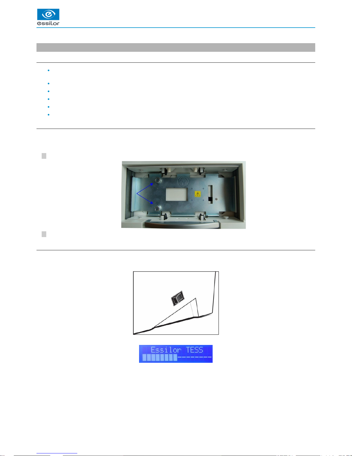
Before any use, it is that you remove the transport stabilizing system.REQUIRED
To do this:
Remove the two screws holding the stabilizing plate.
Remove the stabilizing shim (save these two screws as well as the shim for possible re-use).
c. Turning on and off the product
Turning on the product
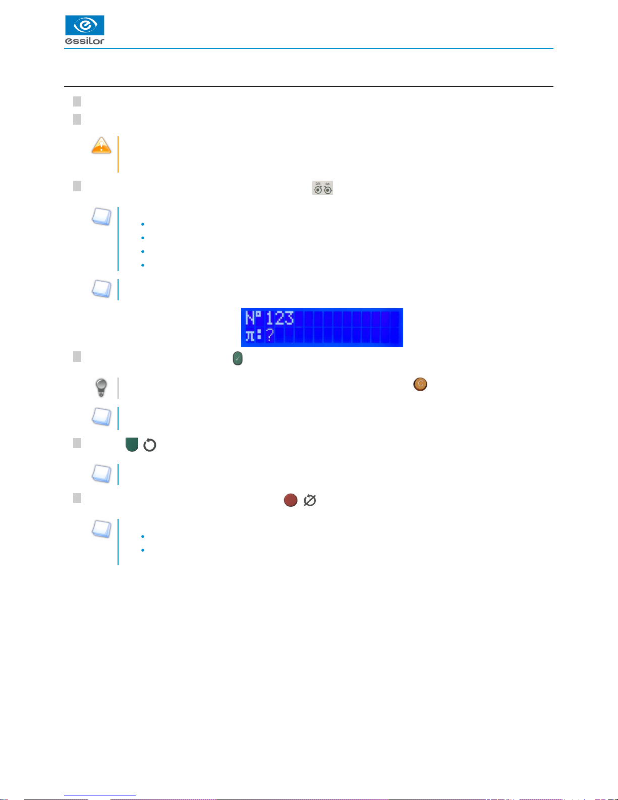
Press on the pushbutton for approximately 1 second, then release:
> The display indicates:
> At the end of powering up, the tracer is working.
Page 17
USER MANUAL > INSTALLATION
TESS > V4 - 01.17 17
2
1
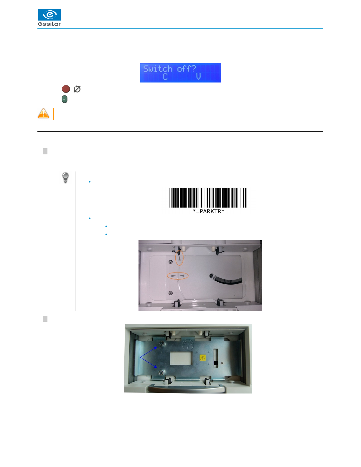
Machine shutdown.
Press on the pushbutton for approximately 1 second, then release:
> The display indicates:
> Press on ( ) to stop the power-down process.
> Press on to confirm the power-down process.
By pressing the pushbutton for too long you will force the device to turn off. This action will cause a warning message to
appear the next time the machine is started.
d. Packing of the device
To pack the tracer:
Turn off the device.
It is also possible to use:
the barcodes below:
it is also possible to put it manually in parking position using marks:
two horizontal arrows for the position rotation: they must be aligned,
a vertical arrow for the output position: this arrow must be aligned with the left stud of the back jaw.
Position the plate and insert the two screws.
The device is put automatically into parking position.>
Page 18
USER MANUAL > INSTALLATION
18 TESS > V4 - 01.17
212
1
1.
2.
3.
4.
5.
6.
1.
2.
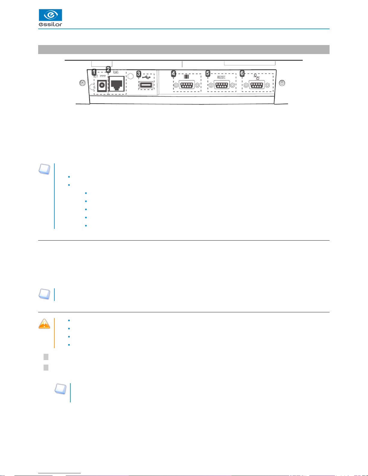
3. Connections
Power socket
Ethernet port
USB port
Barcode tracer port
Serial port
Edger connection port
Depending on your configuration, the tracer can be connected to the RS323 port through:
a computer,
a Essilor edger:
Delta T
Delta 2
Jess
JessIE
JessD
a. Connection to a computer
There are two methods to connect the tracer to a computer:
Connect RS232C cable to the serial port of the tracer (cf image 5, shown above) and on a serial port RS232C of the
computer.
Connect the RJ-45 cable to the Ethernet port of the tracer (cf image 2, shown above) and on your Ethernet network (switch,
router, faceplate…).
Before any Ethernet connection, it is imperative to know the structure of the network to which the tracer will be connected.
b. Connection to an Essilor edger (Delta T, Jess, JessIE, JessD)
The connection of the tracer to the edger will be carried out with the two devices powered off.
The voltage indicated on your devices (tracer, power supply) must correspond to the provided power.
Avoid connectors or adapters which are likely to not ensure good contact.
Check that the cables do not pass near to disruptive electric elements: electric motors, fluorescent tubes, radios, etc.
Check that the device is turned off.
Connect the specific black cable delivered with Delta T: refer to the guidance labels found on the side, and connect the of
edger connection port of the tracer (cf image 6, shown above) with the RS232 port of the edger.
The cable used is a cross cable.
Make sure to comply with the direction of the connection indicated on the labels of the cable in correspondence with
the symbols used on the edger and the tracer.
Page 19
USER MANUAL > INSTALLATION
TESS > V4 - 01.17 19
7
6
5
4
3
2
1
4
3
7
6
5
4
3
2
1
4
3
Connect the line connector cord of the external power supply to the tracer (cf image 6, shown above) and to the outlet, after
you ave made sure that it is grounded.
If necessary check the outlet grounding with your electrician.
Start the tracer.
When using it with:
Delta T: refer to the user manual of the edger to configure the installation suitably.
A login PC and edger, you can combine the two installations described above.
c. Login with a Delta 2 edger
Connect the RJ-45 cable of the tracer to the edger.
Then to the tracer:
Press simultaneously on and “1”.
Press on “6. Communicate” then press on .
In the menu “1. Protocol”:
Click on then on .
Press to confirm.
Press on ( ) to exit the menu.
Click on then on .
Press to confirm.
Press on ( ) to exit the menu.
Click on then on .
Press to confirm.
Press on ( ) to exit the menu.
Then, configure the IP addresses as follows:
Press simultaneously on and “1”.
- Press on “6. Communicate” then press on .
- Press on “2. Parameters” then press on .
- Lastly, press on “3. IP” then press on .
Enter the elements below:
Static mode
IP: 192.168.128.12
Mask: 255.255.255.0
Page 20
USER MANUAL > INSTALLATION
20 TESS > V4 - 01.17
1.
2.
3.
4.
5.
6.
7.
8.
9.
10.
11.
12.
13.
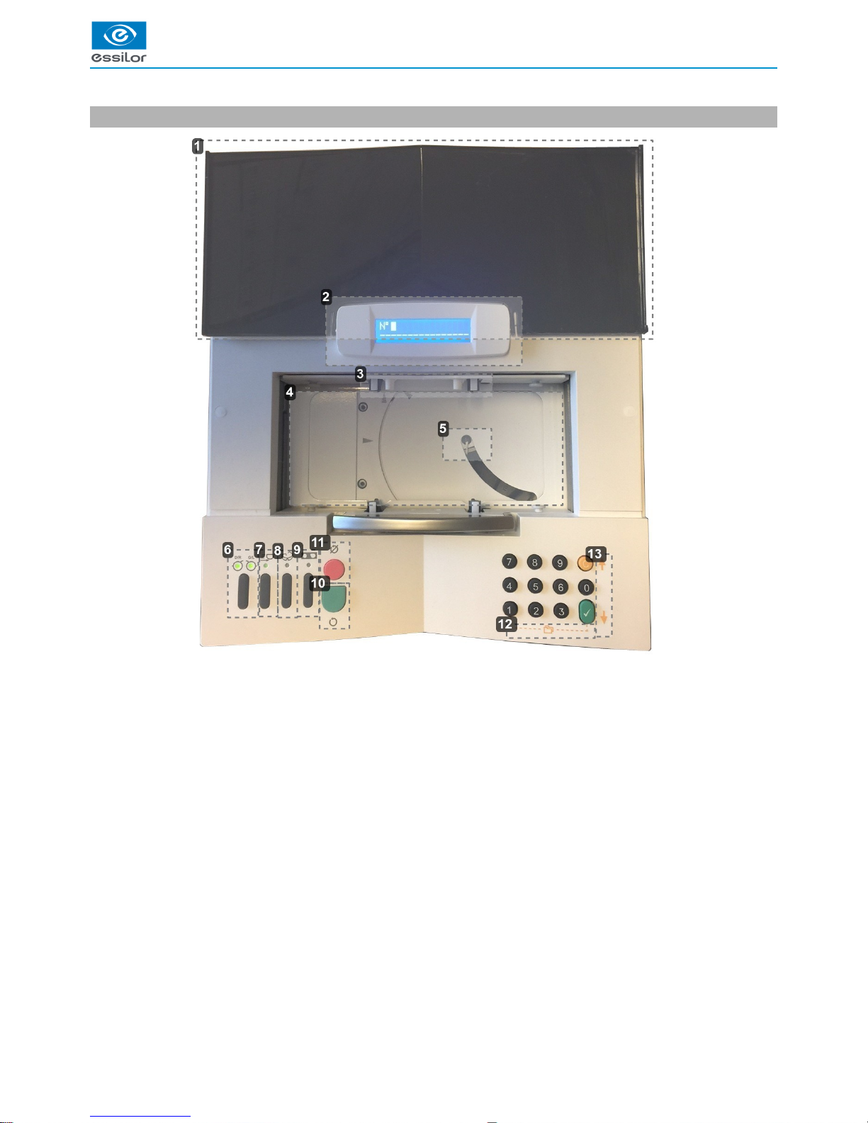
4. Tracer description
Protective cover
Two line display
Tightening clamps
Tracing centering
Feeler
Selection RE, LE, RLE
“Precal lenses” order cycle selection
“Very high-base frame” cycle selection
Calibration test launch
Tracing cycle initialization
Stop of tracing cycle
Access to the internal menu
Navigation arrows
Page 21
USER MANUAL > INSTALLATION
TESS > V4 - 01.17 21
3
2
1
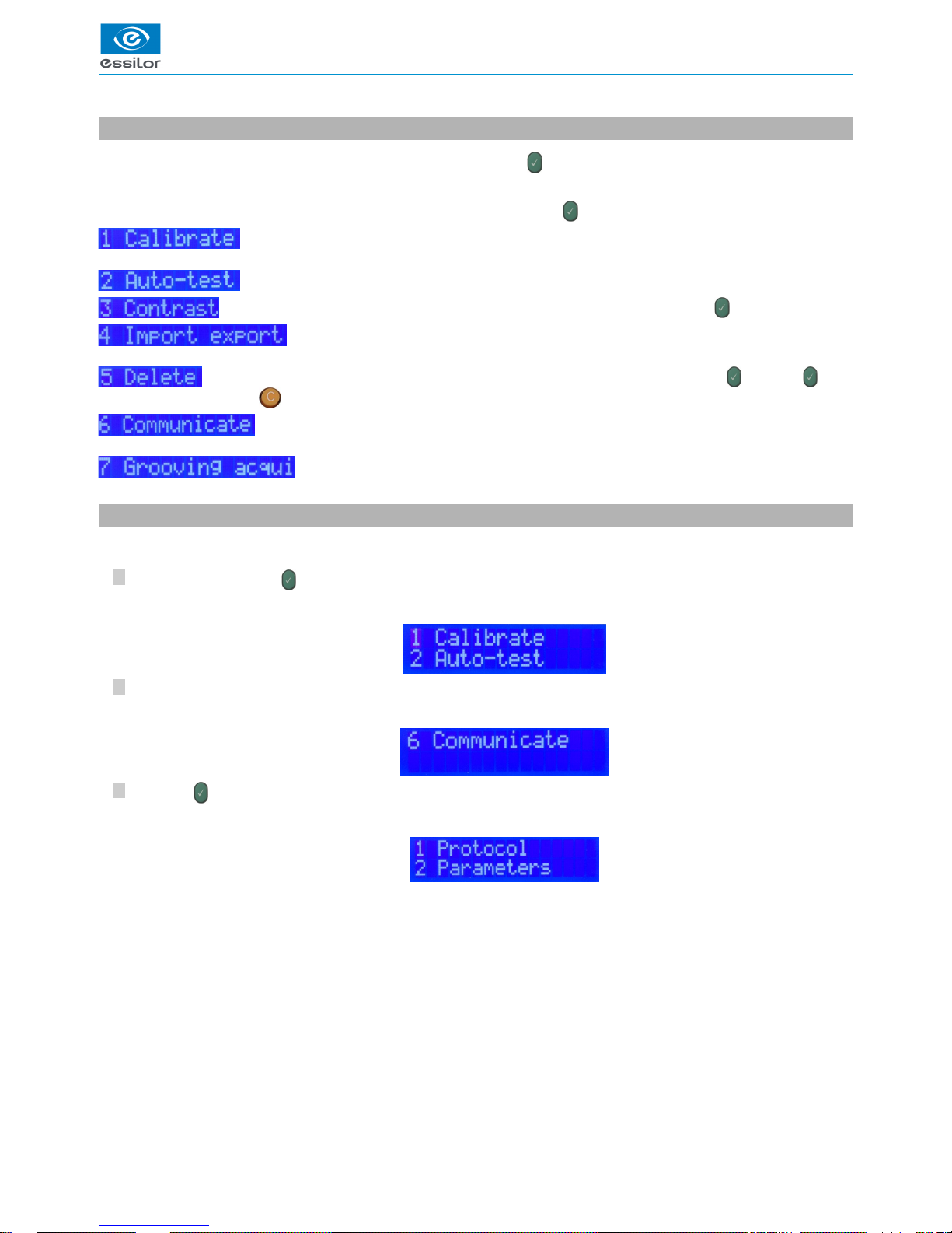
5. Presentation of the internal menu
The internal menu of the tracer is accessible by pressing simultaneously on and “1”.
It is composed of 7 sub-menus.
To access one of these sub-menus, enter the figure corresponding, then press on :
: launching of a complete calibration. For more information, consult the section Auto-Maintenance >
calibration. (p.54)
: launching of an autotest. For more information, consult the section Auto-Maintenance > Autotest. (p.55)
: adjustment of the display contrast; enter the desired value (from 1 to 9), then press on .
: data exchange with an external USB key. For more information, consult the section Import/export.
(p.57)
: deletion of information from the tracer; enter the desired value (from 1 to 9), then press on . Press on again
to confirm the deletion or on to cancel the deletion.
: setting of the communications of the tracer with your environment. For more information, consult the
Installation > Connections. (p.18)
: access the three modes of groove acquisition. For more information, consult the section
Utilization of the tracer > Frame tracing > Groove acquisition. (p.47)
6. Connection configuration
To configure the connection:
Press simultaneously on and “1”.
Press on “6”.
Press on to enter the menu.
The display indicates:>
The display indicates:>
The display indicates:>
Page 22
USER MANUAL > INSTALLATION
22 TESS > V4 - 01.17
5
4
3
2
1
5
4
3
2
1
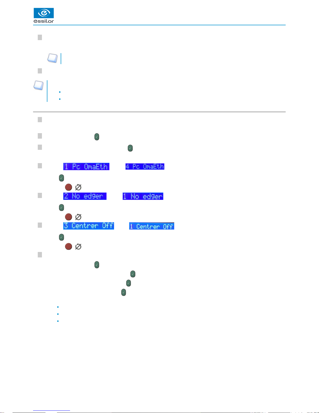
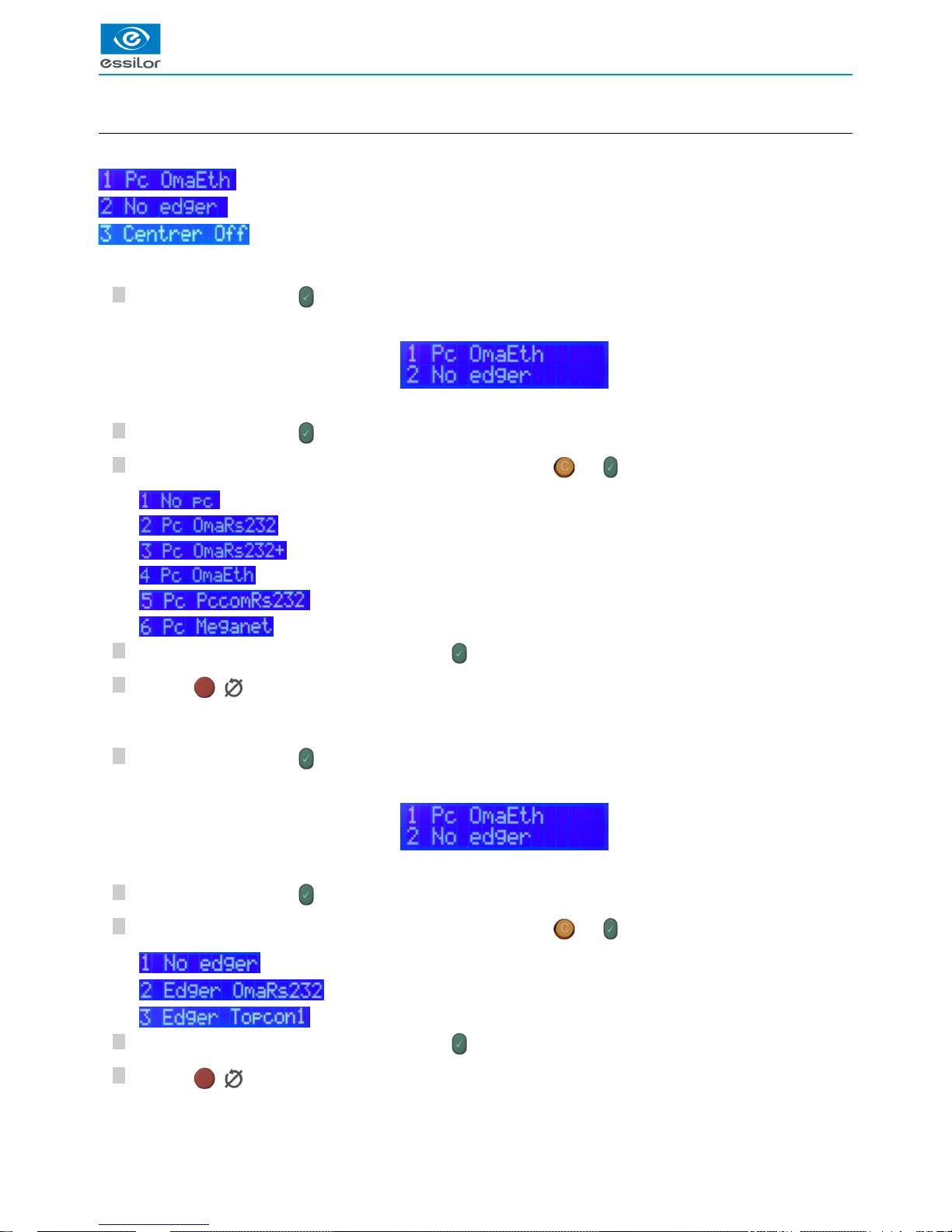
a. Configuration of protocols
The menu “1. Protocol” is composed of 3 sub-menus:
: configuration of PC connection
: configuration of the edger connection
: configuration of the blocker connection
To configure PC connection
Press on “1”, then press on .
Press on “1”, then press on to make your choice.
Then choose the desired protocol by navigating the menu using the keys and .
: no PC connection
: OMA protocol, with RS232 connection
: OMA protocol for Check Pro, with RS232 connection
: OMA protocol, with Ethernet connection
: PCCom protocol for Opsys V1
: specific Japan protocol
Enter the selected line number selected then, press on to confirm.
Press on ( ) to exit the menu.
To configure the edger connection
Press on “1”, then press on .
Press on “2”, then press on to make your choice.
Then choose the desired protocol by navigating the menu using the keys and .
: no edger connection
: edger connection with the provided cord
: specific Topcon edger protocol
Enter the selected line number selected then, press on to confirm.
Press on ( ) to exit the menu.
The display indicates by default:>
If not, it displays the last memorized choice.>
The display indicates by default:>
If not, it displays the last memorized choice.>
Page 23

USER MANUAL > INSTALLATION
TESS > V4 - 01.17 23
5
4
3
2
1
To configure the blocker connection
Press on “1”, then press on .
Press on “3”, then press on to make your choice.
Then choose the desired protocol by navigating the menu using the keys and .
: by default mode
: connection with Iness
Enter the selected line number selected then, press on to confirm.
Press on ( ) to exit the menu.
The display indicates by default:>
If not, it displays the last memorized choice.>
Page 24

USER MANUAL > INSTALLATION
24 TESS > V4 - 01.17
5
4
3
2
1
5
4
3
2
1
5
4
3
2
1
b. Configuration of parameters (optional step)
Press simultaneously on and “1”.
Press on “6”.
Press on to enter the menu.
Press on “2”, the, Press on to access the configuration of default settings:
Serial link
Speed Flow control
INSTRUCTIONS FOR
USE
PC Port 19200 Inspection Opsys configuration
Edger port 19200 Inspection Configuration Delta T
Any modification of this configuration could harm the proper performance of the instruments. We advise that you
modify the configuration of this menu only if your configuration is not compatible with the configuration suggested by
fault and with help from your technician.
Press on “2”, the, press on to configure the data of menu “2: Settings.”
PC Port
Edger port
IP
The display indicates:>
The display indicates:>
The display indicates:>
Three choices are then possible:>
Page 25

USER MANUAL > INSTALLATION
TESS > V4 - 01.17 25
6
5
4
3
2
1
6
5
4
3
2
1
6
5
4
3
2
1
6
5
4
3
2
1
6
5
4
3
2
1
6
5
4
3
2
1
1.
2.
3.
4.
5.
1.
2.
3.
4.
5.
Configure PC port
Press on “1”, then press on .
If the choice on line 1 does not correspond to your configuration, press on “1”, then press on to choose the transmission
speed in bauds:
9600
19200
38400
57600
115200
Choose the desired speed by navigating the menu using the keys and .
Enter the chosen line number selected, then press on to confirm.
Press on ( ) to exit the menu.
If the choice on line 2 does not correspond to your configuration, press on “2”, then press on to choose the flow test:
: no equipment flow test (usual configuration)
: activated equipment flow test
Configure the edger port
Press on “2”, then press on .
If the choice on line 1 does not correspond to your configuration, press on “1”, then press on to choose the transmission
speed in bauds:
9600
19200 (usual speed)
38400
57600
115200
Choose the desired speed by navigating the menu using the keys and .
Enter the chosen line number selected, then press on to confirm.
Press on ( ) to exit the menu.
If the choice on line 2 does not correspond to your configuration, press on “2”, then press on to choose the flow test:
The display indicates by default:>
If not, it displays the last memorized choice.>
The display indicates by default:>
If not, it displays the last memorized choice.>
Page 26

USER MANUAL > INSTALLATION
26 TESS > V4 - 01.17
4
3
2
1
4
3
2
1
3
2
1
8
7
4
3
2
1
4
3
2
1
3
2
1
8
7
4
3
2
1
4
3
2
1
3
2
1
8
7
1.
2.
3.
: activated equipment flow test
: no equipment flow test (usual configuration)
Enter the chosen line number selected, then press on to confirm.
Press on ( ) to exit the menu.
Configure the IP
To configure the IP:
Press on “3”, then press on .
> It is then possible to configure:
The IP mode
The IP address:
The subnet mask
IP mode
If the choice indicated does not correspond to your configuration, press on “1”, then press on :
: dynamic IP addressing via DHCP-server
: menu not used
: static IP addressing
Enter the chosen line number selected, then press on .
Press on ( ) to exit the menu.
IP address
If the address indicated does not correspond to your configuration, press on “2”, then press on :
Press on to confirm the address or on to cancel the change.
Enter the new address, then press on to confirm.
To enter the 192.168.0.12 IP address manually: type the 12 figures: 1 9 2 1 6 8 0 0 0 0 1 2 (without spaces).
The tracer will automatically add the “.”.
Press on ( ) to exit the menu.
Subnet mask
If the address indicated does not correspond to your configuration, press on “3”, then press on :
Press on to confirm the address or on to cancel the change.
Enter the new mask then, press on to confirm.
Press on ( ) to exit the menu.
Page 27

IV. CHECK PRO
Page 28

USER MANUAL > CHECK PRO
28 TESS > V4 - 01.17
Page 29

USER MANUAL > CHECK PRO
TESS > V4 - 01.17 29
The Check Pro software allows you to:
Know the statistics of tracings.
Understand the error messages generated by the tracer.
Perform an autotest from the computer.
Perform a calibration inspection from a computer.
Perform calibrations from a computer.
Personalize the display of the tracer (function not currently available).
Check Pro is compatible with following the operating systems:
Windows 98
Windows 2000
Windows XP
Windows Vista
Windows 7 (32 and 64 bits)
Windows 8 and 8.1
Windows 10
Page 30

USER MANUAL > CHECK PRO
30 TESS > V4 - 01.17
4
3
2
1
4
3
2
1
1. Installation
Insert the CD-Rom delivered with the tracer.
Click on “ “then on “ ".checkPro OK
Click on “ “and follow the various steps of installation.Next
Click on “ ".Finish
The following window is displayed:>
The installation starts.>
The following window is displayed:>
At the end of the process, the following window is displayed:>
The application is automatically launched.>
Page 31

USER MANUAL > CHECK PRO
TESS > V4 - 01.17 31
21212
1
2. Instructions for use
Click on the desktop icon and select the desired language.
Configure the desired properties and click on “ ".OK
From this screen, all the functions are accessible through the various icons.
The following window is displayed:>
Page 32

USER MANUAL > CHECK PRO
32 TESS > V4 - 01.17
3
2
1
3
2
1
3
2
1
3
2
1
3
2
1
3
2
1
3
2
1
3
2
1
3
2
1
a. PC Configuration
Click on .
Choose the desired language of operation.
To configure the login between the tracer and the computer click on “ ".Port:
On the left side of the window you can activate the communication via serial port (remember to configure the tracer in
the same way by using Oma + PC protocol).
On the right side of the window the list of the machines detected in IP are available.
The following window is displayed:>
Page 33

USER MANUAL > CHECK PRO
TESS > V4 - 01.17 33
2
1
444
2
1
444
2
1
444
1.
2.
3.
4.
5.
6.
7.
8.
9.
10.
11.
Then, click on “ ".OK
b. Statistics
Click on .
Total number of cycles
Number of symmetrical binocular cycles
Number of asymmetrical binocular cycles
Number of RE monocular cycles
Number of LE monocular cycles
Number of very high-base cycles
Number of pattern cycles
Number of calibrations
Number of calibration inspections
Number of high-precision (metal) tracings
Number of precal cycles
Click on to return to the previous screen.
The previous screen is displayed.>
The following window is displayed:>
Page 34

USER MANUAL > CHECK PRO
34 TESS > V4 - 01.17
21212121212
1
1.
2.
c. Error message
Click on .
List of recorded “technician” errors
List of recorded “optician” errors.
Click on to return to the previous screen.
The following window is displayed:>
Page 35

USER MANUAL > CHECK PRO
TESS > V4 - 01.17 35
4
3
2
1
4
3
2
1
4
3
2
1
4
3
2
1
4
3
2
1
4
3
2
1
1.
2.
3.
d. About the tracer...
Connect the tracer to the computer according to the selected login mode.
Display on the main screen the list of tracer choices then, choose the port which the tracer is connected to, COM3 for
example.
Click on .
Tess serial number
Tess memory version
Check Pro memory version
Information is displayed after a few seconds.
Click on to return to the previous screen.
The following window is displayed:>
Page 36
USER MANUAL > CHECK PRO
36 TESS > V4 - 01.17
6
5
4
3
2
1
6
5
4
3
2
1
6
5
4
3
2
1
6
5
4
3
2
1
6
5
4
3
2
1
6
5
4
3
2
1
6
5
4
3
2
1
6
5
4
3
2
1
6
5
4
3
2
1
1.
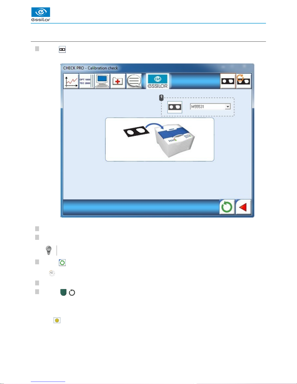
e. Calibration test
Click on .
Number of the frame gauge caliber
Choose the number of the frame gauge caliber.
Position stably the frame gauge within the tracing boundary on the 4 lower studs.
The “V” must be open aiming up.
Click on to validate.
Check the sizing number on the display of the tracer.
Press on ( ) of the tracer to launch tracing.
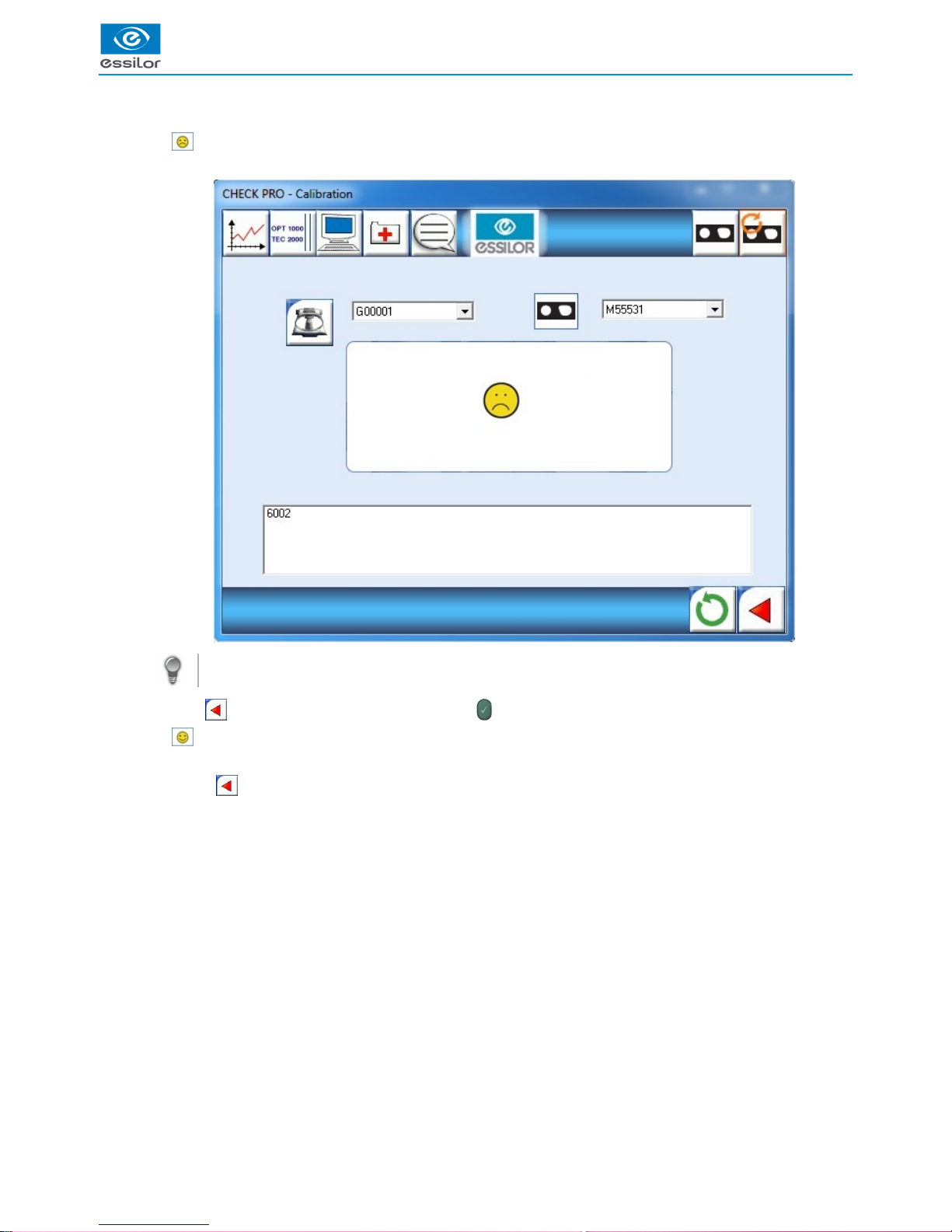
1. Test NOK.
> The code error is displayed in the Check Pro window.
The following window is displayed:>
is displayed on the Check Pro window.
>
The inspection starts.>
At the end of the inspection, there are two possible cases:>
Page 37

USER MANUAL > CHECK PRO
TESS > V4 - 01.17 37
> In this case, carry out another inspection. If the result is again KO, perform a calibration.
For more information, consult the section error codes & barcodes > error codes. (p.65)
Click on to return to the previous screen, then press to confirm the tracer code.
2. Test OK.
> You can use of the tracer again, your tracer’s display is waiting for the job.
> Click on to return to the previous screen.
Page 38

USER MANUAL > CHECK PRO
38 TESS > V4 - 01.17
8
7
6
5
4
3
2
1
8
7
6
5
4
3
2
1
8
7
6
5
4
3
2
1
8
7
6
5
4
3
2
1
8
7
6
5
4
3
2
1
8
7
6
5
4
3
2
1
8
7
6
5
4
3
2
1
8
7
6
5
4
3
2
1
8
7
6
5
4
3
2
1
1.
2.
f. Calibration
Click on .
Number of the pattern gauge caliber
Number of the frame gauge caliber
Choose the frame and pattern gauge caliber numbers corresponding with the gauge caliber used.
Position stably the frame gauge within the tracing boundary on the 4 lower studs.
The “V” must be open aiming up.
Click on to validate.
Check the sizing number on the display of the tracer.
Press on ( ) of the tracer to launch tracing.
Remove the frame gauge and insert the pattern gauge.
Press on ( ) of the tracer.
The following window is displayed:>
is displayed on the Check Pro window.
>
Tracing starts.>
At the end of tracing, the pattern gauge caliber number is displayed on the tracer.>
The second part of the calibration starts.>
Page 39
USER MANUAL > CHECK PRO
TESS > V4 - 01.17 39
1. Calibration NOK.
> The code error is displayed in the Check Pro window.
For more information, consult the section error codes & barcodes > error codes. (p.65)
Click on to return to the previous screen, then press to confirm the tracer code.
2. Calibration OK.
> You can use of the tracer again, your tracer’s display is waiting for the job.
> Click on to return to the previous screen.
At the end of calibration, calculation begins and lasts approximately 10 min. Two cases possible:>
Page 40

USER MANUAL > CHECK PRO
40 TESS > V4 - 01.17
Page 41

V. USE OF THE TRACER
Page 42

USER MANUAL > USE OF THE TRACER
42 TESS > V4 - 01.17
Page 43

USER MANUAL > USE OF THE TRACER
TESS > V4 - 01.17 43
2
1
1
3
2
1
1
1. Initialization
Power up the tracer.
2. Tracing
If you wish to assign a job number
Enter the desired job number, between 1 and 200 (beyond your job will not be memorized).
Press to confirm.
Press on ( ) of the tracer to launch tracing.
If you wish to work on the current job
Press on ( ) of the tracer to launch tracing.
Working on the current job allows for a simplified identification of the job between the tracer and the edger.
In this case, the jobs are not memorized.
If you work with barcodes
Scan the barcodes.
Press on ( ) of the tracer to launch tracing.
The display indicates:>
A beep indicates that the initialization phase is successful.
RE and LE LEDs light up on the tracer.
>
The tracer systematically requests if you want to add a job number.>
The job number is displayed.>
The number is displayed on the screen.>
Page 44

USER MANUAL > USE OF THE TRACER
44 TESS > V4 - 01.17
3. Frame tracing
Page 45
USER MANUAL > USE OF THE TRACER
TESS > V4 - 01.17 45
6
5
4
3
2
1
6
5
4
3
2
1
6
5
4
3
2
1
6
5
4
3
2
1
6
5
4
3
2
1
6
5
4
3
2
1
6
5
4
3
2
1
6
5
4
3
2
1
6
5
4
3
2
1
a. Standard tracing
Remove the lenses from the frame.
Insert the frame onto the tracing table while making sure that each circle rests between the tightening clamps.
Repair the frame if necessary.
Make sure the hinge is closed correctly.
Take care not to crush the frame if it is flexible.
Select your choice of tracing side by pressing repeatedly on .
While carrying out:
1 support: asymmetric binocular tracing, the two diodes are lit (selected item by default),
2 supports: monocular tracing of the right eye, diode D/R is lit,
3 supports: monocular tracing of the left eye, diode G/L is lit,
4 supports: symmetrical binocular tracing, the two diodes flicker.
In the case of a monocular tracing, you will be asked to enter the value of the bridge at the end of the tracing using the
numeric keypad.
Enter the desired value, then press on .
As long as the entered value is not confirmed, you can correct it by pressing on .
No other action is possible without this entry.
The available frame dimensions can then be displayed.
Press on ( ) of the tracer to launch tracing.
During the use of the tracer with a Delta T edger or a Jess, JessIE, JessD edger please wait for the end of acquisition
to call up the shape on the edger.FRONT
If you wish to stop the cycle during tracing, press on ( ):
While carrying out:
1 support: the cycle of tracing is stopped (gathered data is lost),
2 supports: rebooting of the cycle and sounding of the audible signal. After a few seconds the tracer is again
ready to read.
Page 46
USER MANUAL > USE OF THE TRACER
46 TESS > V4 - 01.17
4
3
2
1
4
3
2
1
4
3
2
1
b. Groove detection
By default, feeler insertion is configured in the centre of the frame thickness: .
Enter the desired job number, between 1 and 200 (beyond your job will not be memorized).
Press to confirm.
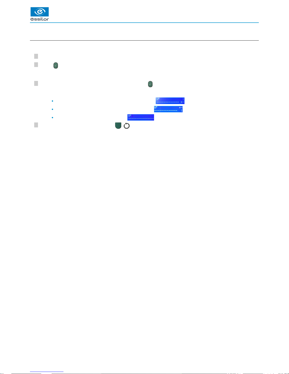
After the validation of the job number or current job, press on to choose the adapted feeler insertion.
While carrying out:
1 support, choose low insertion: arrow aiming downwards .
2 supports, choose high insertion: arrow aiming upwards .
3 supports, you return to the main screen .
Once the insertion is configured, press on ( ) of the tracer to launch tracing.
The job number is displayed.>
Page 47
USER MANUAL > USE OF THE TRACER
TESS > V4 - 01.17 47
3
2
1
3
2
1
3
2
1
3
2
1
3
2
1
3
2
1
3
2
1
3
2
1
3
2
1
c. Groove acquisition settings
Press simultaneously on and “1”.
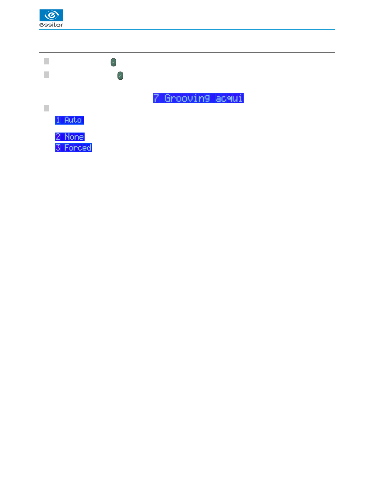
Press on “7”, then press on to access the “Grooving acquisition” menu.
Choose among the 3 modes of groove acquisition:
: if the thickness of the frame is less than 3.5 mm, the frame is detected as metal. Groove acquisition is then
automatically triggered.
: Groove detection is never performed.
: Groove detection is performed in every case.
The display indicates:>
Page 48
USER MANUAL > USE OF THE TRACER
48 TESS > V4 - 01.17
2
1
7
6
5
4
3
2
1
2
1
7
6
5
4
3
2
1
2
1
7
6
5
4
3
2
1
d. Special cycles
Precal tracing,
Press .
When this function is selected, tracing is performed in RE monocular by default, with a very fast cycle of tracing, intended for the
ordering of pre-gauged lenses (optional option).
You can choose the left eye by pressing on the selection button on the tracing side (binocular tracing is impossible).
Tracing is carried out on a standard cycle.
“Very high-base” frame tracing
Press .
The tracer can read high bases on a standard cycle. This specific cycle allows for the reading of very high-base frames for which
binocular tracing can be done only monocular purposes.
Activate this function when you want to read a very high-base frame.
Choose the tracing side, right or left.
Position the eye as flat as possible to place the frame in the tracing table.
The black clamps which hold the eye to be read must be located in the middle of the circle.
Gently close the jaw to hold the frame.
Press on ( ) of the tracer to launch tracing.
Enter the value of the bridge, then press on .
Position the frame in order to read the opposite eye.
Launch a new tracing.
“Very small B-dimension” tracing
This kind of tracing is appropriate for frames having a B-dimension ≤ 19mm.
Position the accessory as indicated below:
Perform your tracing.
Page 49

USER MANUAL > USE OF THE TRACER
TESS > V4 - 01.17 49
2
1
5
4
3
2
1
3
2
1
2
1
5
4
3
2
1
3
2
1
2
1
5
4
3
2
1
3
2
1
For more information, consult the Utilization of the tracer > performing a tracing. (p.43)
e. Patter Tracing , demo lens or recut lens, pattern holder
To fix a demo lens or recut lens to the pattern holder:
Block the lens in the boxing center, making sure it is properly centered.
Insert the blocked lens and hold it in position with your index finger
Press on the knurled button, screwing, until the blocked lens is immobilized.
The feeling pressure on the lens being weak, it is pointless to excessively screw down the knurled button.
Screwing in the knurled knob inside the posiblock does not have a functional impact on the posiblock.
To fix the pattern on the pattern holder:
Unscrew the holding screw on the pattern holder tip.
Fix the pattern on the tip of the pattern holder:
nose to the right for a right lens, and to the left for a left lens
tip positioner of the pattern holder towards the bottom of the pattern.
Insert the block pattern and hold it in position with your index finger (like fixing a lens).
Align the marking (right nose) or (left nose) of the pattern holder with that of the pattern:
Press on the knurled knob, screwing it, until the pattern is immobilized (as for fixing a lens).
The feeling pressure on the lens being weak, it is pointless to excessively screw down the knurled button.
The screwing of the knurled knob inside the posiblock of the nozzle has no functional impact on the latter.
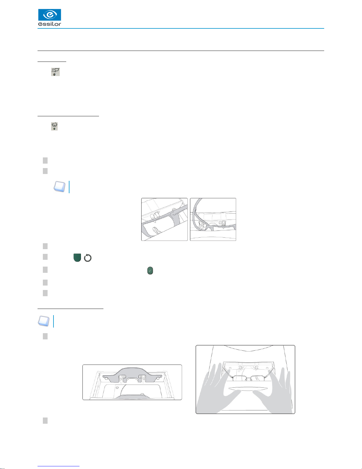
Position the pattern holder in the tracing table:
Position the pattern holder in place in the tracing table.
Fit the front tab of the pattern holder between the cylindrical white pins on the tracing table (in front of you).
You can place the pattern holder in the tracing table.>
Page 50

USER MANUAL > USE OF THE TRACER
50 TESS > V4 - 01.17
333
Adjust the jaws of the tracing table so as to block the pattern holder.
Press on ( ) of the tracer to launch tracing.
The tracer automatically detects that it is a tracing pattern, it asks you to select the tracing eye.>
At the end of tracing, enter the value of the nose using the numeric keypad, then press on .
>
Page 51

VI. AUTO-MAINTENANCE
Page 52

USER MANUAL > AUTO-MAINTENANCE
52 TESS > V4 - 01.17
Page 53

USER MANUAL > AUTO-MAINTENANCE
TESS > V4 - 01.17 53
4
3
2
1
The functions described in this menu will allow you to correct issues yourself, or to direct the technician in solving any problems you
might encounter while using the tracer.
1. Calibration test
To ensure “high precision” performance is maintained, please carry out a calibration inspection regularly.
Press on to select the “calibration test” function.
Select the gauge caliber number on the tracer then, press on .
Position stably the frame gauge within the tracing boundary on the 4 lower studs.
The “V” must be open aiming up.
Press on ( ) of the tracer to launch tracing.
1. Test OK.
> The display indicates:
Press on and continue to use the tracer.
2. Test KO.
> The display indicates:
Press on and perform a complete calibration.
At the end of tracing, the clamps open, an audible signal indicates the end of calculations. Two possible cases:>
Page 54

USER MANUAL > AUTO-MAINTENANCE
54 TESS > V4 - 01.17
9
8
7
6
5
4
3
2
1
2. Calibration
This step requires a certain amount of time and blocks the use of the tracer. It is however essential for the maintenance of
the tracer’s performance.
Press simultaneously on and “1”.
Select by pressing on “1” then on .
The first step consists in calibrating the “pattern” precision using the metal pattern gauge.
With:
G: pattern
00001: Pattern number provided by default with the tracer.
Select the pattern number delivered with the tracer then, press on to launch the calibration or to exit the menu.
Position the pattern provided with the tracer on the pattern holder (nose towards the left).
Make sure that it is stable.
Then, position the pattern holder within the tracing boundary.
For more information, consult the section Tracer Utilization > frame tracing > pattern tracing, demo or recut lens,
pattern holder. (p.49)
Press on ( ) of the tracer to launch tracing.
Select the gauge caliber number on the tracer then, press on .
Make sure that the pattern holder number and the gauge caliber number are identical.
Position stably the frame gauge within the tracing boundary on the 4 lower studs.
The “V” must be open aiming up.
Press on ( ) of the tracer to launch tracing.
During the calculation phase, the display indicates:
This operation can take about ten minutes.
The display indicates:>
At the end of tracing, the display indicates:>
Page 55
USER MANUAL > AUTO-MAINTENANCE
TESS > V4 - 01.17 55
3
2
1
1. Calibration OK.
> The display indicates “OK”:
Press on and continue to use the tracer.
2. Calibration KO.
> The display indicates a code error: in this case, start again calibration.
If the problem persists, contact a technician.
For more information, consult the section error codes & barcodes > error codes. (p.65)
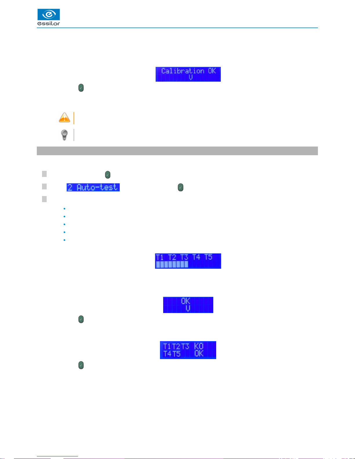
3. Autotest:
This function allows you to test the various movements of the tracer.
Press simultaneously on and “1”.
Select by pressing on “2” then on .
The tests starts:
T1: Jaws
T2: Feeler reproducer
T3: Rotation
T4: Feeler transfer
T5: Carriage transfer
1. Tests OK.
> The display indicates:
Press on and continue to use the tracer.
2. If one or more tests KO.
> The display indicates the result of each test:
Press on and contact your technician.
At the end of tracing, the clamps open, an audible signal indicates the end of calculations. Two possible cases:
>
The display indicates:>
At the end of the tests, an audible signal indicates the end of the process. Two possible cases:>
Page 56

USER MANUAL > AUTO-MAINTENANCE
56 TESS > V4 - 01.17
Page 57

VII. IMPORT/EXPORT
Page 58

USER MANUAL > IMPORT/EXPORT
58 TESS > V4 - 01.17
Page 59
USER MANUAL > IMPORT/EXPORT
TESS > V4 - 01.17 59
3
2
1
5
4
3
2
1
Thanks to its USB connector, the tracer can quickly exchange information remotely with your technician.
To achieve this, an USB key compatible with the tracer is available at your dealer.
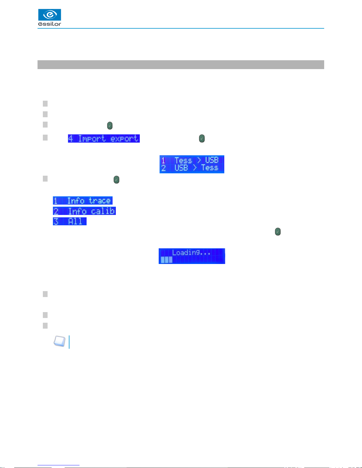
1. Export
This function allows you to transmit internal information to the tracer and/or to your technician in order to optimize the analysis of a
possible malfunction.
From the tracer
Power up the tracer.
After the initialization phase, insert the Essilor USB key in the external USB port of the tracer.
Press simultaneously on and “1”.
Select by pressing on “4” then on .
Press on “1”, then press on to transfer the information from the tracer to the USB key.
Three possible choices:
: transfer of the data related to tracer piloting.
: transfer of the data related to calibrations.
: transfer of all the data.
From the computer
Insert the Essilor USB key into the computer.
Double-click on the device.
Copy-paste the desired files into a specific space and transmit them to your technician.
It might be necessary to compress the data.
For that you can easily use the tools for compression provided on your computer, WinZip for example.
The display indicates:>
Depending on the files requested by your technician, choose the desired line number, then press on .
>
The display indicates:>
When the export is finished, the tracer is in queued job position, the information having been copied on the USB key.>
The key appears in the list of devices on your computer.>
Page 60
USER MANUAL > IMPORT/EXPORT
60 TESS > V4 - 01.17
6
5
4
3
2
1
4
3
2
1
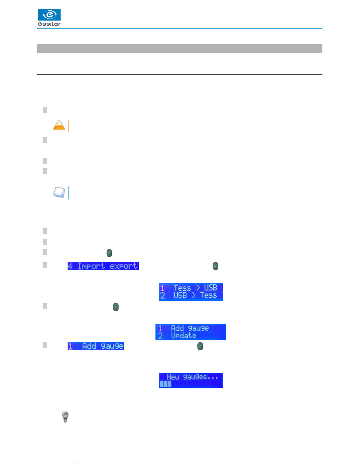
2. Import
This function allows for the upgrade of the product, or the addition of necessary information to the performances of the tracer.
a. Addition of a gauge
This function allows you to record on the tracer the information relative to a gauge frame used for calibration and the calibration
inspection.
From the computer
Insert the Check CD-ROM (CD no. 2) delivered with the gauge which you wish to put into the tracer.
The number indicated on the gauge must be identical to the number indicated on CD.
Insert the Essilor USB key in the computer's USB port.
Double-click on the device.
Copy the files of the type “M66173OD.TXT” and “M66173OG.TXT” found on the root of the CD-ROM and copy them to the
root of the USB key.
The name of the files corresponds to the numbers of the gauges.
From the tracer
Power up the tracer.
After the initialization phase, insert the Essilor USB key in the external USB port of the tracer.
Press simultaneously on and “1”.
Select by pressing on “4”, then press on .
Press on “2”, then press on to transfer the information from the USB key to the tracer.
Select by pressing on “1”, then press on .
For more information, consult the section error codes & barcodes > error codes. (p.65)
The key appears in the list of devices on your computer.>
Once the files are copied, remove the USB key.>
The display indicates:>
The display indicates:>
The importing is automatically launched.>
The display indicates:>
When the importing is finished, the tracer is put in queued job position.
The new gauge is available.
>
Page 61

USER MANUAL > IMPORT/EXPORT
TESS > V4 - 01.17 61
8
7
6
5
4
3
2
1
3
2
1
7
Remove the USB key.
b. Software update
From the computer
Insert the Essilor USB key into the computer's USB port.
Double-click on the device.
Copy the file into format” “, which was already sent to you on the root of the USB key..tar .gz
From the tracer
Power up the tracer.
After the initialization phase, insert the Essilor USB key in the external USB port of the tracer.
Press simultaneously on and “1”.
Select by pressing on “4”, then press on .
Press on “2”, then press on to transfer the information from the USB key to the tracer.
Select by pressing on “2”, then press on .
Press on to confirm or on to cancel.
Remove the USB key, then press on .
For more information, consult the section error codes & barcodes > error codes. (p.65)
The key appears in the list of devices on your computer.>
Once the file is copied, remove the USB key.>
The display indicates:>
The display indicates:>
The display indicates:>
The display indicates:>
At the end of the update, the display indicates:>
The tracer turns off then restarts at the end of approximately 5 seconds.>
The tracer is put in queued job position.>
Page 62

USER MANUAL > IMPORT/EXPORT
62 TESS > V4 - 01.17
Page 63

VIII. ERROR CODES & BARCODES
Page 64

USER MANUAL > ERROR CODES & BARCODES
64 TESS > V4 - 01.17
Page 65

USER MANUAL > ERROR CODES & BARCODES
TESS > V4 - 01.17 65
1. Error codes
You will find below the actions to be carried out if an error code appears.
If one of these codes appears repeatedly or persists after employing the solution proposed below, note the code and contact your
technician.
Code Meaning
Opt1 Contact your technician with the data from the machine
Opt1000 Software update failure > Restart the device. It will restart automatically on the previous model
Opt4000
Software error (in the tracing processing task) > Restart the device
If the error reoccurs several times, contact your technician
Opt4001
Software error (in the tracing cycle task) > Restart the device
If the error reoccurs several times, contact your technician
Opt4002
Software error (in the PccomV2 communication task) > Restart the device
If the error reoccurs several times, contact your technician
Opt4003
Software error (in the keyboard task) > Restart the device
If the error reoccurs several times, contact your technician
Opt4004
Software error (in the HMI supervisor task) > Restart the device
If the error reoccurs several times, contact your technician
Opt4005
Software error (in the LCD screen management task) > Restart the device
If the error reoccurs several times, contact your technician
Opt4006
Software error at the start-up > Restart the device
If the error reoccurs several times, contact your technician
Opt4007
Software error (in the task supervisor) > Restart the device
If the error reoccurs several times, contact your technician
Opt6000 CDL function not implemented. Perform another action
Opt6001 SUP function not implemented. Perform another action
Opt6002 Insert a pattern or a frame
Opt6003 Check the insertion of the feeler
Opt6004
Groove exhaust
Try a second tracing (in monocular if the frame is heavily cambered)
If the error reoccurs several times, contact your technician
Opt6005 Calibration function not available in table bank-test startup mode
Opt6006 Incorrect “function” barcodes
Opt6007 Barcode numbers too long
Opt6008 Barcode numbers too long
Opt6010 Insert gauge files
Opt6011 Insert the missing gauge
Opt6012 Incorrect tracing table calibration file
Opt6014 Calibrate the tracer
Opt6017 Bad format of the gauge files
Opt6018 Delete jobs
Opt6019 Error related to the contents of OMA job > Restart the device
Opt6021 The statistics file on the errors is erroneous
Opt6022 Barcodes unauthorized with this start-up mode
Opt6023 Restart. The instrument will restart automatically on the old version
Opt6024 External USB key is absent
Opt6025 External USB key was removed
Opt6026 The new software version is incorrect
Opt6027 The gauge pattern is badly positioned
Page 66

USER MANUAL > ERROR CODES & BARCODES
66 TESS > V4 - 01.17
3
2
1
Opt6028 Communication time-out. Check the connection with the computer
Opt6029 The job does not exist
Opt6030 The edging chain does not allow the machining of lenses with a weak B-dimension
Opt6031 The edging chain does not allow the machining of large base lenses
Opt6032 Incorrect gauge frame or major mechanical gap or problem during the digitization
Opt6033 An object blocks the movements of the tracing table
Opt6034 The job does not exist
Opt6035 The gauge in the tracing table is not the correct one. Insert the gauge pattern
Opt6036
The gauge is absent or the gauge in the tracing table is not the correct one. Insert the gauge
frame
Opt6037 Impossible to start > an external USB key is present. Remove this key then restart the product
2. Barcodes
To upgrade the language of the tracer:
Plug in a barcode reader into the tracer external plug.
Turn your tracer on.
From the tracing screen, scan the barcodes of the desired language:
French language option
English language option
Spanish language option
German language option
Portuguese language option
Italian language option
The language of the tracer changes.>
Page 67

USER MANUAL > ERROR CODES & BARCODES
TESS > V4 - 01.17 67
Page 68

Essilor Instruments USA
8600 W. Catalpa Avenue, Suite 703
Chicago, IL 60656
Phone: 855.393.4647
Email: info@essilorinstrumentsusa.com
www.essilorinstrumentsusa.com
 Loading...