

Page 1
User Manual
Page 2

Page 3

CONTENTS
INTRODUCTION 7
I. FIRST STEPS WITH PRO-E 9
1. Descriptive diagrams 11
2. Using the edger 13
a. Turning on the edger 13
b. Switching off the edger 13
c. Using the touch screen and keypads 14
d. Edging screen 15
II. EDGING A LENS 17
1. Edger working environment 19
a. Menu screen 20
b. Calling up a shape 22
c. Lens set-up and feeling 22
2. Perform a Beveling 24
a. Automatic beveling 25
b. Legend screen for customized bevels 26
c. Customized beveling 27
d. Modifying the bevel curve 29
e. Modifying the bevel curve at a particular point 30
f. Displacing the bevel curve 31
3. Perform a high-base bevel 32
a. Captioned screens 33
b. High-base beveling 34
4. Perform a Step bevel 40
a. Captioned screens 41
b. Perform a Step bevel 42
5. Grooving 49
a. Automatic grooving 50
b. Customized groove legend screen 51
c. Customised grooving 52
d. Modifying the groove curve 54
e. Modifying a point in the groove curve 55
f. Displacement of the groove curve 56
6. Produce a Flat-edge finish 56
7. Do a mixed job 57
a. Legend screens 58
b. Configuring the mixed finish 60
8. Perform a Drilled job 62
a. Automatic drilling 63
b. Legend screen for customized drilling 64
c. Customized drilling 65
9. Perform a Polishing 67
10. Chamfering 67
11. Perform a Retouching 68
USER MANUAL> CONTENTS
Page 4

12. Perform a “Super Chamfer” (Pro-E 700) 70
13. Perform a Chemistrie TM job (Pro-E 700) 72
a. Prerequisites 72
b. Preparing a Chemistrie TM job 73
c. Prepare the Chemistrie TM lenses 77
d. Cut a Chemistrie lens 78
14. Carry out a Half Jacket job (Pro-E 700) 81
a. Outline the step bevel trajectory on a Half Jacket shape 81
b. Finalize the step bevel settings in “front surface follow-up” mode 94
c. Modify the shape on Essibox 96
15. M’EYE Sign feature (Pro-E 700) 100
a. To prepare the engraving 100
b. Performing engraving 112
c. Setting up the favorites 116
16. M’EYE Touch feature (Pro-E 700) 117
a. On Essibox 118
b. On the edger 125
III. PREPARING A DRILLED JOB 127
1. Menu screen 129
2. Configuring a drilling point 130
a. Creating a drilling point 131
b. Dimensioning a drilling point 131
c. Adjusting the position of a drilling point 132
IV. CONFIGURING THE EDGER 137
1. Configure the edger 139
a. Time, date and language 139
b. Connections 140
c. Screensaver 141
2. Adjusting the precision of the edger 141
a. Adjusting the diameter of the finished lenses 141
b. Adjusting the position of the bevel and groove 142
c. Adjusting the diameter of drill-holes 143
d. Adjusting the chamfer 144
e. Adjusting the groove 145
f. To adjust the engraving 146
g. Adjust the position of high-base bevel 147
h. Adjust the position of the step bevel 149
3. Restore the factory settings 150
V. MAINTENANCE & SERVICING 151
1. Carrying out the autotests 153
2. Calibrating the touch screen 154
3. Consulting the preventive maintenance screen of the “small tools” module 155
4. Changing or cleaning the edger tools 158
a. Changing or cleaning the drill bit 159
b. Changing or cleaning the mill bit 162
c. Changing the chamfering wheel 165
d. Install and change the step bevel ++ tool 168
e. Installing and changing the engraving tip 171
USER MANUAL> CONTENTS
Page 5

5. Statistics and technical log 174
a. Edger cycles 174
b. Technical log and errors 175
6. Maintaining and cleaning the edger 176
a. Precautions required 176
b. Clean the door, the “small tools” module and the wheels 176
c. Dress the wheels 178
TECHNICAL DATA 181
1. Edger 183
2. Environment 185
GENERAL INFORMATION 187
1. Symbols 189
2. Modifications 189
3. Declaration of conformity 190
4. Copyright 190
5. Materials and products 190
6. Safety instructions: 190
7. Electromagnetic waves 191
8. License agreement for M’EYE Sign™ (Engraving) software 191
a. General information 191
b. Accepted use of the Software and restrictions 192
c. Liability 192
d. Disclaimer of warranties 192
e. Limited liability 192
f. Termination 192
g. Applicable law 193
h. Entirety of the agreement; authentic language 193
GLOSSARY 195
USER MANUAL> CONTENTS
Page 6

Page 7

INTRODUCTION
To take full advantage of the features on your Pro-E 600 edger, we encourage you to read through the entire
manual.
You need to have at least memory version:
• V 3 for Pro-E 600,
• V 3 for Pro-E 700.
USER MANUAL> INTRODUCTION
7
Pro-E 600_Pro-E 700 > v1 -10.18
Page 8

Page 9

I. FIRST STEPS WITH PRO-E
Page 10

Pro-E 600_Pro-E 700 > v1 -10.18
10
USER MANUAL> I. FIRST STEPS WITH PRO-E
Page 11
This chapter contains all the information relating to the first use of the edger:
• Description of the edger (F p.11)
• Using the device (F p.13)
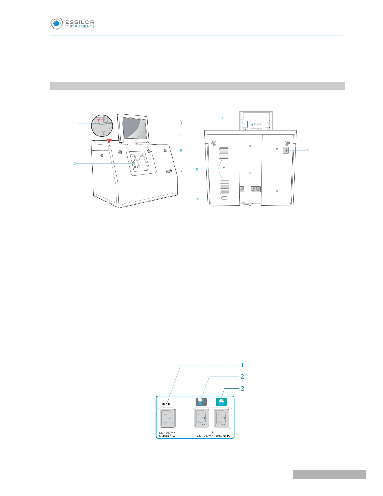
1. DESCRIPTIVE DIAGRAMS
This section consists of descriptions and lists of accessories.
1. USB plug
2. Trough
3. Screen
4. ON/OFF button
5. Cycle start/stop button
6. Barcode reader
7. Screen tilt buttons
8. Fans
9. Manufacturer plate
10. Main switch
Connectors
USER MANUAL> I. FIRST STEPS WITH PRO-E
11
Pro-E 600_Pro-E 700 > v1 -10.18
Page 12

1. Power socket
2. Solenoid valve socket
3. Pump socket (tank + pump) / Solenoid valve socket (town)
Accessories
Stylus
Posiblock removal pliers
Triangular key
White dressing stone for finishing wheel
Square dressing stone for polishing wheel
Transport wedges to be kept
Accessory box
Use :
• 22 mm posiblock holder
• 18 x 14 mm posiblock holder
• 22 mm stop
• 18 x 14 mm stop
• Mill/drill bit replacement tool (blocking key)
• Ø 1.0 mm drill bit (quantity 2, including one mounted on the module)
• Ø 0.8 mm drill bit (quantity 2)
• Ø 1.5 mm edging mill bit (quantity 2, including one mounted on the module)
• Ø 20 mm grooving wheel
• Chamfering wheel
• Step bevel wheel
• Torque wrench
• High-base edging wheel
• Metal ruler
• Modeling clay
• Description pamphlet of the accessories box
Maintenance
• Blocking key for tool changes (drill bit/mill bit)
• Adjustable wrench for tool changes (drill bit/mill bit)
• Accessory for Step bevel wheel assembly/dismantling
• Adjustable wrench for tool changes (drill bit, mill bit, chamfering wheel)
Options
• Open or closed circuit spraying kit
• Milling chip recovery tray
• Posiblock holder and “Weco” posiblock stop accessory kit
• M’Eye Sign Box
• Essibox
Connection accessories
• 220 V power cable
• RJ45 cable for the tracer-edger connection
• Essibox connection cable
Pro-E 600_Pro-E 700 > v1 -10.18
12
USER MANUAL> I. FIRST STEPS WITH PRO-E
Page 13
• Wastewater evacuation pipe with attachment ring
• 2 connectors to clip onto two internal water pipes and connect to the rinsing kit
2. USING THE EDGER
In this section, you will find all the information concerning the following:
• Turning on (F p.13) andoff (F p.13) the edger,
• the use of the touch screen and the keyboards (F p.14),
• the description of the work screens of the edger (F p.15).
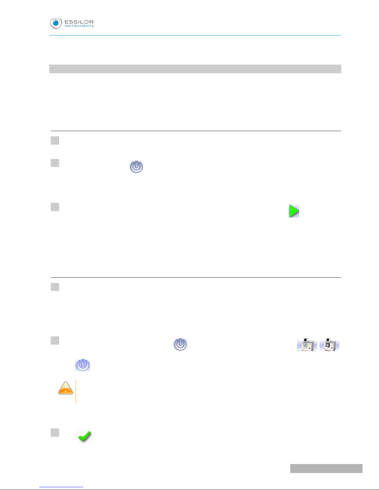
a. Turning on the edger
Press the main switch, located behind the edger on the left, to power it up.
Press the ON/OFF button located under the touch screen.
The edger will initialise.
On the edger screen, press on the “cycle start” button on the front surface or on the icon to end the
initialization phase.
A beep indicates that initialization was successful.
The edger is ready for use when the initial screen is displayed.
b. Switching off the edger
Before switching off the edger:
• Check that there is no glass in the trough
• Check that the lens clamp shafts are loosened and that the trough door is open
• Go to the edging screen.
Press the ON/OFF button for a short time located under the touch screen or press / ,
then .
Do not press the ON/OFF button for several seconds. This would result in shut-down of the
machine and an error message would be displayed at the next switch-on.
A confirmation message is displayed on the screen.
Press to confirm.
>
>
>
1
2
3
1
2
3
USER MANUAL> I. FIRST STEPS WITH PRO-E
13
Pro-E 600_Pro-E 700 > v1 -10.18
Page 14
The edger will switch off.
Extended period of non-use
For a prolonged period of non-use (a few days), it is preferable to turn off the edger using the main
switch.
It must be turned off at least once a week.
c. Using the touch screen and keypads
Using the touch screen
Use the stylus supplied with the machine to use with the touch screen.
You can also touch the screen with your finger.
• If the screen is not sensitive enough to finger pressure, press lightly with a fingernail.
• If the response area does not correspond to the position of the key, you need to calibrate the touch
screen. For further information, refer to the section Maintenance and servicing > Check and calibrate
> Calibrate the touch screen (F p.154).
• Never press hard on the screen as this could break it.
• Never press on the screen with sharp objects such as pens, scissors, clamps, etc.
• Screen breakage is not covered by the guarantee.
On the screen, press the icon buttons to access the desired menus and job functions .
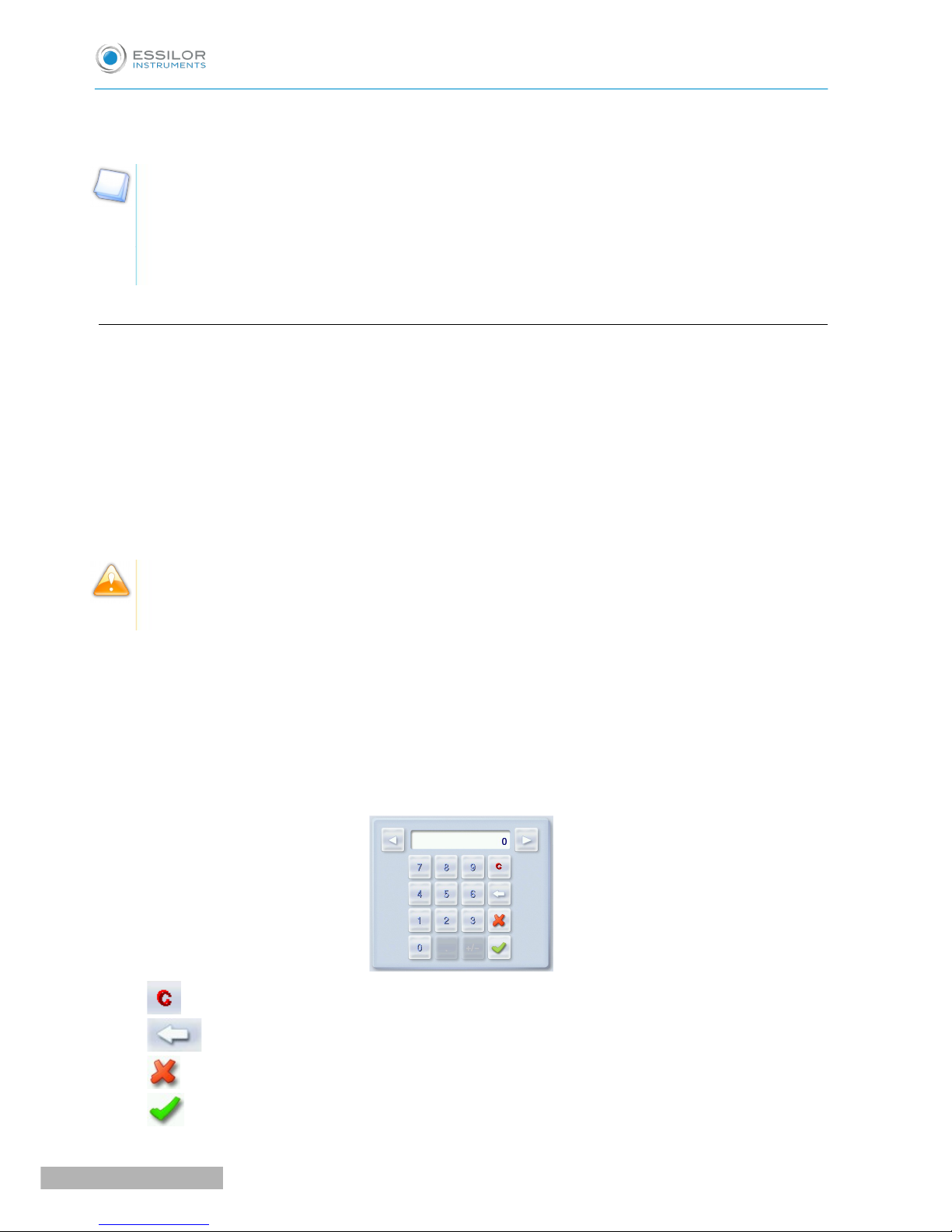
Using the keypads
When you need to enter or modify data, two types of keypads are automatically displayed, according to the
information to be entered.
• The numeric keypad is displayed for entering values.
• Reset the fields
• Go back
• Cancel and go back to the work screen
• Confirm
>
Pro-E 600_Pro-E 700 > v1 -10.18
14
USER MANUAL> I. FIRST STEPS WITH PRO-E
Page 15
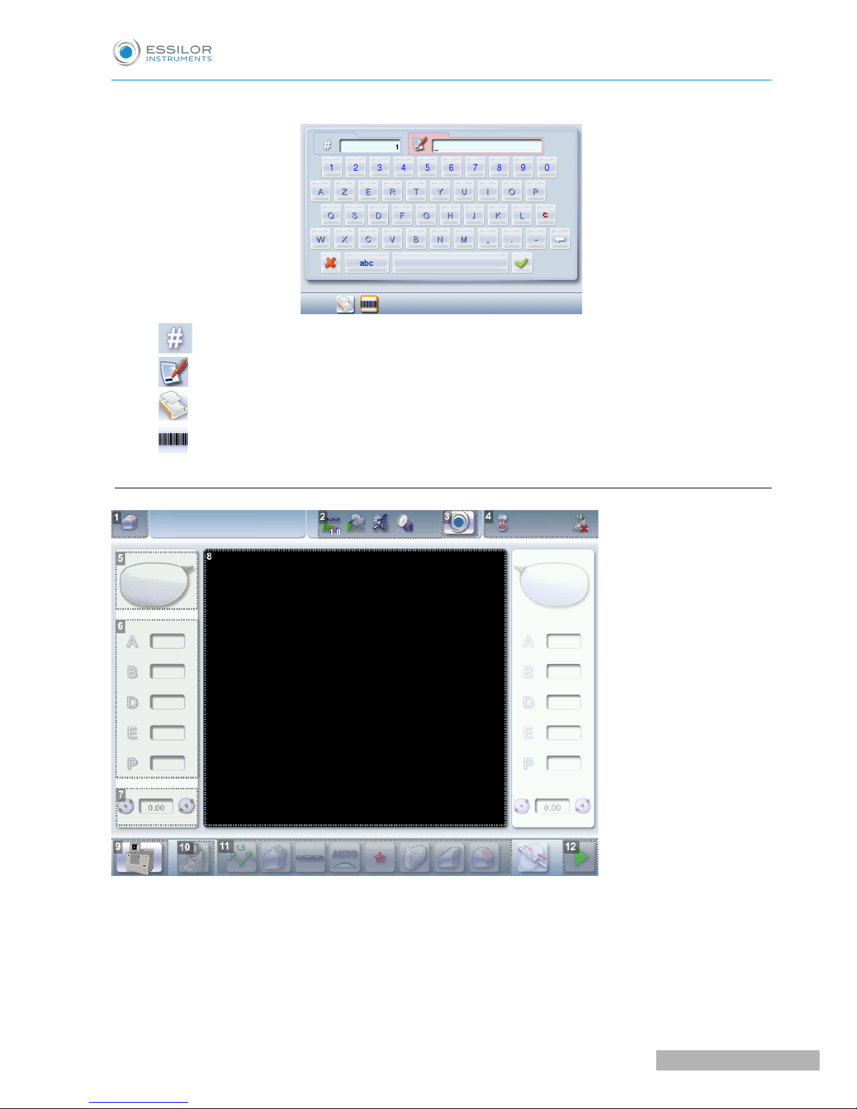
• The alphanumeric keypad is displayed to save or search for jobs.
• Job ID
• Job reference (alphanumeric characters)
• Collection list (when the edger is connected to a Essilor range tracer)
• Job list
&
d. Edging screen
1. Work screen indicator
2. Tool wear indicator
3. Settings
4. Devices connected
5. Active eye
USER MANUAL> I. FIRST STEPS WITH PRO-E
15
Pro-E 600_Pro-E 700 > v1 -10.18
Page 16

6. Information on the shape
7. Size increase/reduction
8. Work area
9. Turning off the product/edging screen
or
10. Job call: Tracer menu
11. Actions available for the current screen
12. Start the edging cycle
Detailed functions
For more information, consult the section Edging a lens > Work environment of the edger > Captioned
screen. (F p.20)
Pro-E 600_Pro-E 700 > v1 -10.18
16
USER MANUAL> I. FIRST STEPS WITH PRO-E
Page 17

II. EDGING A LENS
Page 18

Pro-E 600_Pro-E 700 > v1 -10.18
18
USER MANUAL> II. EDGING A LENS
Page 19

This chapter describes the work environment of the edger and the procedures for edging any type of lens:
• Edger working environment (F p.19)
• Perform a Beveling (F p.24)
• Beveling for a high-base frame (F p.32)
• Perform a Step bevel, (F p.40)
• Grooving (F p.49)
• Produce a Flat-edge finish (F p.57)
• Do a mixed job (F p.57)
• Perform a Drilled job (F p.62)
• Perform a Polishing (F p.67)
• Perform a Chamfering (F p.67)
• Perform a Retouching (F p.68)
• Perform a “Super Chamfer” (F p.70) (Pro-E 700)
• Perform a Chemistrie job (F p.72) TM (Pro-E 700)
• Perform a Half-Jacket job (F p.81) (Pro-E 700)
• Create an engraving or a creative shape (F p.100) (Pro-E 700)
1. EDGER WORKING ENVIRONMENT
This section describes the edger working environment and the initial stages of the edging of a lens.
• Description of the edging screen (F p.20)
• Shape call-up procedure (F p.22)
• Putting the lens in place (F p.22)
USER MANUAL> II. EDGING A LENS
19
Pro-E 600_Pro-E 700 > v1 -10.18
Page 20
•
a. Menu screen
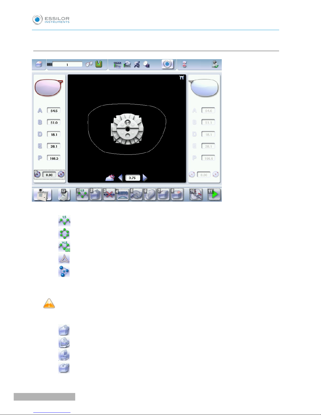
1. Lens material
◦ Plastic lens -index 1.5
&
◦ Polycarbonate lens
◦ Medium or high index plastic lens - index > 1.5
◦ Trivex lens
TM
◦ Tribrid lens
TM
The configuration of the edging cycles depends on the type of material. An incorrect choice may result in
material damage.
The Pro-E 600 edger does not edge glass lenses.
2. Type of finish
◦ Bevel
◦ High-base bevel
◦ “Step”/“Half-Jacket” bevel
◦ Groove
Pro-E 600_Pro-E 700 > v1 -10.18
20
USER MANUAL> II. EDGING A LENS
Page 21

◦ Flat-edge finish
◦ Mixed job
3. Drilling
◦ Drilling enabled
◦ Drilling disabled
4. Edging mode
◦ Automatic mode
The finish parameters are automatically calculated according to the information acquired when
tracing the frame and feeling the lens.
◦ Customized mode
The finish parameters can be fully customized.
5. Type of cycle
◦ Milling cycle
This cycle is recommended for lenses with a hydrophobic coating. It works with all types of
materials. Milling involves a specific feeling cycle: the edger will feel the contour of the shape to
be edged twice, then four feeling operations will be required every 90° to define the segments to
be cut.
◦ 2 stars Cycle
For all types of material. This cycle offers a more sophisticated edging mode than the standard
cycle, dedicated to thin lenses or to hydrophobic lenses when milling is not possible (lens too
quick for example).
◦ Standard cycle
For all types of material.
6. Polishing
◦ Polished lens
◦ Non-polished lens
7. Front surface chamfering
◦ Small chamfer
◦ Large chamfer
◦ No chamfering
8. Rear surface chamfering
◦ Small chamfer
◦ Large chamfer
USER MANUAL> II. EDGING A LENS
21
Pro-E 600_Pro-E 700 > v1 -10.18
Page 22

◦ No chamfering
9. Size reduction/increase (mm)
10. Manual lens clamping
Press and hold to close the lens clamp shafts manually.
11. Start the edging cycle
The door closing and lens clamping are automatic.
Function also available via the “cycle start” button on the front surface.
Always browse from left to right: depending on your selection, certain menus will be available while
others will not.
Your habits taken into account
The edger memorizes your working habits: as time goes by, the buttons of the functions you use most
often will be displayed by default.
b. Calling up a shape
There are 3 ways of calling up the shape you want to edge:
• Calling up the current job:
> Press to display the shape being processed on the tracer.
• Calling up the number of a shape saved on the tracer:
> Press for a few seconds to open the numeric keypad.
> You can then call up a shape via the ID allocated to it.
• Job call via a barcode:
> Scan the barcode using the barcode reader (optional).
Always lock down your 2 lenses before proceeding with the edging. If a job in the course of modification on
the tracer (display of the symbol beside the reference) is called up on the edger, a warning message is
displayed.
> Press to continue and display the job on the edger. The modifications underway are then ignored.
> Press to prevent the display of the job and finish the modifications underway on the tracer.
A reminder of the type of posiblock required is displayed on the shape. It is crucial to use the proper
accessory to edge the lens. Otherwise, an error message is displayed at the start of the cycle.
c. Lens set-up and feeling
Prerequisite: the lens must be centered and blocked before placing it in the edger.
Pro-E 600_Pro-E 700 > v1 -10.18
22
USER MANUAL> II. EDGING A LENS
Page 23
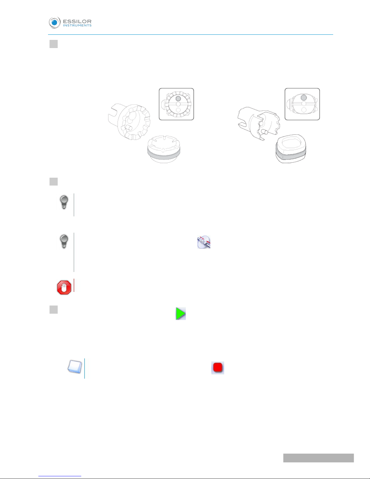
Check that the posiblock holder and the stop correspond to the posiblock used. Otherwise, you will need
to remove them from the lens clamp shafts and replace them with the tools matching the diameter of the
posiblock.
• For a 22 mm posiblock • For an 18 × 14 mm posiblock
Place the lens in the posiblock holder.
Place the metal peg of the posiblock upwards and the positioner downwards: a magnet is used to
hold the lens in position on the axis.
You can clamp the lens manually by pressing . Manual lens clamping is particularly suited to
hydrophobic lenses, thick lenses and high-camber lenses, as it ensures that the lens won't come
off the pad before clamping.
Make sure you move your hand well away before you start the edging cycle.
Press the “cycle start” button (front face) or
The door closes then the lens clamping operation starts.
The size of the posiblock holder is checked then the feeling cycle starts.
To interrupt the feeling cycle at any time, press .
>
>
1
2
3
USER MANUAL> II. EDGING A LENS
23
Pro-E 600_Pro-E 700 > v1 -10.18
Page 24
As the lens is felt, its shape appears on screen. The double tracing represents the profile of the front
surface of the shape (inner shape) and its rear surface (outer shape).
In the case of edging mode selection:
• automatic, you do not have to configure anything, all the data is automatically recovered from
the tracer. The lens edging starts automatically after the feeling cycle.
• customized, the finish parameters can be fully customized.
For further information, refer to the section concerning your type of finish.
The different lens edging stages appear on the screen.
2. PERFORM A BEVELING
This section describes the procedures for the creation of a bevel:
• In automatic mode (F p.25), you do not have to configure anything. All the data is automatically
retrieved from the tracer. The lens edging starts automatically after the feeling cycle.
• In customized mode (F p.27), you can opt for front/rear surface tracking, a distributed bevel,
lens curve tracking or frame rim tracking. You can also do the following:
>
>
>
Pro-E 600_Pro-E 700 > v1 -10.18
24
USER MANUAL> II. EDGING A LENS
Page 25
◦ a general modification of the bevel curve (F p.29)
◦ a modification at a point of the bevel curve (F p.30)
◦ a displacement of the bevel curve (F p.31)
• You can consult the description of the customized bevel screen (F p.26).
a. Automatic beveling
Call up the desired shape located on the tracer or on the job management program.
The shape is displayed on the edger work screen.
After the tracing of a rimmed frame:
• The bevel finish is selected by default.
• The automatic mode is selected by default.
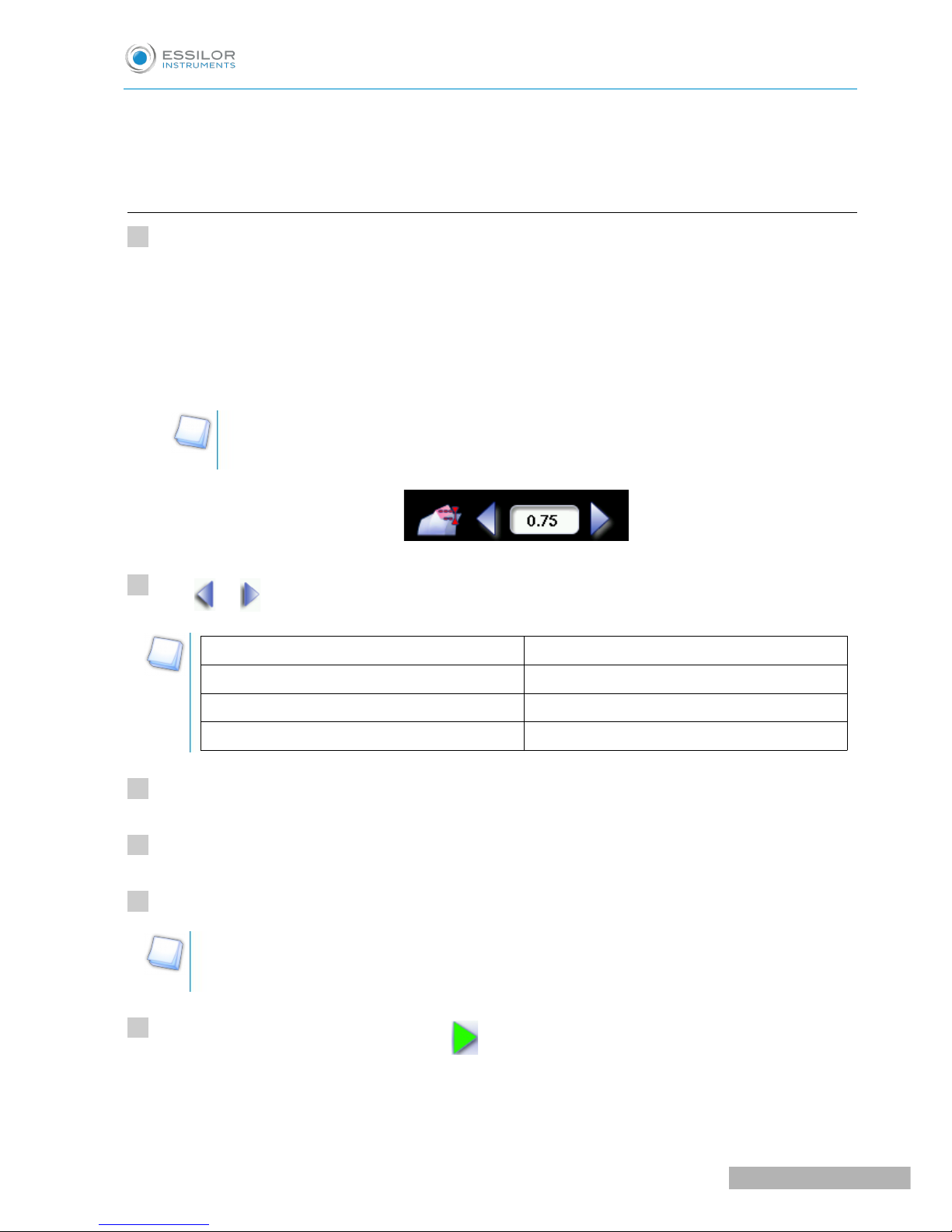
If you want to produce a bevel less than 0.75mm high, configure the bevel directly on the
screen.
Press and to adjust the height of the bevel.
Height (mm)
By default 0.75
Minimum 0.30
Maximum 0.75
Select lens material.
Select the type of cycle.
Choose whether or not to polish and/or chamfer your lens.
For more information, consult the section Edging a lens > Perform a polishing (F p.67) and Edging a
lens > Perform a chamfering (F p.67).
Press the “cycle start” button (front face) or .
The door closes, the lens is clamped, then the feeling operation starts.
The edging cycle starts.
>
>
>
>
1
2
3
4
5
6
USER MANUAL> II. EDGING A LENS
25
Pro-E 600_Pro-E 700 > v1 -10.18
Page 26
When the edging cycle is finished, the retouch screen is displayed.
Press to release the lens.
If necessary, retouch the lens.
Otherwise, start edging the second lens. Select the lens directly on the screen, on the left or right of the
work area.
The edging screen for the second lens is displayed. All finishes chosen and the modifications made
are kept.
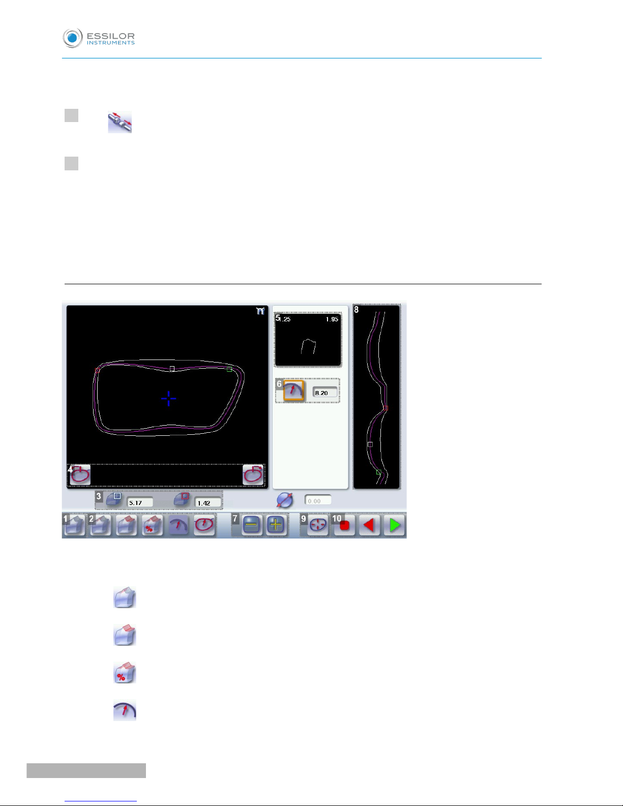
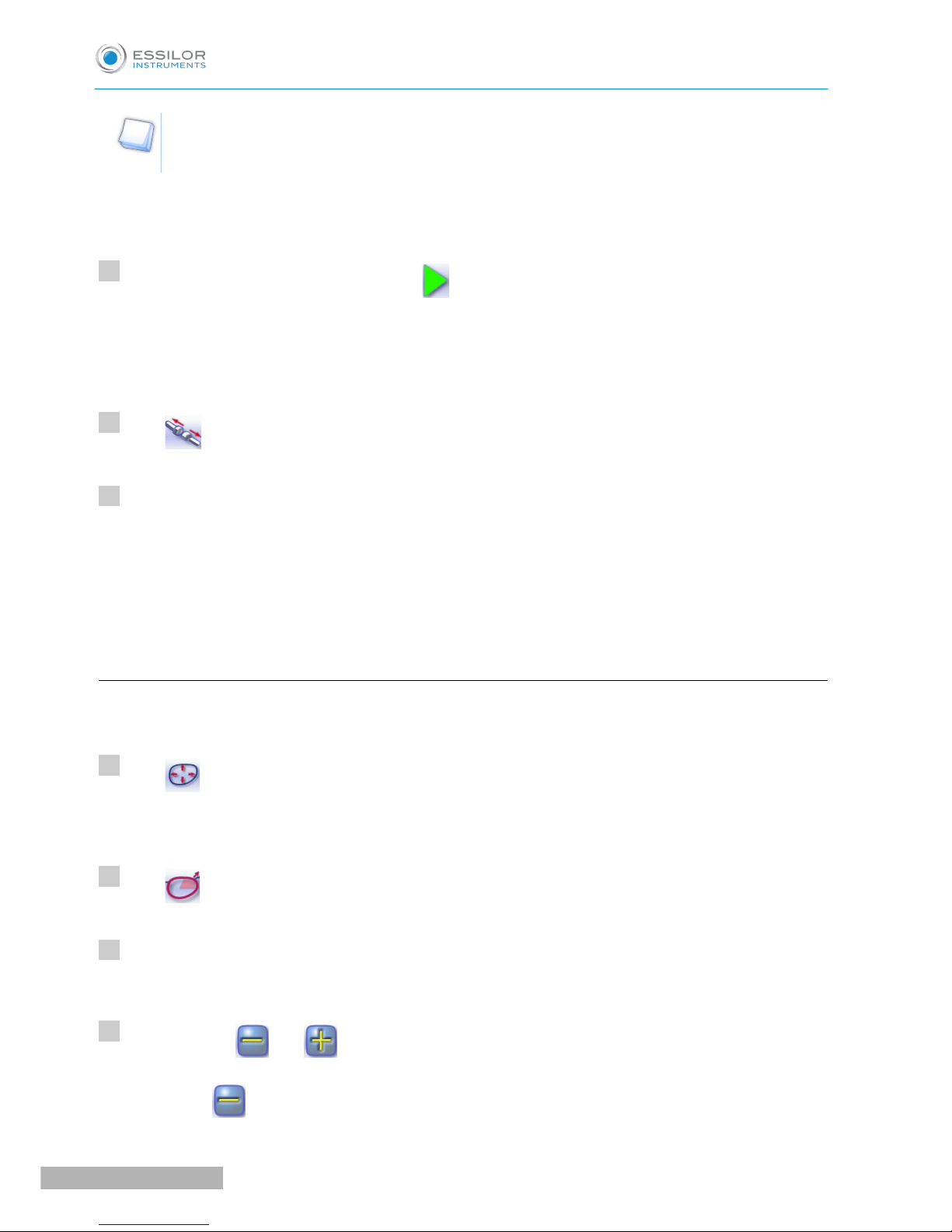
b. Legend screen for customized bevels
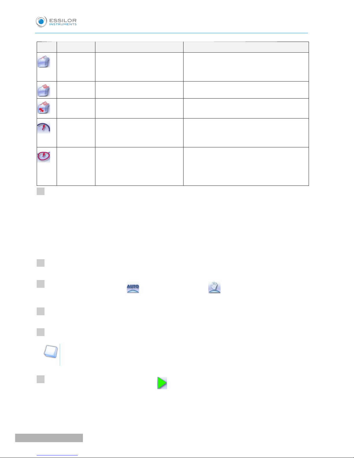
1. Automatic bevel
2. Customized bevel
◦ Front surface tracking: the crest of the bevel is positioned at a constant distance from the
front surface.
◦ Rear surface tracking: the crest of the bevel is positioned at a constant distance from the
rear surface.
◦ Distributed bevel: the position of the crest of the bevel is proportional to the thickness of
the lens, with respect to the front surface.
◦ Lens curve tracking: the camber of the bevel is adjustable.
>
>
7
8
Pro-E 600_Pro-E 700 > v1 -10.18
26
USER MANUAL> II. EDGING A LENS
Page 27

◦ Frame rim tracking: the bevel tracks the groove precisely, according to the data obtained
on frame tracing.
3. Lens thickness
◦ Maximum lens thickness - represented by the white square along the shape.
◦ Minimum lens thickness - represented by the red square along the shape.
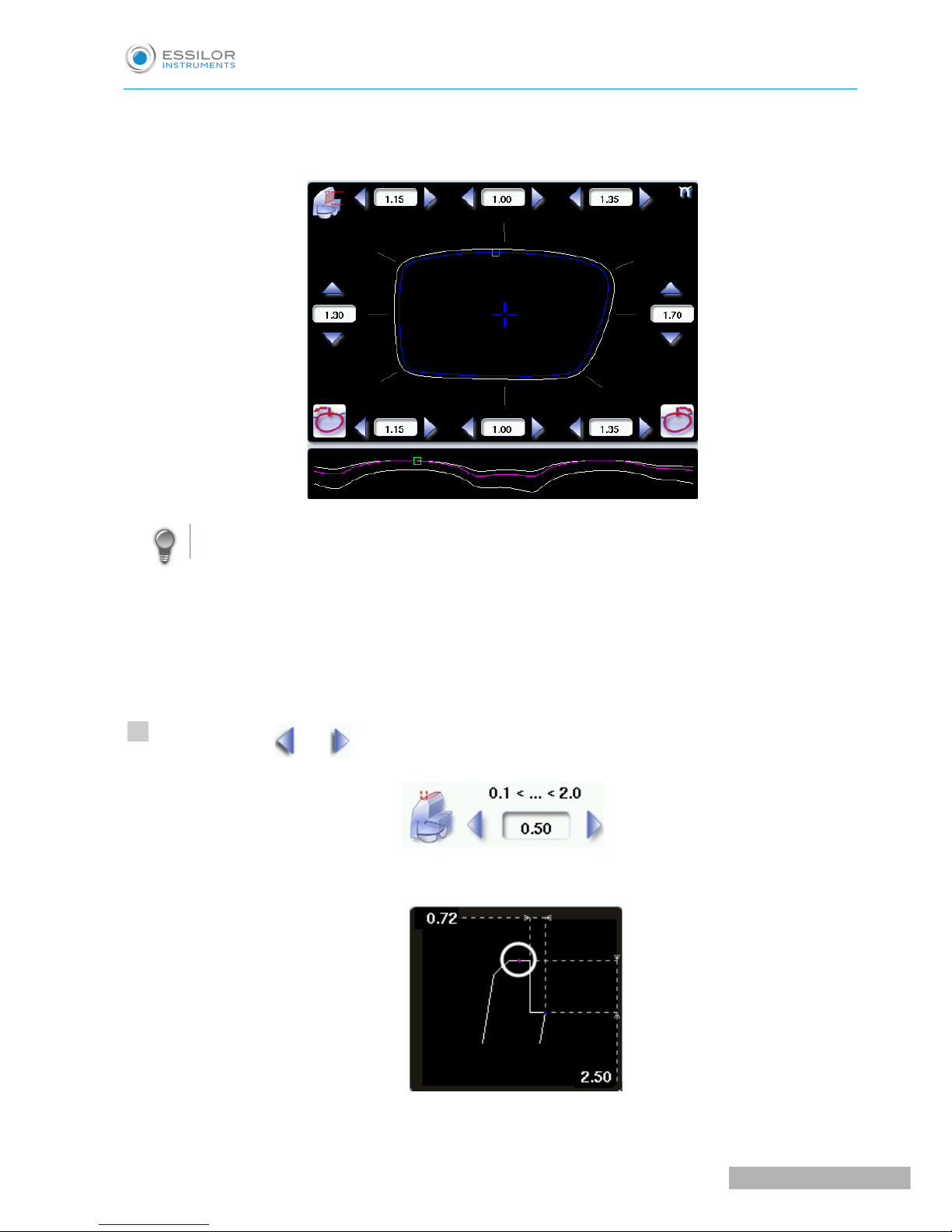
4. Cursor movement
The cursor is represented by the green square along the shape. To move it, select it directly or use the
and buttons.
5. Zoom window
Represents the bevel profile and indicates the distance between the bevel crest and the front and rear
surfaces of the lens at the cursor position.
6. Bevel distribution value
Distribution value modifiable for:
◦ front/rear surface tracking
◦ a distributed bevel
◦ lens curve tracking
7. Modify the selected value
Reduce or increase the distribution value.
8. Bevel trajectory
Flat representation of the lens making it possible to assess the distances between the bevel crest and the
front & rear surfaces of the lens.
9. Trajectory modification
◦ General modification of the bevel curve
◦ Modification of the bevel curve at a particular point
◦ Displacement of the bevel curve
10. Navigation
◦ Stop the cycle
◦ Return to the main edging screen without saving your changes.
◦ Start the edging cycle
c. Customized beveling
The use of the customized bevel depends on 2 parameters: the frame and the lens. Before starting your job,
identify the major constraint.
USER MANUAL> II. EDGING A LENS
27
Pro-E 600_Pro-E 700 > v1 -10.18
Page 28
BEVEL FRAME LENS ADVANTAGES
Classic Lens for which the front surface
base is approximately equal to the
frame base.
Makes it possible to do an aesthetically pleasing
job. The lens material does not protrude beyond
the front of the frame.
Classic Lenticular lens&, Executive lens&Makes it possible to do a job with specific lenses.
Classic Thin lens Makes it possible to balance out the bevel when
thin lenses are used.
Flat base
High base
Thin lens for which the front
surface base is approximately
equal to the frame base.
Makes it possible to retrieve the frame base in a
pattern tracing (base = 0).
Particular
groove
(groove with
meniscus&)
Thin lens for which the base is
approximately equal to the
meniscus of the groove.
Compliance with original shape.
Job using a specific frame.
Call up the desired shape located on the tracer or on the job management program.
The shape is displayed on the edger work screen.
After the tracing of a rimmed frame:
• The bevel finish is selected by default.
• The automatic mode is selected by default.
Select lens material.
Change the edging mode. Press to select customized mode .
Select the type of cycle.
Choose whether or not to polish and/or chamfer your lens.
For more information, consult the section Edging a lens > Perform a polishing (F p.67) and Edging a
lens > Perform a chamfering (F p.67).
Press the “cycle start” button (front face) or .
The door closes, the lens is clamped and then felt.
The customized bevel finish screen is displayed.
>
>
>
>
1
2
3
4
5
6
Pro-E 600_Pro-E 700 > v1 -10.18
28
USER MANUAL> II. EDGING A LENS
Page 29
Select the type of customized bevel you want to do.
To avoid reproducing defects when tracking a frame rim, check that the frame groove is in perfect
condition and that the hinges are properly closed. All groove imperfections will be reproduced.
Press and to adjust the distribution value if required.
Press .
The edging cycle starts.
When the edging cycle is finished, the retouch screen is displayed.
Press to release the lens.
If necessary, retouch the lens.
Otherwise, start edging the second lens. Select the lens directly on the screen, on the left or right of the
work area.
The edging screen for the second lens is displayed. All finishes chosen and the modifications made
are kept.
d. Modifying the bevel curve
Once you have configured the desired type of customized bevel, you can complete your customization by
moving the bevel curve towards the front or rear surface of the lens so it takes on its shape.
Press from the customized bevel finish screen.
You will access the trajectory modification screen.
Press to select the general modification of the bevel curve.
Use the buttons and to move the bevel curve:
• Press to move the curve towards the front surface of the lens.
• Press to move the curve towards the rear surface of the lens.
>
>
>
>
7
8
9
10
11
1
2
3
USER MANUAL> II. EDGING A LENS
29
Pro-E 600_Pro-E 700 > v1 -10.18
Page 30
The curve cannot be moved more than the minimum distance between the front and rear surfaces
observed on the bevel before the modification.
The position of the bevel as well as the distances between the crest of the bevel and the front and
rear surfaces of the lens are displayed in the zoom window at the position of the cursor.
Press the “cycle start” button (front face) or .
The edging cycle starts.
When the edging cycle is finished, the retouch screen is displayed.
Press to release the lens.
If necessary, retouch the lens.
Otherwise, start edging the second lens. Select the lens directly on the screen, on the left or right of the
work area.
The edging screen for the second lens is displayed. All finishes chosen and the modifications made
are kept.
e. Modifying the bevel curve at a particular point
Once you have configured the desired type of customized bevel, you can complete your customization by
partially moving the bevel curve towards the front or rear surface of the lens so it takes on its shape.
Press from the customized bevel finish screen.
You will access the trajectory modification screen.
Press to select modification of the bevel curve at a particular point.
Using the cursor, select the point on the curve that you want to move or click directly on the position of
the shape you want to modify.
Use the buttons and to move the point on the selected curve.
• Press to move it towards the front surface of the lens.
>
>
>
>
>
4
5
6
1
2
3
4
Pro-E 600_Pro-E 700 > v1 -10.18
30
USER MANUAL> II. EDGING A LENS
Page 31

• Press to move it towards the rear surface of the lens.
The curve cannot be moved more than the minimum distance between the front and rear surfaces
observed on the bevel before the modification.
The position of the bevel as well as the distances between the crest of the bevel and the front and
rear surfaces of the lens are displayed in the zoom window at the position of the cursor.
Press the “cycle start” button (front face) or .
Press to go back to the customized bevel finish screen.
For the second lens, the customized bevel icon is pre-selected and the trajectory modification icon is
displayed.
f. Displacing the bevel curve
The displacement of the bevel curve makes it possible to move the bevel without modifying its curve.
Press from the customized bevel finish screen.
You will access the trajectory modification screen.
Press to select the displacement of the bevel curve.
Use the and buttons to displace the bevel curve:
• Press to displace it towards the front surface of the lens.
• Press to displace it towards the rear surface of the lens.
The position of the bevel as well as the distances between the crest of the bevel and the front and
rear surfaces of the lens are displayed in the zoom window at the position of the cursor.
Press the “cycle start” button (front face) or .
The edging cycle starts.
When the edging cycle is finished, the retouch screen is displayed.
>
>
>
>
>
>
5
1
2
3
4
USER MANUAL> II. EDGING A LENS
31
Pro-E 600_Pro-E 700 > v1 -10.18
Page 32

Press to release the lens.
If necessary, retouch the lens.
Otherwise, start edging the second lens. Select the lens directly on the screen, on the left or right of the
work area.
The edging screen for the second lens is displayed. All finishes chosen and the modifications made
are kept.
3. PERFORM A HIGH-BASE BEVEL
This section describes the procedures for the creation of a high-base bevel:
• Description of the high-base bevel screens, (F p.33)
• Perform a high-base bevel in “automatic trajectory” mode or “front surface tracking” mode. (F p.34)
The use of the high-base bevel is determined by two parameters: frame and lens.
• Concerning the lens, the main constraint is the thickness of the nasal and temporal edges.
• Concerning the frame, the crucial elements are the bridge and shape of the groove. The hinge is an
additional factor in the case of a metal frame, the arms for a plastic frame.
For this job, the lens base must always match the frame base perfectly. Too great a difference
between the two could be detrimental to the quality of your job.
Cross-section of a high-base bevel
1: Shelf bevel value
2: Width of the flat side of the bevel
3. Front surface tracking value
>
5
6
Pro-E 600_Pro-E 700 > v1 -10.18
32
USER MANUAL> II. EDGING A LENS
Page 33

a. Captioned screens
1. High-base bevel screen “front surface monitoring”
2. Work area
Image of the shape to be edged:
Frame shape at bottom of groove
Bevel trajectory on rear surface
Bevel trajectory on rear surface if the lens used is too thin to achieve the desired finish.
3. Cursor movement
The cursor is represented by the square located along the shape. To move it, select it directly or use the
and buttons.
4. Zoom window
Represents the bevel profile at the position of the cursor.
5. Shelf bevel value (8 or 4 values)
◦ Nasal (the value must be between 0.25 and 3 mm)
◦ Mid-nasal (the value must be between 0.25 and 3 mm)
◦ Upper (the value must be between 0.25 and 3 mm)
◦ Mid-upper (the value must be between 0.25 with 3 mm)
◦ Temporal (the value must be between 0.25 and 3 mm)
◦ Mid-temporal (the value must be between 0.25 and 3 mm)
◦ Lower (the value must be between 0.25 and 3 mm)
◦ Mid-lower (the value must be between 0.25 and 3 mm)
6. Width of the flat side of the bevel
The value of the flat side of the bevel must be between 0.1 mm and 1 mm.
7. Front surface tracking value
The value of front surface tracking must be between 0 mm and 1.3 mm. This value is definable only in
the “front surface tracking” screen.
USER MANUAL> II. EDGING A LENS
33
Pro-E 600_Pro-E 700 > v1 -10.18
Page 34

8. Frame base
9. Lens base
10. Bevel Base_Range of values of the lens base necessary for the frame
If the lens base used is out of range: the range values are shown in red.
11. Reminder of size reduction/increase applied to lens diameter
12. Window showing the bevel trajectory on the lens section
Centre of the flat side of the bevel
Front surface/rear surface of lens
13. Number of shelf bevel values
Transition from 4 to 8 shelf bevel values.
Transition from 8 to 4 shelf bevel values.
14. Navigation
◦ Stop the cycle
◦ Return to the main edging screen without saving your changes
◦ Start the edging cycle
15. High base bevel screen “automatic trajectory”
In this screen, the trajectory on the lens section cannot be configured: it is calculated automatically. This
calculation harmonises as best as possible, the lens base, the base of the frame and the shape.
b. High-base beveling
Call up the desired shape located on the tracer or on the job management program.
The shape is displayed on the edger work screen.
After the tracing of a high-base frame:
• The high-base finish is selected by default.
• The customized mode is selected by default.
In the high-base finish, you cannot polish your bevel. Nevertheless, the high-base wheel was
designed to create an equivalent finish for polycarbonate lenses.
It is possible to perform the polishing of the flat side of the bevel.
Select lens material.
Select the type of cycle.
>
>
1
2
3
Pro-E 600_Pro-E 700 > v1 -10.18
34
USER MANUAL> II. EDGING A LENS
Page 35

Choose to create or not create a small or large chamfer on the rear surface of the lens.
“Super Chamfer” is not available for the high-base bevel finish.
For more information, consult the section Edging a lens > Perform a polishing (F p.67) and Edging a
lens > Perform a chamfering (F p.67).
Press the “cycle start” button (front face) or .
The door closes, the lens is clamped and then felt.
The high-base bevel finish “automatic trajectory” screen is displayed by default.
By default, the edger shows the values corresponding to the frame material (metal or plastic).
Check and modify these values according to the thickness of your lens and your frame.
You can:
• produce a high-base bevel in mode “automatic trajectory”, (F p.36)
• high-base bevel in “front surface tracking” mode. (F p.37)
>
>
4
5
USER MANUAL> II. EDGING A LENS
35
Pro-E 600_Pro-E 700 > v1 -10.18
Page 36

High-base bevel in “automatic trajectory” mode
Press to select the bevel in “automatic trajectory ” mode.
The following screen will appear:
Press the buttons and on the right of your screen to modify the width of the flat side of the bevel.
The result can be viewed in the zoom window.
Press the and buttons to modify the shelf bevel value at each point of the shape in
each area:
• Temporal
• Mid-temporal
• Nasal
• Mid-nasal
• Upper
• Mid-upper
• Lower
• Mid-lower
>
>
1
2
3
Pro-E 600_Pro-E 700 > v1 -10.18
36
USER MANUAL> II. EDGING A LENS
Page 37

Move the cursor along the shape to see the bevel profile in the zoom window.
The edger calculates the shelf bevel value to be applied between each of the four points in each area.
The bevel trajectory on the rear surface is modified in the work screen. The result can be viewed in
the zoom window.
Press the “cycle start” button (front face) or .
The edging cycle starts.
When the edging cycle is finished, the retouch screen is displayed.
Press to release the lens.
If necessary, retouch the lens.
Otherwise, start edging the second lens. Select the lens directly on the screen, on the left or right of the
work area.
The edging screen for the second lens is displayed. All finishes chosen and the modifications made
are kept.
High-base bevel in “front surface tracking” mode
Press to select the bevel in “front surface tracking” mode.
>
>
>
>
>
4
5
6
1
USER MANUAL> II. EDGING A LENS
37
Pro-E 600_Pro-E 700 > v1 -10.18
Page 38

The following screen will appear:
Press the buttons and on the right of your screen to modify the width of the flat side of the bevel.
The result can be viewed in the zoom window.
Press the and buttons to modify the shelf bevel value at each point of the shape in
each area:
• Temporal
• Mid-temporal
• Upper
• Mid-upper
• Nasal
• Mid-nasal
• Lower
• Mid-lower
>
>
2
3
Pro-E 600_Pro-E 700 > v1 -10.18
38
USER MANUAL> II. EDGING A LENS
Page 39

Move the cursor along the shape to see the bevel profile in the zoom window.
The edger calculates the shelf bevel value to be applied between each of the four points in each area.
The bevel trajectory on the rear surface is modified in the work screen. The result can be viewed in
the zoom window.
Press the buttons and on the right of your screen to modify the value of front surface tracking.
The result can be viewed in the zoom window and the display window of the bevel trajectory on the
lens section.
Press the “cycle start” button (front face) or .
The edging cycle starts.
When the edging cycle is finished, the retouch screen is displayed.
Press to release the lens.
If necessary, retouch the lens.
Otherwise, start edging the second lens. Select the lens directly on the screen, on the left or right of the
work area.
The edging screen for the second lens is displayed. All finishes chosen and the modifications made
are kept.
>
>
>
>
>
>
4
5
6
7
USER MANUAL> II. EDGING A LENS
39
Pro-E 600_Pro-E 700 > v1 -10.18
Page 40

4. PERFORM A STEP BEVEL
A step bevel is strongly recommended for a high-base sports frame or a safety frame.
The step bevel finishing is active and available only if the tool is installed on the “small tools” module
(F p.168).
For more information, refer to the section Maintenance servicing> Changing edger tools > Installing
the Step ++ wheel (F p.168).
This section describes the procedures for the creation of a step bevel:
◦ description of the Step bevel screens (F p.41)
◦ perform a Step bevel in “automatic trajectory” mode (F p.44) or “front surface tracking” mode.
(F p.46)
The use of the step bevel is determined by two parameters: frame and lens.
• Concerning the lens, the main constraint is the thickness of the nasal and temporal edges.
• Concerning the frame, the crucial elements are the bridge and shape of the groove. The hinge is an
additional factor in the case of a metal frame, the arms for a plastic frame.
For this job, the lens base must always match the frame base perfectly. Too great a difference
between the two could be detrimental to the quality of your job.
Cross-section of a step bevel
1: Value of shelf bevel of rear surface
2: Width of the flat side of the bevel
3. Front surface tracking value
Pro-E 600_Pro-E 700 > v1 -10.18
40
USER MANUAL> II. EDGING A LENS
Page 41

a. Captioned screens
1. Automatic trajectory step bevel screen.
In this screen, the trajectory on the lens section cannot be configured: it is calculated automatically. This
calculation harmonises as best as possible, the lens base, the base of the frame and the shape.
2. Work area
Image of the shape to be edged:
Frame shape at bottom of groove
Bevel trajectory on rear surface
Bevel trajectory on rear surface if the lens used is too thin to achieve the desired finish.
3. Cursor movement
The cursor is represented by the square located along the shape. To move it, select it directly or use the
and buttons.
4. Zoom window
Represents the bevel profile at the position of the cursor.
5. Shelf bevel value (8 or 4 values)
◦ Nasal (the value must be between 0.40 and 5.3 5mm)
◦ Nasal (the value must be between 0.40 and 5.35 mm)
◦ Upper (the value must be between 0.40 and 5.35 mm)
◦ Intermediary upper (the value must be between 0.40 and 5.35 mm)
◦ Temporal (the value must be between 0.40 and 5.35 mm)
◦ Intermediary temporal (the value must be between 0.40 and 5.35 mm)
◦ Lower (the value must be between 0.40 and 5.30 mm)
◦ Intermediary lower (the value must be between 0.40 and 5.35 mm)
6. Width of the flat side of the bevel
The value of the flat side of the bevel must be between 0.1 mm and 2 mm.
7. Back chamfer of assembly aid
USER MANUAL> II. EDGING A LENS
41
Pro-E 600_Pro-E 700 > v1 -10.18
Page 42

8. Bevel tilt
9. Front surface tracking step bevel screen
10. Front surface tracking value
The value of front surface tracking must be between 0 mm and 1.3 mm. This value is definable only in
the “front surface tracking” screen.
11. Frame base
12. Lens base
13. Bevel Base_Range of values of the lens base necessary for the frame
If the lens base used is out of range: the range values are shown in red.
14. Reminder of size reduction/increase applied to lens diameter
15. Window showing the bevel trajectory on the lens section
Centre of the flat side of the bevel
Front surface/rear surface of lens
16. Number of shelf bevel values
Transition from 4 to 8 shelf bevel values.
Transition from 8 to 4 shelf bevel values.
Transition into free shelf-bevel creation mode (Half Jacket specific_option)
17. Navigation
◦ Stop the cycle
◦ Return to the main edging screen without saving your changes.
◦ Start the edging cycle
b. Perform a Step bevel
Call up the desired shape located on the tracer or on the job management program.
The shape is displayed on the edger work screen.
After the tracing of a high-base frame:
• The step finish is selected by default.
• The customized mode is selected by default.
In the step finish, you cannot polish your bevel. Nevertheless, the step wheel was designed to
create a finish that is equivalent to polycarbonate lenses.
You have the option of polishing the flat side of the bevel.
>
>
1
Pro-E 600_Pro-E 700 > v1 -10.18
42
USER MANUAL> II. EDGING A LENS
Page 43

Press to select the Step bevel.
The button appears grayed if the step bevel wheel was not mounted beforehand: .
Select lens material.
Select the type of cycle.
Choose or not to chamfer your lens.
If you have a pro-E 700, it is to recommend to carry out a “Super Chamfer” .
For more information, consult the section Edging a lens > Perform a polishing (F p.67) and Edging a
lens > Perform a chamfering (F p.67).
Press the “cycle start” button (front face) or .
The door closes, the lens is clamped and then felt.
The “automatic trajectory” step finish screen is displayed by default.
By default, the edger shows the values corresponding to the frame material (metal or plastic).
Check and modify these values according to the thickness of your lens and your frame.
You can:
• perform a step bevel in “automatic trajectory” mode (F p.44),
In this mode, the bevel trajectory follows the base of the frame as closely as possible.
• perform a step bevel in “front surface tracking” mode (F p.46).
In this mode, the trajectory of bevel follows the front surface lens base as closely as possible.
>
>
2
3
4
5
6
USER MANUAL> II. EDGING A LENS
43
Pro-E 600_Pro-E 700 > v1 -10.18
Page 44

Step bevel in “automatic trajectory” mode
Press to select the bevel in “automatic trajectory ” mode.
The following screen will appear:
Press the buttons and on the right of your screen to modify the width of the flat side of the bevel.
The result can be viewed in the zoom window.
Press on the buttons and to modify the shelf bevel value in each point of the shape in
each of the areas, 4 or 8 areas:
• Temporal
• Mid-temporal
• Upper
• Mid-upper
• Nasal
• Mid-nasal
>
>
1
2
3
Pro-E 600_Pro-E 700 > v1 -10.18
44
USER MANUAL> II. EDGING A LENS
Page 45

• Lower
• Mid-lower
Move the cursor along the shape to see the bevel profile in the zoom window.
The edger calculates the shelf bevel value to be applied between each of the four or eight points of
each area.
The bevel trajectory on the rear surface is modified in the work screen. The result can be viewed in
the zoom window.
Press to perform a back chamfer of the assembly aid.
The chamfer is selected .
The result can be viewed in the zoom window.
Press systematically to tilt of the bevel (mounting aid).
The bevel tilt is selected .
The result can be viewed in the zoom window.
>
>
>
>
>
>
4
5
USER MANUAL> II. EDGING A LENS
45
Pro-E 600_Pro-E 700 > v1 -10.18
Page 46

Press the “cycle start” button (front face) or .
The edging cycle starts.
When the edging cycle is finished, the retouch screen is displayed.
Press to release the lens.
If necessary, retouch the lens.
Otherwise, start edging the second lens. Select the lens directly on the screen, on the left or right of the
work area.
The edging screen for the second lens is displayed. All finishes chosen and the modifications made
are kept.
Step bevel in “front surface follow-up” mode
Press to select the bevel in “front surface tracking” mode.
The following screen will appear:
Press the and buttons to modify the shelf bevel value at each point of the shape in
each area:
• Temporal
• Mid-temporal
• Upper
• Mid-upper
• Nasal
>
>
>
>
6
7
8
1
2
Pro-E 600_Pro-E 700 > v1 -10.18
46
USER MANUAL> II. EDGING A LENS
Page 47
• Mid-nasal
• Lower
• Mid-lower
Move the cursor along the shape to see the bevel profile in the zoom window.
The edger calculates the shelf bevel value to be applied between each of the four or eight points of
each area.
The bevel trajectory on the rear surface is modified in the work screen. The result can be viewed in
the zoom window.
Press the buttons and on the right of your screen to modify the width of the flat side of the bevel.
The result can be viewed in the zoom window.
>
>
>
3
USER MANUAL> II. EDGING A LENS
47
Pro-E 600_Pro-E 700 > v1 -10.18
Page 48

Press the buttons and on the right of your screen to modify the value of front surface tracking.
The result can be viewed in the zoom window and the display window of the bevel trajectory on the
lens section.
Press to perform a back chamfer of the assembly aid.
The chamfer is selected .
The result can be viewed in the zoom window.
Press systematically to tilt of the bevel (mounting aid).
The bevel tilt is selected .
The result can be viewed in the zoom window.
>
>
>
>
>
4
5
6
Pro-E 600_Pro-E 700 > v1 -10.18
48
USER MANUAL> II. EDGING A LENS
Page 49

Press the “cycle start” button (front face) or .
The edging cycle starts.
When the edging cycle is finished, the retouch screen is displayed.
Press to release the lens.
If necessary, retouch the lens.
Otherwise, start edging the second lens. Select the lens directly on the screen, on the left or right of the
work area.
The edging screen for the second lens is displayed. All finishes chosen and the modifications made
are kept.
5. GROOVING
This section describes the procedures for the creation of a groove:
• In automatic mode (F p.50), you do not have to configure anything. All the data is automatically
retrieved from the tracer. The lens edging starts automatically after the feeling cycle.
• In customized mode (F p.52), you can perform a front/rear surface tracking, a distributed groove
or a lens curve tracking. You can also do the following:
◦ a general modification of the groove curve (F p.54)
◦ a modification at a point of the groove curve (F p.55)
◦ a displacement of the groove curve (F p.56)
• You can consult the description of the customized groove screen.
In certain cases, the lens base or thickness makes grooving impossible.
> An error message is displayed.
> The white central line becomes red on the entire contour of the lens.
>
>
>
7
8
9
USER MANUAL> II. EDGING A LENS
49
Pro-E 600_Pro-E 700 > v1 -10.18
Page 50

a. Automatic grooving
Call up the desired shape located on the tracer or on the job management program.
The shape is displayed on the edger work screen.
After tracing a pattern, demo lens or re-cut lens, without any drilling settings:
• the groove finish is selected by default.
• the automatic mode is selected by default.
If you wish to produce a groove the depth and the width of which are less than 0.60 mm:
Directly define the groove in the screen.
Press and to regulate the depth and the width of the groove
Depth (mm) Width (mm)
By default 0.60 0.60
Minimum 0.20 0.60
Maximum 1.20 1.20
Select lens material.
Select the type of cycle.
Choose whether or not to polish and/or chamfer your lens.
For more information, consult the section Edging a lens > Perform a polishing (F p.67) and Edging a
lens > Perform a chamfering (F p.67).
Press the “cycle start” button (front face) or .
The door closes, the lens is clamped and then felt.
The edging cycle starts.
When the edging cycle is finished, the retouch screen is displayed.
>
>
>
>
>
1
2
3
4
5
6
Pro-E 600_Pro-E 700 > v1 -10.18
50
USER MANUAL> II. EDGING A LENS
Page 51

Press to release the lens.
If necessary, retouch the lens.
Otherwise, start edging the second lens. Select the lens directly on the screen, on the left or right of the
work area.
The edging screen for the second lens is displayed. All finishes chosen and the modifications made
are kept.
b. Customized groove legend screen
1. Automatic groove
2. Customised grooving
◦ Front surface tracking: the middle of the groove is positioned at a constant distance from
the front surface.
◦ Rear surface tracking: the middle of the groove is positioned at a constant distance from
the rear surface.
◦ Distributed groove: the middle of the groove is positioned in proportion to the thickness of
the lens, with respect to the front surface.
◦ Lens curve tracking: the camber of the groove is adjustable.
3. Lens thickness
◦ Maximum lens thickness - represented by the white square along the shape
>
7
8
USER MANUAL> II. EDGING A LENS
51
Pro-E 600_Pro-E 700 > v1 -10.18
Page 52

◦ Minimum lens thickness - represented by the red square along the shape
4. Cursor movement
The cursor is represented by the green square along the shape. To move it, select it directly or use the
and buttons.
5. Zoom window
Distance between the edges of the groove and the front & rear surfaces of the lens at the position of the
cursor.
6. Groove settings
◦ Distribution value - according to the type of customized groove selected
◦ Groove depth (in mm)
◦ Groove width (in mm)
7. Modify the selected setting
8. Groove trajectory
Flat representation of the lens making it possible to measure the distances between the groove and the
front & rear surfaces of the lens.
9. Modify the trajectory
◦ General modification of the groove curve
◦ Modification of a point in the groove curve
◦ Displacement of the groove curve
10. Navigation
◦ Stop the cycle
◦ Return to the main edging screen without saving your changes
◦ Start the edging cycle
c. Customised grooving
The use of the customized groove depends on 2 parameters: the frame and the lens. Before starting your
job, identify the major constraint.
GROOVE FRAME LENS ADVANTAGES
Standard
groove
Lens for which the front surface
base is approximately equal to the
frame base.
Makes it possible to do an aesthetically pleasing job.
The lens material does not protrude beyond the front
of the frame.
Pro-E 600_Pro-E 700 > v1 -10.18
52
USER MANUAL> II. EDGING A LENS
Page 53

GROOVE FRAME LENS ADVANTAGES
Standard
groove
Lens for which the rear surface
base is not as high as the front
surface base.
Minimises the risks of the nylon thread coming out.
Standard
groove
Thin lens Makes it possible to balance out the groove when thin
lenses are used.
Flat base
High base
Thin lens for which the front
surface base is approximately
equal to the frame base.
In the event of pattern tracing (base = 0), makes it
possible to retrieve the frame base.
Call up the desired shape located on the tracer or on the job management program.
The shape is displayed on the edger work screen.
After tracing a pattern, demo lens or re-cut lens, without any drilling settings:
• the groove finish is selected by default.
• the automatic mode is selected by default.
Select lens material.
Change the edging mode. Press to select customized mode .
Select the type of cycle.
Choose whether or not to polish and/or chamfer your lens.
For more information, consult the section Edging a lens > Perform a polishing (F p.67) and Edging a
lens > Perform a chamfering (F p.67).
Press the “cycle start” button (front face) or .
The door closes, the lens is clamped and then felt.
The customized groove finish screen is displayed.
Select the type of customized groove you want to do.
Select the values you want to modify and press and to adjust them if necessary
>
>
>
>
1
2
3
4
5
6
7
8
USER MANUAL> II. EDGING A LENS
53
Pro-E 600_Pro-E 700 > v1 -10.18
Page 54

Press .
The edging cycle starts.
When the edging cycle is finished, the retouch screen is displayed.
Press to release the lens.
If necessary, retouch the lens.
Otherwise, start edging the second lens. Select the lens directly on the screen, on the left or right of the
work area.
The edging screen for the second lens is displayed. All finishes chosen and the modifications made
are kept.
d. Modifying the groove curve
Once you have configured the desired type of customized groove, you can complete your customization by
moving the groove curve towards the front or rear surface of the lens so it takes on its shape.
Press from the customized groove finish screen.
You will access the trajectory modification screen.
Press to select the general modification of the groove curve.
Use the buttons and to move the groove curve.
• Press to move the curve towards the front surface of the lens.
• Press to move the curve towards the rear surface of the lens.
The curve cannot be moved more than the minimum distance between the front and rear surfaces
observed on the groove before the modification.
The position of the groove as well as the distances between the center of the groove and the front &
rear surfaces of the lens are displayed in the zoom window.
Press the “cycle start” button (front face) or .
The edging cycle starts.
>
>
>
>
>
>
9
10
11
1
2
3
4
Pro-E 600_Pro-E 700 > v1 -10.18
54
USER MANUAL> II. EDGING A LENS
Page 55

When the edging cycle is finished, the retouch screen is displayed.
Press to release the lens.
If necessary, retouch the lens.
Otherwise, start edging the second lens. Select the lens directly on the screen, on the left or right of the
work area.
The edging screen for the second lens is displayed. All finishes chosen and the modifications made
are kept.
e. Modifying a point in the groove curve
Once you have configured the desired type of customized groove, you can complete your customization by
moving the groove curve towards the front or rear surface of the lens so it takes on its shape.
Press from the customized groove finish screen.
You will access the trajectory modification screen.
Press to select modification of a point in the groove curve.
Using the cursor, select the point on the curve that you want to move or click directly on the screen.
Use the buttons and to move the point on the selected curve.
• Press to move it towards the front surface of the lens.
• Press to move it towards the rear surface of the lens.
The curve cannot be moved more than the minimum distance between the front and rear surfaces
observed on the groove before the modification.
The position of the groove as well as the distances between the center of the groove and the front &
rear surfaces of the lens are displayed in the zoom window.
Press .
Press to go back to the customized bevel finish screen.
For the second lens, the customized groove icon is pre-selected and the trajectory modification icon
is displayed.
>
>
>
>
>
5
6
1
2
3
4
5
USER MANUAL> II. EDGING A LENS
55
Pro-E 600_Pro-E 700 > v1 -10.18
Page 56

f. Displacement of the groove curve
The displacement of the groove curve enables you to move the groove without modifying its curve or
perimeter.
Press from the customized groove finish screen.
You will access the trajectory modification screen.
Press to select the displacement of the curve.
Use the and buttons to displace the curve.
• Press to displace it towards the front surface of the lens.
• Press to displace it towards the rear surface of the lens.
The position of the groove as well as the distances between the center of the groove and the front &
rear surfaces of the lens are displayed in the zoom window.
Press the “cycle start” button (front face) or .
The edging cycle starts.
When the edging cycle is finished, the retouch screen is displayed.
Press to release the lens.
If necessary, retouch the lens.
Otherwise, start edging the second lens. Select the lens directly on the screen, on the left or right of the
work area.
The edging screen for the second lens is displayed. All finishes chosen and the modifications made
are kept.
6. PRODUCE A FLAT-EDGE FINISH
For a flat-edge finish, only automatic mode is accessible.
Call up the desired shape located on the tracer or on the job management program.
The shape is displayed on the edger work screen.
Select lens material.
>
>
>
>
>
>
1
2
3
4
5
6
1
2
Pro-E 600_Pro-E 700 > v1 -10.18
56
USER MANUAL> II. EDGING A LENS
Page 57

Press to select the flat-edge finish.
Select the type of cycle.
Choose whether or not to polish and/or chamfer your lens.
For more information, consult the section Edging a lens > Perform a polishing (F p.67) and Edging a
lens > Perform a chamfering (F p.67).
Press the “cycle start” button (front face) or .
The door closes, the lens is clamped and then felt.
The edging cycle starts.
When the edging cycle is finished, the retouch screen is displayed.
Press to release the lens.
If necessary, retouch the lens.
Otherwise, start edging the second lens. Select the lens directly on the screen, on the left or right of the
work area.
The edging screen for the second lens is displayed. All finishes chosen and the modifications made
are kept.
7. DO A MIXED JOB
In this section, you will find the required procedure to do a mixed job:
• Description of menu screens (F p.58)
• Configuring the mixed finish (F p.60)
This finish enables you to do mixed jobs such as the following:
• Groove - Groove
• Bevel - Groove
• Flat-edge - Groove
• Flat-edge - Bevel
>
>
>
>
3
4
5
6
7
8
USER MANUAL> II. EDGING A LENS
57
Pro-E 600_Pro-E 700 > v1 -10.18
Page 58

To do a mixed finish, you need to define the points between which the two types of finish will be done. Only
the customized mode is thus accessible.
a. Legend screens
Main screen for mixed jobs
1. Modes available for a mixed finish
◦ Automatic mode: the position of the bevel or groove is automatically calculated according to
the information acquired when tracing the frame and feeling the lens.
◦ Front surface tracking: the crest of the bevel or the middle of the groove is positioned at a
constant distance from the front surface.
◦ Distributed mixed finish: the crest of the bevel or the middle of the groove is positioned in
proportion to the thickness of the lens, with respect to the front surface.
2. Access to the area defining screen
Access on a 1:1 scale.
3. Cursor movement
The cursor is represented by the green square along the shape. To move it, select it directly or use the
and buttons.
4. Settings for area 1
◦ Bevel finish
Pro-E 600_Pro-E 700 > v1 -10.18
58
USER MANUAL> II. EDGING A LENS
Page 59

◦ Groove finish
◦ Flat-edge finish
5. Zoom window
Display of the distance from the edges of the lens to the position of the cursor.
6. Position of the center of the groove or bevel
Value expressed in mm ('Front surface tracking' mode) or in % ('Distributed mixed finish' mode).
7. Settings for area 2
◦ Bevel finish
◦ Groove finish
◦ Flat-edge finish
8. Navigation
◦ Stop the cycle
◦ Return to the main edging screen without saving your changes
◦ Start the edging cycle
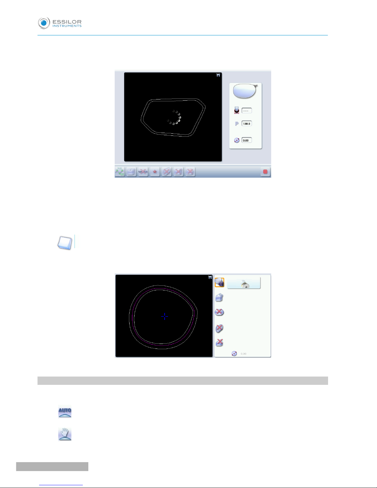
Area definition screen
1. Lock / unlock the area delimitation points
2. Move the area delimitation points
3. Back to the main screen
USER MANUAL> II. EDGING A LENS
59
Pro-E 600_Pro-E 700 > v1 -10.18
Page 60

4. Enable area delimitation on the touch screen
5. Modify the selected value
Legend of colours delimiting the shape areas:
(pink) Bevel finish
(yellow) / (orange) Groove finish (in the case of a Groove - Groove mixed job, the colours make it
possible to differentiate grooves with different parameters)
(black) Flat-edge finish
b. Configuring the mixed finish
Initiating a mixed finish
Call up the desired shape located on the tracer or on the job management program.
The shape is displayed on the edger work screen.
Select lens material.
Press to select mixed job mode.
Select your type of cycle.
Choose whether or not to polish the lens.
You cannot do a chamfer on a mixed job.
For more information on polishing, refer to the section Edging a lens > Polishing (F p.67).
Press .
The door closes, the lens is clamped and then felt.
The mixed finish screen is displayed:
The default setting is the bevel - groove finish in automatic mode.
Customizing the mixed finish
Select the desired type of mixed finish.
Press to access the area definition screen.
>
>
>
>
1
2
3
4
5
6
1
2
Pro-E 600_Pro-E 700 > v1 -10.18
60
USER MANUAL> II. EDGING A LENS
Page 61

The area definition screen is displayed on a 1:1 scale. You can thus refer to a sample lens placed on
the screen.
Select the finish you want in area 1, then area 2.
Press the button to unlock an area delimitation point.
Press the and buttons to move the unlocked point.
Press to move the delimitation points directly on the touch screen. The two points are then
unlocked. Drag them with the stylus.
If necessary, press to modify the position of the center of the groove or bevel using the buttons
and .
This value cannot be modified in automatic mode.
If necessary, press and to modify the groove depth and width using the and
buttons.
Press .
The edging cycle starts.
When the edging cycle is finished, the retouch screen is displayed.
Press to release the lens.
If necessary, retouch the lens.
Otherwise, start edging the second lens. Select the lens directly on the screen, on the left or right of the
work area.
The edging screen for the second lens is displayed. All finishes chosen and the modifications made
are kept.
>
>
>
>
3
4
5
6
7
8
9
10
USER MANUAL> II. EDGING A LENS
61
Pro-E 600_Pro-E 700 > v1 -10.18
Page 62
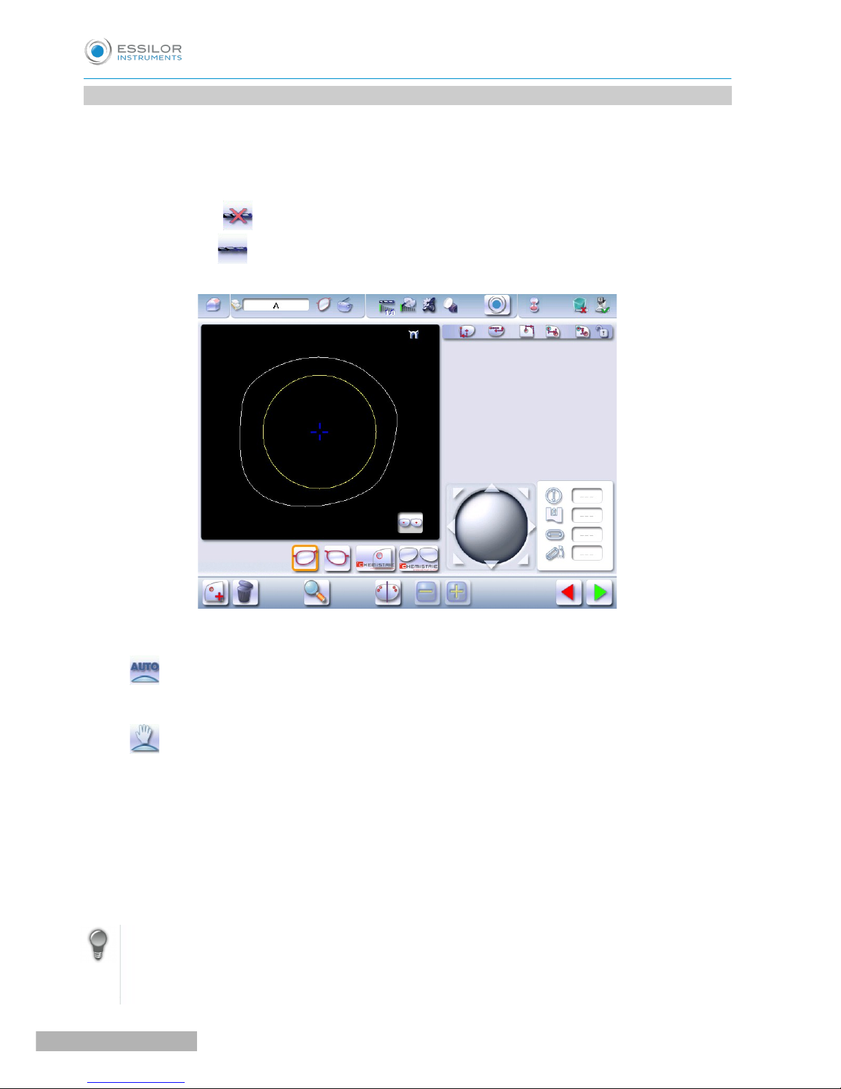
8. PERFORM A DRILLED JOB
You have the option of adding or modifying drillings on a job.
The function can be accessed on the edging screen:
Carry out:
• a short click on (when the job does not show drilling),
• a long click on (when the job already shows drilling).
The following screen will appear:
You can do the drilling in automatic mode or in customized mode:
• In automatic mode (F p.63), you do not have anything to configure. The drilling angle consists of
the average value calculated at right angles with the front surface of the lens for each drilling point.
The lens edging starts automatically after the feeling cycle.
• In customized mode (F p.65), you can do the following:
◦ Drilling at right angles with the front or rear surface: you can modify the diameter but not the
drilling angle which is automatically calculated by the edger based on the lens curve.
◦ Customized drilling: you can modify the diameter and angle for each drilling point.
• You can consult the description of the customized drilling screen (F p.64).
Two different diameter drill bits are available: a 1 mm bit and a 0.8 mm bit. If the diameter of the drilling
point is smaller than that of the installed drill bit, an error message is displayed. Change the drill bit or
modify the diameter of the drilling points.
You can also create various combinations:
• Drilled bevel
• Drilled high-base bevel
Pro-E 600_Pro-E 700 > v1 -10.18
62
USER MANUAL> II. EDGING A LENS
Page 63

• Drilled groove
• Drilled mixed finish
You have the option of adding or modifying drillings on a job.
The function can be accessed on the edging screen:
Carry out:
• a short click on (when the job does not show drilling),
• a long click on (when the job already shows drilling).
The following screen will appear:
For more information, consult the section Preparing a drilled job. (F p.128).
a. Automatic drilling
Call up the desired shape located on the tracer or on the job management program.
The shape is displayed on the edger work screen.
After the tracing of a shape with drilling settings:
• The drilling function is selected by default.
• The automatic mode is selected by default.
Select lens material.
Select the type of finish.
Select the type of cycle.
Choose whether or not to polish and/or chamfer your lens.
>
>
1
2
3
4
5
USER MANUAL> II. EDGING A LENS
63
Pro-E 600_Pro-E 700 > v1 -10.18
Page 64

For more information, consult the section Edging a lens > Perform a polishing (F p.67) and Edging a
lens > Perform a chamfering (F p.67).
Press the “cycle start” button (front face) or .
The door closes, the lens is clamped and then felt.
The edging cycle starts.
When the edging cycle is finished, the retouch screen is displayed.
Press to release the lens.
If necessary, retouch the lens.
Otherwise, start edging the second lens. Select the lens directly on the screen, on the left or right of the
work area.
The edging screen for the second lens is displayed. All finishes chosen and the modifications made
are kept.
b. Legend screen for customized drilling
1. Type of drilling
◦ Perpendicular to the front surface
◦ Perpendicular to the rear surface
◦ Customized
>
>
>
>
6
7
8
Pro-E 600_Pro-E 700 > v1 -10.18
64
USER MANUAL> II. EDGING A LENS
Page 65

2. Select the drilling points
◦ Nasal side
◦ Temporal side
◦ All drilling points
3. Modify the selected value
4. Modify the diameter
◦ Diameter value (mm)
◦ Difference between the initial value and the modified value
5. Modify the drilling angle
◦ Drilling angle value (degrees)
◦ Difference between the initial value and the modified value
6. Cross-sectional view
Cross-sectional view of the lens after the feeling cycle, showing the angle of the drill bit at the selected
drilling point.
7. Reminder of size reduction/increase applied to lens diameter
8. Navigation
◦ Stop the cycle
◦ Return to the main edging screen without saving your changes
◦ Starting the cycle
c. Customized drilling
Call up the desired shape located on the tracer or on the job management program.
The shape is displayed on the edger work screen.
After the tracing of a shape with drilling settings:
• The drilling function is selected by default.
• The automatic mode is selected by default.
Select lens material.
Change the edging mode. Press to select customized mode .
Select the type of cycle.
Choose whether or not to polish and/or chamfer your lens.
>
>
1
2
3
4
5
USER MANUAL> II. EDGING A LENS
65
Pro-E 600_Pro-E 700 > v1 -10.18
Page 66

For more information, consult the section Edging a lens > Perform a polishing and Edging a lens >
Perform a chamfering (F p.67).
Press the “cycle start” button (front face) or .
The feeling cycle starts.
The customized drilling screen is displayed.
Select the type of drilling you want to do.
If necessary, select the drilling point(s) you want to modify.
If necessary, modify the diameter and/or angle of the selected drilling point.
The difference between the initial value and the modified one is displayed in the delta column.
Press .
The edging cycle starts.
When the edging cycle is finished, the retouch screen is displayed.
Press to release the lens.
If necessary, retouch the lens.
Otherwise, start edging the second lens. Select the lens directly on the screen, on the left or right of the
work area.
The edging screen for the second lens is displayed. All finishes chosen and the modifications made
are kept.
>
>
>
>
>
>
6
7
8
9
10
11
12
Pro-E 600_Pro-E 700 > v1 -10.18
66
USER MANUAL> II. EDGING A LENS
Page 67

9. PERFORM A POLISHING
Press the button to activate/deactivate polishing.
LENS MATERIAL AVAILABLE OPTIONS
The polishing option is pre-selected and is strongly recommended by the manufacturer to
prevent small cracks.
Make sure you select the correct type of material for MHI (> 1.5) or Tribrid lenses and never
polish a lens of this type without water. Otherwise, the polishing wheel could suffer irreversible
damage.
The polishing option is pre-selected.
The polishing option is not available for a high-base job. Nevertheless, the wheel was designed to
create an equivalent finish for polycarbonate lenses.
10. CHAMFERING
The chamfer, also called counter-bevel, removes the sharp edge of the lens.
• Standard value of a small chamfer: 0.20 mm
• Standard value of a large chamfer: 0.40 mm
Before you select a type of chamfer, make sure it is compatible with the lens characteristics:
• Lens material
LENS MATERIAL AVAILABLE OPTIONS
The quality of the chamfer depends on the spraying. Make sure there is a constant
flow of water until the end of the chamfering operation.
USER MANUAL> II. EDGING A LENS
67
Pro-E 600_Pro-E 700 > v1 -10.18
Page 68

• Thickness at the edge of the lens
LENS THICKNESS AVAILABLE OPTIONS
> 1.2 mm
between 1 and 1. 2 mm
< 1 mm
• Distance between the edge of the groove and the edge of the lens
DISTANCE AVAILABLE OPTIONS
> 0.8 mm
between 0.5 and 0.8 mm
< 0.5 mm
The chamfers available also depend on the lens shape and the posiblock used when blocking.
Press on the buttons and to configure a small chamfer, a large chamfer or no chamfer on the
front and rear surfaces of the lens.
11. PERFORM A RETOUCHING
Pro-E 600_Pro-E 700 > v1 -10.18
68
USER MANUAL> II. EDGING A LENS
Page 69

1. Diameter modification
2. Manual lens clamping
3. Retouch launch
Differences with the edging screen
The edging screen is different to the retouch
screen through:
• the presence of the posiblock
• no frame thickness
• the “departure cycle” button.
When the first-lens edging cycle is finished:
Press to release the lens.
Proceed to lens assembly and check that edging was correctly configured.
Depending on your job:
• If your job is perfect, proceed with the machining of your second lens.
> All of the selected finishing options and modifications made are kept.
• If the lens requires adjustment, do a retouch on the edged lens to obtain optimal results.
Indicate the size reduction to be applied to the lens you want to retouch.
The chosen finish and the modifications made during the edging cycle are automatically selected.
Insert the lens in the posiblock holder.
To close the clamp shafts manually, do a long press on .
Press .
For a customized finish, the customized finish screen is displayed.
In all other cases, the door closes, the lens is clamped automatically, then the retouching starts.
Select the second lens to be edged directly on screen, on the left or right of the work area.
>
>
>
>
1
2
3
4
5
6
USER MANUAL> II. EDGING A LENS
69
Pro-E 600_Pro-E 700 > v1 -10.18
Page 70

The edging screen for the second lens is displayed.
All finishes chosen and the modifications made are kept. The retouch done on the first lens is
automatically saved for the edging of the second lens.
12. PERFORM A “SUPER CHAMFER” (PRO-E 700)
The “Super Chamfer” is strongly recommended on:
=>a fairly flat frame with weak or negative index lenses, for which the thickness of the lens would prevent
the closing of the arms.
Without the “Super Chamfer” With the “Super Chamfer”
=>a sports or safety frame with weak or negative index lenses, therefore thick at the edge which would
place them closer to the face of the wearer.
Since the bottom part of the lens is not touched by a frame, the objective is to increase the distance in order
to eliminate injury risks.
>
>
Pro-E 600_Pro-E 700 > v1 -10.18
70
USER MANUAL> II. EDGING A LENS
Page 71

Without the “Super Chamfer” With the “Super Chamfer”
The “Super Chamfer” allows you to break the ridge of the lens on the rear surface at a defined distance and
configure it in relation to:
• in the center of the groove.
• at the top of bevel, step bevel .
Press on and select the “Super Chamfer” .
The adjustment field appears on the main screen:
Groove Bevel
Press on and to adjust the distance between the chamfer and the top of the bevel or between the
chamfer and the center of the groove, by taking account of the thickness of the lens.
Distance (mm)
By default: 2.3*
Minimum 1
Maximum 6
Distance (mm)
By default: 2.3*
Minimum 1
Maximum 6
* depends on the frame thickness.
>
1
2
USER MANUAL> II. EDGING A LENS
71
Pro-E 600_Pro-E 700 > v1 -10.18
Page 72

Availability of the “Super Chamfer” by finish
FINISHING WHEEL
Not available
13. PERFORM A CHEMISTRIE TM JOB (PRO-E 700)
is a technical solution that, through a magnet system, allows you to superimpose
a pair of additional “CLIP” lenses on the “ophthalmic” lenses initially mounted on the customers’ frames.
Near vision
Blue light
Solar
3D Vision
a. Prerequisites
You must center and block the lens before placing it in the edger.
It is recommended to start systematically with the edging of the ophthalmic lenses
Prerequisite: the lens must be centered and blocked before placing it in the edger.
Pro-E 600_Pro-E 700 > v1 -10.18
72
USER MANUAL> II. EDGING A LENS
Page 73

b. Preparing a Chemistrie TM job
The Chemistrie screensTMare accessible via the “drilling” menu in the preparation screen for a drilled
job.
For more information, consult the section Preparing a drilled job. (F p.128).
Carry out:
• a short click on (when the job does not show drilling),
• a long click on (when the job already shows drilling).
The following screen will appear:
• Press to position the magnet and outline its shape.
• Press to visualize the binocular view.
The settings of a Chemistrie jobTMbe performed in two steps:
1. Positioning and settings of the magnets on the ophthalmic lenses.
2. Positioning and settings of the magnets on the Chemistrie clipsTM (several types of Chemistrie jobs
TM
are possible for only one job)
Ophthalmic lens
Press to position the magnet and outline its shape.
1/ At the first mount, the shape of the magnet is square:
1
USER MANUAL> II. EDGING A LENS
73
Pro-E 600_Pro-E 700 > v1 -10.18
Page 74

The button changes .
2/ At the second mount, the shape of the magnet becomes round:
The button changes .
Press for a few seconds on the setting value to be modified according to the selected shape:
Square Circle
Height Diameter
Depth Depth
Width
2
Pro-E 600_Pro-E 700 > v1 -10.18
74
USER MANUAL> II. EDGING A LENS
Page 75

The numeric keypad is displayed.
You can also use the or buttons to decrease or increase the selected value.
Press to access the binocular view.
The following screen will appear:
Press to confirm the job.
Chemistrie TM (clip) lenses
Press to configure the Chemistrie lensTM".
The following screen will appear:
>
>
>
3
4
1
USER MANUAL> II. EDGING A LENS
75
Pro-E 600_Pro-E 700 > v1 -10.18
Page 76

Press to select the Chemistrie clipTM “SUN”.
The clip is selected:
The tool bar appears:
Press to configure the size increase (or size decrease=> less frequent) applied to the shape of
the ophthalmic lens to configure the shape of the Chemistrie lensTM.
Press a few seconds on the setting to be modified:
=> the numeric keypad is displayed.
You can also use the or buttons to decrease or increase the selected value.
Press to configure the width of the bridge
Press a few seconds on the setting to be modified:
=> the numeric keypad is displayed.
You can also use the or buttons to decrease or increase the selected value.
Press to configure the height of the bridge.
Press a few seconds on the setting to be modified:
=> the numeric keypad is displayed.
You can also use the or buttons to decrease or increase the selected value.
Pres to configure the difference in positioning between the magnets of the ophthalmic lens and
those of the Chemistrie clipTM.
Press a few seconds on the setting to be modified:
=> the numeric keypad is displayed.
You can also use the or buttons to decrease or increase the selected value.
>
>
2
3
4
5
6
Pro-E 600_Pro-E 700 > v1 -10.18
76
USER MANUAL> II. EDGING A LENS
Page 77

Your job has been configured.
You can prepare other Chemistrie jobsTM if necessary , , .
Press to validate the Chemistrie jobTM.
c. Prepare the Chemistrie TM lenses
This procedure is valid for the clips, , , .
=> the clips must be prepared in the same way as a classical lens.
Position the two lenses as indicated and apply light pressure in the opposite direction of the curve of the
lenses to clip them together.
Ensure that the size of the Chemistrie lensTM is appropriate.
Check visually that the lens can accommodate the shape.
>
7
1
2
USER MANUAL> II. EDGING A LENS
77
Pro-E 600_Pro-E 700 > v1 -10.18
Page 78

For more precision, you can verify it using the tracer, by using the centering function.
Position the posiblock in the center of the lens.
The lenses are ready to be edged
d. Cut a Chemistrie lens
Press to call up the desired shape located on the tracer.
The shape is displayed on the edger work screen with the selected clips:
Press on to select the ophthalmic lenses: .
Configure edging:
1. Select lens material.
2. Select the type of cycle.
3. Select the finish,
4. Choose whether or not to polish and/or chamfer your lens.
>
>
3
2
3
Pro-E 600_Pro-E 700 > v1 -10.18
78
USER MANUAL> II. EDGING A LENS
1
Page 79

Place the lens in the posiblock holder.
Place the metal peg of the posiblock upwards and the positioner downwards: a magnet is used to
hold the lens in position on the axis.
You can clamp the lens manually by pressing .
Make sure you move your hand well away before you start the edging cycle.
Press to start the cycle.
Proceed to a retouch if necessary, then carry out the edging of the second lens.
> With the ophthalmic lenses now edged, carry out the edging of the Chemistrie lenses TM.
Select the Chemistrie clipTMthat you wish to edge.
The following screen is displayed:
>
4
5
6
7
USER MANUAL> II. EDGING A LENS
79
Pro-E 600_Pro-E 700 > v1 -10.18
Page 80

Place the two lenses (prepared beforehand) in the posiblock holder.
Place the metal peg of the posiblock upwards and the positioner downwards: a magnet is used to
hold the lens in position on the axis.
You can clamp the lens manually by pressing .
Make sure you move your hand well away before you start the edging cycle.
Check that the Chemistrie lensesTM are still properly in place during the clamping phase. They must
remain clipped together.
Configure edging:
For the clips and , by default, edging is configured as follows:
Material
Finishing wheel
Edging mode
Type of cycle
Polishing
8
9
Pro-E 600_Pro-E 700 > v1 -10.18
80
USER MANUAL> II. EDGING A LENS
Page 81
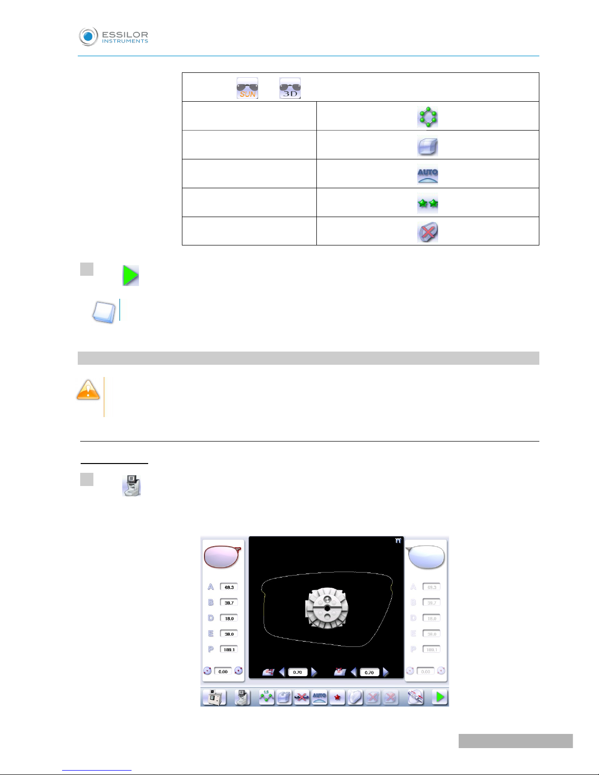
For the clips and , by default, edging is configured as follows:
Material
Finishing wheel
Edging mode
Type of cycle
Polishing
Press to start the cycle.
Re-start the procedure for as many times as you have Chemistrie clipsTM to perform.
14. CARRY OUT A HALF JACKET JOB (PRO-E 700)
We highly recommend that you edge a test lens before carrying out the edging of the final lens.
Preferably use a test lens that has a base unit equivalent to the ophthalmic lens.
a. Outline the step bevel trajectory on a Half Jacket shape
Call up the form
Press to call up the desired shape located on the tracer.
The shape is displayed on the edger work screen.
>
10
1
USER MANUAL> II. EDGING A LENS
81
Pro-E 600_Pro-E 700 > v1 -10.18
Page 82

Press to select the Half Jacket finish.
Select lens material.
The cycle is automatically configured in “Customized”.
Choose to perform a “super chamfer” on the rear surface of the lens.
It is strongly recommended to perform a “Super Chamfer” as part of a “Half Jacket” job.
For more information, consult the section Edging a lens > Perform a polishing and Edging a lens >
Perform a Pro-E 700 super chamfer (F p.70).
Press .
The door closes, the lens is clamped and then felt.
The step bevel finishing screen is displayed by default.
Press on to create step bevel shelf bevel, Half Jacket specific.
The following screen will appear:
>
>
>
2
3
4
5
6
Pro-E 600_Pro-E 700 > v1 -10.18
82
USER MANUAL> II. EDGING A LENS
Page 83

1. Front surface tracking step bevel screen
2. Work area
Image of the shape to be edged
3. Access to step bevel definition screen
4. Zoom window
Represents the bevel profile at the position of the cursor.
5. Width of the flat side of the bevel
The value of the flat side of the bevel must be between 0.4 mm and 2 mm.
6. Front surface tracking value
The value of front surface tracking must be between 0 mm and 1.3 mm. This value is definable only in
the “front surface tracking” screen.
7. Lens base
8. Frame base
9. Reminder of size reduction/increase applied to lens diameter
10. Bevel Base_Range of values of the lens base necessary for the frame
If the lens base used is out of range: the range values are shown in red.
11. Window showing the bevel trajectory on the lens section
Centre of the flat side of the bevel
Front surface/rear surface of lens
12. Number of shelf bevel values
USER MANUAL> II. EDGING A LENS
83
Pro-E 600_Pro-E 700 > v1 -10.18
Page 84

Transition from 4 to 8 shelf bevel values.
Transition from 8 to 4 shelf bevel values.
Transition into free shelf-bevel creation mode (Half Jacket specific)
13. Navigation
◦ Stop the cycle
◦ Back to the main edging screen
◦ Start the edging cycle
Set the step bevel trajectory
Captioned screen
From the customized screen for the step outline, press , then next to access the step bevel outline
screen. The following screen appears:
1. Display and shape work zone
2. Scale 1 shape display window.
3. Tool bar
: Selection of the shelf bevel area for modification.
When the form is selected:
◦ the button changes: ,
◦ the “non-machinable” zone appears in red ( ) on the screen.
Pro-E 600_Pro-E 700 > v1 -10.18
84
USER MANUAL> II. EDGING A LENS
Page 85

: Addition of points to outline the shelf bevel trajectory.
> When the button is selected, it changes:
: Deletion of points to outline the shelf bevel trajectory.
> When the button is selected, it changes:
To add or remove points, the shape must be selected beforehand.
Use the stylus to set the bevel trajectory with precision.
Once the points are set, they appear in blue ( ).
: Front zoom
: Back zoom
: Cancel the preceding action
: Repeat the preceding action.
: Confirm
: Cancel
USER MANUAL> II. EDGING A LENS
85
Pro-E 600_Pro-E 700 > v1 -10.18
Page 86

Create the step bevel trajectory
From the customized screen for the step outline, press to select the shape, then to add
points.
The following screen will appear:
Press and hold the stylus to set the first point of the step bevel trajectory.
An audible signal informs you that the first point is registered.
The point is displayed in blue within the work space and in the display window on scale 1.
Press and hold the stylus to set the second point of the step bevel trajectory.
A green segment ( ) is created between the points.
>
>
>
>
1
2
3
Pro-E 600_Pro-E 700 > v1 -10.18
86
USER MANUAL> II. EDGING A LENS
Page 87

An audible signal informs you that the second point is registered.
The segment is displayed in blue within the work space and in the display window on scale 1.
If you raise the stylus, the bevel curve is displayed in green, it is calculated automatically.
You can redo this trajectory by setting the third point using the stylus.
>
>
USER MANUAL> II. EDGING A LENS
87
Pro-E 600_Pro-E 700 > v1 -10.18
Page 88

Press and hold with the stylus to set the other points of the step bevel trajectory, one after the other.
With each audible signal, raise the stylus a few seconds before setting a new point by pressing and
holding
It is preferable to create a greater number of points at the angles to gain precision, if you wish to
adjust more precisely the bevel trajectory using the zoom.
Conversely, for easier handling, it is preferable to reduce the number of points on the curves so
the adjustment is more effective.
The step bevel trajectory is set.
The orange trajectory () cannot be performed, because the tool cannot reach it.
The trajectory in green ( ) will be performed (it is not necessary to modify the trajectory).
For more information, consult the Set step bevel section > Adjust the trajectory (F p.91)
Go into zoom mode
You can zoom in on a specific point or outline an area.
>
4
Pro-E 600_Pro-E 700 > v1 -10.18
88
USER MANUAL> II. EDGING A LENS
Page 89

Increase a particular point
Press to switch into Zoom mode.
Press and hold the stylus on the point of the shape that you want to see more precisely.
Press on the Frame shape at bottom of groove in white ( ).
An audible signal informs you that the information is registered.
The image is displayed:
1. Locate the form on scale 1.
2. Movement arrow
Movement to the top of the shape
Movement to the bottom of the shape
Press again to enlarge the area.
>
1
2
3
USER MANUAL> II. EDGING A LENS
89
Pro-E 600_Pro-E 700 > v1 -10.18
Page 90

When the enlargement is at a maximum, the icon is grayed .
Press again to shrink the area.
Enlarge a defined area
Press to switch into Zoom mode.
Using the stylus press on a point of the shape.
Move the stylus over the shape.
The defined segment appears in yellow.
Press and hold to set the end of the segment outlining the area that you want to enlarge.
An audible signal sounds 3 times.
>
>
4
1
2
3
4
Pro-E 600_Pro-E 700 > v1 -10.18
90
USER MANUAL> II. EDGING A LENS
Page 91
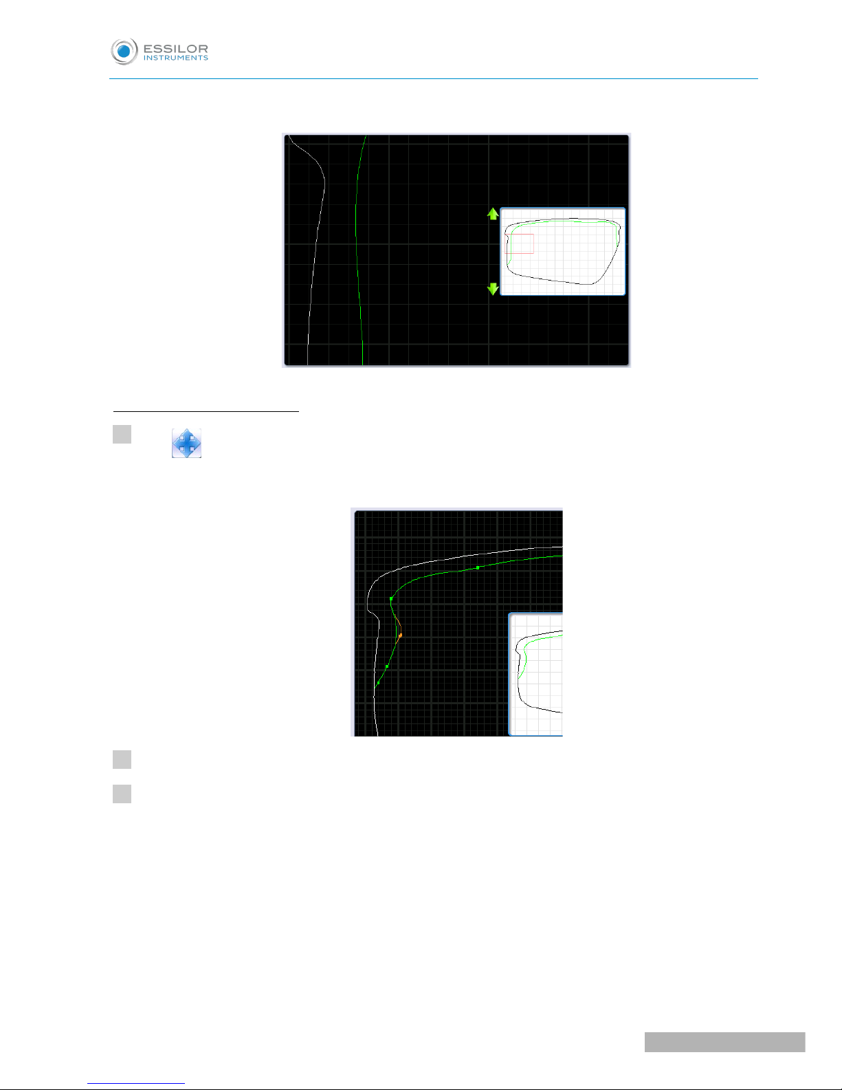
The area is displayed:
Adjust the step bevel trajectory
Press to select the shape:
The points of reference appear, the shape can be modified.
Using the stylus press on a point of the shape.
Move the stylus over the shape.
>
>
1
2
3
USER MANUAL> II. EDGING A LENS
91
Pro-E 600_Pro-E 700 > v1 -10.18
Page 92

The defined segment appears in yellow.
Press and hold the stylus to set the end of the segment.
An audible signal sounds 3 times.
The segment appears in green.
Move the segment using the stylus.
When the trajectory passes by the closed area:
• The segment concerned becomes red.
• The whole bevel curve becomes red in the display window on scale 1.
>
>
4
5
Pro-E 600_Pro-E 700 > v1 -10.18
92
USER MANUAL> II. EDGING A LENS
Page 93

Raise the stylus to validate the modification.
An audible signal sounds 3 times.
The segment becomes blue (only the points of reference set by you will appear), the machine
recalculates the trajectory of the curve => the trajectory becomes green.
The modification is validated.
The modification is validated.
The tracking distance for the front surface of the step bevel is managed in the customized
settings screen for the step bevel in “front surface tracking” mode.
>
>
>
6
USER MANUAL> II. EDGING A LENS
93
Pro-E 600_Pro-E 700 > v1 -10.18
Page 94

Press to confirm the shelf bevel.
b. Finalize the step bevel settings in “front surface follow-up” mode
Configure the flat side of the bevel and the front shelf bevel of the bevel step.
Press the buttons and on the right of your screen to modify the width of the flat side of the bevel.
The result can be viewed in the zoom window.
Press the buttons and on the right of your screen to modify the value of front surface tracking.
It is advised to set the value at 0 because front shelf bevel will be viewable on the entire contour
of the shape.
>
7
1
2
3
Pro-E 600_Pro-E 700 > v1 -10.18
94
USER MANUAL> II. EDGING A LENS
Page 95

The result can be viewed in the zoom window and the display window of the bevel trajectory on the
lens section.
Press systematically to tilt of the bevel (mounting aid).
The bevel tilt is selected .
The result can be viewed in the zoom window.
Press the “cycle start” button (front face) or .
The edging cycle starts.
When the edging cycle is finished, the retouch screen is displayed.
Press to release the lens.
If necessary, retouch the lens.
Otherwise, start edging the second lens. Select the lens directly on the screen, on the left or right of the
work area.
>
>
>
>
>
4
5
6
7
USER MANUAL> II. EDGING A LENS
95
Pro-E 600_Pro-E 700 > v1 -10.18
Page 96

The edging screen for the second lens is displayed. All finishes chosen and the modifications made
are kept.
If the test is not mounted correctly in the frame, go to Essibox to modify the shape.
c. Modify the shape on Essibox
If the test lens cannot be mounted, we advise you to modify the shape on Essibox.
Contact your customer support if the job is not available in the job manager on Essibox.
In the job manager screen on Essibox, press the “ID number” to select the job.
The following screen is displayed:
>
>
1
Pro-E 600_Pro-E 700 > v1 -10.18
96
USER MANUAL> II. EDGING A LENS
Page 97

You can visualize the job by pressing .
Adjust the display to a scale of 1 to superimpose the demo lens on the shape.
Press to return to the “M’Eye Touch” creative modification screen.
The following screen is displayed:
>
2
USER MANUAL> II. EDGING A LENS
97
Pro-E 600_Pro-E 700 > v1 -10.18
Page 98

Press to select the point from which you wish to modify the shape
Press to select the “angle” tool
: Reference point: point from which the shape modification will be started.
: Check-points: points allowing you to modify the curve.
Modify the shape to ensure optimal mounting in the Half Jacket frame.
Press to check the shape’s feasibility.
The button becomes red .
The following screen will appear: The shape is valid.
>
3
4
5
6
Pro-E 600_Pro-E 700 > v1 -10.18
98
USER MANUAL> II. EDGING A LENS
Page 99

• Large wheels
• Drill bit
Press to confirm the new shape.
Recall the shape on the edger to make a new test lens.
7
8
USER MANUAL> II. EDGING A LENS
99
Pro-E 600_Pro-E 700 > v1 -10.18
Page 100

15. M’EYE SIGN FEATURE (PRO-E 700)
This section describes the procedures relating to performing an engraving:
• the choice of engraving and preparation of engraving on Essibox (or on a networked computer),
(F p.100)
• the completion of the engraving on the edger, (F p.112)
• setting up favorites. (F p.116)
a. To prepare the engraving
The preparation of engraving is carried out on Essibox (or a networked computer) in two stages:
1. choosing the motif, (F p.100)
2. setting up the engraving (F p.108)
Choosing the motif
Various work options are possible, you can:
• choose a motif to be engraved without prior job and shape preparation.
>This option lets you save a selection of motifs simply and quickly for engraving later.
• choose a motif to be engraved after having prepared the job and the shape.
>This option allows you to show the customer the position and the size of engraving on the shape.
Menu screen
Choice of motif
Pro-E 600_Pro-E 700 > v1 -10.18
100
USER MANUAL> II. EDGING A LENS
 Loading...