

Page 1

User Manual
Page 2

CONTENTS
INTRODUCTION 5
I. FIRST STEPS WITH PRO-E 600 7
1. Descriptive diagrams 8
2. Using the edger 10
a. Turning on the edger 10
b. Switching off the edger 10
c. Using the touch screen and keypads 11
d. Edging screen 12
II. EDGING A LENS 15
1. Edger working environment 16
a. Menu screen 16
b. Calling up a shape 18
c. Lens set-up and feeling 19
2. Perform a Beveling 21
a. Automatic beveling 21
b. Legend screen for customized bevels 23
c. Customized beveling 24
d. Modifying the bevel curve 26
e. Modifying the bevel curve at a particular point 27
f. Displacing the bevel curve 28
3. High-base beveling 28
a. Captioned screens 29
b. High-base beveling 31
4. Perform a Step bevel 36
a. Install the step bevel tool 37
b. Captioned screens 41
c. Perform a Step bevel 42
5. Grooving 48
a. Automatic grooving 49
b. Customized groove legend screen 50
c. Customized grooving 51
d. Modifying the groove curve 53
e. Modifying a point in the groove curve 54
f. Displacement of the groove curve 55
6. Produce a Flat-edge finish 56
7. Do a mixed job 57
a. Legend screens 57
b. Configuring the mixed finish 59
8. Perform a Drilled job 61
a. Automatic drilling 62
b. Legend screen for customized drilling 63
c. Customized drilling 64
9. Perform a Polishing 65
10. Chamfering 66
USER MANUAL> CONTENTS
Page 3

11. Perform a Retouching 67
III. CONFIGURING THE EDGER 69
1. Configure the edger 70
a. Time, date and language 70
b. Connections 71
c. Screensaver 72
2. Adjusting the precision of the edger 72
a. Adjusting the diameter of the finished lenses 72
b. Adjusting the position of the bevel and groove 73
c. Adjusting the diameter of drill-holes 74
d. Adjusting the chamfer 75
e. Adjusting the groove 76
f. Adjust the position of high-base bevel 77
g. Adjust the position of the step bevel 78
IV. MAINTENANCE & SERVICING 81
1. Carrying out the autotests 82
2. Calibrating the touch screen 83
3. Consulting the preventive maintenance screen of the “small tools” modul 84
4. Changing or cleaning the edger tools 86
a. Changing or cleaning the drill bit 87
b. Changing or cleaning the mill bit 91
c. Changing the Step bevel wheel 94
d. Changing the chamfering wheel 97
5. Statistics and technical log 100
a. Edger cycles 100
b. Technical log and errors 101
6. Maintaining and cleaning the edger 102
a. Precautions required 102
b. Clean the door, the “small tools” module and the wheels 103
c. Dressing the wheels 104
TECHNICAL DATA 107
1. Edger 108
2. Environment 109
GENERAL INFORMATION 111
1. Symbols 112
2. Modifications 112
3. Declaration of conformity 113
4. Copyright 113
5. Materials and products 113
6. Safety instructions: 113
7. Electromagnetic waves 114
GLOSSARY 115
USER MANUAL> CONTENTS
Page 4

INTRODUCTION
To take full advantage of the functions on you Pro-E 600 edger, we encourage you to consult the entire
manual.
You need to have at least memory version: V 1.0.0
USER MANUAL> INTRODUCTION
5
Pro-E 600 > v1 -02.17
Page 5

I. FIRST STEPS WITH PRO-E 600
Page 6
This chapter contains all the information relating to the first use of the edger:
• Description of the edger (F p.8)
• Using the device (F p.10)
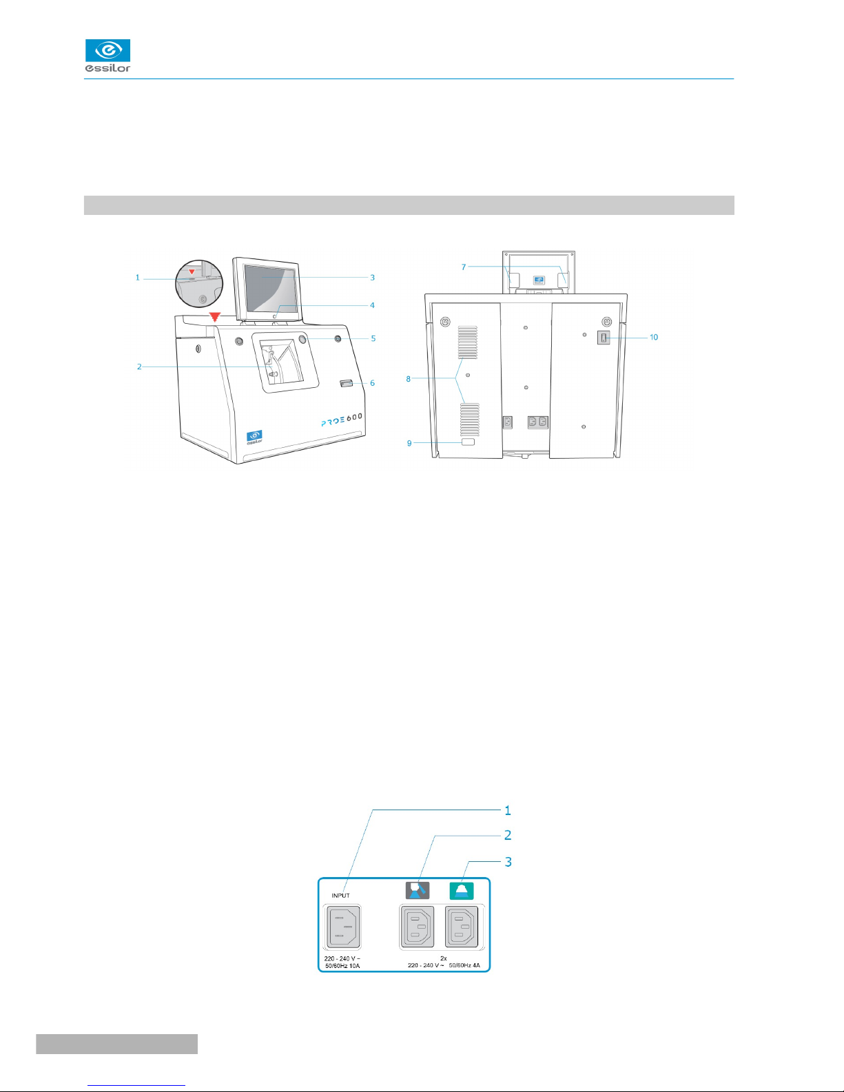
1. DESCRIPTIVE DIAGRAMS
This section consists of descriptions and lists of accessories.
1. USB plug
2. Trough
3. Screen
4. ON/OFF button
5. Cycle start button
6. Barcode reader
7. Screen tilt buttons
8. Fans
9. Manufacturer plate
10. Main switch
Connectors
Pro-E 600 > v1 -02.17
8
USER MANUAL> I. FIRST STEPS WITH PRO-E 600
Page 7

1. Power socket
2. Solenoid valve socket
3. Pump socket (tank + pump) / Solenoid valve socket (town)
Accessories
Stylus
Posiblock removal pliers
Triangular key
White dressing stone for finishing wheel
Square dressing stone for polishing wheel
Transport wedges to be kept
Accessory box
- Usage :
• 22 mm posiblock holder
• 18 x 14 mm posiblock holder
• 22 mm stop
• 18 x 14 mm stop
• Mill/drill bit replacement tool (blocking key)
• Ø 1.0 mm drill bit (quantity 2, including one mounted on the module)
• Ø 0.8 mm drill bit
• Ø 1.5 mm edging mill bit (quantity 2, including one mounted on the module)
• Ø 20 mm grooving wheel (mounted on the module)
• Chamfering wheel (mounted on the module)
• Step bevel wheel
- Maintenance
• Blocking key for tool changes (drill bit/mill bit)
• Adjustable wrench for tool changes (drill bit/mill bit)
• Accessory for Step bevel wheel assembly/dismantling
• Adjustable wrench for tool changes (drill bit, mill bit, chamfering wheel)
Options
• Open or closed circuit spraying kit
• Milling chip recovery tray
• Posiblock holder and “Weco” posiblock stop” accessory kit
• M’Eye Sign Box
Connection accessories
• 220 V power cable
• RJ45 cable for the tracer-edger connection
• Essibox connection cable
• Wastewater evacuation pipe with attachment ring
• 2 connectors to clip onto two internal water pipes and connect to the rinsing kit
USER MANUAL> I. FIRST STEPS WITH PRO-E 600
9
Pro-E 600 > v1 -02.17
Page 8
2. USING THE EDGER
In this section, you will find all the information concerning the following:
• Turning on (F p.10) andoff (F p.10) the edger,
• the use of the touch screen and the keyboards (F p.11),
• the description of the work screens of the edger (F p.12).
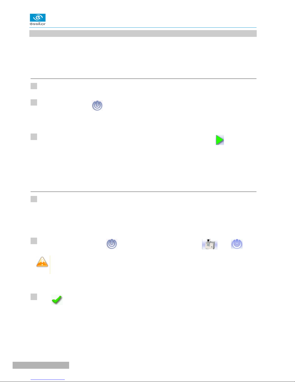
a. Turning on the edger
Press the main switch, located behind the edger on the left, to power it up.
Press the ON/OFF button located under the touch screen.
The edger will initialise.
On the edger screen, press on the “cycle start” button on the front surface or on the icon to end the
initialization phase.
A beep indicates that the initialisation was successful.
The edger is ready for use when the initial screen is displayed.
b. Switching off the edger
Before switching off the edger:
• Check that there is no glass in the trough
• Check that the lens clamp shafts are loosened and that the trough door is open
• Select the edging screen
Briefly press the ON/OFF button located under the touch screen or press , then .
Do not press the ON/OFF button for several seconds. This would result in a shut-down of the
machine and a warningmessage would be displayed at the next switch-on.
A confirmation message is displayed on the screen.
Press to confirm.
The edger will switch off.
>
>
>
>
1
2
3
1
2
3
Pro-E 600 > v1 -02.17
10
USER MANUAL> I. FIRST STEPS WITH PRO-E 600
Page 9
Extended period of non-use
For a prolonged period of non-use (a few days), it is preferable to turn off the edger using the main
switch.
It must be powered off at least once a week.
c. Using the touch screen and keypads
Using the touch screen
Use the stylus supplied with the machine to use with the touch screen.
You can also touch the screen with your finger.
• If the screen is not sensitive enough to finger pressure, press lightly with a fingernail.
• If the response area does not correspond to the position of the key, you need to calibrate the touch
screen. For further information, refer to the section Maintenance and servicing > Check and calibrate
> Calibrate the touch screen (F p.83).
• Never press hard on the screen as this could break it.
• Never press on the screen with sharp objects such as pens, scissors, clamps, etc.
• Screen breakage is not covered by the guarantee.
On the screen, press the icon buttons to access the desired menus and job functions .
Using the keypads
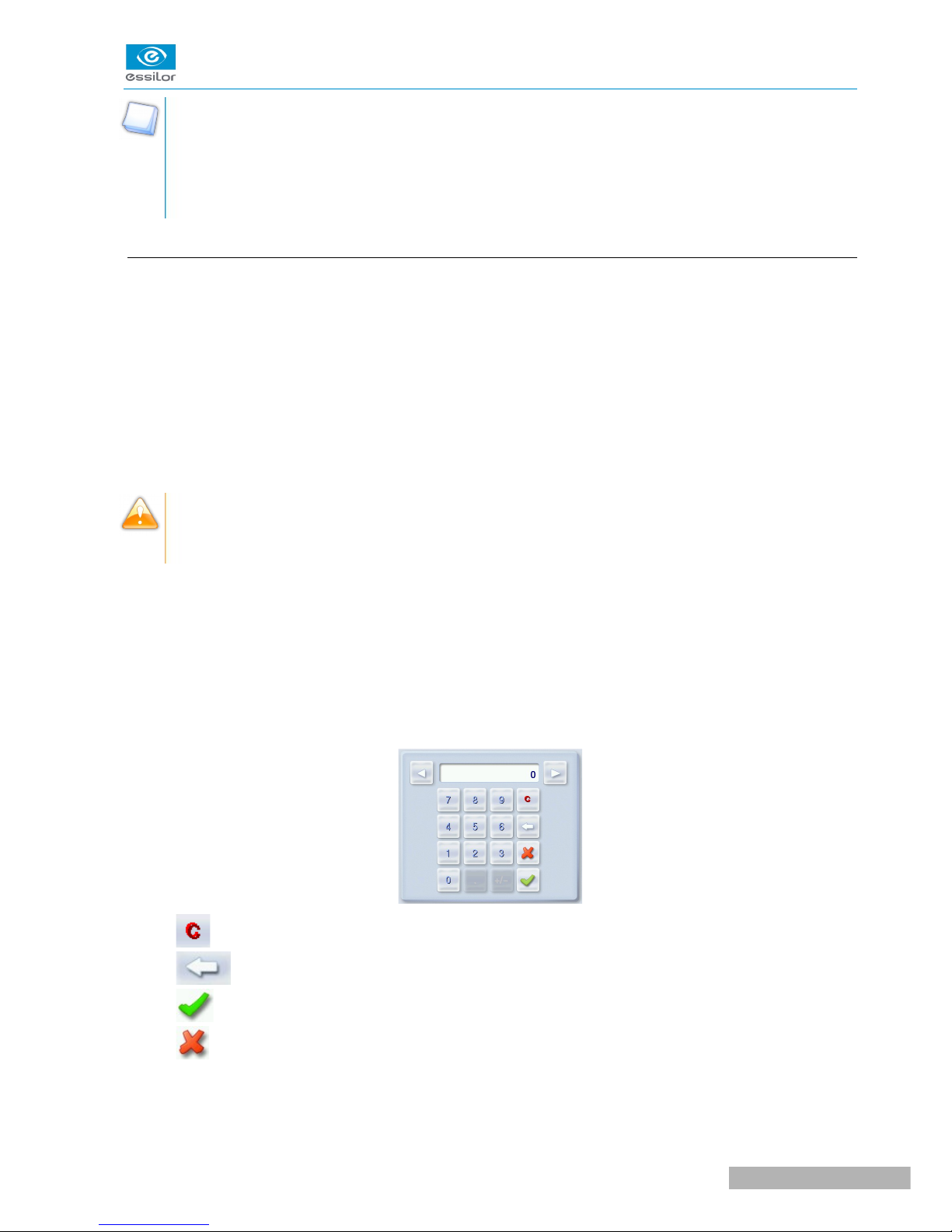
When you need to enter or modify data, two types of keypads are automatically displayed, according to the
information to be entered.
• The numeric keypad is displayed for entering values.
• Reset the fields
• Go back
• Confirm
• Cancel and go back to the work screen
• The alphanumeric keypad is displayed to save or search for jobs.
USER MANUAL> I. FIRST STEPS WITH PRO-E 600
11
Pro-E 600 > v1 -02.17
Page 10
• Job ID
• Job reference (alphanumeric characters)
• Job list
&
• Collection list (when the edger is connected to a Essilor range tracer)
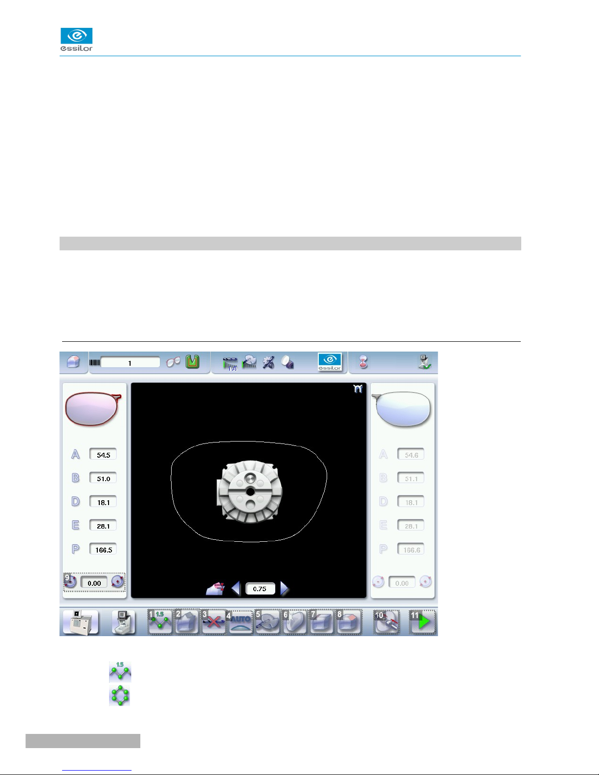
d. Edging screen
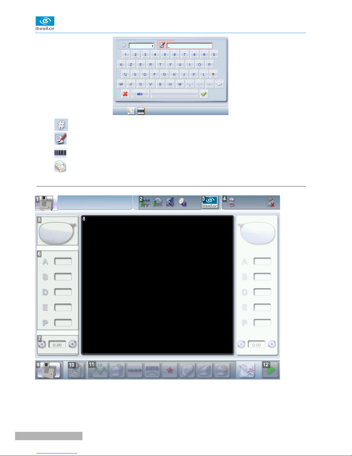
1. Work screen indicator
2. Tool wear indicators
3. Settings
Pro-E 600 > v1 -02.17
12
USER MANUAL> I. FIRST STEPS WITH PRO-E 600
Page 11

4. Devices connected
5. Active eye
6. Information on the shape
7. Size increase/reduction
8. Work area
9. Turning off the product/edging screen
10. Job call: Tracer menu
11. Actions available for the current screen
12. Start the edging cycle
Detailed functions
For more information, consult the section Edging a lens > Work environment of the edger > Captioned
screen. (F p.16)
USER MANUAL> I. FIRST STEPS WITH PRO-E 600
13
Pro-E 600 > v1 -02.17
Page 12

II. EDGING A LENS
Page 13
This chapter describes the work environment of the edger and the procedures for edging any type of lens:
• Edger working environment (F p.16)
• Perform a Beveling (F p.21)
• Beveling for a high-base frame (F p.28)
• Produce a step bevel for a high-base frame of a sporting type or a safety frame, (F p.36)
• Grooving (F p.48)
• Produce a Flat-edge finish (F p.57)
• Do a mixed job (F p.57)
• Perform a Drilled job (F p.61)
• Perform a Polishing (F p.65)
• Perform a Chamfering (F p.66)
• Perform a Retouching (F p.67)
1. EDGER WORKING ENVIRONMENT
This section describes the edger working environment and the initial stages of the edging of a lens.
• Description of the edging screen (F p.16)
• Shape call-up procedure (F p.18)
• Putting the lens in place (F p.19)
a. Menu screen
1. Lens material
◦ Plastic lens -index 1.5
&
◦ Polycarbonate lens
Pro-E 600 > v1 -02.17
16
USER MANUAL> II. EDGING A LENS
Page 14
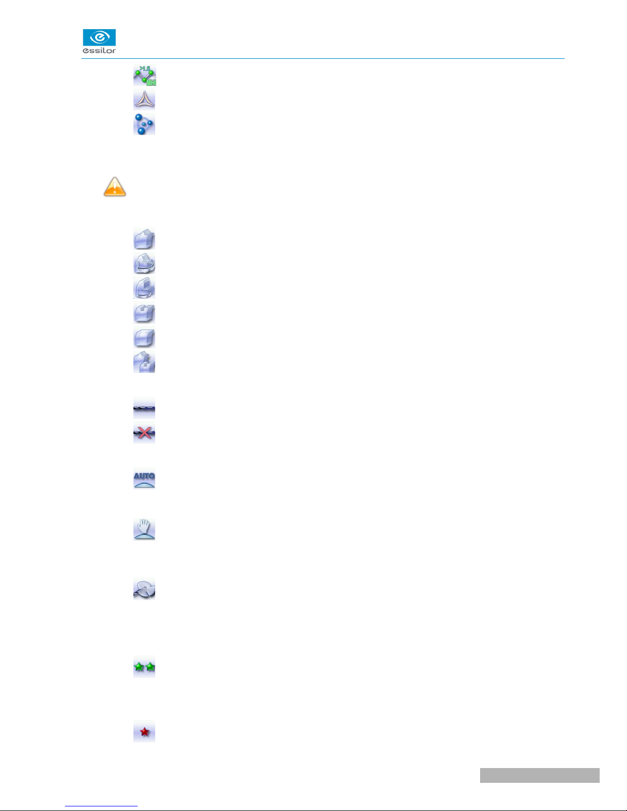
◦ Medium or high index plastic lens - index > 1.5
◦ Trivex lens
TM
◦ Tribrid lens
TM
The configuration of the edging cycles depends on the type of material. An incorrect choice may result in
material damage.
The Pro-E 600 edger does not edge glass lenses.
2. Type of finish
◦ Bevel
◦ High-base bevel
◦ Step bevel
◦ Groove
◦ Flat-edge finish
◦ Mixed job
3. Drilling
◦ Drilling enabled
◦ Drilling disabled
4. Edging mode
◦ Automatic mode
The finish parameters are automatically calculated according to the information acquired when
tracing the frame and feeling the lens.
◦ Customized mode
The finish settings can be fully customized.
5. Type of cycle
◦ Milling cycle
This cycle is recommended for lenses with a hydrophobic coating. It works with all types of
materials. Milling involves a specific feeling cycle: the edger will feel the contour of the shape to
be edged twice, then four feeling operations will be required every 90° to define the segments to
be cut.
◦ 2 stars Cycle
For all types of material. This cycle offers a more sophisticated edging mode than the standard
cycle, dedicated to thin lenses or to hydrophobic lenses when milling is not possible (lens too
quick for example).
◦ Standard cycle
USER MANUAL> II. EDGING A LENS
17
Pro-E 600 > v1 -02.17
Page 15
For all types of material.
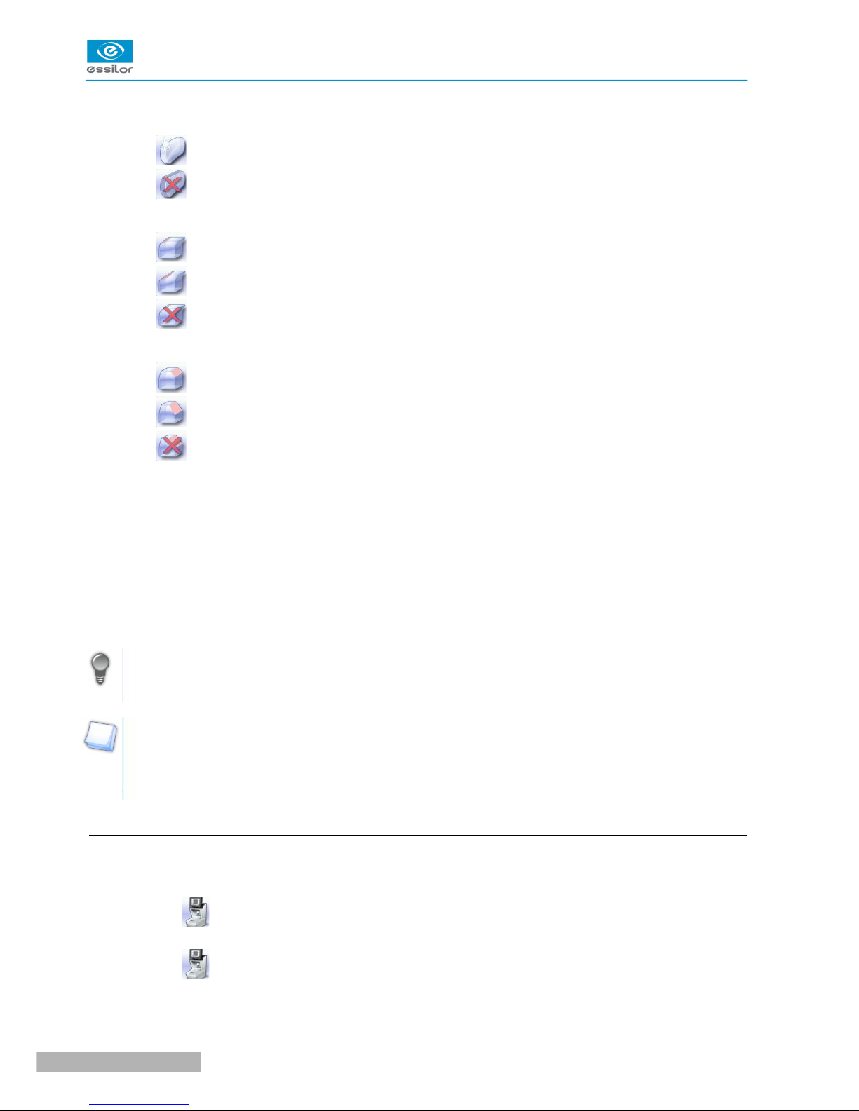
6. Polishing
◦ Polished lens
◦ Non-polished lens
7. Front surface chamfering
◦ Small chamfer
◦ Large chamfer
◦ No chamfering
8. Rear surface chamfering
◦ Small chamfer
◦ Large chamfer
◦ No chamfering
9. Size reduction/increase (mm)
10. Manual lens clamping
Press and hold to close the lens clamp shafts manually.
11. Start the edging cycle
The door closing and lens clamping are automatic.
Function also available via the “cycle start” button on the front surface.
Always browse from left to right: depending on your selection, certain menus will be available while
others will not.
Your habits taken into account
The edger memorises your working habits: as time goes by, the buttons of the functions you use most
often will be displayed by default.
b. Calling up a shape
There are 3 ways of calling up the shape you want to edge:
• Calling up the current job:
> Press to display the shape being processed on the tracer.
• Calling up the number of a shape saved on the tracer:
> Press for a few seconds to open the numeric keypad.
> You can then call up a shape via the ID allocated to it.
• Job call via a barcode:
Pro-E 600 > v1 -02.17
18
USER MANUAL> II. EDGING A LENS
Page 16
> Scan the barcode using the barcode reader (optional).
Always lock down your 2 lenses before proceeding with the edging. If a job in the course of modification on
the tracer (display of the symbol beside the reference) is called up on the edger, a warning message is
displayed.
> Press to continue and display the job on the edger. The modifications underway are then ignored.
> Press to prevent the display of the job and finish the modifications underway on the tracer.
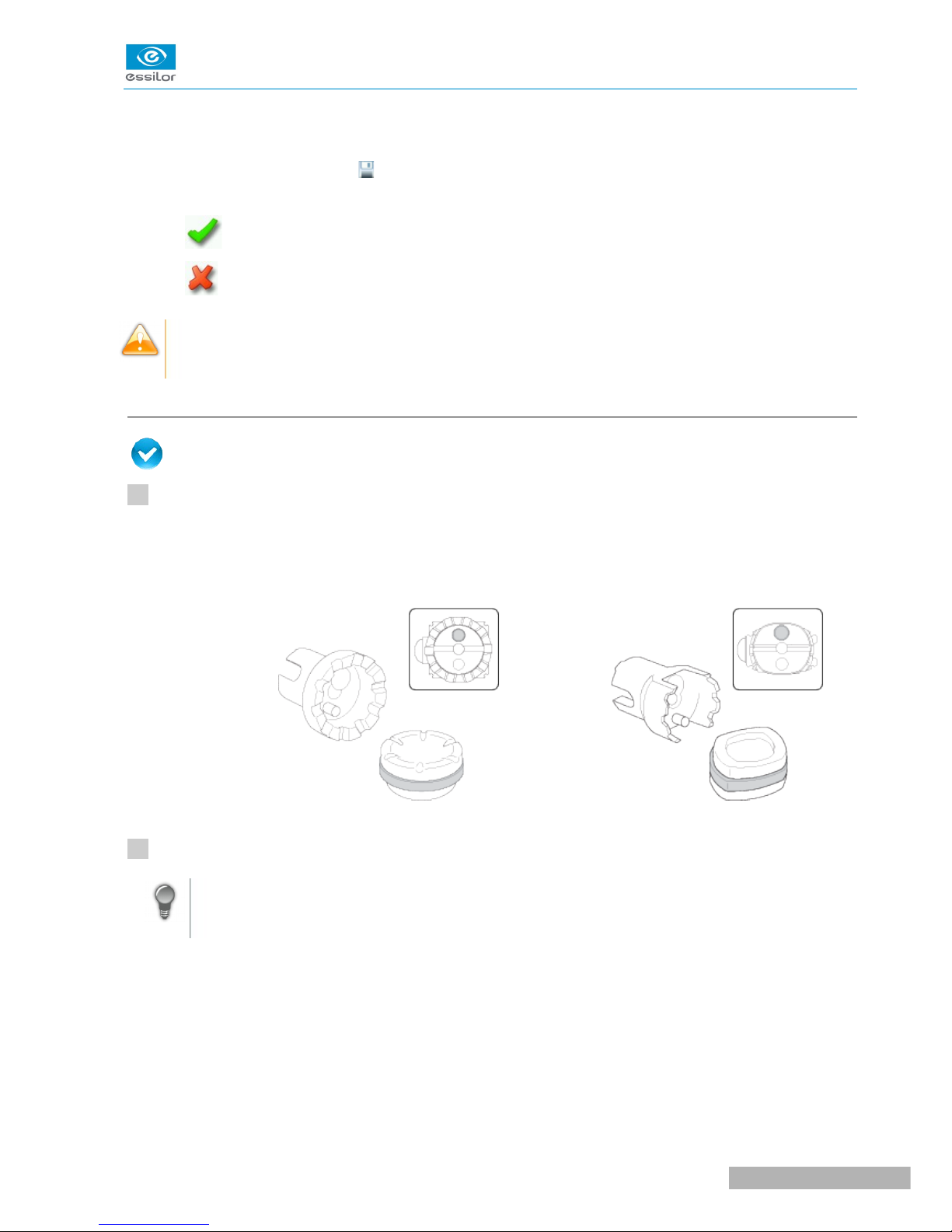
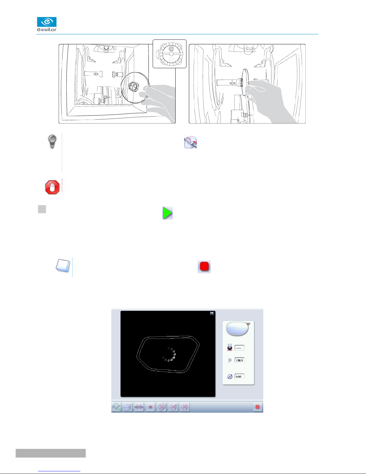
A reminder of the type of posiblock required is displayed on the shape. It is crucial to use the proper
accessory to edge the lens. Otherwise, an error message is displayed at the start of the cycle.
c. Lens set-up and feeling
Prerequisite: the lens must be centered and blocked before placing it in the edger.
Check that the posiblock holder and the stop correspond to the posiblock used. Otherwise, you will need
to remove them from the lens clamp shafts and replace them with the tools matching the diameter of the
posiblock.
• For a 22 mm posiblock • For an 18 × 14 mm posiblock
Place the lens in the posiblock holder.
Place the metal peg of the posiblock upwards and the positioner downwards: a magnet is used to
hold the lens in position on the axis.
1
2
USER MANUAL> II. EDGING A LENS
19
Pro-E 600 > v1 -02.17
Page 17
You can clamp the lens manually by pressing . Manual lens clamping is particularly suited to
hydrophobic lenses, thick lenses and high-camber lenses, as it ensures that the lens won't come
off the pad before clamping.
Make sure you move your hand well away before you start the edging cycle.
Press the “cycle start” button (front face) or
The door closes then the lens clamping operation starts.
The size of the posiblock holder is checked then the feeling cycle starts.
To interrupt the feeling cycle at any time, press .
As the lens is felt, its shape appears on screen. The double tracing represents the profile of the front
surface of the shape (inner shape) and its rear surface (outer shape).
In the case of edging mode selection:
>
>
>
>
3
Pro-E 600 > v1 -02.17
20
USER MANUAL> II. EDGING A LENS
Page 18
• automatic, you do not have to configure anything, all the data is automatically recovered from
the tracer. The lens edging starts automatically after the feeling cycle.
• customized, the finish parameters can be fully customized.
For further information, refer to the section concerning your type of finish.
The different lens edging stages appear on the screen.
2. PERFORM A BEVELING
This section describes the procedures for the creation of a bevel:
• In automatic mode (F p.21), you do not have to configure anything. All the data is automatically
retrieved from the tracer. The lens edging starts automatically after the feeling cycle.
• In customized mode (F p.24), you can opt for front/rear surface tracking, a distributed bevel,
lens curve tracking or frame rim tracking. You can also do the following:
◦ a general modification of the bevel curve (F p.26)
◦ a modification at a point of the bevel curve (F p.27)
◦ a displacement of the bevel curve (F p.28)
• You can consult the description of the customized bevel screen (F p.23).
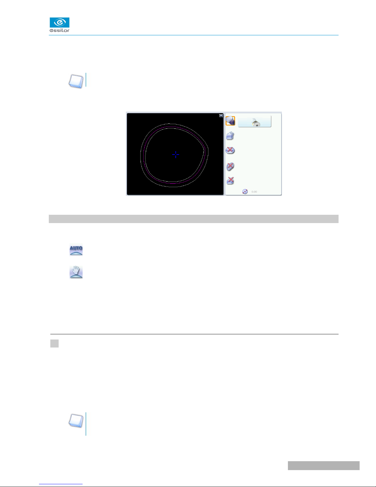
a. Automatic beveling
Call up the desired shape located on the tracer or on the job management program.
The shape is displayed on the edger work screen.
After the tracing of a rimmed frame:
• The bevel finish is selected by default.
• The automatic mode is selected by default.
If you want to produce a bevel less than 0.75mm high, configure the bevel directly on the
screen.
>
>
>
1
USER MANUAL> II. EDGING A LENS
21
Pro-E 600 > v1 -02.17
Page 19
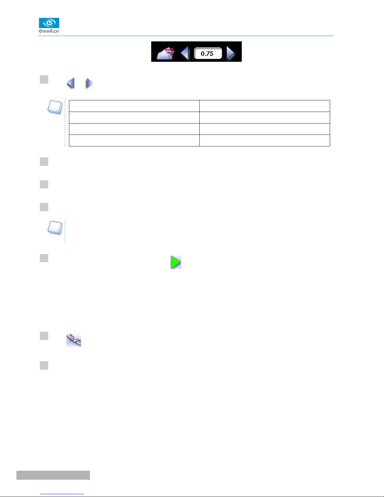
Press and to adjust the height of the bevel.
Height (mm)
By default 0.75
Minimum 0.30
Maximum 0.75
Select lens material.
Select the type of cycle.
Choose whether or not to polish and/or chamfer your lens.
For more information, consult the section Edging a lens > Perform a polishing (F p.65) and Edging a
lens > Perform a chamfering (F p.66).
Press the “cycle start” button (front face) or .
The door closes, the lens is clamped, then the feeling operation starts.
The edging cycle starts.
When the edging cycle is finished, the retouch screen is displayed.
Press to release the lens.
If necessary, retouch the lens.
Otherwise, start edging the second lens. Select the lens directly on the screen, on the left or right of the
work area.
The edging screen for the second lens is displayed. All finishes chosen and the modifications made
are kept.
>
>
>
>
2
3
4
5
6
7
8
Pro-E 600 > v1 -02.17
22
USER MANUAL> II. EDGING A LENS
Page 20
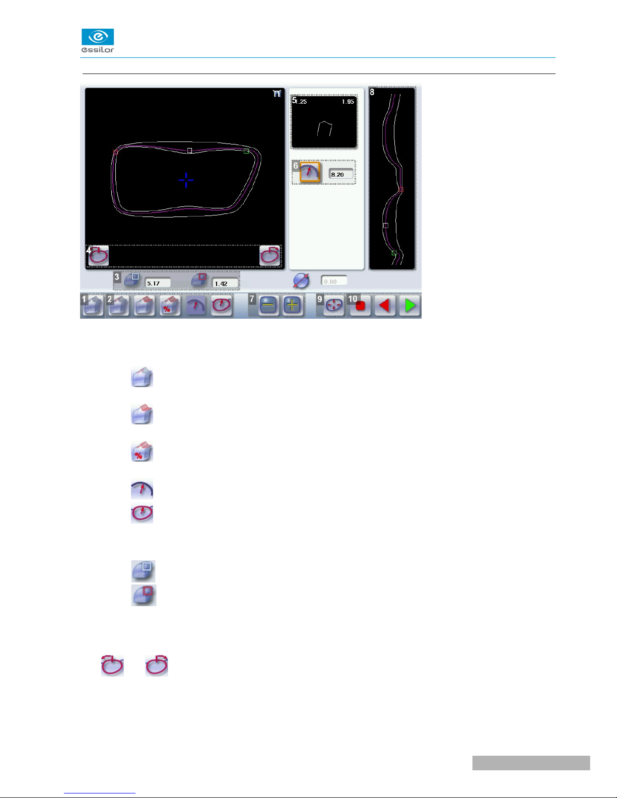
b. Legend screen for customized bevels
1. Automatic bevel
2. Customized bevels
◦ Front surface tracking: the crest of the bevel is positioned at a constant distance from the
front surface.
◦ Rear surface tracking: the crest of the bevel is positioned at a constant distance from the
rear surface.
◦ Distributed bevel: the position of the crest of the bevel is proportional to the thickness of
the lens, with respect to the front surface.
◦ Lens curve tracking: the camber of the bevel is adjustable.
◦ Frame rim tracking: the bevel tracks the groove precisely, according to the data obtained on
frame tracing.
3. Lens thickness
◦ Maximum lens thickness - represented by the white square along the shape.
◦ Minimum lens thickness - represented by the red square along the shape.
4. Cursor movement
The cursor is represented by the green square along the shape. To move it, select it directly or use the
and buttons.
5. Zoom window
Represents the bevel profile and indicates the distance between the bevel crest and the front and rear
surfaces of the lens at the cursor position.
USER MANUAL> II. EDGING A LENS
23
Pro-E 600 > v1 -02.17
Page 21
6. Bevel distribution value
Distribution value modifiable for:
◦ front/rear surface tracking
◦ a distributed bevel
◦ lens curve tracking
7. Modify the selected value
Reduce or increase the distribution value.
8. Bevel trajectory
Flat representation of the lens making it possible to assess the distances between the bevel crest and the
front & rear surfaces of the lens.
9. Trajectory modification
◦ General modification of the bevel curve
◦ Modification of the bevel curve at a particular point
◦ Displacement of the bevel curve
10. Navigation
◦ Stop the cycle
◦ Back to the main edging screen
◦ Start the edging cycle
c. Customized beveling
The use of the customized bevel depends on 2 parameters: the frame and the lens. Before starting your job,
identify the major constraint.
BEVEL FRAME LENS ADVANTAGES
Classic Lens for which the front surface
base is approximately equal to
the frame base.
Makes it possible to do an aesthetically pleasing
job. The lens material does not protrude beyond
the front of the frame.
Classic Lenticular lens&, Executive lens&Makes it possible to do a job with specific lenses.
Classic Thin lens Makes it possible to balance out the bevel when
thin lenses are used.
Flat base
High base
Thin lens for which the front
surface base is approximately
equal to the frame base.
Makes it possible to retrieve the frame base in a
pattern tracing (base = 0).
Particular groove
(groove with
meniscus&)
Thin lens for which the base is
approximately equal to the
meniscus of the groove.
Compliance with original shape.
Job using a specific frame.
Pro-E 600 > v1 -02.17
24
USER MANUAL> II. EDGING A LENS
Page 22
Call up the desired shape located on the tracer or on the job management program.
The shape is displayed on the edger work screen.
After the tracing of a rimmed frame:
• The bevel finish is selected by default.
• The automatic mode is selected by default.
Select lens material.
Change the edging mode. Press to select customized mode .
Select the type of cycle.
Choose whether or not to polish and/or chamfer your lens.
For more information, consult the section Edging a lens > Perform a polishing (F p.65) and Edging a
lens > Perform a chamfering (F p.66).
Press the “cycle start” button (front face) or .
The door closes, the lens is clamped and then felt.
The customized bevel finish screen is displayed.
Select the type of customized bevel you want to do.
To avoid reproducing defects when tracking a frame rim, check that the frame groove is in perfect
condition and that the hinges are properly closed. All groove imperfections will be reproduced.
Press and to adjust the distribution value if required.
Press .
The edging cycle starts.
When the edging cycle is finished, the retouch screen is displayed.
>
>
>
>
>
>
1
2
3
4
5
6
7
8
9
USER MANUAL> II. EDGING A LENS
25
Pro-E 600 > v1 -02.17
Page 23
Press to release the lens.
If necessary, retouch the lens.
Otherwise, start edging the second lens. Select the lens directly on the screen, on the left or right of the
work area.
The edging screen for the second lens is displayed. All finishes chosen and the modifications made
are kept.
d. Modifying the bevel curve
Once you have configured the desired type of customized bevel, you can complete your customization by
moving the bevel curve towards the front or rear surface of the lens so it takes on its shape.
Press from the customized bevel finish screen.
You will access the trajectory modification screen.
Press to select the general modification of the bevel curve.
Use the buttons and to move the bevel curve:
• Press to move the curve towards the front surface of the lens.
• Press to move the curve towards the rear surface of the lens.
The curve cannot be moved more than the minimum distance between the front and rear surfaces
observed on the bevel before the modification.
The position of the bevel as well as the distances between the crest of the bevel and the front and
rear surfaces of the lens are displayed in the zoom window at the position of the cursor.
Press the “cycle start” button (front face) or .
The edging cycle starts.
When the edging cycle is finished, the retouch screen is displayed.
Press to release the lens.
>
>
>
>
>
10
11
1
2
3
4
5
Pro-E 600 > v1 -02.17
26
USER MANUAL> II. EDGING A LENS
Page 24
If necessary, retouch the lens.
Otherwise, start edging the second lens. Select the lens directly on the screen, on the left or right of the
work area.
The edging screen for the second lens is displayed. All finishes chosen and the modifications made
are kept.
e. Modifying the bevel curve at a particular point
Once you have configured the desired type of customized bevel, you can complete your customization by
partially moving the bevel curve towards the front or rear surface of the lens so it takes on its shape.
Press from the customized bevel finish screen.
You will access the trajectory modification screen.
Press to select modification of the bevel curve at a particular point.
Using the cursor, select the point on the curve that you want to move or click directly on the position of
the shape you want to modify.
Use the buttons and to move the point on the selected curve.
• Press to move it towards the front surface of the lens.
• Press to move it towards the rear surface of the lens.
The curve cannot be moved more than the minimum distance between the front and rear surfaces
observed on the bevel before the modification.
The position of the bevel as well as the distances between the crest of the bevel and the front and
rear surfaces of the lens are displayed in the zoom window at the position of the cursor.
Press the “cycle start” button (front face) or .
Press to go back to the customized bevel finish screen.
For the second lens, the customized bevel icon is pre-selected and the trajectory modification icon is
displayed.
>
>
>
>
6
1
2
3
4
5
USER MANUAL> II. EDGING A LENS
27
Pro-E 600 > v1 -02.17
Page 25
f. Displacing the bevel curve
The displacement of the bevel curve makes it possible to move the bevel without modifying its curve.
Press from the customized bevel finish screen.
You will access the trajectory modification screen.
Press to select the displacement of the bevel curve.
Use the and buttons to displace the bevel curve:
• Press to displace it towards the front surface of the lens.
• Press to displace it towards the rear surface of the lens.
The position of the bevel as well as the distances between the crest of the bevel and the front and
rear surfaces of the lens are displayed in the zoom window at the position of the cursor.
Press the “cycle start” button (front face) or .
The edging cycle starts.
When the edging cycle is finished, the retouch screen is displayed.
Press to release the lens.
If necessary, retouch the lens.
Otherwise, start edging the second lens. Select the lens directly on the screen, on the left or right of the
work area.
The edging screen for the second lens is displayed. All finishes chosen and the modifications made
are kept.
3. HIGH-BASE BEVELING
This section describes the procedures for the creation of a high-base bevel:
• Description of the high-base bevel screens, (F p.29)
• Produce a high-base bevel in “automatic trajectory” mode or “front surface tracking” mode. (F p.31)
>
>
>
>
>
1
2
3
4
5
6
Pro-E 600 > v1 -02.17
28
USER MANUAL> II. EDGING A LENS
Page 26
The use of the high-base bevel depends on two parameters: the frame and the lens.
• Concerning the lens, the main constraint is the thickness of the nasal and temporal edges.
• Concerning the frame, the crucial elements are the bridge and shape of the groove. The hinge is an
additional factor in the case of a metal frame, the arms for a plastic frame.
For this job, the lens base must always match the frame base perfectly. Too great a difference
between the two could be detrimental to the quality of your job.
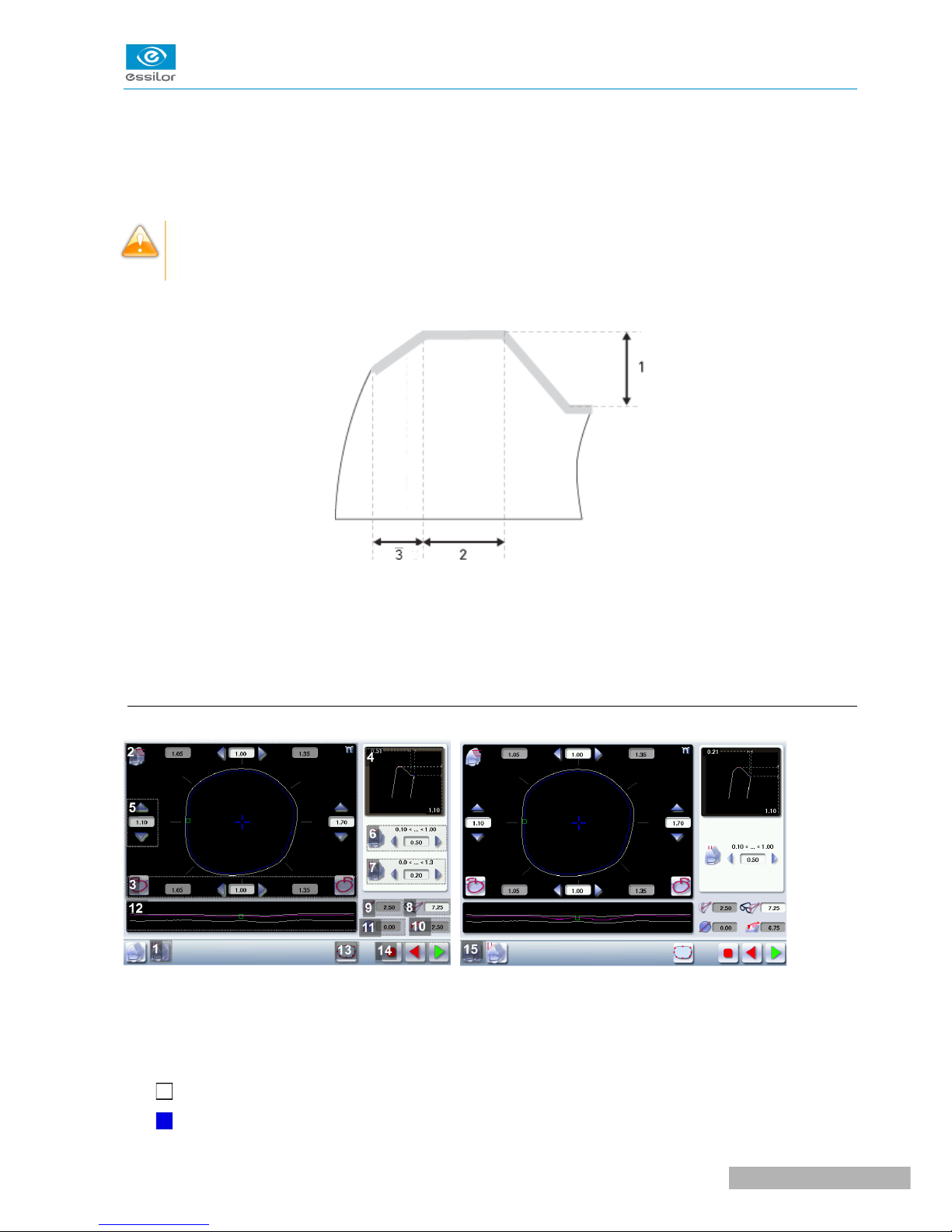
Cross-sectional view of a high-base bevel
1: Shelf bevel value
2: Width of the flat side of the bevel
3. Front surface tracking value
a. Captioned screens
1. High-base bevel “front surface tracking” screen
2. Work area
Image of the shape to be edged:
Frame shape at bottom of groove
Bevel trajectory on rear surface
USER MANUAL> II. EDGING A LENS
29
Pro-E 600 > v1 -02.17
Page 27

Bevel trajectory on rear surface if the lens used is too thin to achieve the desired finish.
3. Cursor movement
The cursor is represented by the square located along the shape. To move it, select it directly or use the
and buttons.
4. Zoom window
Represents the bevel profile at the position of the cursor.
5. Shelf bevel value (8 or 4 values)
◦ Nasal (the value must be between 0.25 and 3 mm)
◦ Mid-nasal (the value must be between 0.25 and 3 mm)
◦ Upper (the value must be between 0.25 and 3 mm)
◦ Mid-upper (the value must be between 0.25 with 3 mm)
◦ Temporal (the value must be between 0.25 and 3 mm)
◦ Mid-temporal (the value must be between 0.25 and 3 mm)
◦ Lower (the value must be between 0.25 and 3 mm)
◦ Mid-lower (the value must be between 0.25 and 3 mm)
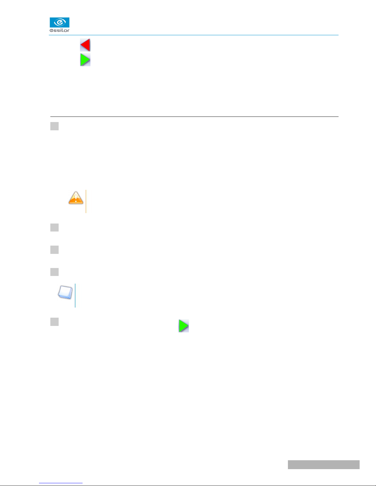
6. Width of the flat side of the bevel
The value of the flat side of the bevel must be between 0.1 mm and 1 mm.
7. Front surface tracking value
The front surface tracking value must be between 0 mm and 1.3 mm. This value is definable only in the
“front surface tracking” screen.
8. Frame base
9. Lens base
10. Bevel Base_Range of values of the lens base necessary for the frame
If the lens base used is out of range: the range values are shown in red.
11. Reminder of size reduction/increase applied to lens diameter
12. Window showing the bevel trajectory on the lens section
Centre of the flat side of the bevel
Front surface/rear surface of lens
13. Number of shelf bevel values
Transition from 4 to 8 shelf bevel values.
Transition from 8 to 4 shelf bevel values.
14. Navigation
◦ Stop the cycle
Pro-E 600 > v1 -02.17
30
USER MANUAL> II. EDGING A LENS
Page 28
◦ Back to the main edging screen
◦ Start the edging cycle
15. High-base bevel screen “automatic trajectory”
In this screen, the trajectory on the lens section cannot be configured: it is calculated automatically. This
calculation harmonises as best as possible, the lens base, the base of the frame and the shape.
b. High-base beveling
Call up the desired shape located on the tracer or on the job management program.
The shape is displayed on the edger work screen.
After the tracing of a high-base frame:
• The high-base finish is selected by default.
• The customized mode is selected by default.
In high-base finish, you cannot polish your bevel. However, the high-base wheel has been
designed to provide an equivalent finish on polycarbonate lenses.
Select lens material.
Select the type of cycle.
Choose to create or not to create a small or a large chamfer on the rear surface of the lens.
For more information, consult the section Edging a lens > Perform a polishing (F p.65) and Edging a
lens > Perform a chamfering (F p.66).
Press the “cycle start” button (front face) or .
The door closes, the lens is clamped and then felt.
The high-base bevel finish screen “automatic trajectory” is displayed by default.
>
>
>
>
1
2
3
4
5
USER MANUAL> II. EDGING A LENS
31
Pro-E 600 > v1 -02.17
Page 29

By default, the edger shows the values corresponding to the frame material (metal or plastic).
Check and modify these values according to the thickness of your lens and your frame.
You can:
• produce a high-base bevel in “automatic trajectory” mode, (F p.32)
• produce a high-base bevel in “front surface tracking” mode. (F p.34)
High-base bevel in “automatic trajectory” mode
Press to select the bevel in “automatic trajectory ” mode.
The following screen will appear:
>
1
Pro-E 600 > v1 -02.17
32
USER MANUAL> II. EDGING A LENS
Page 30
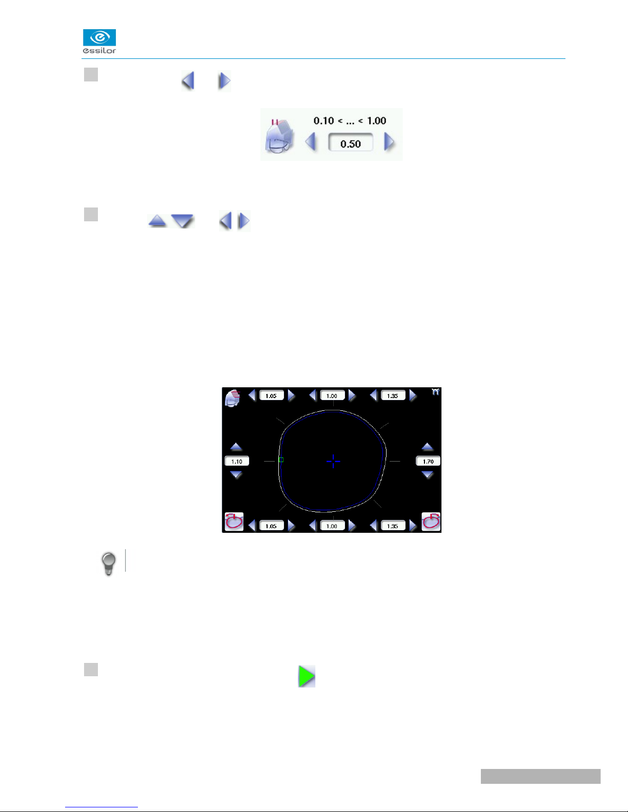
Press the buttons and on the right of your screen to modify the width of the flat side of the bevel.
The result can be viewed in the zoom window.
Press the and buttons to modify the shelf bevel value at each point of the shape in
each area:
• Temporal
• Mid-temporal
• Nasal
• Mid-nasal
• Upper
• Mid-upper
• Lower
• Mid-lower
Move the cursor along the shape to see the bevel profile in the zoom window.
The edger calculates the shelf bevel value to be applied between each of the four points in each area.
The bevel trajectory on the rear surface is modified in the work screen. The result can be viewed in
the zoom window.
Press the “cycle start” button (front face) or .
The edging cycle starts.
When the edging cycle is finished, the retouch screen is displayed.
>
>
>
>
>
2
3
4
USER MANUAL> II. EDGING A LENS
33
Pro-E 600 > v1 -02.17
Page 31

Press to release the lens.
If necessary, retouch the lens.
Otherwise, start edging the second lens. Select the lens directly on the screen, on the left or right of the
work area.
The edging screen for the second lens is displayed. All finishes chosen and the modifications made
are kept.
High-base bevel in “front surface tracking” mode
Press to select the bevel in “front surface tracking” mode.
The following screen will appear:
Press the buttons and on the right of your screen to modify the width of the flat side of the bevel.
The result can be viewed in the zoom window.
>
>
>
5
6
1
2
Pro-E 600 > v1 -02.17
34
USER MANUAL> II. EDGING A LENS
Page 32

Press the and buttons to modify the shelf bevel value at each point of the shape in
each area:
• Temporal
• Mid-temporal
• Upper
• Mid-upper
• Nasal
• Mid-nasal
• Lower
• Mid-lower
Move the cursor along the shape to see the bevel profile in the zoom window.
The edger calculates the shelf bevel value to be applied between each of the four points in each area.
The bevel trajectory on the rear surface is modified in the work screen. The result can be viewed in
the zoom window.
Press the buttons and on the right of your screen to modify the value of front surface tracking.
The result can be viewed in the zoom window and the display window of the bevel trajectory on the
lens section.
Press the “cycle start” button (front face) or .
The edging cycle starts.
>
>
>
>
3
4
5
USER MANUAL> II. EDGING A LENS
35
Pro-E 600 > v1 -02.17
Page 33

When the edging cycle is finished, the retouch screen is displayed.
Press to release the lens.
If necessary, retouch the lens.
Otherwise, start edging the second lens. Select the lens directly on the screen, on the left or right of the
work area.
The edging screen for the second lens is displayed. All finishes chosen and the modifications made
are kept.
4. PERFORM A STEP BEVEL
The step bevel finishing is active and available only if the tool is installed on the “small tools” module.
Prerequisite:
Allen key
Blocking key
Tool for “wheel” removal
This section describes:
• the installation procedure for the step bevel tool (F p.37)
• the procedures relating to the creation of a Step bevel:
◦ description of the Step bevel screens (F p.41)
◦ perform a Step bevel in “automatic trajectory” mode (F p.43) or “front surface tracking” mode.
(F p.45)
The use of the step bevel is determined by two parameters: frame and lens.
• Concerning the lens, the main constraint is the thickness of the nasal and temporal edges.
• Concerning the frame, the crucial elements are the bridge and shape of the groove. The hinge is an
additional factor in the case of a metal frame, the arms for a plastic frame.
>
>
6
7
Pro-E 600 > v1 -02.17
36
USER MANUAL> II. EDGING A LENS
Page 34

For this job, the lens base must always match the frame base perfectly. Too great a difference
between the two could be detrimental to the quality of your job.
Cross-section of a step bevel
1: Value of shelf bevel of rear surface
2: Width of the flat side of the bevel
3. Front surface tracking value
a. Install the step bevel tool
You will need the following:
Allen key
Blocking key
Tool for “wheel” removal
Step wheel in its set-up tool
From the working screen of your edger, press (tool wear indicator) for several seconds to access
the screen for tool changes.
1
2
USER MANUAL> II. EDGING A LENS
37
Pro-E 600 > v1 -02.17
Page 35

The following screen will appear: missing screen
Press to select the step bevel wheel: CX3831.
Press to confirm the tool.
The GMD module moves to facilitate the operation.
Press to receive more image information on the tool assembly/dismantling procedure.
Press to cancel the action.
The following message appears: remove the chamfering wheel and replace it with the step wheel.
>
>
>
3
4
Pro-E 600 > v1 -02.17
38
USER MANUAL> II. EDGING A LENS
Page 36

Position the blocking key on the back axle of the chamfering wheel, and insert the Allen key into the
screw at the center of the wheel and unscrew (towards yourself) the wheel, using the Allen key.
Remove the chamfering wheel and the spacer.
Position the step bevel wheel with its mounting accessory on the axle.
Tighten (towards yourself) the step bevel wheel using the Allen key.
5
6
7
8
USER MANUAL> II. EDGING A LENS
39
Pro-E 600 > v1 -02.17
Page 37

Ensure that the tool is correctly fixed onto the axle using the keys.
Remove the mounting tool and the Allen key
The wheel is installed.
When replacing a chamfering wheel with a step bevel wheel, or cleaning the machine, the
statistics will be saved by default.
>The icon appears by default at the bottom of the screen.
In case of replacement:
• of the chamfering wheel with a new step bevel wheel: you must press to reset
the statistics to 0.
The icon appears, the statistics are cleared.
• of the step bevel wheel with a new chamfering wheel: you must press to reset
the statistics to 0.
The icon appears, the statistics are cleared.
Press to confirm the tool change, then to exit the menu.
>
9
10
Pro-E 600 > v1 -02.17
40
USER MANUAL> II. EDGING A LENS
Page 38

b. Captioned screens
1. Automatic trajectory step bevel screen.
In this screen, the trajectory on the lens section cannot be configured: it is calculated automatically. This
calculation harmonises as best as possible, the lens base, the base of the frame and the shape.
2. Work area
Image of the shape to be edged:
Frame shape at bottom of groove
Bevel trajectory on rear surface
Bevel trajectory on rear surface if the lens used is too thin to achieve the desired finish.
3. Cursor movement
The cursor is represented by the square located along the shape. To move it, select it directly or use the
and buttons.
4. Zoom window
Represents the bevel profile at the position of the cursor.
5. Shelf bevel value (8 or 4 values)
◦ Nasal (the value must be between 0.40 and 3 mm)
◦ Mid-nasal (the value must be between 0.40 and 3 mm)
◦ Upper (the value must be between 0.40 and 3 mm)
◦ Mid-Upper (the value must be between 0.40 and 3 mm)
◦ Temporal (the value must be between 0.40 and 3 mm)
◦ Mid-temporal (the value must be between 0.40 and 3 mm)
◦ Lower (the value must be between 0.40 and 3 mm)
◦ Mid-lower (the value must be between 0.40 and 3 mm)
6. Width of the flat side of the bevel
The value of the flat side of the bevel must be between 0.1 mm and 2 mm.
7. back chamfer of assembly aid
USER MANUAL> II. EDGING A LENS
41
Pro-E 600 > v1 -02.17
Page 39

8. Front surface tracking step bevel screen
9. Front surface tracking value
The value of front surface tracking must be between 0 mm and 1.3 mm. This value is definable only in
the “front surface tracking” screen.
10. Frame base
11. Lens base
12. Bevel Base_Range of values of the lens base necessary for the frame
If the lens base used is out of range: the range values are shown in red.
13. Reminder of size reduction/increase applied to lens diameter
14. Window showing the bevel trajectory on the lens section
Centre of the flat side of the bevel
Front surface/rear surface of lens
15. Number of shelf bevel values
Transition from 4 to 8 shelf bevel values.
Transition from 8 to 4 shelf bevel values.
16. Navigation
◦ Stop the cycle
◦ Back to the main edging screen
◦ Start the edging cycle
c. Perform a Step bevel
Call up the desired shape located on the tracer or on the job management program.
The shape is displayed on the edger work screen.
After the tracing of a high-base frame:
• The step finish is selected by default.
• The customized mode is selected by default.
In the step finish, you cannot polish your bevel. Nevertheless, the step wheel was designed to
create a finish that is equivalent to polycarbonate lenses.
Press to select the Step bevel.
>
>
1
2
Pro-E 600 > v1 -02.17
42
USER MANUAL> II. EDGING A LENS
Page 40

The button appears grayed if the step bevel wheel was not mounted beforehand: .
Select lens material.
You cannot perform a bevel step on the Trivex lensesTM and glass lenses.
Select the type of cycle.
Press the “cycle start” button (front face) or .
The door closes, the lens is clamped and then felt.
The “automatic trajectory” step finish screen is displayed by default.
By default, the edger shows the values corresponding to the frame material (metal or plastic).
Check and modify these values according to the thickness of your lens and your frame.
You can:
• perform a step bevel in “automatic trajectory” mode (F p.43),
In this mode, the bevel trajectory follows the base of the frame as closely as possible.
• perform a step bevel in “front surface tracking” mode (F p.45).
In this mode, the trajectory of bevel follows the front surface lens base as closely as possible.
Step bevel in “automatic trajectory” mode
Press to select the bevel in “automatic trajectory ” mode.
The following screen will appear:
>
>
>
3
4
5
1
USER MANUAL> II. EDGING A LENS
43
Pro-E 600 > v1 -02.17
Page 41

Press the buttons and on the right of your screen to modify the width of the flat side of the bevel.
The result can be viewed in the zoom window.
Press on the buttons and to modify the shelf bevel value in each point of the shape in
each of the areas, 4 or 8 areas:
• Temporal
• Mid-temporal
• Upper
• Mid-upper
• Nasal
• Mid-nasal
• Lower
• Mid-lower
Move the cursor along the shape to see the bevel profile in the zoom window.
>
2
3
Pro-E 600 > v1 -02.17
44
USER MANUAL> II. EDGING A LENS
Page 42

The edger calculates the shelf bevel value to be applied between each of the four or eight points of
each area.
The bevel trajectory on the rear surface is modified in the work screen. The result can be viewed in
the zoom window.
Press to perform a back chamfer of the assembly aid.
The chamfer is selected .
The result can be viewed in the zoom window.
Press the “cycle start” button (front face) or .
The edging cycle starts.
When the edging cycle is finished, the retouch screen is displayed.
Press to release the lens.
If necessary, retouch the lens.
Otherwise, start edging the second lens. Select the lens directly on the screen, on the left or right of the
work area.
The edging screen for the second lens is displayed. All finishes chosen and the modifications made
are kept.
Step bevel in “front surface tracking” mode
Press to select the bevel in “front surface tracking” mode.
The following screen will appear:
>
>
>
>
>
>
>
>
4
5
6
7
1
USER MANUAL> II. EDGING A LENS
45
Pro-E 600 > v1 -02.17
Page 43

Press the and buttons to modify the shelf bevel value at each point of the shape in
each area:
• Temporal
• Mid-temporal
• Upper
• Mid-upper
• Nasal
• Mid-nasal
• Lower
• Mid-lower
Move the cursor along the shape to see the bevel profile in the zoom window.
2
Pro-E 600 > v1 -02.17
46
USER MANUAL> II. EDGING A LENS
Page 44

The edger calculates the shelf bevel value to be applied between each of the four or eight points of
each area.
The bevel trajectory on the rear surface is modified in the work screen. The result can be viewed in
the zoom window.
Press the buttons and on the right of your screen to modify the width of the flat side of the bevel.
The result can be viewed in the zoom window.
Press the and buttons on the right of your screen to modify the front surface tracking value.
The result can be viewed in the zoom window and in the window showing the bevel trajectory on the
lens section.
Press to perform a back chamfer of the assembly aid.
>
>
>
>
3
4
5
USER MANUAL> II. EDGING A LENS
47
Pro-E 600 > v1 -02.17
Page 45

The chamfer is selected .
The result can be viewed in the zoom window.
Press the “cycle start” button (front face) or .
The edging cycle starts.
When the edging cycle is finished, the retouch screen is displayed.
Press to release the lens.
If necessary, retouch the lens.
Otherwise, start edging the second lens. Select the lens directly on the screen, on the left or right of the
work area.
The edging screen for the second lens is displayed. All finishes chosen and the modifications made
are kept.
5. GROOVING
This section describes the procedures for the creation of a groove:
• In automatic mode (F p.49), you do not have to configure anything. All the data is automatically
retrieved from the tracer. The lens edging starts automatically after the feeling cycle.
• In customized mode (F p.51), you can perform a front/rear surface tracking, a distributed groove
or a lens curve tracking. You can also do the following:
◦ a general modification of the groove curve (F p.53)
◦ a modification at a point of the groove curve (F p.54)
◦ a displacement of the groove curve (F p.55)
• You can consult the description of the customized groove screen.
>
>
>
>
>
6
7
8
Pro-E 600 > v1 -02.17
48
USER MANUAL> II. EDGING A LENS
Page 46

In certain cases, the lens base or thickness makes grooving impossible.
> An error message is displayed.
> The white central line becomes red on the entire contour of the lens.
a. Automatic grooving
Call up the desired shape located on the tracer or on the job management program.
The shape is displayed on the edger work screen.
After tracing a pattern, demo lens or re-cut lens, without any drilling settings:
• the groove finish is selected by default.
• the automatic mode is selected by default.
If you wish to produce a groove the depth and the width of which are less than 0.60 mm:
Directly define the groove in the screen.
Press and to regulate the depth and the width of the groove
Depth (mm) Width (mm)
By default 0.60 0.60
Minimum 0.20 0.60
Maximum 1.20 1.20
Select lens material.
Select the type of cycle.
Choose whether or not to polish and/or chamfer your lens.
For more information, consult the section Edging a lens > Perform a polishing (F p.65) and Edging a
lens > Perform a chamfering (F p.66).
Press the “cycle start” button (front face) or .
The door closes, the lens is clamped and then felt.
>
>
>
1
2
3
4
5
6
USER MANUAL> II. EDGING A LENS
49
Pro-E 600 > v1 -02.17
Page 47

The edging cycle starts.
When the edging cycle is finished, the retouch screen is displayed.
Press to release the lens.
If necessary, retouch the lens.
Otherwise, start edging the second lens. Select the lens directly on the screen, on the left or right of the
work area.
The edging screen for the second lens is displayed. All finishes chosen and the modifications made
are kept.
b. Customized groove legend screen
1. Automatic groove
2. Customized grooves
◦ Front surface tracking: the middle of the groove is positioned at a constant distance from
the front surface.
◦ Rear surface tracking: the middle of the groove is positioned at a constant distance from
the rear surface.
◦ Distributed groove: the middle of the groove is positioned in proportion to the thickness of
the lens, with respect to the front surface.
>
>
>
7
8
Pro-E 600 > v1 -02.17
50
USER MANUAL> II. EDGING A LENS
Page 48

◦ Lens curve tracking: the camber of the groove is adjustable.
3. Lens thickness
◦ Maximum lens thickness - represented by the white square along the shape
◦ Minimum lens thickness - represented by the red square along the shape
4. Cursor movement
The cursor is represented by the green square along the shape. To move it, select it directly or use the
and buttons.
5. Zoom window
Distance between the edges of the groove and the front & rear surfaces of the lens at the position of the
cursor.
6. Groove settings
◦ Distribution value - according to the type of customized groove selected
◦ Groove depth (in mm)
◦ Groove width (in mm)
7. Modify the selected setting
8. Groove trajectory
Flat representation of the lens making it possible to measure the distances between the groove and the
front & rear surfaces of the lens.
9. Modify the trajectory
◦ General modification of the groove curve
◦ Modification of a point in the groove curve
◦ Displacement of the groove curve
10. Navigation
◦ Stop the cycle
◦ Back to the main edging screen
◦ Start the edging cycle
c. Customized grooving
The use of the customized groove depends on 2 parameters: the frame and the lens. Before starting your
job, identify the major constraint.
USER MANUAL> II. EDGING A LENS
51
Pro-E 600 > v1 -02.17
Page 49

GROOVE FRAME LENS ADVANTAGES
Standard groove Lens for which the front
surface base is approximately
equal to the frame base.
Makes it possible to do an aesthetically
pleasing job. The lens material does not
protrude beyond the front of the frame.
Standard groove Lens for which the rear
surface base is not as high as
the front surface base.
Minimises the risks of the nylon thread
coming out.
Standard groove Thin lens Makes it possible to balance out the groove
when thin lenses are used.
Flat base
High base
Thin lens for which the front
surface base is approximately
equal to the frame base.
In the event of pattern tracing (base = 0),
makes it possible to retrieve the frame base.
Call up the desired shape located on the tracer or on the job management program.
The shape is displayed on the edger work screen.
After tracing a pattern, demo lens or recut lens, without any drilling settings:
• the groove finish is selected by default.
• the automatic mode is selected by default.
Select lens material.
Change the edging mode. Press to select customized mode .
Select the type of cycle.
Choose whether or not to polish and/or chamfer your lens.
For more information, consult the section Edging a lens > Perform a polishing (F p.65) and Edging a
lens > Perform a chamfering (F p.66).
Press the “cycle start” button (front face) or .
The door closes, the lens is clamped and then felt.
The customized groove finish screen is displayed.
Select the type of customized groove you want to do.
>
>
>
>
1
2
3
4
5
6
7
Pro-E 600 > v1 -02.17
52
USER MANUAL> II. EDGING A LENS
Page 50

Select the values you want to modify and press and to adjust them if necessary
Press .
The edging cycle starts.
When the edging cycle is finished, the retouch screen is displayed.
Press to release the lens.
If necessary, retouch the lens.
Otherwise, start edging the second lens. Select the lens directly on the screen, on the left or right of the
work area.
The edging screen for the second lens is displayed. All finishes chosen and the modifications made
are kept.
d. Modifying the groove curve
Once you have configured the desired type of customized groove, you can complete your customization by
moving the groove curve towards the front or rear surface of the lens so it takes on its shape.
Press from the customized groove finish screen.
You will access the trajectory modification screen.
Press to select the general modification of the groove curve.
Use the buttons and to move the groove curve.
• Press to move the curve towards the front surface of the lens.
• Press to move the curve towards the rear surface of the lens.
The curve cannot be moved more than the minimum distance between the front and rear surfaces
observed on the groove before the modification.
The position of the groove as well as the distances between the center of the groove and the front &
rear surfaces of the lens are displayed in the zoom window.
>
>
>
>
>
8
9
10
11
1
2
3
USER MANUAL> II. EDGING A LENS
53
Pro-E 600 > v1 -02.17
Page 51

Press the “cycle start” button (front face) or .
The edging cycle starts.
When the edging cycle is finished, the retouch screen is displayed.
Press to release the lens.
If necessary, retouch the lens.
Otherwise, start edging the second lens. Select the lens directly on the screen, on the left or right of the
work area.
The edging screen for the second lens is displayed. All finishes chosen and the modifications made
are kept.
e. Modifying a point in the groove curve
Once you have configured the desired type of customized groove, you can complete your customization by
moving the groove curve towards the front or rear surface of the lens so it takes on its shape.
Press from the customized groove finish screen.
You will access the trajectory modification screen.
Press to select modification of a point in the groove curve.
Using the cursor, select the point on the curve that you want to move or click directly on the screen.
Use the buttons and to move the point on the selected curve.
• Press to move it towards the front surface of the lens.
• Press to move it towards the rear surface of the lens.
The curve cannot be moved more than the minimum distance between the front and rear surfaces
observed on the groove before the modification.
The position of the groove as well as the distances between the center of the groove and the front &
rear surfaces of the lens are displayed in the zoom window.
>
>
>
>
>
4
5
6
1
2
3
4
Pro-E 600 > v1 -02.17
54
USER MANUAL> II. EDGING A LENS
Page 52

Press .
Press to go back to the customized bevel finish screen.
For the second lens, the customized groove icon is pre-selected and the trajectory modification icon
is displayed.
f. Displacement of the groove curve
The displacement of the groove curve enables you to move the groove without modifying its curve or
perimeter.
Press from the customized groove finish screen.
You will access the trajectory modification screen.
Press to select the displacement of the curve.
Use the and buttons to displace the curve.
• Press to displace it towards the front surface of the lens.
• Press to displace it towards the rear surface of the lens.
The position of the groove as well as the distances between the center of the groove and the front &
rear surfaces of the lens are displayed in the zoom window.
Press the “cycle start” button (front face) or .
The edging cycle starts.
When the edging cycle is finished, the retouch screen is displayed.
Press to release the lens.
If necessary, retouch the lens.
>
>
>
>
>
5
1
2
3
4
5
6
USER MANUAL> II. EDGING A LENS
55
Pro-E 600 > v1 -02.17
Page 53

Otherwise, start edging the second lens. Select the lens directly on the screen, on the left or right of the
work area.
The edging screen for the second lens is displayed. All finishes chosen and the modifications made
are kept.
6. PRODUCE A FLAT-EDGE FINISH
For a flat-edge finish, only automatic mode is accessible.
Call up the desired shape located on the tracer or on the job management program.
The shape is displayed on the edger work screen.
Select lens material.
Press to select the flat-edge finish.
Select the type of cycle.
Choose whether or not to polish and/or chamfer your lens.
For more information, consult the section Edging a lens > Perform a polishing (F p.65) and Edging a
lens > Perform a chamfering (F p.66).
Press the “cycle start” button (front face) or .
The door closes, the lens is clamped and then felt.
The edging cycle starts.
When the edging cycle is finished, the retouch screen is displayed.
Press to release the lens.
If necessary, retouch the lens.
Otherwise, start edging the second lens. Select the lens directly on the screen, on the left or right of the
work area.
>
>
>
>
>
1
2
3
4
5
6
7
8
Pro-E 600 > v1 -02.17
56
USER MANUAL> II. EDGING A LENS
Page 54

The edging screen for the second lens is displayed. All finishes chosen and the modifications made
are kept.
7. DO A MIXED JOB
In this section, you will find the required procedure to do a mixed job:
• Description of menu screens (F p.57)
• Configuring the mixed finish (F p.59)
This finish enables you to do mixed jobs such as the following:
• Groove - Groove
• Bevel - Groove
• Flat-edge - Groove
• Flat-edge - Bevel
To do a mixed finish, you need to define the points between which the two types of finish will be done. Only
the customized mode is thus accessible.
a. Legend screens
Main screen for mixed jobs
1. Modes available for a mixed finish
◦ Automatic mode: the position of the bevel or groove is automatically calculated according to
the information acquired when tracing the frame and feeling the lens.
>
USER MANUAL> II. EDGING A LENS
57
Pro-E 600 > v1 -02.17
Page 55
◦ Front surface tracking: the crest of the bevel or the middle of the groove is positioned at a
constant distance from the front surface.
◦ Distributed mixed finish: the crest of the bevel or the middle of the groove is positioned in
proportion to the thickness of the lens, with respect to the front surface.
2. Access to the area defining screen
Access on a 1:1 scale.
3. Cursor movement
The cursor is represented by the green square along the shape. To move it, select it directly or use the
and buttons.
4. Settings for area 1
◦ Bevel finish
◦ Groove finish
◦ Flat-edge finish
5. Zoom window
Display of the distance from the edges of the lens to the position of the cursor.
6. Position of the center of the groove or bevel
Value expressed in mm ('Front surface tracking' mode) or in % ('Distributed mixed finish' mode).
7. Settings for area 2
◦ Bevel finish
◦ Groove finish
◦ Flat-edge finish
8. Navigation
◦ Stop the cycle
◦ Return to the main edging screen without saving your changes
◦ Start the edging cycle
Area definition screen
Pro-E 600 > v1 -02.17
58
USER MANUAL> II. EDGING A LENS
Page 56

1. Lock / unlock the area delimitation points
2. Move the area delimitation points
3. Back to the main screen
4. Enable area delimitation on the touch screen
5. Modify the selected value
Legend of colours delimiting the shape areas:
(pink) Bevel finish
(yellow) / (orange) Groove finish (in the case of a Groove - Groove mixed job, the colours make it
possible to differentiate grooves with different parameters)
(black) Flat-edge finish
b. Configuring the mixed finish
Initiating a mixed finish
Call up the desired shape located on the tracer or on the job management program.
The shape is displayed on the edger work screen.
Select lens material.
Press to select mixed job mode.
Select your type of cycle.
>
1
2
3
4
USER MANUAL> II. EDGING A LENS
59
Pro-E 600 > v1 -02.17
Page 57

Choose whether or not to polish the lens.
You cannot do a chamfer on a mixed job.
For more information on polishing, refer to the section Edging a lens > Polishing (F p.65).
Press .
The door closes, the lens is clamped and then felt.
The mixed finish screen is displayed:
The default setting is the bevel - groove finish in automatic mode.
Customizing the mixed finish
Select the desired type of mixed finish.
Press to access the area definition screen.
The area definition screen is displayed on a 1:1 scale. You can thus refer to a sample lens placed on
the screen.
Select the finish you want in area 1, then area 2.
Press the button to unlock an area delimitation point.
Press the and buttons to move the unlocked point.
Press to move the delimitation points directly on the touch screen. The two points are then
unlocked. Drag them with the stylus.
If necessary, press to modify the position of the center of the groove or bevel using the buttons
and .
This value cannot be modified in automatic mode.
>
>
>
>
5
6
1
2
3
4
5
6
Pro-E 600 > v1 -02.17
60
USER MANUAL> II. EDGING A LENS
Page 58
If necessary, press and to modify the groove depth and width using the and
buttons.
Press .
The edging cycle starts.
When the edging cycle is finished, the retouch screen is displayed.
Press to release the lens.
If necessary, retouch the lens.
Otherwise, start edging the second lens. Select the lens directly on the screen, on the left or right of the
work area.
The edging screen for the second lens is displayed. All finishes chosen and the modifications made
are kept.
8. PERFORM A DRILLED JOB
Prerequisite: the edger's drilling function is only accessible if the tracer sends a shape with drilling
settings. For more information, consult the chapter Preparing a drilled job in the tracer manual.
You can do the drilling in automatic mode or in customized mode:
• In automatic mode (F p.62), you do not have anything to configure. The drilling angle consists of
the average value calculated at right angles with the front surface of the lens for each drilling point.
The lens edging starts automatically after the feeling cycle.
• In customized mode (F p.64), you can do the following:
◦ Drilling at right angles with the front or rear surface: you can modify the diameter but not the
drilling angle which is automatically calculated by the edger based on the lens curve.
◦ Customized drilling: you can modify the diameter and angle for each drilling point.
• You can consult the description of the customized drilling screen (F p.63).
Two different diameter drill bits are available: a 1 mm bit and a 0.8 mm bit. If the diameter of the drilling
point is smaller than that of the installed drill bit, an error message is displayed. Change the drill bit or
modify the diameter of the drilling points.
You can also create various combinations:
• Drilled bevel
>
>
>
7
8
9
10
USER MANUAL> II. EDGING A LENS
61
Pro-E 600 > v1 -02.17
Page 59

• Drilled high-base bevel
• Drilled groove
• Drilled mixed finish
a. Automatic drilling
Call up the desired shape located on the tracer or on the job management program.
The shape is displayed on the edger work screen.
After the tracing of a shape with drilling settings:
• The drilling function is selected by default.
• The automatic mode is selected by default.
Select lens material.
Select the type of finish.
Select the type of cycle.
Choose whether or not to polish and/or chamfer your lens.
For more information, consult the section Edging a lens > Perform a polishing (F p.65) and Edging a
lens > Perform a chamfering (F p.66).
Press the “cycle start” button (front face) or .
The door closes, the lens is clamped and then felt.
The edging cycle starts.
When the edging cycle is finished, the retouch screen is displayed.
Press to release the lens.
If necessary, retouch the lens.
Otherwise, start edging the second lens. Select the lens directly on the screen, on the left or right of the
work area.
The edging screen for the second lens is displayed. All finishes chosen and the modifications made
are kept.
>
>
>
>
>
>
1
2
3
4
5
6
7
8
Pro-E 600 > v1 -02.17
62
USER MANUAL> II. EDGING A LENS
Page 60

b. Legend screen for customized drilling
1. Type of drilling
◦ Perpendicular to the front surface
◦ Perpendicular to the rear surface
◦ Customized
2. Select the drilling points
◦ Nasal side
◦ Temporal side
◦ All drilling points
3. Modify the selected value
4. Modify the diameter
◦ diameter (mm)
◦ difference between the initial value and the modified value
5. Modify the drilling angle
◦ drilling angle (degrees)
◦ difference between the initial value and the modified value
6. Cross-sectional view
Cross-sectional view of the lens after the feeling cycle, showing the angle of the drill bit at the selected
drilling point.
USER MANUAL> II. EDGING A LENS
63
Pro-E 600 > v1 -02.17
Page 61

7. Reminder of size reduction/increase applied to lens diameter
8. Navigation
◦ Stop the cycle
◦ Return to the main edging screen without saving your changes
◦ Starting the cycle
c. Customized drilling
Call up the desired shape located on the tracer or on the job management program.
The shape is displayed on the edger work screen.
After the tracing of a shape with drilling settings:
• The drilling function is selected by default.
• The automatic mode is selected by default.
Select lens material.
Change the edging mode. Press to select customized mode .
Select the type of cycle.
Choose whether or not to polish and/or chamfer your lens.
For more information, consult the section Edging a lens > Perform a polishing (F p.65) and Edging a
lens > Perform a chamfering (F p.66).
Press the “cycle start” button (front face) or .
The feeling cycle starts.
The customized drilling screen is displayed.
Select the type of drilling you want to do.
If necessary, select the drilling point(s) you want to modify.
If necessary, modify the diameter and/or angle of the selected drilling point.
>
>
>
>
1
2
3
4
5
6
7
8
9
Pro-E 600 > v1 -02.17
64
USER MANUAL> II. EDGING A LENS
Page 62

The difference between the initial value and the modified one is displayed in the delta column.
Press .
The edging cycle starts.
When the edging cycle is finished, the retouch screen is displayed.
Press to release the lens.
If necessary, retouch the lens.
Otherwise, start edging the second lens. Select the lens directly on the screen, on the left or right of the
work area.
The edging screen for the second lens is displayed. All finishes chosen and the modifications made
are kept.
9. PERFORM A POLISHING
Press the button to activate/deactivate polishing.
LENS MATERIAL AVAILABLE OPTIONS
The polishing option is pre-selected and is strongly recommended by the manufacturer to
prevent small cracks.
Make sure you select the correct type of material for MHI (> 1.5) or Tribrid lenses and never
polish a lens of this type without water. Otherwise, the polishing wheel could suffer
irreversible damage.
The polishing option is pre-selected.
Not available
>
>
>
>
10
11
12
USER MANUAL> II. EDGING A LENS
65
Pro-E 600 > v1 -02.17
Page 63

The polishing option is not available for high-base jobs. However, the high-base wheel has been
designed to provide an equivalent finish on polycarbonate lenses.
10. CHAMFERING
The chamfer, also called counter-bevel, removes the sharp edge of the lens.
• Standard value of a small chamfer: 0.20 mm
• Standard value of a large chamfer: 0.40 mm
Before you select a type of chamfer, make sure it is compatible with the lens characteristics:
• Lens material
LENS MATERIAL AVAILABLE OPTIONS
The quality of the chamfer depends on the spraying. Make sure there is a
constant flow of water until the end of the chamfering operation.
Not available
• Thickness at the edge of the lens
LENS THICKNESS AVAILABLE OPTIONS
> 1.2 mm
between 1 and 1. 2 mm
< 1 mm
• Distance between the edge of the groove and the edge of the lens
DISTANCE AVAILABLE OPTIONS
> 0.8 mm
between 0.5 and 0.8 mm
< 0.5 mm
Pro-E 600 > v1 -02.17
66
USER MANUAL> II. EDGING A LENS
Page 64

The chamfers available also depend on the lens shape and the posiblock used when blocking.
Press on the buttons and to configure a small chamfer, a large chamfer or no chamfer on the
front and rear surfaces of the lens.
11. PERFORM A RETOUCHING
1. Diameter modification
2. Manual lens clamping
3. Retouch launch
Differences with the edging screen
The edging screen is different to the retouch
screen through:
• the presence of the posiblock,
• no frame thickness.
When the first-lens edging cycle is finished:
USER MANUAL> II. EDGING A LENS
67
Pro-E 600 > v1 -02.17
Page 65

Press to release the lens.
Proceed to lens assembly and check that edging was correctly configured.
Depending on your job:
• If your job is perfect, proceed with the machining of your second lens.
> All of the selected finishing options and modifications made are kept.
• If the lens requires adjustment, do a retouch on the edged lens to obtain optimal results.
Indicate the size reduction to be applied to the lens you want to retouch.
The chosen finish and the modifications made during the edging cycle are automatically selected.
Insert the lens in the posiblock holder.
To close the clamp shafts manually, do a long press on .
Press .
For a customized finish, the customized finish screen is displayed.
In all other cases, the door closes, the lens is clamped automatically, then the retouching starts.
Select the second lens to be edged directly on screen, on the left or right of the work area.
The edging screen for the second lens is displayed.
All finishes chosen and the modifications made are kept. The retouch done on the first lens is
automatically saved for the edging of the second lens.
>
>
>
>
>
>
1
2
3
4
5
6
Pro-E 600 > v1 -02.17
68
USER MANUAL> II. EDGING A LENS
Page 66

III. CONFIGURING THE EDGER
Page 67

This chapter allows you to set up the edger according to your use. You can:
• Configure the edger (F p.70) (hour, date, language, logins, screen-saver)
• Adjusting the precision of the edger (F p.72)
1. CONFIGURE THE EDGER
This section describes the procedures to:
• Set the time, date and language (F p.70)
• Access the connections and the network (F p.71)
• Configure a screensaver (F p.72)
a. Time, date and language
To access this menu from your work screen, select > > .
The following screen is displayed:
1. Time
Use the arrows and to set the time.
2. Date
Use the arrows and to set the date.
3. Type of date display
Select the type of display out of the available formats.
4. Language
Select the flag corresponding to your language.
5. Other languages
Pro-E 600 > v1 -02.17
70
USER MANUAL> III. CONFIGURING THE EDGER
Page 68

Press to display the other languages.
6. Confirm
Press to save the time.
Once the settings has been adjusted, press to go back to the work screen.
b. Connections
The connections are configured from the tracer. The screen which you access from the edger is only
available for consultation purposes.
To access this menu from your tracer work screen, select > > .
The following screen is displayed:
1. List of devices connected to the tracer
2. Settings linked to the configuration of the serial port
3. Settings linked to the configuration of the Ethernet port
4. Reinitialization of communication ports
Once the modification is made, press to return to the work screen.
USER MANUAL> III. CONFIGURING THE EDGER
71
Pro-E 600 > v1 -02.17
Page 69

c. Screensaver
This menu enables you to configure a screensaver.
To access this menu from your work screen, select > > .
The following screen is displayed:
1. Screensaver display
Enable or disable the screensaver.
2. Triggering
Set the waiting time before the display of the screensaver (in seconds).
3. Transition
Set the transition time between each image (in seconds).
Once the modification has been made, press to go back to the work screen.
2. ADJUSTING THE PRECISION OF THE EDGER
This menu enables you to adjust the precision of the edger. You can adjust:
• the diameter of the finished lenses (F p.72)
• the position of the bevel and groove (F p.73)
• the diameter of drill holes (F p.74)
• the chamfer (F p.75)
• the depth and width of the groove (F p.73)
• the position of high-base bevel (F p.78)
• the position of the step bevel (F p.78)
a. Adjusting the diameter of the finished lenses
If lenses of a particular material always seem too small or too big after edging, you can adjust their diameter
according to the type of frame.
To access that menu from your edger work screen, select > > .
Pro-E 600 > v1 -02.17
72
USER MANUAL> III. CONFIGURING THE EDGER
Page 70

The following screen is displayed:
1. Frame types
◦ Metal
◦ Plastic
◦ Optyl
◦ Drilled / Grooved / Flat
2. Lens materials
◦ Plastic
◦ Polycarbonate
◦ MHI
◦ Trivex
TM
◦ Glass (not available)
◦ Tribrid
TM
3. Adjust the lens diameter
a. Press the value to be modified.
> The numeric keypad is displayed.
b. Enter the new value.
◦ Negative value: the diameter will be smaller
◦ Positive value: the diameter will be larger
c. Press to confirm.
Once the modification is made, press to return to the work screen.
b. Adjusting the position of the bevel and groove
After edging a lens, if the position of the bevel or groove always seems too close to the front or rear surface,
you can adjust it.
USER MANUAL> III. CONFIGURING THE EDGER
73
Pro-E 600 > v1 -02.17
Page 71

To access that menu from your edger work screen, select > > .
The following screen is displayed:
1. Default bevel position
◦ Press to move the bevel towards the front surface of the lens.
◦ Press to move the bevel towards the rear surface of the lens.
2. Default polished bevel position
◦ Press to move the polished bevel towards the front surface of the lens.
◦ Press to move the polished bevel towards the rear surface of the lens.
3. Default groove position
◦ Press to move the groove towards the front surface of the lens.
◦ Press to move the groove towards the rear surface of the lens.
Once the modification is made, press to return to the work screen.
c. Adjusting the diameter of drill-holes
After drilling a lens, if the diameter of the holes always seems too small or too big, you can adjust it
according to the diameter of the drill bit used and the lens material.
To access that menu from your edger work screen, select > > .
The following screen is displayed:
Pro-E 600 > v1 -02.17
74
USER MANUAL> III. CONFIGURING THE EDGER
Page 72

1. Drill bit diameters
0.8 mm or 1.0 mm.
2. Lens materials
◦ Plastic
◦ Polycarbonate
◦ MHI
◦ Trivex
TM
◦ Tribrid
TM
3. Increasing or reducing the default drill-hole diameter
a. Press the value to be modified.
> The numeric keypad is displayed.
b. Enter the new value.
◦ Negative value: the hole will be smaller
◦ Positive value: the hole will be larger
c. Press to confirm.
Once the modification is made, press to return to the work screen.
d. Adjusting the chamfer
After edging a lens, if a chamfer always seems too small or too big, you can adjust its size according to the
lens material.
To access that menu from your edger work screen, select > > .
The following screen is displayed:
USER MANUAL> III. CONFIGURING THE EDGER
75
Pro-E 600 > v1 -02.17
Page 73

1. Chamfer
◦ Small, front surface
◦ Large, front surface
◦ Small, rear surface
◦ Large, rear surface
2. Lens materials
◦ Plastic
◦ Polycarbonate
◦ MHI
◦ Trivex
TM
◦ Tribrid
TM
◦ Glass (not available)
3. Increasing or reducing the default chamfer
a. Press the value to be modified.
> The numeric keypad is displayed.
b. Enter the new value.
◦ Negative value: the chamfer will be smaller
◦ Positive value: the chamfer will be larger
c. Press to confirm.
Once the modification is made, press to return to the work screen.
e. Adjusting the groove
After edging a lens, if the width or depth of the groove always seem too close too small or too big, you can
adjust them.
To access that menu from your edger work screen, select > > .
The following screen is displayed:
Pro-E 600 > v1 -02.17
76
USER MANUAL> III. CONFIGURING THE EDGER
Page 74

1. Adjusting the default groove width
◦ Press to reduce the width of the groove.
◦ Press to increase the width of the groove.
2. Adjusting the default groove depth
◦ Press to reduce the depth of the groove.
◦ Press to increase the depth of the groove.
Once the modification is made, press to return to the work screen.
f. Adjust the position of high-base bevel
After lens edging, if the position of high-base bevels seems consistently too far ahead or too far behind, you
can adjust it.
To access this menu from your edger work screen, select > > .
The following screen is displayed:
USER MANUAL> III. CONFIGURING THE EDGER
77
Pro-E 600 > v1 -02.17
Page 75

1. High-base bevel
2. Increase or reduce the front surface tracking value
a. Press the value to be modified.
> The numeric keypad is displayed.
b. Enter the new value.
◦ Negative value: the front surface tracking value will be smaller
◦ Positive value: the front surface tracking value will be larger
c. Press to confirm.
3. Increase or reduce the flat side of the bevel
a. Press the value to be modified.
> The numeric keypad is displayed.
b. Enter the new value.
◦ Negative value: the flat side of the bevel will be smaller.
◦ Positive value: the flat side of the bevel will be larger.
c. Press to confirm.
4. Step bevel is not accessible if the high-base tool is in place
For more information, consult the section Setting the edger > Adjusting the precision of the edger >
Adjusting the step bevel (F p.78)
g. Adjust the position of the step bevel
After the edging of a lens, if the position of high-base bevel or step bevel seems consistently too far ahead
or too far behind, you can adjust it.
Pro-E 600 > v1 -02.17
78
USER MANUAL> III. CONFIGURING THE EDGER
Page 76

To access that menu from your edger work screen, select > > .
The following screen is displayed:
1. High-base bevel non accessible if the step bevel tool is in place
For more information, consult the section Setting the edger > Adjusting the precision of the edger >
Adjusting the high-base bevel (F p.77)
2. Step bevel
3. Increase or reduce the front surface tracking value
a. Press the value to be modified.
> The numeric keypad is displayed.
b. Enter the new value.
◦ Negative value: the front surface tracking value will be smaller
◦ Positive value: the front surface tracking value will be larger
c. Press to confirm.
4. Increase or reduce the flat side of the bevel
a. Press the value to be modified.
> The numeric keypad is displayed.
b. Enter the new value.
◦ Negative value: the flat side of the bevel will be smaller
◦ Positive value: the flat side of the bevel will be larger.
c. Press to confirm.
USER MANUAL> III. CONFIGURING THE EDGER
79
Pro-E 600 > v1 -02.17
Page 77

IV. MAINTENANCE & SERVICING
Page 78

This chapter describes the maintenance procedures you can carry out on the edger without the aid of a
technician.
• Carrying out edger autotests (F p.82)
• Calibrating the touch screen (F p.83)
• (F p.100)Consulting the preventive maintenance screen of the “small tools” module (F p.84)
• Changing the edger tools (F p.86)
• Viewing the statistics and technical history (jobs and actions carried out) (F p.100)
• Maintaining and cleaning the edger (F p.102)
1. CARRYING OUT THE AUTOTESTS
You can use this menu to carry out a self-diagnosis of the job functions of the edger.
To test the proper performance of the edger, select > > from your work screen.
1. Edger autotests
2. Initialisation and rotation of lens shafts
3. Reproducer: lens shaft raising and lowering
4. Right feeler movement
5. Left feeler movement
6. Closing of lens shafts
7. Wheel rotation
8. Rotation of Grooving/Milling/Drilling (GMD) module
Pro-E 600 > v1 -02.17
82
USER MANUAL> IV. MAINTENANCE & SERVICING
Page 79

9. Movement of Grooving/Milling/Drilling (GMD) module
10. Transfer initialization
11. Door
12. Water test
◦ trough spraying
◦ door spraying
1. Select the autotest to be carried out.
2. Press to start the test cycle.
You can press to stop the cycle at any moment.
> The result is displayed on the right of the icon of the autotest carried out:
◦ The equipment is operational.
◦ A malfunction has been detected; a description is displayed in the message box on the right.
2. CALIBRATING THE TOUCH SCREEN
Calibrate the touch screen if your operations have become difficult due to lack of precision.
Touch screen malfunction
You can directly access the calibration screen without using the settings menu. To do this, press on the
edging screen for 5 seconds.
Calibrating the touch screen
Select > from the work screen.
A confirmation message is displayed:
• Press to start calibration.
• Press to cancel and return to the menu
Point precisely on each cross as they are displayed, holding the stylus perpendicular to the screen so as
not to alter the calibration.
The settings menu is displayed automatically once the calibration is finished.
Press to return to the work screen.
>
>
1
2
3
USER MANUAL> IV. MAINTENANCE & SERVICING
83
Pro-E 600 > v1 -02.17
Page 80

3. CONSULTING THE PREVENTIVE MAINTENANCE SCREEN OF THE “SMALL TOOLS” MODUL
This menu enables you to know the level of wear of your “small tools” module.
To access this menu from your work screen, select > > .
The maintenance screen appears:
1. Wear indicator of the drilling spindle
2. Wear indicator of the chamfering/high-base bevel spindle
3. Grooving/milling spindle wear-out indicator
At the time of installation of the machine, there is no date displayed, it is the first edging which starts
the initialization and the taking into account of the installation date.
There are three wear-out thresholds:
First wear-out threshold
The icon appears beside the access button on the maintenance menu, press above to directly access
the preventive maintenance menu of the “small tools” modiule:
Pro-E 600 > v1 -02.17
84
USER MANUAL> IV. MAINTENANCE & SERVICING
Page 81

Second wear-out threshold
A warning message appears upon start-up “Maintenance is needed. Have you contacted your service
technician?”
The icon appears beside the small maintenance access button and flashes: press above to directly
access the preventive maintenance menu of the “small tools” module:
The icon appears on the worn spindle.
Third wear threshold
A warning message appears:
• At start-up: "Module maintenance needed urgently. Please contact your support technician.”
• With each cycle launch: " Proper functioning of a component is no longer assured. This could impact
the edging of your lenses. Continuing could also call into question your existing guarantees. Do you
wish to continue?"
USER MANUAL> IV. MAINTENANCE & SERVICING
85
Pro-E 600 > v1 -02.17
Page 82

At least one of the spindles has reached 100% wear and must be replaced immediately.
The icon appears beside the small maintenance access button and flashes: press above to directly
access the preventive maintenance menu of the “small tools” module:
The bargraph flashes and the icon appears on the spindle that needs to be replaced.
A red key appears on the finishing icons linked to the module functions:
• Milling
• Drilling
• Grooving
• Chamfering (small chamfer)
• Chamfering (large chamfer)
4. CHANGING OR CLEANING THE EDGER TOOLS
This menu lets you change the edger’s “small tools” module:
• to replace them with tools of a different diameter (drill bits) or clean them (mill bit and drill bit),
• to replace them with new tools,
You can replace:
• The drill bit
• The mill bit
• Step bevel wheel
Pro-E 600 > v1 -02.17
86
USER MANUAL> IV. MAINTENANCE & SERVICING
Page 83

• The chamfering wheel
Wear indicators
Four indicators in the information bar inform you of the level of wear of certain tools:
• Wear of the 1.0 mm or 0.8 mm drill bit
• Mill bit wear
• Chamfering wheel wear
• Wear of the step bevel wheel
• Dressing of the polishing wheel: press above to directly access the dressing menu
The colour of the indicator informs you of the level of wear of the tool:
• Green for a new tool
• Blinking red for a worn-out tool that needs to be changed: press on it to directly access the tool
change menu.
The indicator enables you to know the level of wear of the spindles (change by a technician only):
press to directly access the spindle preventive maintenance.
• Always use tools recommended by Essilor.
• Never use the edger if one of the tools is missing from the module. Never remove a used or
broken tool if you cannot replace it.
• All tools coming into contact with the module must be clean and dry in order to prevent water
from seeping into the mechanisms.
• The use of broken tools may cause lens breakage or errors with respect to lens shape or drill-
hole diameter: change the tools as soon as they are worn (check the indicators and statistics of
your edger).
• Incorrect positioning of the tools may cause breakage or errors with respect to lens shape or
drill-hole diameter: fully insert the tools and tighten the screws as much as possible.
The lifespan of the tools mentioned below do not account for possible incidents that can occur within
the trough (shocks, collision with part of a milled lens, etc.)
a. Changing or cleaning the drill bit
The wear indicator informs you of the need to change the 0.8 mm drill bit after 250 holes and the 1.0 mm bit
after 10,000 holes.
The chuck must always contain a tool to avoid any risk of oxidation.
Prerequisite:
USER MANUAL> IV. MAINTENANCE & SERVICING
87
Pro-E 600 > v1 -02.17
Page 84

You must have the following tools:
• Blocking key
• an adjustable wrench
From the work screen of your edger, select > > to change or clean the drill bit.
Select the diameter of the drill bit to install (0.8 mm or 1.0 mm).
For cleaning, select the diameter of the drill bit in place.
Press .
The GMD module moves to facilitate the operation.
Press to receive more image information on the tool assembly/dismantling procedure.
Press to cancel the action.
Block the axle with the blocking key.
>
1
2
3
Pro-E 600 > v1 -02.17
88
USER MANUAL> IV. MAINTENANCE & SERVICING
Page 85

Put the adjustable wrench on the chuck
The adjustable wrench must never touch the drill bit.
Loosen the chuck with the adjustable wrench (two notches towards yourself).
Remove the adjustable wrench then the drill bit.
4
5
6
USER MANUAL> IV. MAINTENANCE & SERVICING
89
Pro-E 600 > v1 -02.17
Page 86

Insert the new drill bit all the way in.
Tighten the chuck with the adjustable wrench (two notches towards the back of the trough).
Remove the blocking key and the adjustable key.
The new drill bit is in place.
During the installation of a new drill bit, the statistics are automatically reset to zero by
default.
>The icon appears by default at the bottom of the screen.
When replace a drill bit with a different diameter drill bit or when cleaning the machine, the
statistics are saved by default.
>
7
8
9
Pro-E 600 > v1 -02.17
90
USER MANUAL> IV. MAINTENANCE & SERVICING
Page 87

>The icon appears by default at the bottom of the screen.
When replace a drill bit with a new different diameter drill bit, you must press to reset
the statistics to 0.
Press at the bottom of the screen to confirm the tool change-over.
The module goes back into its initial position, the statistics are cleared.
b. Changing or cleaning the mill bit
The wear indicator informs you of the need to change the mill bit once you have machined 1,500 lenses.
Milling of MHI lenses
The mill bit wears 2.5 times faster with MHI lenses.
The wear indicator of the mill bit may be triggered when for example:
• 500 MHI lenses and 250 lenses made of other materials have been edged: (500 × 2.5) + 250 =
1500
• 600 MHI lenses have been edged: 600 × 2.5 = 1500
• 1,500 lenses made of other materials have been edged:
On your edger work screen, select > >
Prerequisite:
You must have the following tools:
Blocking key
an adjustable wrench
Press .
>
10
1
USER MANUAL> IV. MAINTENANCE & SERVICING
91
Pro-E 600 > v1 -02.17
Page 88

The GMD module moves to facilitate the operation.
Press to receive more image information on the tool assembly/dismantling procedure.
Press to cancel the action.
Block the axle with the blocking key.
Put the adjustable wrench on the chuck
The adjustable wrench must never be in contact with the mill bit.
Loosen the chuck with the adjustable wrench (two notches towards yourself).
>
2
3
4
Pro-E 600 > v1 -02.17
92
USER MANUAL> IV. MAINTENANCE & SERVICING
Page 89

Remove the adjustable wrench then the mill bit.
Inset the new mill bit all the way at the back.
Put the adjustable key onto the chuck, then tighten (two notches towards the bottom of the trough).
The chuck tightens up.
>
5
6
7
USER MANUAL> IV. MAINTENANCE & SERVICING
93
Pro-E 600 > v1 -02.17
Page 90

Remove the adjustable key and the blocking key.
The mill bit is in place.
During the installation of a new tool, the statistics are automatically reset to zero by default.
>The icon appears by default at the bottom of the screen.
Press at the bottom of the screen to confirm the tool change-over.
The module goes back into its initial position, the statistics are cleared.
c. Changing the Step bevel wheel
We recommend that you change the Step bevel wheel every 500 bevels to keep an optimal cycle time.
From your edger’s working screen, select > > to change the step bevel wheel.
Press to select the step bevel wheel: CX3831.
Press to confirm the tool.
The GMD module moves to facilitate the operation.
Press to receive more image information on the tool assembly/dismantling procedure.
>
>
>
8
9
1
2
Pro-E 600 > v1 -02.17
94
USER MANUAL> IV. MAINTENANCE & SERVICING
Page 91

Press at the bottom of the screen to cancel the action.
You will need the following:
Allen key
Blocking key
Wheel assembly/dismantling tool
Step wheel in its tool for mounting/dismantling
Position the blocking key on the back axle of the step bevel wheel and position the assembly aid tool on
the wheel.
Loosen (towards yourself) the step bevel wheel using the Allen key.
xx
3
4
5
USER MANUAL> IV. MAINTENANCE & SERVICING
95
Pro-E 600 > v1 -02.17
Page 92

Remove the screw and the assembly aid tool with the wheel.
Position the new step bevel wheel with its assembly accessory on the axle.
Tighten (towards yourself) the step bevel wheel using the Allen key.
Ensure that the tool is correctly fixed onto the axle.
Remove the mounting tool and the Allen key
6
7
8
9
Pro-E 600 > v1 -02.17
96
USER MANUAL> IV. MAINTENANCE & SERVICING
Page 93

The wheel is installed.
During the installation of a new tool, the statistics are automatically reset to zero by default.
>The icon appears by default at the bottom of the screen.
Press at the bottom of the screen to confirm the tool change-over.
The module goes back into its initial position, the statistics are cleared.
d. Changing the chamfering wheel
We recommend that you change the chamfering wheel every 6,000 chamfers.
From the work screen of your edger, select > > to change the chamfering wheel.
Prerequisite:
You must have the following tools:
• Blocking key
• an Allen key
Press .
The GMD module moves to facilitate the operation.
Press to receive more image information on the tool assembly/dismantling procedure.
>
>
>
10
1
USER MANUAL> IV. MAINTENANCE & SERVICING
97
Pro-E 600 > v1 -02.17
Page 94

Press to cancel the action.
Position the blocking key on the back axle of the chamfering wheel.
Insert the Allen key into the screw at the center of the wheel and unscrew (towards yourself) the wheel,
using the Allen key.
Remove the screw and the chamfering wheel.
Be careful to save the screw.
Replace the old wheel with a new one.
The blue part of the wheel must be oriented towards the outside of the module, and the gray part
must be placed against the spindle.
2
3
4
5
Pro-E 600 > v1 -02.17
98
USER MANUAL> IV. MAINTENANCE & SERVICING
Page 95

Put the screw back on, insert the key and tighten the wheel (towards the back of the trough) with the
Allen key.
Remove the blocking key and the Allen key.
The new wheel is in place.
During the installation of a new tool, the statistics are automatically reset to zero by default.
>The icon appears by default at the bottom of the screen.
When replacing a chamfering wheel with a step bevel wheel, or cleaning the machine, the
statistics will be saved.
>
6
7
USER MANUAL> IV. MAINTENANCE & SERVICING
99
Pro-E 600 > v1 -02.17
Page 96

>The icon appears by default at the bottom of the screen.
Press at the bottom of the screen to confirm the tool change-over.
The module goes back into its initial position, the statistics are cleared.
5. STATISTICS AND TECHNICAL LOG
This menu enables you to visualize the number of cycles performed by the edger. It also gives you access to
the technical history.
• Edger cycles (F p.100)
• Technical log and errors (F p.101)
a. Edger cycles
From the work screen, select > > to view the number of cycles carried out by the edger.
The following screen is displayed:
General statistics_Drilling statistics
1. Partial counter
The replacement of a worn tool with a new one resets the partial counter(s) to zero.
2. Total counter
3. Edging operations
Number of edging, drilling and finishing operations performed depending on the lens material:
◦ Roughing
◦ Milling
◦ Bevels
◦ Flat-edge finish
◦ Grooves
>
8
Pro-E 600 > v1 -02.17
100
USER MANUAL> IV. MAINTENANCE & SERVICING
Page 97

◦ Drill-holes/slots
◦ Notches
◦ Polishing
◦ Chamfers
◦ High-base bevels
◦ Step bevels
4. Drilling
Number of drilling operations performed for each lens material, according to the drill bit used.
5. Touch screen calibrations
6. Number of lenses cut
7. Dressing cycles
Glass roughing wheel / Finishing wheel / Polishing wheel
8. Next page / Previous page
b. Technical log and errors
From the work screen, select > > to access the list of error messages.
The following screen is displayed:
1. Partial counter
Number of error messages displayed since the last reset to zero.
You can sort the error codes generated by the machine by frequency of appearance.
To sort the partial counters press , press again to define the sort direction (ascending,
descending).
2. Total counter
USER MANUAL> IV. MAINTENANCE & SERVICING
101
Pro-E 600 > v1 -02.17
Page 98

You can sort the error codes generated by the machine by frequency of appearance.
To sort the total counters press , press again to define the sort direction (ascending,
descending).
3. Sorting
Button used to define the direction of sorting (ascending, descending).
4. Error message codes
Classed by display frequency.
5. Error message pages
6. Description of selected error
Use the scroll box on the right of the message box to scroll through the text.
Press to return to the work screen.
6. MAINTAINING AND CLEANING THE EDGER
This section describes the maintenance and cleaning procedures for the edger:
• Precautions required (F p.102)
• Clean the door, the “small tools” module and the wheels (high-base and step bevel) (F p.103)
• Dressing the wheels (F p.104)
a. Precautions required
To avoid any incidents, unplug the device before all cleaning operation.
• Clean the edger covers regularly: use a neutral detergent (e.g. washing-up liquid) diluted with water
on a soft cloth.
• Clean the touch screen with a dry rag: it should never come into contact with liquid (e.g. water,
alcohol, window cleaner).
• Service the water recovery and filtration systems regularly.
• Never clean the machine with chemical products (e.g.: petrol, thinners, solvents).
• Never clean the machine elements (module, etc.) with a wet rag.
• No additive should be added to the water in the edger tank. Do not add pyridine.
Pro-E 600 > v1 -02.17
102
USER MANUAL> IV. MAINTENANCE & SERVICING
Page 99

b. Clean the door, the “small tools” module and the wheels
From the work screen of the edger , select > > to access the cleaning menu.
The following screen is displayed:
Cleaning the door and the “small tools” module
1. Cleaning the door
a. Press to start the door cleaning cycle.
The module moves to facilitate the cleaning.
> The door opens.
b. Use a cloth to clean the inside of the door.
2. Cleaning the module and trough
Press to start the cleaning cycle.
> The door closes.
> The cleaning is done automatically.
Clean the step bevel wheel
In case the cycle time continues for a significant period or a “too much strain” warning appears, the step
bevel wheel can be cleaned.
1. Dismantle the wheel
2. Clean the wheel with a decalcifer such as white vinegar.
Cleaning must be performed only when the wheels have been disassembled and are outside the
trough.
USER MANUAL> IV. MAINTENANCE & SERVICING
103
Pro-E 600 > v1 -02.17
Page 100

c. Dressing the wheels
1. Polishing wheel
2. Finishing wheel
3. Plastic roughing wheel
This wheel cannot be dressed
From the work screen of the edger, select > > to access the wheel dressing menu.
You can access the dressing menu by pressing on the work screen.
> The following screen is displayed.
1. Polishing wheel
Pro-E 600 > v1 -02.17
104
USER MANUAL> IV. MAINTENANCE & SERVICING
 Loading...