

Page 1

User Manual
Page 2

Page 3

CONTENTS
INTRODUCTION 5
I. FIRST STEPS 7
1. Descriptive diagrams 8
2. Using the edger 10
a. Turning on the edger 10
b. Switching off off the edger 10
c. Using the touch screen and keypads 11
d. Edging screen 12
II. EDGING A LENS 15
1. Edger working environment 16
a. Menu screen 16
b. Calling a shape 18
c. Lens set-up and feeling 19
2. Beveling 20
a. Automatic beveling 21
b. Legend screen for customized bevels 22
c. Customized beveling 23
d. Modifying the bevel curve 25
e. Modifying the bevel curve at a particular point 26
f. Displacing the bevel curve 27
3. Grooving 27
a. Automatic grooving 28
b. Customized groove menu screen 29
c. Customized grooving 31
d. Modifying the groove curve 32
e. Modifying a point in the groove curve 33
f. Displacement of the groove curve 34
4. Flat-edge finishing 35
5. Drilled job 36
a. Automatic drilling 36
b. Customized drilling menu screen 37
c. Customized drilling 38
6. Polishing 40
7. Chamfering 40
8. Retouching 42
III. CONFIGURING THE EDGER 45
1. Configure the edger 46
a. Time, date and language 46
b. Connections 47
c. Screensaver and screen brightness 47
2. Adjusting the precision of the edger 48
a. Adjusting the diameter of the finished lenses 48
b. Adjusting the position of the bevel and groove 49
c. Adjusting the diameter of drill-holes 50
USER MANUAL> CONTENTS
Page 4

d. Adjusting the chamfer 51
e. Adjusting the groove 52
3. Restoring the factory settings 52
IV. MAINTENANCE & SERVICING 53
1. Carrying out the autotests 54
2. Checks and calibration 55
a. Calibrating the feelers 55
b. Calibrate the touch screen 57
3. Statistics and technical history 57
a. Edger cycles 57
b. Technical history and errors 58
4. Changing or cleaning the edger tools 60
a. Changing or cleaning the drill bit 60
b. Changing the grooving or chamfering wheel 62
5. Maintaining and cleaning the edger 64
a. Precautions required 64
b. Cleaning the window and GCD module 65
c. Dressing the wheels 68
TECHNICAL DATA 71
1. Edger 72
2. Environment 73
GENERAL INFORMATION 75
1. Symbols 76
2. Modifications 76
3. Declaration of conformity 76
4. Copyright 77
5. Materials and products 77
6. Safety instructions: 77
7. Electromagnetic waves 78
GLOSSARY 79
USER MANUAL> CONTENTS
Page 5

INTRODUCTION
To help you get the most out of the functions available on your edger, please refer to the documentation in:
• the Introduction Guide provided on installation
• the user manual, on the CD-ROM
The screens and features vary according to the edger used:
• Neksia Classic
• Neksia
• Neksia drill
This manual documents the use of the Neksia Drill edger.
USER MANUAL> INTRODUCTION
5
Neksia > v1.0 - 02.14
Page 6

Page 7

I. FIRST STEPS
Page 8

This chapter contains all the information you will need to start using the edger:
• Description of the edger (F p.8)
• Using the device (F p.10)
1. DESCRIPTIVE DIAGRAMS
This section consists of the list and descriptions of accessories for the edger.
1. Trough
2. Main switch
3. Connectors
4. Screen
5. fan
6. Manufacturer plate
Neksia > v1.0 - 02.14
8
USER MANUAL> I. FIRST STEPS
Page 9
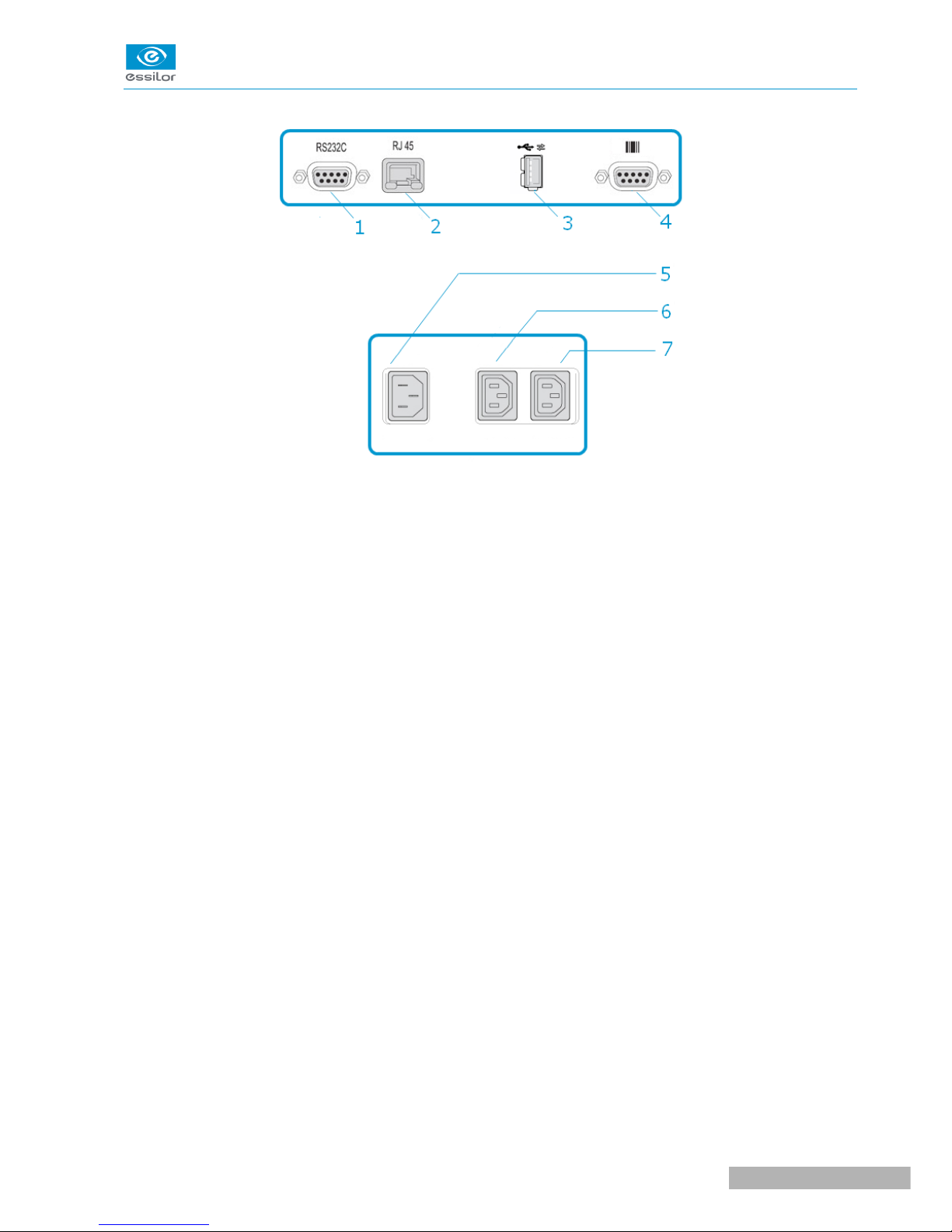
Connectors
1. Serial port
2. Ethernet port
3. USB port
4. Barcode reader port
5. Power socket
6. Solenoid valve socket
7. Pump socket (tank + pump) / Solenoid valve socket (town)
Accessories
Transport wedges to be kept
Use accessories
• 22 mm posiblock holder
• 18x14 mm posiblock holder
• 22 mm stop
• 18x14 mm stop
• Unblocking clamp
• Ø 1.0 mm drill bit (mounted on the module) (option)
• Ø 0.8 mm drill bit (option)
• Ø 25 mm grooving wheel (mounted on the module)
• Chamfering wheel (mounted on the module)
Servicing accessories
• Orange dressing stone for glass roughing wheel
• White dressing stone for finishing wheel
• Square dressing stone for polishing wheel
• Drill bit changeover tool
• Open-ended spanners for tool changeover (quantity 2)
USER MANUAL> I. FIRST STEPS
9
Neksia > v1.0 - 02.14
Page 10

Options
• Trimaterial edger for chamfering glass lenses
• Barcode reader
• Roll of barcode labels
• Open or closed circuit spraying kit
Connection accessories
• Power cable
• RJ45 cable for the tracer-edger connection
• Wastewater evacuation pipe with attachment ring
2. USING THE EDGER
In this section, you will find all the information concerning the following:
• Turning the edger on (F p.10) and off (F p.10)
• The use of the touch screen and the keyboards (F p.11),
• The description of the work screens of the edger (F p.12).
a. Turning on the edger
To switch on the edger, press the main switch located on the top of the machine.
The edger will initialise.
On the edger screen, press the icon to complete the initialization phase.
A beep indicates that the initialisation was successful.
The edger is ready for use when the initial screen is displayed.
b. Switching off off the edger
Before switching off the edger:
• check that there is no lens in the trough
• check that the lens clamp shafts are loosened and that the trough door is open
• select the edging screen
Select then .
A confirmation message is displayed on each screen.
Select to confirm.
The edger will switch off.
Neksia > v1.0 - 02.14
10
USER MANUAL> I. FIRST STEPS
>
>
>
>
1
2
1
2
3
Page 11
Extended period of non-use
For a prolonged period of non-use (a few days), it is preferable to turn off the edger using the main
switch.
c. Using the touch screen and keypads
Using the touch screen
Use the stylus delivered with the tracer-centerer-blocker on the touch screen.
You can also touch the screen with your finger.
• If the response area does not correspond to the position of the key, you need to calibrate the touch
screen. For further information, refer to the section Maintenance and servicing > Check and calibrate
> Calibrate the touch screen (F p.59).
• Never press hard on the screen as this could break it.
• Never press on the screen with sharp objects such as pens, scissors, clamps, etc.
• Screen breakage is not covered by the guarantee.
On each screen, press the icon-buttons to access the desired menus and functions.
Using the keypads
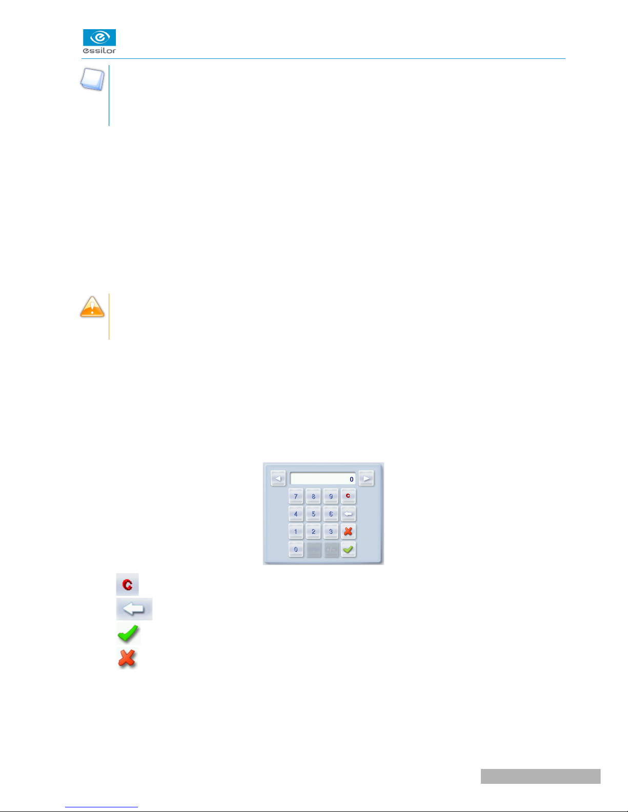
When you need to input or modify data, two types of keypads are automatically displayed, according to the
information to be input.
• The numeric keypad is displayed for the input of values.
• Reset the fields
• Back
• Confirm
• Cancel and go back to the work screen
• The alphanumeric keyboard is displayed for storing, calling and searching for jobs.
USER MANUAL> I. FIRST STEPS
11
Neksia > v1.0 - 02.14
Page 12
• Job&ID
&
• Job reference (alphanumeric characters)
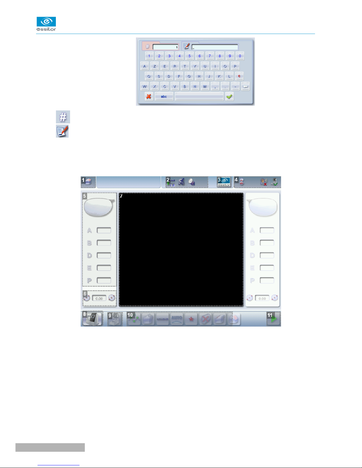
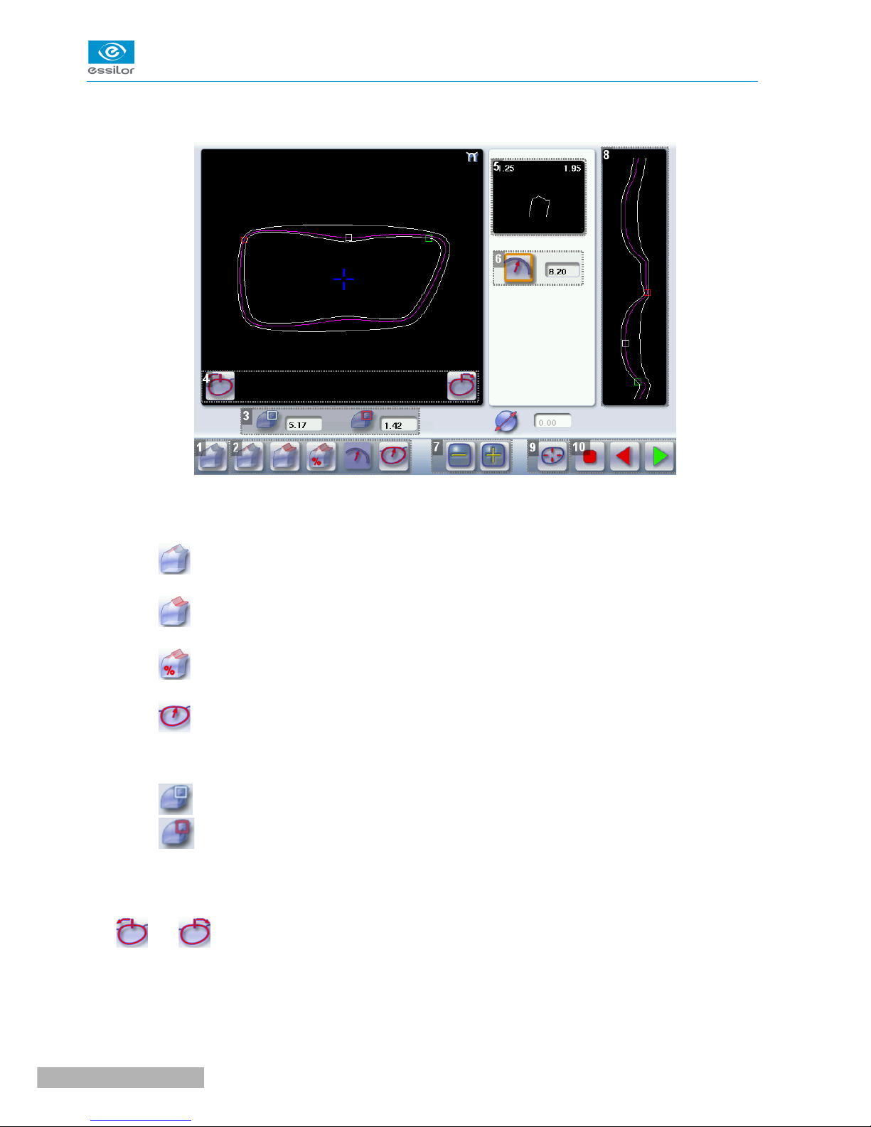
d. Edging screen
Main menus of the edging screen:
1. Work screen indicator
2. Tool wear indicators
3. Settings
4. Devices connected
5. Active eye and information on the shape
6. Size increase / reduction
7. Work area
8. Machine shutdown.
Neksia > v1.0 - 02.14
12
USER MANUAL> I. FIRST STEPS
Page 13

9. Job call
10. Actions available for the current screen
11. Start the edging cycle
Detailed functions
For more information, consult the section Edging a lens > Work environment of the edger > Captioned
screen. (F p.16)
USER MANUAL> I. FIRST STEPS
13
Neksia > v1.0 - 02.14
Page 14

Neksia > v1.0 - 02.14
14
USER MANUAL> I. FIRST STEPS
Page 15

II. EDGING A LENS
Page 16

This chapter describes the procedures for edging all types of lens:
• Beveling (F p.20)
• Grooving (F p.27)
• Flat-edge finishing (F p.35)
• Drilled job (F p.36)
• Polishing (F p.39)
• Chamfering (F p.40)
• Do a Retouching (F p.42)
1. EDGER WORKING ENVIRONMENT
This section describes:
• The edger work screen (F p.16)
• Shape call-up procedure (F p.18)
• Putting the lens in place (F p.19)
a. Menu screen
1. Size reduction / increase (mm)
2. Job call button from the tracer
3. Lens material
◦ Plastic lens - index 1.5
&
◦ Polycarbonate lens
◦ Medium/High index plastic lens - index > 1.5
Neksia > v1.0 - 02.14
16
USER MANUAL> II. EDGING A LENS
Page 17
◦ Trivex lens
TM
◦ Glass lens
◦ Tribrid lens
TM
The configuration of the edging cycles depends on the type of material. An incorrect choice may result in
material damage.
4. Type of finish
◦ Bevel
◦ Groove
◦ Flat-edge
5. Drilling
◦ Drilling enabled
◦ Drilling disabled
6. Edging mode
◦ Automatic mode
The finish parameters are automatically calculated according to the information acquired when
tracing the frame and feeling the lens.
◦ Customized mode
The finish settings can be fully customized.
7. Type of cycle
◦ Standard cycle
For all types of materials.
◦ 2-star cycle
For all types of materials. This cycle offers a more sophisticated edging mode than the standard
cycle, dedicated to thin lenses or hydrophobic lenses.
8. Polishing
◦ Polished lens
◦ Non-polished lens
9. Front surface chamfering
◦ Thin chamfer
◦ Thick chamfer
◦ No chamfering
10. Rear surface chamfering
USER MANUAL> II. EDGING A LENS
17
Neksia > v1.0 - 02.14
Page 18
◦ Thin chamfer
◦ Thick chamfer
◦ No chamfering
11. Manual lens clamping
Press and hold to close the lens clamp shafts manually.
12. Start the edging cycle
The door closing and lens clamping are automatic.
Always browse from left to right: depending on your selection, certain menus will be available while
others will not.
Your habits taken into account
The edger memorises your working habits: as time goes by, the buttons of the functions you use most
often will be displayed by default.
b. Calling a shape
There are 3 ways of calling the shape you want to edge:
• Calling the current job:
> Press to display the shape being processed on the tracer.
• Calling the number of a shape saved on the tracer:
> Press for a few seconds on to open the numeric keypad.
> You can then call a shape via the ID allocated to it.
• Job call via a barcode:
> Scan the barcode using the barcode reader (optional).
Always block your two lenses before proceeding with the edging. If a job in the course of modification on the
tracer (display of the symbol beside the reference) is called on the edger, a warning message is
displayed.
> Press to continue and display the job on the edger. The modifications underway are then ignored.
> Press to prevent the display of the job and finish the modifications underway on the tracer.
A reminder of the type of posiblock required is displayed on the shape. It is crucial to use the proper
accessory to edge the lens. Otherwise, an error message is displayed at the start of the cycle.
Neksia > v1.0 - 02.14
18
USER MANUAL> II. EDGING A LENS
Page 19
c. Lens set-up and feeling
Prerequisite: the lens must be centered and blocked before placing it in the edger.
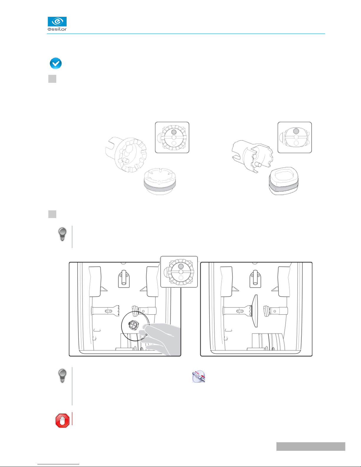
Check that the posiblock holder and the stop correspond to the posiblock used. Otherwise, you will need
to remove them form the lens clamp shafts and replace them with the tools matching the diameter of the
posiblock.
• For a 22 mm posiblock • For an 18×14 mm posiblock
Place the lens in the posiblock holder.
Place the metal peg of the posiblock upwards and the positioner downwards: a magnet is used to
hold the lens in position on the axis.
You can clamp the lens manually by pressing : Manual lens clamping is particularly suited to
hydrophobic lenses, thick lenses and high-camber lenses, as it ensures that the lens won't come
off the pad before clamping.
Make sure you move your hand well away before you start the edging cycle.
USER MANUAL> II. EDGING A LENS
19
Neksia > v1.0 - 02.14
1
2
Page 20
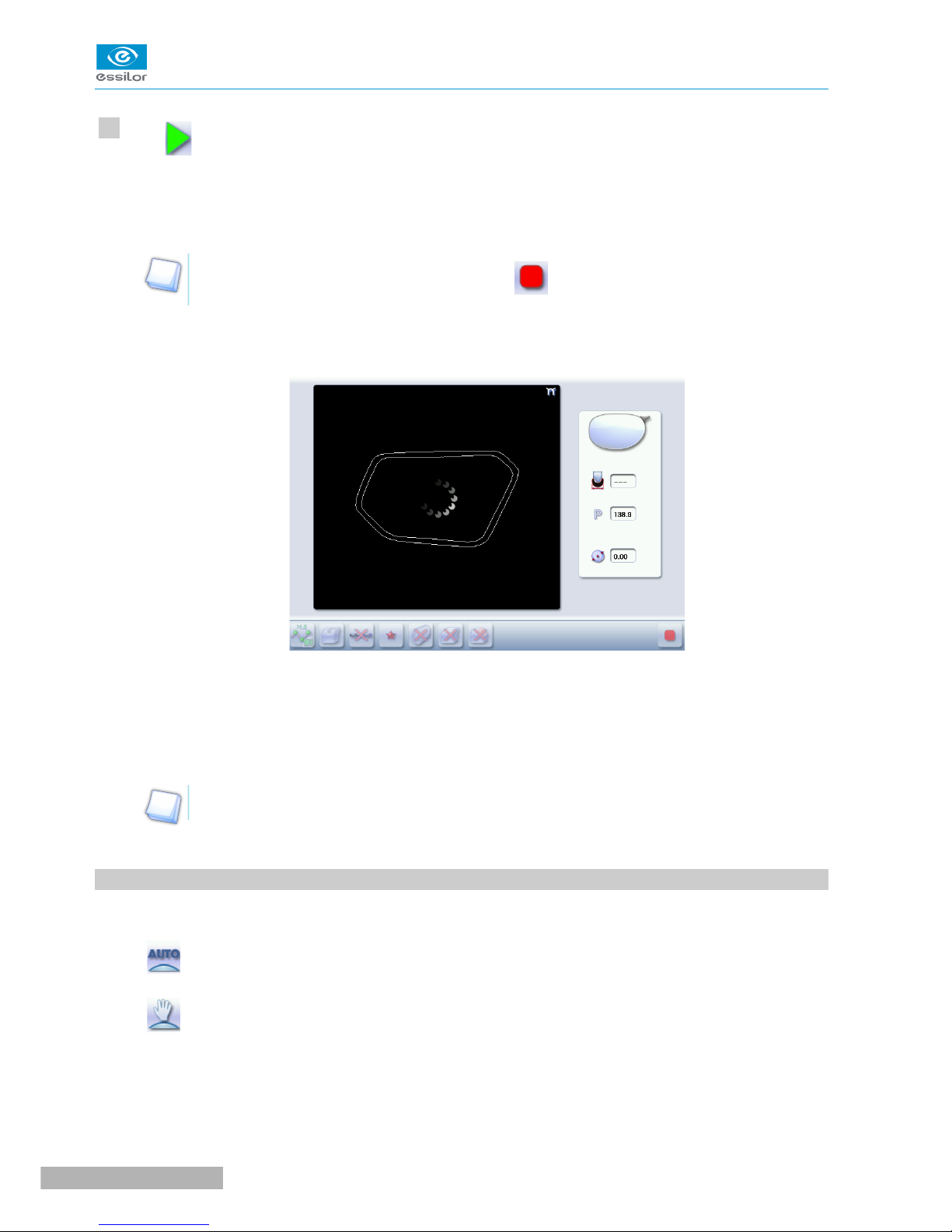
Press .
The door closes then the lens clamping operation starts.
The size of the posiblock holder is checked then the feeling cycle starts.
To interrupt the feeling cycle at any time, press .
As the lens is felt, its shape appears on screen. The double tracing represents the profile of the front
surface of the shape (inner shape) and its rear surface (outer shape).
In the case of edging mode selection:
• automatic, you do not have anything to configure, all the data is automatically recovered from
the tracer. The lens edging starts automatically after the feeling cycle.
• customized, the finish parameters can be fully customized.
For further information, refer to the section concerning your type of finish.
2. BEVELING
This section describes the procedures for creation of a bevel:
• In automatic mode (F p.21), you do not have anything to configure. All the data is automatically
retrieved from the tracer. The lens edging starts automatically after the feeling cycle.
• In customized mode (F p.22), you can opt for front/rear surface tracking, a distributed bevel, lens
curve tracking or rim tracking. You can also do the following:
◦ a total modification of the bevel curve (F p.25)
◦ a modification at a point of the bevel curve (F p.26)
◦ a displacement of the bevel curve (F p.27)
• You can consult the description of the customized bevel screen. (F p.22)
Neksia > v1.0 - 02.14
20
USER MANUAL> II. EDGING A LENS
>
>
>
>
3
Page 21
a. Automatic beveling
Call the desired shape located on the tracer.
The shape is displayed on the edger work screen.
After the tracing of a rimmed frame:
• The bevel finish is selected by default.
• The automatic mode is selected by default.
Select lens material.
Select the type of cycle.
Choose whether or not to polish and/or chamfer your lens.
For more information, refer to the section Edging a lens > Polishing (F p.39)and Edging a lens >
Chamfering (F p.40).
Press .
The door closes, the lens is clamped, then the feeling operation starts.
The edging cycle starts.
When the edging cycle is finished, the retouch screen is displayed.
Press to release the lens.
If necessary, retouch the lens.
Otherwise, start edging the second lens. Select the lens directly on screen, on the left or right of the
work area.
The edging screen for the second lens is displayed. All finishes chosen and the modifications made
are kept.
USER MANUAL> II. EDGING A LENS
21
Neksia > v1.0 - 02.14
>
>
>
>
>
>
1
2
3
4
5
6
7
Page 22
b. Legend screen for customized bevels
1. Automatic bevel
2. Customized bevels
◦ Front surface tracking: the crest of the bevel is positioned at a constant distance from the
front surface.
◦ Rear surface tracking: the crest of the bevel is positioned at a constant distance from the
rear surface.
◦ Distributed bevel: the position of the crest of the bevel is proportional to the thickness of
the lens, with respect to the front surface.
◦ Frame rim tracking: the bevel tracks the groove precisely, according to the data obtained
on frame tracing.
3. Lens thickness
◦ Maximum lens thickness - represented by the white square along the shape.
◦ Minimum lens thickness - represented by the red square along the shape.
4. Cursor movement
The cursor is represented by the green square along the shape. To move it, select it directly or use the
and buttons.
5. Zoom window
Represents the bevel profile and indicates the distance between the bevel crest and the front and rear
surfaces of the lens at the cursor position.
Neksia > v1.0 - 02.14
22
USER MANUAL> II. EDGING A LENS
Page 23
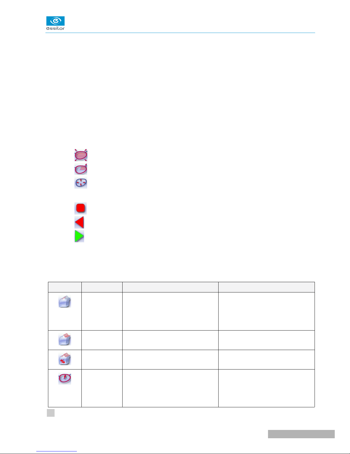
6. Bevel distribution value
Distribution value modifiable for:
◦ front/rear surface tracking
◦ a distributed bevel
◦ lens curve tracking
7. Modify the selected value
Reduce or increase the distribution value.
8. Bevel trajectory
Flat representation of the lens making it possible to assess the distances between the bevel crest and the
front & rear surfaces of the lens.
9. Trajectory modification
◦ General modification of the bevel curve
◦ Modification of the bevel curve at a particular point
◦ Displacement of the bevel curve
10. Navigation
◦ Stop the cycle
◦ Back to the main edging screen
◦ Start the edging cycle
c. Customized beveling
The use of the customized bevel depends on 2 parameters: the frame and the lens. Before starting your job,
identify the major constraint.
BEVEL FRAME LENS ADVANTAGES
Classic Lens for which the front surface base
is approximately equal to the frame
base.
Makes it possible to do an
aesthetically pleasing job. The lens
material does not protrude beyond
the front of the frame.
Classic Lenticular lens&, Executive lens
&
Makes it possible to do a job with
specific lenses.
Classic Thin lens Makes it possible to balance out the
bevel when thin lenses are used.
Particular
groove (groove
with
meniscus&)
Thin lens for which the base is
approximately equal to the meniscus
of the groove.
Compliance with original shape.
Job using a specific frame.
Call the desired shape located on the tracer.
USER MANUAL> II. EDGING A LENS
23
Neksia > v1.0 - 02.14
1
Page 24
The shape is displayed on the edger work screen.
After the tracing of a rimmed frame:
• The bevel finish is selected by default.
• The automatic mode is selected by default.
Select lens material.
Change the edging mode. Press to select customized mode .
Select the type of cycle.
Choose whether or not to polish and/or chamfer your lens.
For more information, refer to the section Edging a lens > Polishing (F p.39)and Edging a lens >
Chamfering (F p.40).
Press .
The door closes, the lens is clamped and then felt.
The customized bevel finish screen is displayed.
Select the type of customized bevel you want to do.
To avoid reproducing defects when tracking a frame rim, check that the frame groove is in perfect
condition and that the hinges are properly closed. All groove imperfections will be reproduced.
Press and to adjust the distribution value if required.
Press .
The edging cycle starts.
When the edging cycle is finished, the retouch screen is displayed.
Press to release the lens.
Neksia > v1.0 - 02.14
24
USER MANUAL> II. EDGING A LENS
>
>
>
>
>
>
2
3
4
5
6
7
8
9
10
Page 25
If necessary, retouch the lens.
Otherwise, start edging the second lens. Select the lens directly on screen, on the left or right of the
work area.
The edging screen for the second lens is displayed. All finishes chosen and the modifications made
are kept.
d. Modifying the bevel curve
Once you have configured the desired type of customized bevel, you can complete your customization by
moving the bevel curve towards the front or rear surface of the lens so it takes on its shape.
Press from the customized bevel finish screen.
You will access the trajectory modification screen.
Press to select the general modification of the bevel curve.
Use the buttons and to move the bevel curve:
• Press to move the curve towards the front surface of the lens.
• Press to move the curve towards the rear surface of the lens.
The curve cannot be moved more than the minimum distance between the front and rear surfaces
observed on the bevel before the modification.
The position of the bevel as well as the distances between the crest of the bevel and the front and
rear surfaces of the lens are displayed in the zoom window at the position of the cursor.
Press .
The edging cycle starts.
When the edging cycle is finished, the retouch screen is displayed.
Press to release the lens.
If necessary, retouch the lens.
USER MANUAL> II. EDGING A LENS
25
Neksia > v1.0 - 02.14
>
>
>
>
>
11
1
2
3
4
5
6
Page 26
Otherwise, start edging the second lens. Select the lens directly on screen, on the left or right of the
work area.
The edging screen for the second lens is displayed. All finishes chosen and the modifications made
are kept.
e. Modifying the bevel curve at a particular point
Once you have configured the desired type of customized bevel, you can complete your customization by
partially moving the bevel curve towards the front or rear surface of the lens so it takes on its shape.
Press from the customized bevel finish screen.
You will access the trajectory modification screen.
Press to select modification of the bevel curve at a particular point.
Using the cursor, select the point on the curve that you want to move or click directly on the position of
the shape you want to modify.
Use the buttons and to move the point on the selected curve.
• Press to move it towards the front surface of the lens.
• Press to move it towards the rear surface of the lens.
The curve cannot be moved more than the minimum distance between the front and rear surfaces
observed on the bevel before the modification.
The position of the bevel as well as the distances between the crest of the bevel and the front and
rear surfaces of the lens are displayed in the zoom window at the position of the cursor.
Press .
Press to go back to the customized bevel finish screen.
For the second lens, the customized bevel icon is pre-selected and the trajectory modification icon is
displayed.
Neksia > v1.0 - 02.14
26
USER MANUAL> II. EDGING A LENS
>
>
>
>
1
2
3
4
5
Page 27

f. Displacing the bevel curve
The displacement of the bevel curve makes it possible to move the bevel without modifying its curve.
Press from the customized bevel finish screen.
You will access the trajectory modification screen.
Press to select the displacement of the bevel curve.
Use the and buttons to displace the bevel curve:
• Press to displace it towards the front surface of the lens.
• Press to displace it towards the rear surface of the lens.
The position of the bevel as well as the distances between the crest of the bevel and the front and
rear surfaces of the lens are displayed in the zoom window at the position of the cursor.
Press .
The edging cycle starts.
When the edging cycle is finished, the retouch screen is displayed.
Press to release the lens.
If necessary, retouch the lens.
Otherwise, start edging the second lens. Select the lens directly on screen, on the left or right of the
work area.
The edging screen for the second lens is displayed. All finishes chosen and the modifications made
are kept.
3. GROOVING
This section describes the procedures for the creation of a groove:
• In automatic mode (F p.28), you do not have anything to configure. All the data is automatically
retrieved from the tracer. The lens cutting starts automatically after the feeling cycle.
USER MANUAL> II. EDGING A LENS
27
Neksia > v1.0 - 02.14
>
>
>
>
>
1
2
3
4
5
6
Page 28

• In customized mode (F p.31), you can carry out a front/rear surface tracking, a distributed
groove or a lens curve tracking. You can also do the following:
◦ a general modification of the groove curve (F p.32)
◦ a modification at a point of the groove curve (F p.33)
◦ a displacement of the groove curve (F p.34)
• You can consult the description of the customized groove screen (F p.29).
In certain cases, the lens base or thickness makes grooving impossible.
> An error message is displayed.
> The white central line becomes red on the entire contour of the lens.
a. Automatic grooving
Call the desired shape located on the tracer.
The shape is displayed on the edger work screen.
After tracing a pattern, demo lens or recut lens, without any drilling settings:
• the groove finish is selected by default.
• automatic mode is selected by default.
Select lens material.
Select the type of cycle.
Choose whether or not to polish and/or chamfer your lens.
For more information, refer to the section Edging a lens > Polishing (F p.39)and Edging a lens >
Chamfering (F p.40).
Press .
The door closes, the lens is clamped and then felt.
The edging cycle starts.
When the edging cycle is finished, the retouch screen is displayed.
Press to release the lens.
If necessary, retouch the lens.
Neksia > v1.0 - 02.14
28
USER MANUAL> II. EDGING A LENS
>
>
>
>
>
1
2
3
4
5
6
7
Page 29

Otherwise, start edging the second lens. Select the lens directly on screen, on the left or right of the
work area.
The edging screen for the second lens is displayed. All finishes chosen and the modifications made
are kept.
b. Customized groove menu screen
1. Automatic groove
2. Customized grooves
◦ Front surface tracking: the middle of the groove is positioned at a constant distance from
the front surface.
◦ Rear surface tracking: the middle of the groove is positioned at a constant distance from
the rear surface.
◦ Distributed groove: the middle of the groove is positioned in proportion to the thickness of
the lens, with respect to the front surface.
◦ Lens curve tracking: the camber of the groove is adjustable.
3. Lens thickness
◦ Maximum lens thickness - represented by the white square along the shape
◦ Minimum lens thickness - represented by the red square along the shape
4. Cursor movement
USER MANUAL> II. EDGING A LENS
29
Neksia > v1.0 - 02.14
>
Page 30

The cursor is represented by the green square along the shape. To move it, select it directly or use the
and buttons.
5. Zoom window
Distance between the edges of the groove and the front & rear surfaces of the lens at the position of the
cursor.
6. Groove settings
◦ Distribution value - according to the type of customized groove selected
◦ Groove depth (in mm)
◦ Groove width (in mm)
7. Modify the selected setting
8. Groove trajectory
Flat representation of the lens making it possible to measure the distances between the groove and the
front & rear surfaces of the lens.
9. Modify the trajectory
◦ General modification of the groove curve
◦ Modification of a point in the groove curve
◦ Displacement of the groove curve
10. Navigation
◦ Stop the cycle
◦ Back to the main edging screen
◦ Start the edging cycle
Neksia > v1.0 - 02.14
30
USER MANUAL> II. EDGING A LENS
Page 31

c. Customized grooving
The use of the customized groove depends on 2 parameters: the frame and the lens. Before starting your
job, identify the major constraint.
GROOVE FRAME LENS ADVANTAGES
Standard groove Lens for which the front surface base
is approximately equal to the frame
base.
Makes it possible to do an
aesthetically pleasing job. The lens
material does not protrude beyond
the front of the frame.
Standard groove Lens for which the rear surface base
is not as high as the front surface
base.
Minimises the risks of the nylon
thread coming out.
Standard groove Thin lens Makes it possible to balance out the
groove when thin lenses are used.
Flat base
High base
Thin lens for which the base is
approximately equal to the frame
base.
In the event of pattern tracing (base
= 0), makes it possible to retrieve
the frame base.
Call the desired shape located on the tracer.
The shape is displayed on the edger work screen.
After tracing a pattern, demo lens or recut lens, without any drilling settings:
• the groove finish is selected by default.
• automatic mode is selected by default.
Select lens material.
Change the edging mode. Press to select customized mode .
Choose the type of cycle.
Choose whether or not to polish and/or chamfer your lens.
For more information, refer to the section Edging a lens > Polishing (F p.39)and Edging a lens >
Chamfering (F p.40).
Press .
USER MANUAL> II. EDGING A LENS
31
Neksia > v1.0 - 02.14
>
>
1
2
3
4
5
6
Page 32

The door closes, the lens is clamped and then felt.
The customized groove finish screen is displayed.
Select the type of customized groove you want to do.
Select the values you want to modify and press and to adjust them if necessary
Press .
The edging cycle starts.
When the edging cycle is finished, the retouch screen is displayed.
Press to release the lens.
If necessary, retouch the lens.
Otherwise, start edging the second lens. Select the lens directly on screen, on the left or right of the
work area.
The edging screen for the second lens is displayed. All finishes chosen and the modifications made
are kept.
d. Modifying the groove curve
Once you have configured the desired type of customized groove, you can complete your customization by
moving the groove curve towards the front or rear surface of the lens so it takes on its shape.
Press from the customized groove finish screen.
You will access the trajectory modification screen.
Press to select the general modification of the groove curve.
Use the buttons and to move the groove curve.
• Press to move the curve towards the front surface of the lens.
Neksia > v1.0 - 02.14
32
USER MANUAL> II. EDGING A LENS
>
>
>
>
>
>
7
8
9
10
11
1
2
3
Page 33

• Press to move the curve towards the rear surface of the lens.
The curve cannot be moved more than the minimum distance between the front and rear surfaces
observed on the groove before the modification.
The position of the groove as well as the distances between the center of the groove and the front &
rear surfaces of the lens are displayed in the zoom window.
Press .
The edging cycle starts.
When the edging cycle is finished, the retouch screen is displayed.
Press to release the lens.
If necessary, retouch the lens.
Otherwise, start edging the second lens. Select the lens directly on screen, on the left or right of the
work area.
The edging screen for the second lens is displayed. All finishes chosen and the modifications made
are kept.
e. Modifying a point in the groove curve
Once you have configured the desired type of customized groove, you can complete your customization by
moving the groove curve towards the front or rear surface of the lens so it takes on its shape.
Press from the customized groove finish screen.
You will access the trajectory modification screen.
Press to select modification of a point in the groove curve.
Using the cursor, select the point on the curve that you want to move or click directly on the screen.
Use the buttons and to move the point on the selected curve.
• Press to move it towards the front surface of the lens.
USER MANUAL> II. EDGING A LENS
33
Neksia > v1.0 - 02.14
>
>
>
>
>
4
5
6
1
2
3
4
Page 34

• Press to move it towards the rear surface of the lens.
The curve cannot be moved more than the minimum distance between the front and rear surfaces
observed on the groove before the modification.
The position of the groove as well as the distances between the center of the groove and the front &
rear surfaces of the lens are displayed in the zoom window.
Press .
Press to go back to the customized bevel finish screen.
For the second lens, the customized groove icon is pre-selected and the trajectory modification icon
is displayed.
f. Displacement of the groove curve
The displacement of the groove curve enables you to move the groove without modifying its curve or
perimeter.
Press from the customized groove finish screen.
You will access the trajectory modification screen.
Press to select the displacement of the curve.
Use the and buttons to displace the curve.
• Press to displace it towards the front surface of the lens.
• Press to displace it towards the rear surface of the lens.
The position of the groove as well as the distances between the center of the groove and the front &
rear surfaces of the lens are displayed in the zoom window.
Press .
The edging cycle starts.
When the edging cycle is finished, the retouch screen is displayed.
Neksia > v1.0 - 02.14
34
USER MANUAL> II. EDGING A LENS
>
>
>
>
>
>
5
1
2
3
4
Page 35

Press to release the lens.
If necessary, retouch the lens.
Otherwise, start edging the second lens. Select the lens directly on screen, on the left or right of the
work area.
The edging screen for the second lens is displayed. All finishes chosen and the modifications made
are kept.
4. FLAT-EDGE FINISHING
For a flat-edge finish, only automatic mode is accessible.
Call the desired shape located on the tracer.
The shape is displayed on the edger work screen.
Select lens material.
Press to select the flat-edge finish.
Choose the type of cycle.
Choose whether or not to polish and/or chamfer your lens.
For more information, refer to the section Edging a lens > Polishing (F p.39) and Edging a lens >
Chamfering (F p.40).
Press .
The door closes, the lens is clamped and then felt.
The edging cycle starts.
When the edging cycle is finished, the retouch screen is displayed.
Press to release the lens.
USER MANUAL> II. EDGING A LENS
35
Neksia > v1.0 - 02.14
>
>
>
>
>
5
6
1
2
3
4
5
6
7
Page 36

If necessary, retouch the lens.
Otherwise, start edging the second lens. Select the lens directly on screen, on the left or right of the
work area.
The edging screen for the second lens is displayed. All finishes chosen and the modifications made
are kept.
5. DRILLED JOB
Prerequisite: the edger's drilling function is only accessible if the tracer sends a shape with drilling
settings. For more information, consult the chapter Preparing a drilled job in the tracer manual.
You can do the drilling in automatic mode or in customized mode:
• In automatic mode (F p.36), you do not have anything to configure. The drilling angle consists of
the average value calculated at right angles with the front surface of the lens for each drilling point.
The lens edging starts automatically after the feeling cycle.
• In customized mode (F p.38), you can do the following:
◦ Drilling at right angles with the front or rear surface: you can modify the diameter but not the
drilling angle which is automatically calculated by the edger based on the lens curve.
◦ Customized drilling: you can modify the diameter and angle for each drilling point.
• You can consult the description of the customized drilling screen (F p.37).
Two different diameter drill bits are available: a 1 mm bit and a 0.8 mm bit. If the diameter of the drilling
point is smaller than that of the installed drill bit, an error message is displayed. Change the drill bit or
modify the diameter of the drilling points.
a. Automatic drilling
Call the desired shape located on the tracer.
The shape is displayed on the edger work screen.
After the tracing of a shape with drilling settings:
• The drilling function is selected by default.
• The automatic mode is selected by default.
Select lens material.
Select the type of finish.
Select the type of cycle.
Choose whether or not to polish and/or chamfer your lens.
Neksia > v1.0 - 02.14
36
USER MANUAL> II. EDGING A LENS
>
>
>
8
1
2
3
4
5
Page 37

For more information, refer to the section Edging a lens > Polishing (F p.39) and Edging a lens >
Chamfering (F p.40).
Press .
The door closes, the lens is clamped and then felt.
The edging cycle starts.
When the edging cycle is finished, the retouch screen is displayed.
Press to release the lens.
If necessary, retouch the lens.
Otherwise, start edging the second lens. Select the lens directly on screen, on the left or right of the
work area.
The edging screen for the second lens is displayed. All finishes chosen and the modifications made
are kept.
b. Customized drilling menu screen
1. Type of drilling
◦ Perpendicular to the front surface
◦ Perpendicular to the rear surface
USER MANUAL> II. EDGING A LENS
37
Neksia > v1.0 - 02.14
>
>
>
>
6
7
8
Page 38

◦ Customized
2. Select the drilling points
◦ Nasal side
◦ Temporal side
◦ All drilling points
3. Modify the selected value
4. Modify the diameter
◦ diameter (mm)
◦ difference between the initial value and the modified value
5. Modify the drilling angle
◦ drilling angle (degrees)
◦ difference between the initial value and the modified value
6. Cross-sectional view
Cross-sectional view of the lens after the feeling cycle, showing the angle of the drill bit at the selected
drilling point.
7. Reminder of size reduction / increase applied to lens diameter
8. Navigation
◦ Stop the cycle
◦ Return to the main edging screen without saving your changes
◦ Start the cycle
c. Customized drilling
Call the desired shape located on the tracer.
The shape is displayed on the edger work screen.
After the tracing of a shape with drilling settings:
• The drilling function is selected by default.
• The automatic mode is selected by default.
Select lens material.
Change the edging mode. Press to select customized mode .
Neksia > v1.0 - 02.14
38
USER MANUAL> II. EDGING A LENS
>
>
1
2
3
Page 39

Choose the type of cycle.
Choose whether or not to polish and/or chamfer your lens.
For more information, refer to the section Edging a lens > Polishing (F p.39) and Edging a lens >
Chamfering (F p.40).
Press .
The feeling cycle starts.
The customized drilling screen is displayed.
Select the type of drilling you want to do.
If necessary, select the drilling point(s) you want to modify.
If necessary, modify the diameter and/or angle of the selected drilling point.
The difference between the initial value and the modified one is displayed in the delta column.
Press .
The edging cycle starts.
When the edging cycle is finished, the retouch screen is displayed.
Press to release the lens.
If necessary, retouch the lens.
Otherwise, start edging the second lens. Select the lens directly on screen, on the left or right of the
work area.
The edging screen for the second lens is displayed. All finishes chosen and the modifications made
are kept.
6. POLISHING
USER MANUAL> II. EDGING A LENS
39
Neksia > v1.0 - 02.14
>
>
>
>
>
>
4
5
6
7
8
9
10
11
12
Page 40

Press the button to activate/deactivate polishing.
LENS MATERIAL AVAILABLE OPTIONS
The polishing option is pre-selected and is strongly recommended by the manufacturer to
prevent small cracks.
Make sure you select the correct type of material for MHI (> 1.5) or Tribrid lenses and
never polish a lens of this type without water. Otherwise, the polishing wheel could suffer
irreversible damage.
The polishing option is pre-selected.
The polishing option is not available for high-base jobs. However, the high-base wheel has been
designed to provide an equivalent finish on polycarbonate lenses.
7. CHAMFERING
The chamfer, also called counter-bevel, removes the sharp edge of the lens.
• Standard value of a small chamfer: 0.20 mm
• Standard value of a large chamfer: 0.40 mm
Neksia > v1.0 - 02.14
40
USER MANUAL> II. EDGING A LENS
Page 41

Before you select a type of chamfer, make sure it is compatible with the lens characteristics:
• Lens material
LENS MATERIAL AVAILABLE OPTIONS
The quality of the chamfer depends on the spraying. Make sure there is a constant
flow of water until the end of the chamfering operation.
The chamfering wheel supplied cannot be used on glass lenses. For further
information, contact your technical department.
• Thickness at the edge of the lens
LENS THICKNESS AVAILABLE OPTIONS
> 1.2 mm
between 1 and 1. 2
mm
< 1 mm
• Distance between the edge of the groove and the edge of the lens
DISTANCE AVAILABLE OPTIONS
> 0.8 mm
between 0.5 and 0.8
mm
< 0.5 mm
The chamfers available also depend on the lens shape and the posiblock used when blocking.
Press the and buttons to configure a thin chamfer, a thick chamfer or no chamfer on the front
and rear surfaces of the lens.
USER MANUAL> II. EDGING A LENS
41
Neksia > v1.0 - 02.14
Page 42

8. RETOUCHING
1. Diameter modification
2. Manual lens clamping
3. Start the retouch
Neksia > v1.0 - 02.14
42
USER MANUAL> II. EDGING A LENS
Page 43

Differences with the edging screen
The edging screen is different to the retouch
screen through:
• the presence of the posiblock
• no frame thickness
• the edging start-up button
When the first-lens edging cycle is finished:
Press to release the lens.
Proceed to lens assembly and check that edging was correctly configured.
Depending on your job:
• If your job is perfect, proceed with the machining of your second lens.
> All of the selected finishing options and modifications made are kept.
• If the lens requires adjustment, do a retouch on the edged lens to obtain optimal results.
Indicate the size reduction to be applied to the lens you want to retouch.
The chosen finish and the modifications made during the edging cycle are automatically selected.
Insert the lens in the posiblock holder.
To close the clamp shafts manually, press and hold .
Press .
For a customized finish, the customized finish screen is displayed.
In all other cases, the door closes, the lens is clamped automatically, then the retouching starts.
Select the second lens to be edged directly on screen, on the left or right of the work area.
The edging screen for the second lens is displayed.
USER MANUAL> II. EDGING A LENS
43
Neksia > v1.0 - 02.14
>
>
>
>
>
1
2
3
4
5
6
Page 44

All finishes chosen and the modifications made are kept. The retouch done on the first lens is
automatically saved for the edging of the second lens.
Neksia > v1.0 - 02.14
44
USER MANUAL> II. EDGING A LENS
>
Page 45

USER MANUAL> II. EDGING A LENS
45
Neksia > v1.0 - 02.14
Page 46

Page 47

III. CONFIGURING THE EDGER
Page 48

This chapter explains how to configure the edger according to your requirements. You can:
• configuring the edger (F p.48) (time, date, language, connections, screen-saver)
• adjusting the precision of the edger (F p.50),
• restoring the factory settings (F p.54)
1. CONFIGURE THE EDGER
This section describes the procedures to:
• set the time, date and language (F p.48)
• access the connections and the network (F p.49)
• configure a screensaver and the brightness of the screen (F p.49).
a. Time, date and language
To access this menu from your work screen, select > > .
The following screen is displayed:
1. Time
Use the and arrows to set the time.
2. Date
Use the and arrows to set the date.
3. Type of date display
Select the type of display out of the available formats.
4. Language
Neksia > v1.0 - 02.14
48
USER MANUAL> III. CONFIGURING THE EDGER
Page 49

Select the flag corresponding to your language.
5. Other languages
Press to display the other languages.
6. Confirm
Press to save the new configuration.
Once the setting has been completed:
1. Press to save.
2. Press to return to the work screen.
b. Connections
Connections are configured from the tracer (see the instructions for use of the tracer). The screen which you
access from the edger is only available for consultation purposes.
c. Screensaver and screen brightness
This menu is used to configure a screensaver and the brightness of the work area.
To access this menu from your work screen, select > > .
The following screen is displayed:
USER MANUAL> III. CONFIGURING THE EDGER
49
Neksia > v1.0 - 02.14
Page 50

1. Screensaver display
Activate or deactivate the screensaver.
2. Triggering
Set the waiting time before the display of the screensaver (in seconds).
3. Transition
Set the transition time between each image (in seconds).
4. Adjusting the default brightness of the screen
Once the change has been made, press to return to the work screen.
2. ADJUSTING THE PRECISION OF THE EDGER
This menu enables you to adjust the precision of the edger. You can adjust:
• the diameter of the finished lenses (F p.50)
• the position of the bevel and groove (F p.51)
• the diameter of drill holes (F p.52)
• the chamfer (F p.53)
• the depth and width of the groove (F p.54)
a. Adjusting the diameter of the finished lenses
If lenses of a particular material always seem too small or too big after edging, you can adjust their diameter
according to the type of frame.
To access that menu from your edger work screen, select > > .
The following screen is displayed:
1. Frame types
Neksia > v1.0 - 02.14
50
USER MANUAL> III. CONFIGURING THE EDGER
Page 51

◦ Metal
◦ Plastic
◦ Optyl
◦ Drilled / Grooved / Flat
2. Lens materials
◦ Plastic
◦ Polycarbonate
◦ MHI
◦ Trivex
TM
◦ Glass
◦ Tribrid
TM
3. Adjust the lens diameter
a. Press the value to be modified.
> The numeric keypad is displayed.
b. Enter the new value.
◦ Negative value: the diameter will be smaller
◦ Positive value: the diameter will be larger
c. Press on to confirm.
Once the change has been made, press to return to the work screen.
b. Adjusting the position of the bevel and groove
After edging a lens, if the position of the bevel or groove always seems too close to the front or rear surface,
you can adjust it.
To access that menu from your edger work screen, select > > .
The following screen is displayed:
1. Default bevel position
◦ Press to move the bevel towards the front surface of the lens.
◦ Press to move the bevel towards the rear surface of the lens.
2. Default polished bevel position
USER MANUAL> III. CONFIGURING THE EDGER
51
Neksia > v1.0 - 02.14
Page 52

◦ Press to move the polished bevel towards the front surface of the lens.
◦ Press to move the polished bevel towards the rear surface of the lens.
3. Default groove position
◦ Press to move the groove towards the front surface of the lens.
◦ Press to move the groove towards the rear surface of the lens.
Once the change has been made, press to return to the work screen.
c. Adjusting the diameter of drill-holes
After drilling a lens, if the diameter of the holes always seems too small or too big, you can adjust it
according to the diameter of the drill bit used and the lens material.
To access that menu from your edger work screen, select > > .
The following screen is displayed:
1. Drill bit diameters
0.8 mm or 1.0 mm.
2. Lens materials
◦ Plastic
◦ Polycarbonate
◦ MHI
◦ Trivex
TM
◦ Tribrid
TM
3. Increasing or reducing the default drill-hole diameter
a. Press the value to be modified.
> The numeric keypad is displayed.
b. Enter the new value.
◦ Negative value: the hole will be smaller
◦ Positive value: the hole will be larger
Neksia > v1.0 - 02.14
52
USER MANUAL> III. CONFIGURING THE EDGER
Page 53

c. Press on to confirm.
Once the change has been made, press to return to the work screen.
d. Adjusting the chamfer
After edging a lens, if a chamfer always seems too small or too big, you can adjust its size according to the
lens material.
To access that menu from your edger work screen, select > > .
The following screen is displayed:
1. Chamfer
◦ Small, front surface
◦ Large, front surface
◦ Small, rear surface
◦ Large, rear surface
2. Lens materials
◦ Plastic
◦ Polycarbonate
◦ MHI
◦ Trivex
TM
◦ Tribrid
TM
◦ Glass
3. Increasing or reducing the default chamfer
a. Press the value to be modified.
> The numeric keypad is displayed.
b. Enter the new value.
◦ Negative value: the chamfer will be smaller
◦ Positive value: the chamfer will be larger
c. Press on to confirm.
USER MANUAL> III. CONFIGURING THE EDGER
53
Neksia > v1.0 - 02.14
Page 54

Once the change has been made, press to return to the work screen.
e. Adjusting the groove
After edging a lens, if the width or depth of the groove always seem too close too small or too big, you can
adjust them.
To access that menu from your edger work screen, select > > .
The following screen is displayed:
1. Adjusting the default groove width
◦ Press to reduce the width of the groove.
◦ Press to increase the width of the groove.
2. Adjusting the default groove depth
◦ Press to reduce the depth of the groove.
◦ Press to increase the depth of the groove.
Once the change has been made, press to return to the work screen.
3. RESTORING THE FACTORY SETTINGS
At the bottom right of certain settings screens, the button can be used to restore the factory
parameters of the page.
• Press to cancel and go back to the settings screen.
• Press to confirm the reset.
Neksia > v1.0 - 02.14
54
USER MANUAL> III. CONFIGURING THE EDGER
Page 55

IV. MAINTENANCE & SERVICING
Page 56

This chapter describes the maintenance procedures you can carry out on the edger without the aid of a
technician.
• Carrying out edger autotests (F p.56)
• Checks and calibration (F p.57)
• Viewing the statistics and technical log (F p.59) (jobs and actions carried out)
• Changing the tools on the edger (F p.62)
• Servicing and cleaning the digital system (F p.66)
1. CARRYING OUT THE AUTOTESTS
This menu is used to carry out a self-diagnosis of the functions of the edger.
To test correct operation of the edger, select > > from your work screen.
1. Edger autotests
2. Initialisation and rotation of lens shafts
3. Reproducer: lens shaft raising and lowering
4. Right feeler movement
5. Left feeler movement
6. Closing of lens shafts
7. Wheel rotation
8. GCD module rotation
Neksia > v1.0 - 02.14
56
USER MANUAL> IV. MAINTENANCE & SERVICING
Page 57

9. Movement of the GCD module
10. Transfer initialization
11. Door
12. Water test
◦ trough spraying
◦ door spraying
1. Select the autotest to be carried out.
2. Press to start the test cycle.
To interrupt the cycle at any time, press .
> The result is displayed on the right of the icon of the autotest carried out:
◦ The equipment is operational.
◦ A malfunction has been detected, a description is displayed in the message box on the right.
2. CHECKS AND CALIBRATION
If there is any misalignment or you encounter difficulties in using the touch screen
You can:
• check the calibration on the position of the feelers in the trough (F p.57)
• calibrate the touch screen (F p.59).
If the edger detects a variation, an adjustment is carried out during the cycle.
Have the plastic calibration gauge to hand.
a. Calibrating the feelers
If the beveling or chamfering are misaligned, the edger may need to be recalibrated.
You can calibrate the position of the feelers in the trough.
During the feeler calibration cycle, the edger factors in the wear on the feelers since the last
calibration and makes an adjustment to offset any difference.
Have the plastic calibration gauge to hand.
Press > > to access the calibration menu.
The following screen is displayed:
USER MANUAL> IV. MAINTENANCE & SERVICING
57
Neksia > v1.0 - 02.14
Page 58

Position the calibration gauge in the posiblock holder.
Press to tighten the clamps.
Press to start the calibration cycle.
The gauge is positioned on the feeler level.
A message is displayed: "Are the feelers aligned in the plastic pattern hole?"
Check that the feelers are correctly aligned.
Press if the feelers are correctly aligned.
Press to loosen the clamps and remove the plastic pattern, then to return to the work screen.
The calibration cycle is complete.
Press if the feelers are not aligned.
A message is displayed indicating that calibration by a technician is required: contact your technical
department.
Neksia > v1.0 - 02.14
58
USER MANUAL> IV. MAINTENANCE & SERVICING
>
>
>
>
1
2
3
4
5
6
Page 59

b. Calibrate the touch screen
Calibrate the touch screen if your operations have become difficult due to lack of precision.
Touch screen malfunction
You can access the calibration screen directly without going through the settings menu. To do this,
press on the centering screen for 5 seconds.
Calibrating the touch screen
Select > from the work screen.
A confirmation message is displayed:
• Press to start calibration.
• Press to cancel and return to the menu
Point precisely on each cross as they are displayed, holding the stylus perpendicular to the screen so as
not to alter the calibration.
The settings menu is displayed automatically once the calibration is finished.
Press to return to the work screen.
3. STATISTICS AND TECHNICAL HISTORY
This menu enables you to view the numbers of cycles performed by the edger. It also gives you access to
the technical history.
• Edger cycles (F p.59)
• Technical history and errors (F p.60)
a. Edger cycles
From the work screen, select > > to view the number of cycles carried out by the edger.
USER MANUAL> IV. MAINTENANCE & SERVICING
59
Neksia > v1.0 - 02.14
>
>
1
2
3
Page 60

The following screen is displayed:
1. Partial counter
The replacement of a worn tool with a new one resets the partial counter(s) to zero.
2. Total counter
3. Edging operations
Number of edging, drilling and finishing operations performed depending on the lens material:
◦ Roughing
◦ Bevels
◦ Flat-edge finish
◦ Grooves
◦ Drill-holes / slots
◦ Notches
◦ Polishing
◦ Chamfers
4. Drilling
Number of drilling operations performed for each lens material, according to the drill bit used.
5. Touch screen calibrations
6. Dressing cycles
Glass roughing wheel / Finishing wheel / Polishing wheel
7. Number of lenses cut
8. Next page / Previous page
b. Technical history and errors
From the work screen, select > > to access the list of error messages.
The following screen is displayed:
Neksia > v1.0 - 02.14
60
USER MANUAL> IV. MAINTENANCE & SERVICING
Page 61

1. Partial counter
Number of error messages displayed since the last reset to zero.
You can sort the error codes generated by the machine by frequency of appearance.
To sort the partial counters press , press again to define the sort direction (ascending,
descending).
2. Total counter
You can sort the error codes generated by the machine by frequency of appearance.
To sort the total counters press , press again to define the sort direction (ascending,
descending).
3. Sorting
Button used to define the direction of sorting (ascending, descending).
4. Error message codes
Classed by display frequency.
5. Error message pages
6. Description of selected error
Use the scroll box on the right of the message box to scroll through the text.
Press to return to the work screen.
USER MANUAL> IV. MAINTENANCE & SERVICING
61
Neksia > v1.0 - 02.14
Page 62

4. CHANGING OR CLEANING THE EDGER TOOLS
This menu enables you to perform several operations on the tools of the edger:
• Drill bit: clean or replace with a different diameter or new bit
• Chamfering wheel: replace with a new wheel
• Grooving wheel: replace with a new wheel
Wear indicators
An indicator in the information bar shows the level of wear on the drill bit: 1.0 mm or 0.8 mm wear on
the drill bit
The colour of the indicator informs you of the level of wear of the tool:
• Green for a new tool
• Flashing red for a tool which needs replacing: press on the indicator for direct access to the
tool-change menu.
• Always use the tools recommended by Essilor.
• Do not use the edger if one of the tools is missing. Never remove a used or broken tool if you
cannot replace it.
• All tools used on the module must be clean and dry to prevent water from seeping into the
mechanisms.
• The use of broken tools may cause lens breakage or errors with respect to lens shape or drill-
hole diameter: change the tools as soon as they are worn (check the indicators and statistics of
your digital system).
• Incorrect positioning of the tools may cause breakage or errors with respect to lens shape or
drill-hole diameter: insert the tools fully.
a. Changing or cleaning the drill bit
The wear indicator informs you of the need to change the 0.8 mm drill bit after 250 holes and the 1.0 mm bit
after 500 holes.
Have the following to hand:
• Open-ended spanner
• Drill bit changeover tool
• The drill bit to be replaced
From the work screen of your edger, select > > to change or clean the drill bit.
You can access the tool-change menu by pressing on the work screen.
Neksia > v1.0 - 02.14
62
USER MANUAL> IV. MAINTENANCE & SERVICING
Page 63

Select the diameter of the drill bit to install (0.8 mm or 1.0 mm).
For cleaning, select the diameter of the drill bit in place.
Select the type of operation:
• Install a new drill bit: at the end of the procedure, the wear statistics will be reset to zero.
• Replace the drill bit with a different diameter bit or clean the bit in place: the wear statistics
will not be reset.
Press .
The GMD module moves to facilitate the operation.
Position the drill bit changing tool in the notch of the chuck.
Position the open-ended spanner between the two grooving and chamfering wheels.
Loosen the drill bit by bringing the tool towards you.
Remove the drill bit and replace it with the one you want, by putting it in the stop at the bottom of the
chuck.
USER MANUAL> IV. MAINTENANCE & SERVICING
63
Neksia > v1.0 - 02.14
>
1
2
3
4
5
6
7
Page 64

Tighten the chuck using the tool and the open-ended spanner.
Remove the keys and press .
Switch the edger off and on again.
The edger will reset and the module is repositioned.
The wear statistics for the replaced tool are reset to zero.
b. Changing the grooving or chamfering wheel
Wheel shaft
1. Grooving wheel
The boss is turned towards the right.
2. Chamfering wheel
It is equipped with a positioner to prevent incorrect insertion.
Trimaterial chamfering wheel (option)
May be ordered, for chamfering glass lenses.
3. Washer
4. Nut
We recommend that you change the grooving and chamfering wheels every 5,000 grooves or chamfers.
Have the following to hand:
• Allen key
• Open-ended spanner
Neksia > v1.0 - 02.14
64
USER MANUAL> IV. MAINTENANCE & SERVICING
>
>
8
9
10
Page 65

• The wheel or wheels to be replaced:
◦ Grooving wheel
◦ Chamfering wheel
From the work screen of the edger, select > > to change the grooving or chamfering
wheel.
You can access the tool-change menu by pressing on the work screen.
Changing both wheels at the same time
The menu is designed to replace only one wheel at a time. If you are replacing both wheels at the
same time, simulate a replacement of the second wheel so that the wear statistics are also reset.
To do this, press the button corresponding with the second wheel, then to validate, without
touching the wheel shaft.
Replacing the grooving or chamfering wheel
Press the button corresponding with the wheel to be replaced:
• Grooving wheel
• Chamfering wheel
The GMD module moves to facilitate the operation.
Take care when loosening the nut on the wheel shaft, you could be injured by the drill bit.
Before loosening the nut, you are strongly recommended to take the drill bit out of the chuck.
For instructions on how to proceed, consult section: Maintenance and servicing > Changing the
tools on the edger > Changing or cleaning the drill bit (F p.62).
Position the open-ended spanner behind the chamfering wheel to hold the spindle, and insert the Allen
key in the screw.
USER MANUAL> IV. MAINTENANCE & SERVICING
65
Neksia > v1.0 - 02.14
>
1
2
Page 66

Remove the screw and washer taking care not to drop them into the trough.
Remove the chamfering wheel.
You can access the grooving wheel.
Replace the desired wheel. Replace the second wheel.
• Grooving wheel: the boss is rotated towards the right.
• Chamfering wheel: is equipped with a positioner to prevent incorrect insertion.
Put the washer and the screw back in and then tighten as much as possible.
If you took the drill bit out of the chuck, put it back.
Remove the keys and press .
The module goes back into its initial position.
The wear statistics for the replaced tool are reset to zero.
5. MAINTAINING AND CLEANING THE EDGER
This section describes the procedures for servicing and cleaning the digital system:
• Precautions required (F p.66)
• Cleaning the door and GCD module (F p.67)
• Dress the wheels (F p.70)
a. Precautions required
Neksia > v1.0 - 02.14
66
USER MANUAL> IV. MAINTENANCE & SERVICING
>
>
3
4
5
6
7
8
Page 67

To avoid any incidents, unplug the device before all cleaning operation.
• Clean the edger covers regularly: use a neutral detergent (e.g. washing-up liquid) diluted with water
on a soft cloth.
• Clean the touch screen with a dry rag: it should never come into contact with liquid (e.g. water,
alcohol, window cleaner).
• Service the water recovery and filtration systems regularly.
• Never clean the machine with chemical products (e.g.: petrol, thinners, solvents).
• Never clean the machine elements (module, etc.) with a wet rag.
• No additive should be added to the water in the edger tank. Do not add pyridine.
b. Cleaning the window and GCD module
From the work screen of the edger , select > > to access the cleaning menu.
The following screen is displayed:
1. Cleaning the window
a. Press .
> The module moves into position.
> The door opens.
b. Disassembling the window to clean it.
2. Cleaning the module and trough
Press to start the cleaning cycle.
> The door closes.
> The cleaning is done automatically.
Have a Phillips screwdriver to hand.
Disassembling and cleaning the window
Press
The module moves into position.
The door opens.
USER MANUAL> IV. MAINTENANCE & SERVICING
67
Neksia > v1.0 - 02.14
>
>
1
Page 68

Unscrew the screw using the Phillips screwdriver whilst holding the window in place.
Slide the window then pull it towards you to remove it.
The window is disassembled.
Neksia > v1.0 - 02.14
68
USER MANUAL> IV. MAINTENANCE & SERVICING
>
2
3
Page 69

Clean the window with water but do not rub.
To reassemble the window, reverse the procedure.
Precautions
Ensure that you correctly position the window in the door runners.
USER MANUAL> IV. MAINTENANCE & SERVICING
69
Neksia > v1.0 - 02.14
4
Page 70

c. Dressing the wheels
1. Glass roughing wheel
2. Finishing wheel
3. Polishing wheel
4. Plastic roughing wheel
This wheel cannot be dressed
From the work screen of the edger, select > > to access the wheel dressing menu.
Make sure that the 22 mm accessories (posiblock holder and stop) are installed on the lens clamp shafts.
Select the appropriate dressing cycle:
• Glass roughing wheel
• Finishing wheel
• Polishing wheel
Never dress the polishing wheel twice in a row to avoid possible damage.
For each wheel, there is a specific dressing stone, whose icon is displayed on the screen:
• Orange dressing stone for the glass roughing wheel
• White dressing stone for the finishing wheel
• Square dressing stone for the polishing wheel
Neksia > v1.0 - 02.14
70
USER MANUAL> IV. MAINTENANCE & SERVICING
>
1
2
Page 71

Insert the dressing stone for the selected cycle between the lens clamp shafts, with the hollow side
against the posiblock holder.
Press to close the clamps.
Press to start the dressing cycle.
Once the cycle is finished, press to open the clamps and remove the dressing stone.
If the dressing stone shows a residual ring, remove it in order not to disrupt subsequent dressing
operations.
USER MANUAL> IV. MAINTENANCE & SERVICING
71
Neksia > v1.0 - 02.14
3
4
5
6
7
Page 72

Neksia > v1.0 - 02.14
72
USER MANUAL> IV. MAINTENANCE & SERVICING
Page 73

TECHNICAL DATA
Page 74

• Edger (F p.74)
• Environment (F p.75)
1. EDGER
Edger in boxing mode (passive)
Automatic initialization
Tool wear indicators
Simultaneous feeling of the front and rear surfaces of the lens
Types of finish:
• Bevel:
◦ Automatic bevel
◦ Customized bevel: frame rim tracking, distributed bevel (%), front surface tracking, rear surface tracking, partial and global
adjustment, displacement
◦ Distribution value: modification step of 0.1 mm or 5% (distributed bevel)
• Flat-edge
• Grooving:
◦ Automatic groove
◦ Customized groove: distributed groove (%), front surface tracking, rear surface tracking, partial and global adjustment,
displacement
◦ Adjustable groove width and depth
◦ Groove depth between 0.20 and 1.20 mm; modification step: 0.05 mm
◦ Groove width between 0.55 and 1.20 mm; modification step: 0.05 mm
◦ Distribution value: modification step of 0.1 mm or 5% (distributed groove)
• Chamfering:
◦ chamfer adjustable on front and rear surfaces
◦ thin chamfering by default: 0.20 mm
◦ thick chamfering by default: 0.40 mm
• Drilling:
◦ automatic adjustment of drilling angle according to lens curve up to 15°; modification step: 0.5°
◦ hole diameter: 0.8 to 3 mm; modification step: 0.05 mm
◦ types of drilling: through-hole, non-through hole, straight or tilted notch, slot and spot-facing
◦ maximum number of drilling points per lens: 20
◦ no-drill area: diameter of 27 mm from the boxing center
3-D preview of the bevel and groove before the start of the cycle
Self-learning of work habits
Edging pressure varying according to the material to be edged
Automatic wheel cleaning cycle
Lens edging capacity:
• Max. diameter: 105 mm (90 mm with a decentration of 15 mm)
• Min. B-dimension : 17 mm for flat edge, 18.5 mm for bevel
3 or 4 wheel versions (depending on the material): glass lens, plastic, polycarbonate, medium or high index and Trivex lensesTM, Tribrid
lensesTM, polishing
Networking possibility:
• tracers-centerers-blockers
• edgers
• PC
• Essibox
Integrated auto-maintenance functions (self-calibration, autotests)
Size of colour touch screen: 8.4 inches
Dimensions: L 560, D 420, H 620 mm
Weight: 54.7 kg
Power supply: 220-240V – 50/60 Hz or 100-120V – 50/60 Hz
Neksia > v1.0 - 02.14
74
USER MANUAL> TECHNICAL DATA
Page 75

Power consumption: 1350 W – 10A for 220-240V and 15A for 100-120V
Average water consumption:
• CR39, glass, Trivex
TM
, TribridTM and MHI: 4 litres/minute.
• Polycarbonate: 5 litres/minute.
Measured noise level on edging, at a distance of 0.5 m from the machine: maximum 83 dB.
Due to constant improvements, these specifications may be modified without prior notice.
2. ENVIRONMENT
Your machine should preferably be installed on a perfectly flat and stable work surface of suitable height (about 70 cm), free from shocks
and vibrations, to benefit from the high accuracy of your edger. Your edger can be placed to the right or left of the tracer. However, leave
enough space between the two devices for the opening of the side hatches. The tracer may be installed up to 5 m away from the edger (a 5
m cable is supplied with the edger). Longer cables are also available on an optional basis.
The temperature and humidity of the room where you use your machine must be within the following ranges:
Operation:
• temperature between +10 °C and +40 °C
• Humidity: between 30% and 75%
Storage:
• temperature between -5 °C and 50 °C
• Humidity: between 25% and 95%
Altitude: < 2,000 m
Level of pollution: 2
Avoid sudden changes in temperature and humidity and install your system:
• in an area not directly exposed to sunlight
• away from all heat sources
• away from all strong magnetic fields
• away from all chemical products, corrosive vapours and liquids
Take care not to block the vents and to leave enough space above the device. Do not place any object on the device. Avoid exposing the
device to vibrations or shocks.
The back of your machine must be at least 20 cm away from a wall.
This machine is neither adapted nor intended to operate in an environment where there is a risk of explosion.
USER MANUAL> TECHNICAL DATA
75
Neksia > v1.0 - 02.14
Page 76

Neksia > v1.0 - 02.14
76
USER MANUAL> TECHNICAL DATA
Page 77

GENERAL INFORMATION
Page 78

• Description of the symbols (F p.78)
• Modifications (F p.78)
• Compliance (F p.78)
• Copyright (F p.79)
• Materials and products (F p.79)
• Security (F p.79)
• Electromagnetic waves (F p.80)
1. SYMBOLS
SYMBOLS PRESENT ON THE DIGITAL SYSTEM
O
Off (power)
I
On (power)
D.C. current speed
asynchronous motor speed
Caution: risk of electric shock
Caution: danger, refer to the user manual
SYMBOLS PRESENT IN THE DOCUMENT
Danger: risk of injury
Caution: risk of damage for the machine or the lens
Note: additional information
Tip: practical advice for use
Glossary: indicates a word defined in the glossary
See also: indicates the page number to consult for further information
2. MODIFICATIONS
The information contained in this document is non-contractual and provided as a guide. It may be changed without notice. Errors or
omissions may occur in this type of document, although the greatest care has been taken to ensure the accuracy of the information
provided. Essilor cannot be held responsible for any malfunction or loss of data resulting from such errors or omissions.
3. DECLARATION OF CONFORMITY
Complies with marking:
Complies with standards ISO 16284, IEC 61010-1 and IEC 61326-1 and with directives 2006/42/EC, 2014/30/EU, 2014/35/EU.
Neksia > v1.0 - 02.14
78
USER MANUAL> GENERAL INFORMATION
Page 79

This device complies with the limits imposed by Part 15 of the FCC rule. Its use meets the following conditions: (1) this device must not
cause interference and (2) must accept interference from external sources, notably that liable to cause malfunctions.
In accordance with the requirements of FCC rules, any modification made to this equipment which is not expressly approved by ESSILOR
INTERNATIONAL would nullify the user's right to use this device.
This equipment has been tested and is deemed compliant with the limits imposed for Class-B digital devices according to Part 15 of the FCC
rule. Those limits are set so as to ensure reasonable protection against interference in a residential environment. This device generates,
uses and may emit radio frequency energy capable of interfering with radio communications if the device is not installed and used in strict
accordance with the manufacturer's instructions. However, nothing guarantees the absence of interference under particular conditions. If
this device generates interference with radio or TV reception (this can be confirmed by turning it off then on again), the user can eliminate
this interference by one or more of the following methods:
• swivel or move the affected receiver or its receiving antenna;
• move the device away from the affected receiver;
• plug the device into a circuit other than the circuit supplying the affected receiver;
• ask for the assistance of the retailer or a qualified radio/television technician.
4. COPYRIGHT
Copyright © 2013 Essilor - Original Manual Translation
All rights reserved. All reproduction of the content of this document, whether in part or as a whole, for the purpose of its publication or
dissemination by any means and in any format whatsoever, even free of charge, is strictly prohibited without Essilor's prior written consent.
5. MATERIALS AND PRODUCTS
The aim of all edgers is to obtain a final shape on a lens, by removal of material. This process generates dust whose type depends on the
lens and the materials used.
The materials used for coating the Essilor wheel and consumed during its use are not toxic or allergenic. Nevertheless, users must check
that the ground materials are not toxic.
The edger limits the amount of dust significantly due to its integrated devices: operation in an enclosed machine and edging in a wet
environment.
Do not place this machine in a dusty environment, in a room where the temperature is too high or too low, or in a wet place.
6. SAFETY INSTRUCTIONS:
All mechanical or electronic adjustments and electrical maintenance must be carried out by a customer service technician approved by
Essilor.
The use of an accessory or a cable other than those recommended in this manual can be dangerous for users.
Keep the power cables and the solenoid valve/pump cables away from sources of heat, sharp objects and grease.
Check the power cable regularly; if damaged, have it replaced by an approved repairer.
Do not use your system in any way other than described in this document. Otherwise, the protection provided by the device could be
compromised.
Never try to modify or dismantle this product yourself. In addition to the fact that you are likely to damage the instrument, you can also
injure yourself.
Your edger must be carefully maintained, in accordance with the instructions detailed in this document.
USER MANUAL> GENERAL INFORMATION
79
Neksia > v1.0 - 02.14
Page 80

It is an electrical appliance compliant with the applicable safety standards. In the event of malfunction, repairs must be carried out by
qualified personnel approved by Essilor. Otherwise, user safety is likely to be compromised.
In the event of a long period of non-use and before maintenance and/or replacement of certain accessories, you must unplug your edger
from the mains.
The equipment must be plugged into an earthed power supply. The earthing must comply with public standards and be checked by a
technician. Avoid using extension cables or adaptors which could create a poor contact.
Never pull on the cables to unplug them from the power socket.
Before plugging your edger into the mains, check that the switch is set to OFF or 0.
If the switch no longer operates ON/OFF (0/I) you must stop using your edger. Defective switches must be replaced by an approved
repairer.
Your system is a professional tool which must only be used by specialized, responsible operators. It must not be used by anyone apart from
these operators.
This machine is neither adapted nor intended to operate in an environment where there is a risk of explosion. Do not use this system in the
presence of liquids or flammable gases.
Make sure that the equipment is connected to a mains supply which complies with standard NFC 15-100. In addition, make sure that the
plug type is 3-pin 10/16 A (earthed) protected by a high sensitivity differential circuit-breaker, maximum 30 mA, and that the wall outlet is
easy to access.
It is strongly advised to wear gloves to protect your hands when you empty the tank to clean it.
7. ELECTROMAGNETIC WAVES
Electromagnetic waves emitted by various equipment (radio and TV receivers, mobile phones, radio transmitters, etc.) are likely to disturb
the operation of the instrument. This instrument is also likely to interfere with this same equipment. Avoid installing or placing devices likely
to generate interference close to the instrument. Likewise, never place the instrument on or near this type of device. The instrument could
be subject to malfunction or breakdown.
Interference and micro-outages
The products have been designed to resist interference and operate despite its presence and the possibility of micro-outages on the
network. However, if these malfunctions are too serious and abnormal, the machine cannot be guaranteed to operate normally.
Neksia > v1.0 - 02.14
80
USER MANUAL> GENERAL INFORMATION
Page 81

GLOSSARY
Page 82

EXECUTIVE LENS
Type of bifocal lens with two full fields: one which corrects far vision defects and one which corrects near
vision defects. They are available in two models:
• separation line present on the front surface of the lens
• separation line present on the rear surface of the lens
• Example of lenses of this type: Telex lenses
TM
GROOVE WITH MENISCUS
The frame rim is very curved.
ID
The job identifier, or ID, consists of alphanumeric characters. It is unique.
JOB
All the actions to be carried out on the tracer, centerer-blocker and edger in order to produce a pair of
glasses. It is possible to memorize it in the shape management screen under an identifier (ID).
LENTICULAR LENS
Type of lens equipped with a small curved optical area on the front or rear surface and whose edge gradually
flattens. The correction is in the central part.
REFRACTIVE INDEX
Characterizes the refractive power of a transparent optical material.
The indices vary according to the materials used for the lenses:
• Plastic lens: 1.5
• Polycarbonate lens: 1.59
• Medium or High Index lens: > 1.5
• Trivex™ lens: 1.5 to 1.6
• Glass lens: 1.5 to 1.9
Neksia > v1.0 - 02.14
82
USER MANUAL> GLOSSARY
Page 83

Page 84

Essilor Instruments USA
8600 W. Catalpa Avenue, Suite 703
Chicago, IL 60656
Phone: 855.393.4647
Email: info@essilorinstrumentsusa.com
www.essilorinstrumentsusa.com
 Loading...