

Page 1

User Manual
Page 2

Page 3

USER MANUAL > CONTENTS
CONTENTS
INTRODUCTION 7
I. FIRST STEPS WITH MR. BLUE 2.0 9
1. Descriptive diagrams 11
2. Instructions for use 13
a. Turning on the tracer-centerer-blocker 13
b. Turning off the tracer-centerer-blocker 14
c. Using the touch screen and keypads 14
d. Tracing screen 15
II. TRACING 17
1. The tracing environment 19
a. Menu screen 19
b. Jobs and working modes 21
c. Displaying the binocular view 21
2. Shape management and storage 22
a. Menu screen 22
b. Job list 24
c. Creating a job 24
d. Working in current job mode (job A) 25
3. Tracing a rimmed frame 26
4. Tracing a high-base frame 28
5. Tracing a pattern, a demo lens or recut lens 30
a. Optical tracing 30
b. Mechanical tracing 32
c. Inputting the curve and the frame base after monocular tracing 34
III. CENTERING A LENS 37
1. Centering environment 39
a. Menu screen 39
b. Centering modes 41
2. Centering a single vision lens 42
a. Centering a single vision lens in automatic mode 43
b. Centering a single vision lens using three focimeter dots 45
c. Centering a single vision lens using re-marked micro-engravings 48
d. "Lens fit" function 50
e. Centering a single vision lens in manual mode 51
3. Centering a progressive lens 52
a. Centering a progressive lens using re-marked micro-engravings 53
b. Centering a progressive lens using manufacturer markings mode 55
c. Centering a progressive lens in manual mode 57
4. Centering bifocal / trifocal lenses 58
a. Centering a bifocal lens in automatic mode 59
b. Centering a bifocal lens using three focimeter dots 61
c. Centering a bifocal lens in manual mode 62
5. Centering an executive lens 64
a. Centering an executive lens in automatic mode 65
b. Centering an executive lens using three focimeter dots 66
c. Centering an executive lens in manual mode 68
6. Centering a mid-distance lens 69
Page 4

USER MANUAL > CONTENTS
a. Centering a mid-distance lens using re-marked micro-engravings 71
b. Centering a mid-distance lens using manufacturer markings mode 72
c. Centering a mid-distance lens in manual mode 74
7. Centering a lens for a high-base frame 76
8. Markings database 77
a. Menu screen 77
b. Add a new marking 78
9. Blocking a lens 80
IV. MODIFYING THE LENS SHAPE 83
1. Menu screen 85
2. Modifying a shape 86
a. Enlarging, reducing or rotating a shape 86
b. Free-form modification 88
c. Retouching a shape 89
3. Archiving / saving a shape 90
V. PREPARING A DRILLED JOB 91
1. Legend screen 93
2. Configuring a drilling point 94
a. Creating a drilling point 96
b. Delete one drilling point 97
c. Dimensioning a drilling point 97
d. Adjusting the position of a drilling point 98
3. Drilling models 101
a. Importing a model 101
b. Saving a model 102
VI. PREPARING LENS EDGING 103
1. Menu screen 105
2. Edging settings 106
VII. TRACER-CENTERER-BLOCKER CONFIGURATION 109
1. Configure the tracer-centerer-blocker 111
a. Time, date and language 111
b. Connections 111
c. Screensaver 113
2. Customize the tracer 113
a. Working mode and measurement display 113
b. Decentration mode 115
c. Action bar 115
3. Restore the factory settings 118
VIII. MAINTENANCE & SERVICING 119
1. Carrying out the autotests 121
2. Checks and calibration 122
a. Checking and calibrating the tracing table 122
b. Checking and calibrating the centerer-blocker 124
c. Calibrating the touch screen 125
3. Make a backup of the jobs and the display configuration 127
4. “Remote control” Function 128
5. Statistics and technical log 131
a. Tracer cycles 131
b. Technical history and errors 131
Page 5

USER MANUAL > CONTENTS
6. Maintain and clean the tracer-centerer-blocker 132
a. Precautions required 132
b. Cleaning the protective glass of the Hartmann plate 133
c. Change the roll of pads 133
IX. M’EYE SIGN AND M’EYE TOUCH 135
1. The “engraving” function on the tracer-centerer-blocker 137
2. Using the “creative distortion” function on the tracer-centerer-blocker 137
TECHNICAL DATA 139
1. Tracer-centerer-blocker 140
2. Environment 141
GENERAL INFORMATION 143
1. Symbols 144
2. Modifications 144
3. Declaration of conformity 144
4. Copyright 144
5. Materials and products 144
6. Safety instructions: 145
7. Electromagnetic waves 145
8. License agreement for M’EYE Sign™ (Engraving) software 145
a. General information 145
b. Accepted use of the Software and restrictions 145
c. Liability 145
d. Disclaimer of warranties 145
e. Limited liability 146
f. Termination 146
g. Applicable law 146
h. Entirety of the agreement; authentic language 146
GLOSSARY 147
Page 6

USER MANUAL > CONTENTS
Page 7

USER MANUAL > INTRODUCTION
INTRODUCTION
To benefit fully from the functions of your Mr. Blue 2.0 tracer-centerer-blocker, we highly recommend that you read the
documentation.
You have memory version: V9.0.0 (or higher)
Addition of a menu on the “tracing” page allowing you to set the insertion height of the feeler in the groove (specific to the
asymmetrical grooves: sport frames in particular)
Addition of a centering menu with re-marked micro-engravings for the single vision lenses: the prp is set by default at 0.
The “edging preparation screen” menu and the edger selection page associated with the product are accessible and
configurable on the customization screen.
An Essibox button is available on all the products on the tracing, centering and finishing page.
The modification of IP settings is accessible: it is from now possible to configure the two DNS.
A new tracing mode for demo lenses is available .for the “Nylor” frame
If sphere and cylinder values are present in the job file, they are displayed on the screen in order to avoid the re-entering of
the values.
Mr Blue 2.0 > v4.0 -09.16 7
Page 8

USER MANUAL > INTRODUCTION
8 Mr Blue 2.0 > v4.0 -09.16
Page 9

I. FIRST STEPS WITH MR. BLUE 2.0
Page 10

USER MANUAL > FIRST STEPS WITH MR. BLUE 2.0
10 Mr Blue 2.0 > v4.0 -09.16
Page 11
1.
2.
3.
4.
5.
6.
7.
8.
9.
10.
11.
12.
13.
14.
15.
16.
This chapter contains all the information concerning a first use of the tracer-centerer-blocker:
Tracer (p.11)description
Using the device (p.13)
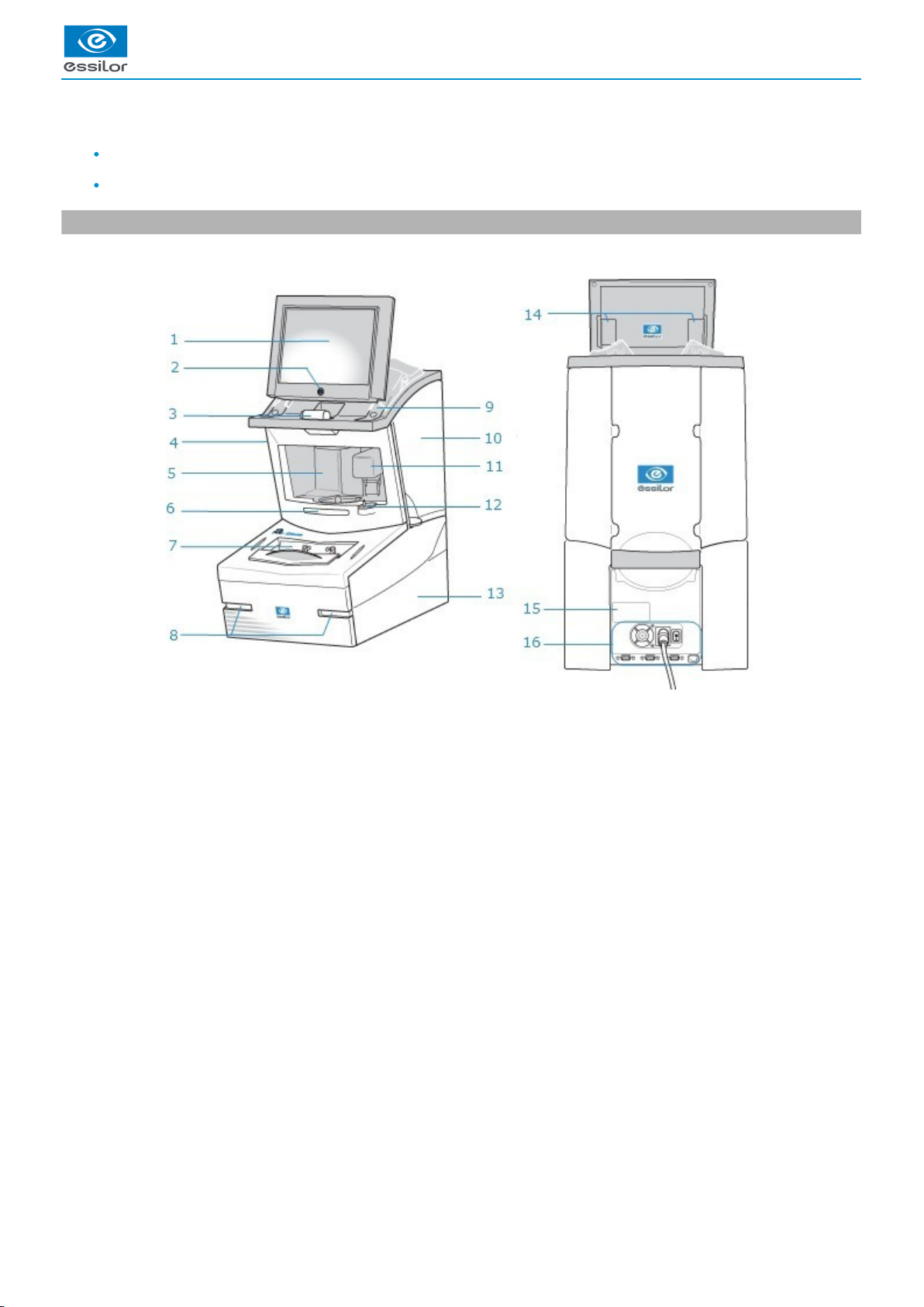
1. Descriptive diagrams
This section consists of descriptions and the list of accessories of the tracer-centerer-blocker:
Screen
ON/OFF button
Pattern holder
Operating accessory hatch
Centering chamber
Protective glass
Tracing table
Pad dispenser
Posiblock dispensers (on both sides of the screen)
Service accessory hatch
Blocking arm
Indexer
Access to roll of pads
Screen tilt buttons
Manufacturer plate
Connectors
USER MANUAL > FIRST STEPS WITH MR. BLUE 2.0
Mr Blue 2.0 > v4.0 -09.16 11
Page 12
1.
2.
3.
4.
5.
6.
7.
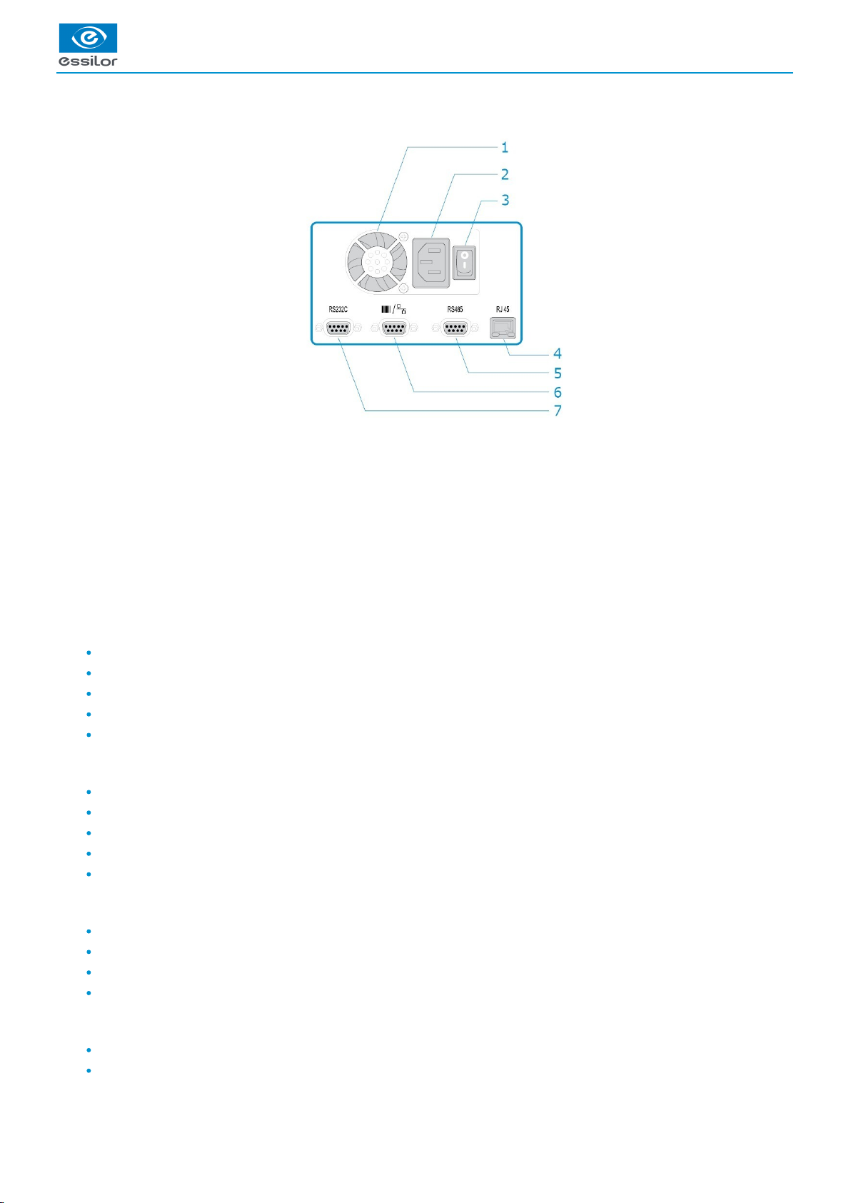
Connectors
Fan
Power socket
Main switch
Ethernet port
RS485 port
Barcode reader port
Serial port
Tracer accessories
Protective cover
Pattern holder
Bag of 22 mm posiblocks
Bag of 18x14 mm posiblocks
Transport wedges to be kept
Operating accessory hatch
High-base tripod
Recut lens tripod
Stylus
Small B-dimension wedges (quantity 2)
White felt tip marker
Service accessory hatch
Calibration posiblock
Pattern gauge (metal)
Frame gauge (black, numbered)
CD-ROM of calibration gauge data
Lower hatches
Roll of 22 mm pads
Roll of 18 x 14 mm pads
USER MANUAL > FIRST STEPS WITH MR. BLUE 2.0
12 Mr Blue 2.0 > v4.0 -09.16
Page 13
4
3
2
1
Options
Barcode reader
Roll of barcode labels
Connection accessories
220 V power cable
RJ45 cable for the tracer-edger connection
Essibox connection cable
2. Instructions for use
In this section, you will find all the information concerning the following:
turning the tracer-centerer-blocker and , on (p.13) off (p.14)
use of the touch screen and the keyboards (p.14),
the description of the work screen.tracer (p.15)
a. Turning on the tracer-centerer-blocker
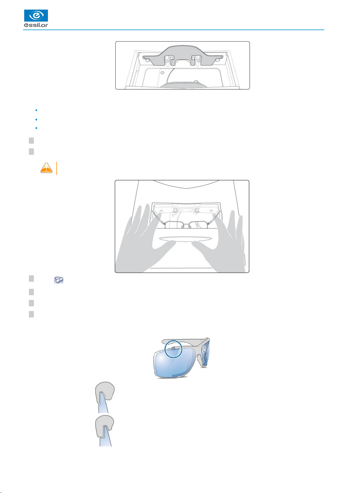
Before you switch on the tracer, make sure the tracing table is empty.
To switch on the tracer, press the main switch located at the rear of the machine.
The tracer may be switched on independently if you only want to do successive tracings.
Press the ON/OFF button located under the touch screen.
To ensure maximum precision and efficiency, the tracer needs 5 minutes to complete its initialisation after its
switch-on.
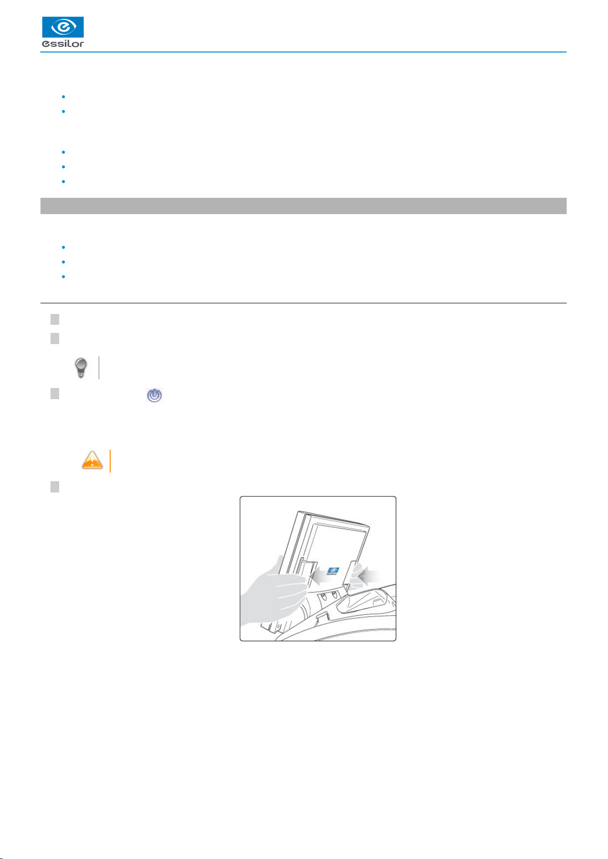
Press the two buttons located at the back of the screen to adjust the tilt angle if necessary.
The tracer is initialized.
A beep indicates that the initialisation was successful.
>
USER MANUAL > FIRST STEPS WITH MR. BLUE 2.0
Mr Blue 2.0 > v4.0 -09.16 13
Page 14
212
1
b. Turning off the tracer-centerer-blocker
Press briefly on the ON/OFF button under the touch screen or press , then .
Do not press the ON/OFF button for several seconds. This would result in a shut-down of the machine and a
warningmessage would be displayed at the next switch-on.
Select to confirm.
Extended period of non-use
For a prolonged period of non-use (a few days), it is preferable to turn off the tracer using the main switch.
c. Using the touch screen and keypads
Using the touch screen
Use the stylus supplied with the machine to use the touch screen.
After each use, you can rest the stylus on one of the stylus rests, represented by oval stickers.
You can also touch the screen with your finger.
If the screen is not sensitive enough to finger pressure, press lightly with a fingernail.
If the response area does not correspond to the position of the key, you need to calibrate the touch screen. For more
information, refer to the following section Maintenance and servicing > Checks and calibration > Calibrating the touch screen
.(p.125)
Never press hard on the screen as this could break it.
Never press on the screen with sharp objects such as pens, scissors, clamps, etc.
Screen breakage is not covered by the guarantee.
On the screen, press the icon-buttons to access the menus and job functions required.
Using the keypads
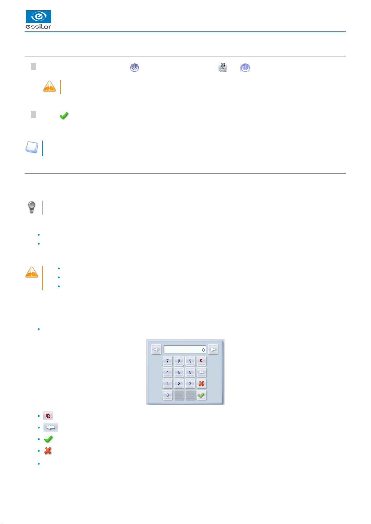
When you need to input or modify data, two types of keypads are automatically displayed, according to the information to be input.
The numeric keypad is displayed for the input of values.
Reset the fields
Back
Confirm
Cancel and go back to the work screen
The alphanumeric keypad is displayed to save or search for jobs.
A confirmation message is displayed on the screen.>
The tracer is turned off.>
USER MANUAL > FIRST STEPS WITH MR. BLUE 2.0
14 Mr Blue 2.0 > v4.0 -09.16
Page 15
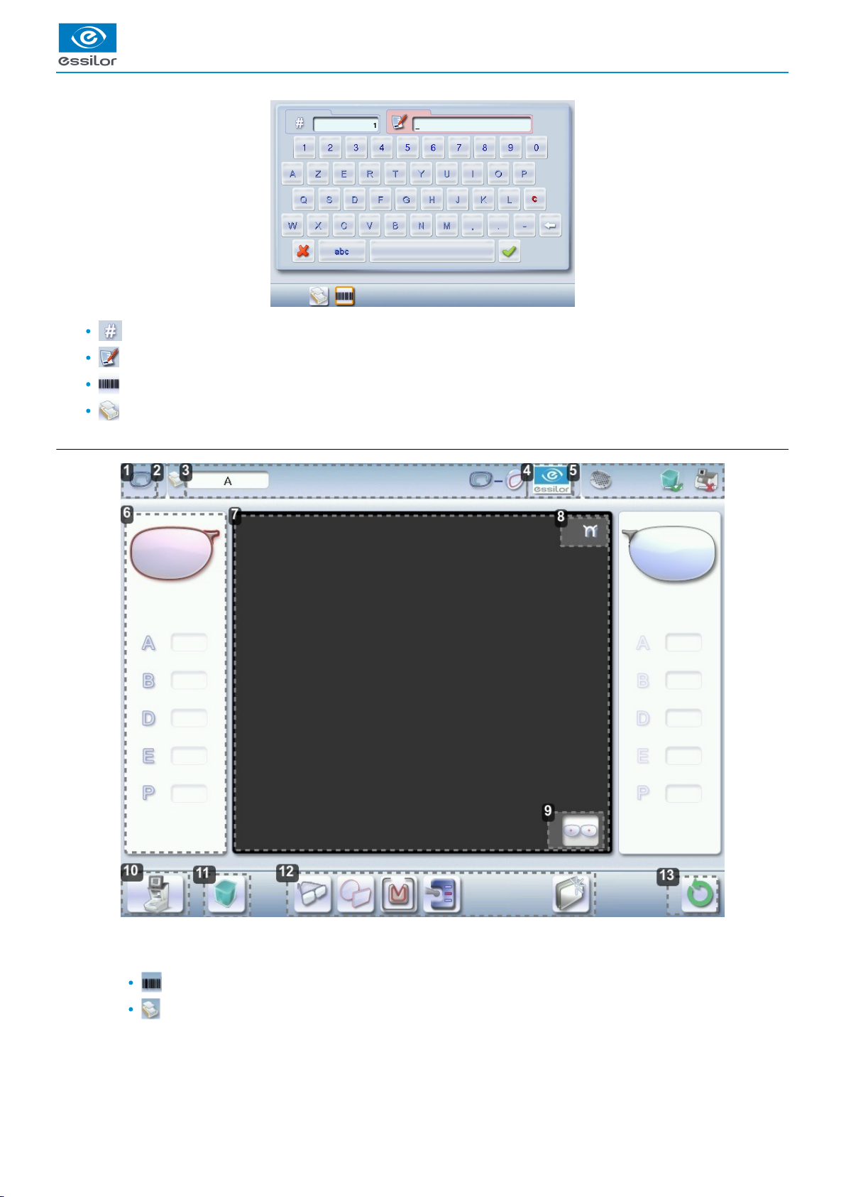
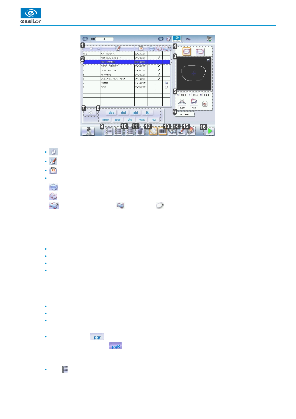
1.
2.
3.
4.
5.
Job ID
Job reference (alphanumeric characters)
list jobs
(p.148)
Collection list
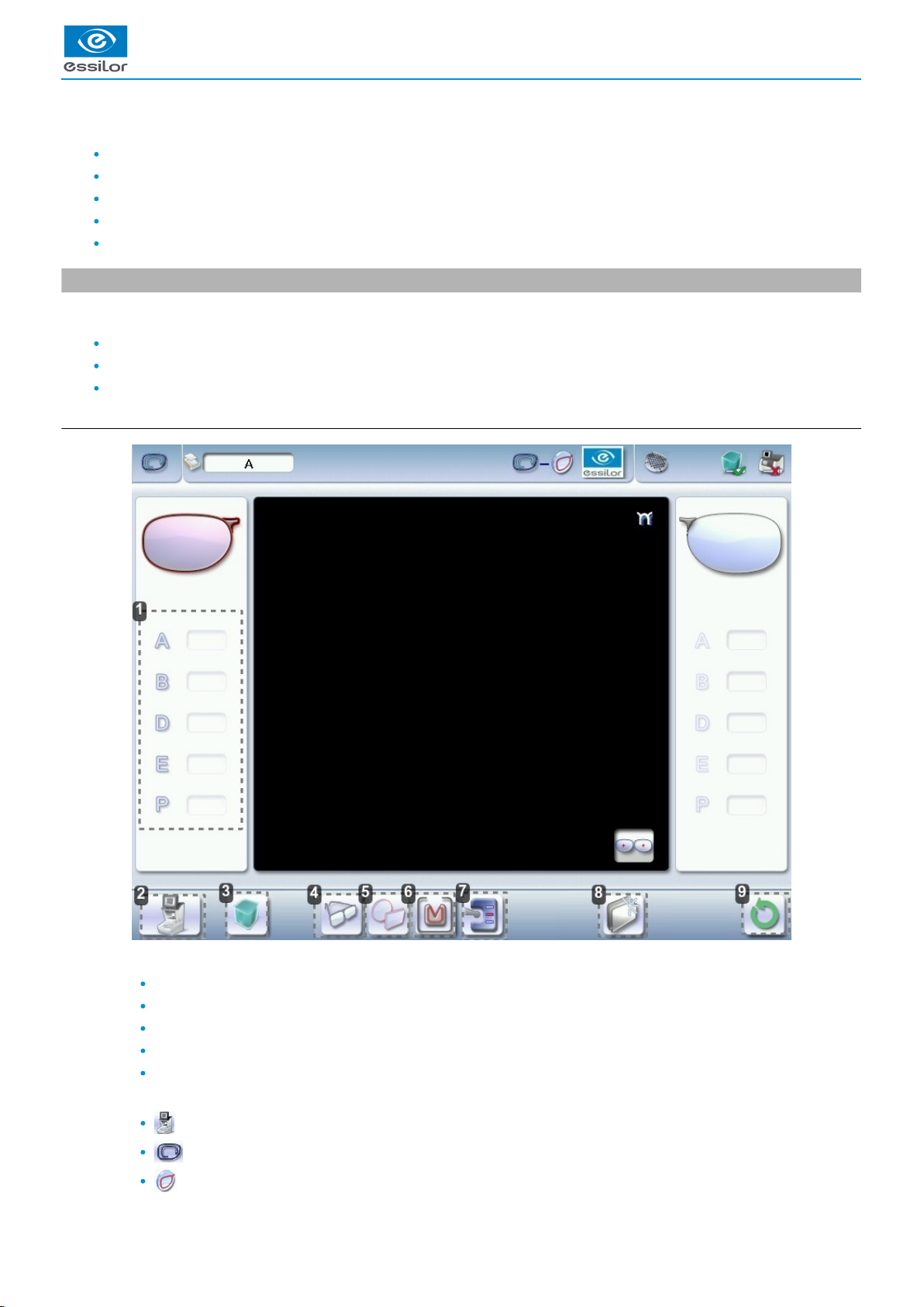
d. Tracing screen
Work screen indicator
Saved jobs list
Job list
Collection list
Information on the job and working mode
Settings
Devices connected
USER MANUAL > FIRST STEPS WITH MR. BLUE 2.0
Mr Blue 2.0 > v4.0 -09.16 15
Page 16

USER MANUAL > FIRST STEPS WITH MR. BLUE 2.0
6.
7.
8.
9.
10.
11.
12.
13.
Active eye and information on the shape
The right eye is selected by default.
The data on the left of the screen relates to the right eye, the data located on the right of the screen relates to the left eye.
Work area
Bridge
Located on the right for a right lens, and on the left for a left lens.
Binocular display
Function button: Tracer menu
Machine shutdown
Tracing screen
Centering screen
Shape management screen
Edging preparation (accessible according to the configuration chosen, for more information, consult the chapter
Set up the tracer-centerer-blocker>Customize the tracer>Work mode and display of measurements) (p.113)
Job call on Essibox
Actions available for the current screen
Tracing cycle initialization
Detailed functions
For more information, consult the section Perform a trace > Tracing environment > Captioned screen. (p.19)
16 Mr Blue 2.0 > v4.0 -09.16
Page 17

II. TRACING
Page 18

USER MANUAL > TRACING
18 Mr Blue 2.0 > v4.0 -09.16
Page 19
1.
2.
This chapter describes the procedures for the tracing of all types of frames, patterns, demo lenses and recut lenses:
Description of the tracing environment
Shape management and storage (p.22)
Tracing a rimmed frame (p.26) (including high-base frame)
Tracing a high-base frame (p.28)
Tracing a pattern, a demo lens or recut lens (p.30)
1. The tracing environment
This section describes the tracing screen and explains how to manage the jobs:
Description of the tracing screen (p.19)
Jobs and working modes (p.21)
Displaying the tracing completed in binocular mode (p.21)
a. Menu screen
Dimensions display
A: A-dimension
B: B-dimension
D: D-dimension
E: Larger radius from the Boxing center
P: Perimeter
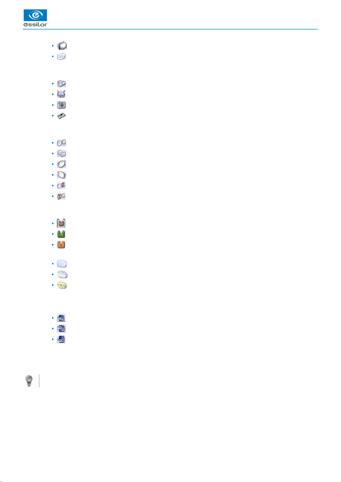
Function buttons
Machine shutdown
Tracing screen
Centering screen
USER MANUAL > TRACING
Mr Blue 2.0 > v4.0 -09.16 19
Page 20
2.
3.
4.
5.
6.
7.
8.
9.
Shape management screen
Edging preparation
Job call on Essibox
Tracing mode
Rimmed frame (including high-base frame)
High-base frame
Optical tracing (patterns, demo lenses or recut lenses)
Mechanical tracing (patterns, demo lenses or recut lenses)
This mode cannot be selected. It is activated automatically upon detection of the pattern holder in the tracing table.
Type of tracing
Symmetric binocular tracing
(p.149)
Asymmetric binocular tracing
(p.148)
Right-eye monocular tracing
Left-eye monocular tracing
Single monocular tracing of the right eye (blocking and possible edging of the right eye only)
Single monocular tracing of the left eye (blocking and possible edging of the left eye only)
Frame material or optical tracing type
For mechanical tracing of a frame:
Metal frame: high-precision tracing, with feeling of the groove
Plastic frame
Optyl , for particularly flexible framesframe
(p.149)
For optical tracing:
Demo lens//Recut lens, for frame typeNylor
©
Demo lens/Recut lens for drilled frame
Pattern
For mechanical tracing of demo lenses, recut lenses or patterns, the tracer automatically detects the pattern holder inserted
in the tracing table.
Groove detection
: insertion in the middle of the frame (default value),
: high insertion (up to 75% the height frame),
: low insertion (up to 25% of frame height),
New Job
For more information on , refer to the section .jobs
(p.148)
Tracing > Shape management and storage (p.22)
Tracing cycle initialization
Always browse from left to right: depending on your selection, certain menus will be available while others will not.
Automatic detection
You can configure the tracing for automatic detection. The frame material and type of optical tracing (pattern or demo lens) are
detected automatically.
To activate automatic detection on tracing, consult the section Configure the tracer-centerer-blocker > Customize the tracer > Action
bar. (p.115)
USER MANUAL > TRACING
20 Mr Blue 2.0 > v4.0 -09.16
Page 21

1.
2.
3.
4.
5.
b. Jobs and working modes
Jobs
A job consists in all the actions to be carried out to produce a pair of glasses. It can be managed in two ways:
Saved job: allocating an (ID) and a reference to the job makes it possible to save it and subsequently re-use it.ID
(p.148)
Automatic job archiving
Mandatory in the tracing - tracing work mode
Without saving: working in current mode (job identification by the letter A) enables you to process a job quickly without saving
it.
The job processing cycle must be finished before starting another.
If the cycle is stopped, a warning message is displayed and it is recommended to save the job.
Working modes
There are two working modes for managing your jobs:
The tracing-centering mode (by default)
The tracing-tracing mode
The selected work mode is shown in the information bar, to the left of the Essilor logo. You can change it in the tracer settings.
Working in the tracing - centering mode
After tracing, the tracer automatically displays the centering screen.
You can fully process a job before proceeding to the following:
Tracing or recovering a job from the database
Changing the shape and drilling position if necessary
Centering
Lens blocking
Lens edging
Working in the tracing - tracing mode
After tracing, the tracer displays the tracing screen again.
You can carry out several tracings in succession.
The tracings are saved with the job number you have allocated to them.
The shape modification, positioning of the drilling points, centering, blocking and edging of the lenses are handled
subsequently.
All jobs must be saved.
You can access the centering screen at any moment to centre the lens that corresponds to the active shape:
> Select then .
c. Displaying the binocular view
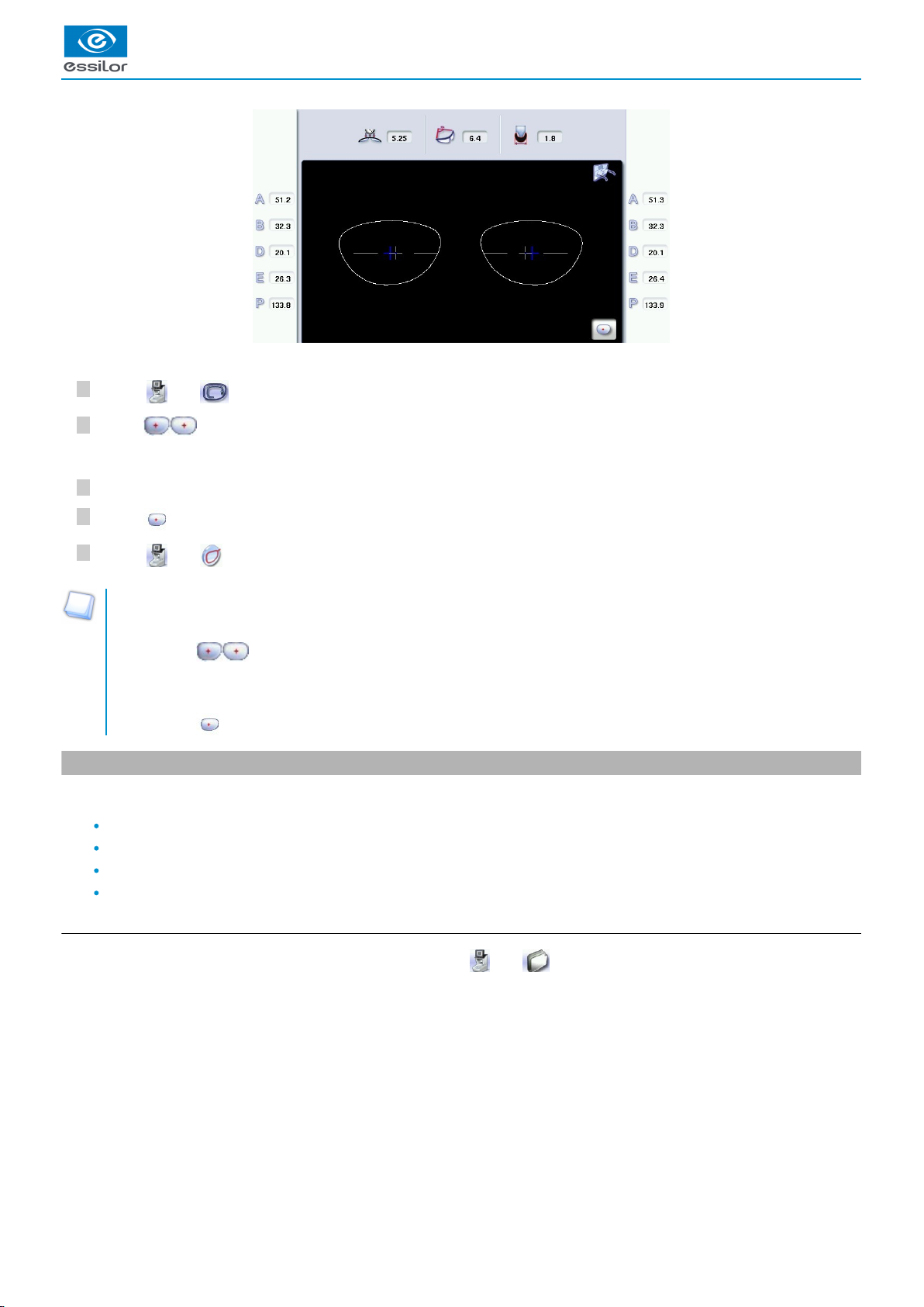
Once the tracing is finished, you can display a binocular representation of the job on a 1:1 scale, in order to check the frame shape
and centering.
Three values are displayed above the image:
the frame base
(p.148)
thecurve angle
(p.148)
the frame thickness
This symbol indicates the view from the wearer side.
USER MANUAL > TRACING
Mr Blue 2.0 > v4.0 -09.16 21
Page 22
5
4
3
2
1
1.
2.
3.
In tracing - centering mode, the centering screen is displayed at the end of the tracing:
Select then access the tracing screen.
Press to display the binocular view.
Position the frame in front of the screen, against the faceplate to check its shape and centering.
Press to return to the monocular screen.
Select then to go back to the centering screen.
Tracing - tracing mode
The tracing screen is displayed again once tracing is complete:
Press to display the binocular view.
> The binocular view is displayed.
Position the frame in front of the screen, against the faceplate to check its shape and centering.
Press to return to the monocular screen.
2. Shape management and storage
This section explains how to manage the available lists to store your shapes.
Description of the shape storage screen (p.22)
Job list and collection list (p.24)
Creating a job (p.24)
Working in current job mode (job A) (p.25)
a. Menu screen
From the tracing screen or the centering screen, press on the menu then to access the shape storage screen.
The binocular view is displayed.>
USER MANUAL > TRACING
22 Mr Blue 2.0 > v4.0 -09.16
Page 23
USER MANUAL > TRACING
1.
2.
3.
4.
5.
6.
7.
8.
9.
Sort the jobs
ID
(p.148)
Reference
Date
Types of jobs:
Drilled
Asymmetric tracings
Creative shapes/engravings: creative shape, shape with engraving
Selected job
Shape preview
Select the eye to be displayed in the preview
In monocular tracing mode, the eye just traced is displayed by default.
Information concerning the lens shape and frame
A, B and D dimensions
Frame base
Curve angle
Material of the frame / pattern / demo lens or recut lens
Job counter for the selected list
Back to the default display of the selected list
Display all jobs starting with the selected letter
To display the all jobs starting with the selected letter:
Press once if it is in the first position on the button,
Press twice in succession if it is in the second position,
Press three times in succession if it is in the third position.
Example:
Press 3 times on the buttonto display all jobs starting with the letter R.
> The R goes into upper case: .
> The jobs starting with the letter R are displayed.
Select several jobs
Press to select several non-consecutive jobs in the list.
Example: Press on the button then select jobs #1, #5, #7.
Mr Blue 2.0 > v4.0 -09.16 23
Page 24
2
1
9.
10.
11.
12.
13.
14.
15.
16.
> Only jobs #1, #5 and #7 are selected.
Press to select a group of consecutive jobs in the list, then select the first and last job in the group.
Example: Press on the button then select jobs #1 and #10.
> All jobs from #1 to #10 are selected.
Press to select all jobs in the list.
Select all jobs
Press to select all jobs for the search in progress.
Delete the selected job(s)
Press to delete the selected job(s). A confirmation message is displayed.
Job list or collection list
Select the list to be displayed:
Job list
Collection list
Search for a job by ID or by reference
Rename the selected job
Duplicate the selected job
Call the selected shape to the work area
b. Job list
Two lists are available for the storage of shapes:
The job list
The collection list
You can copy a job from one list to the other via the button .
The job list
The job list enables you to save jobs on a daily basis, without the possibility of re-using them at a later date. It can store up to 1,000
jobs.
The collection list
The collection list enables you to save specific jobs, for subsequent re-use:
Recurrent jobs
Standard shapes
Drilling models
It can store up to 1,000 jobs. The barcode reader (optional) cannot be used to call or save a job in the collection list; only the numeric
keypad can be used for that purpose.
c. Creating a job
There are several ways of creating a job:
Scan the barcode corresponding to the desired ID using the barcode reader (optional): the job is saved to the job list.
To create a job, use the alphanumeric keypad and follow the procedure below.
In the tracing screen, press in the action bar to create a new job.
For further information on data input and use of the keypad, refer to the following section: First steps > First use of
.the tracer-centerer-blocker > Using the touch screen (p.14)
Select the list in which you want to store the job:
The alphanumeric keypad is displayed.>
USER MANUAL > TRACING
24 Mr Blue 2.0 > v4.0 -09.16
Page 25
6
5
4
3
Press to select the job list.
Press to select the collection list.
For further information on the lists, refer to the section Tracing > Managing and storing shapes > Job list and
.collection list (p.24)
Press to enter the of the new job.ID
(p.148)
An ID is automatically allocated by the tracer (first free slot in the selected list). You can modify it: the ID can consist of
alphanumeric characters.
In the collection list, the ID solely consists of numeric characters.
Press to enter the reference of the new job.
Irrespective of the list selected, the reference may consist of alphanumeric characters. It can contain the information
of your choice:
Customer's name
Frame brand or reference
Manufacturer, etc.
Press to confirm.
Job list: Collection list:
The tracer is ready for tracing. For further information, refer to the section concerning your frame type.
The symbol is displayed is the upper right of the job ID if the right lens has been blocked but not the left.
If you don't want to save the job, you can work in current job mode. For more information, refer to the following section Tracing >
.Shape management and storage > Working in current job mode (job A) (p.25)
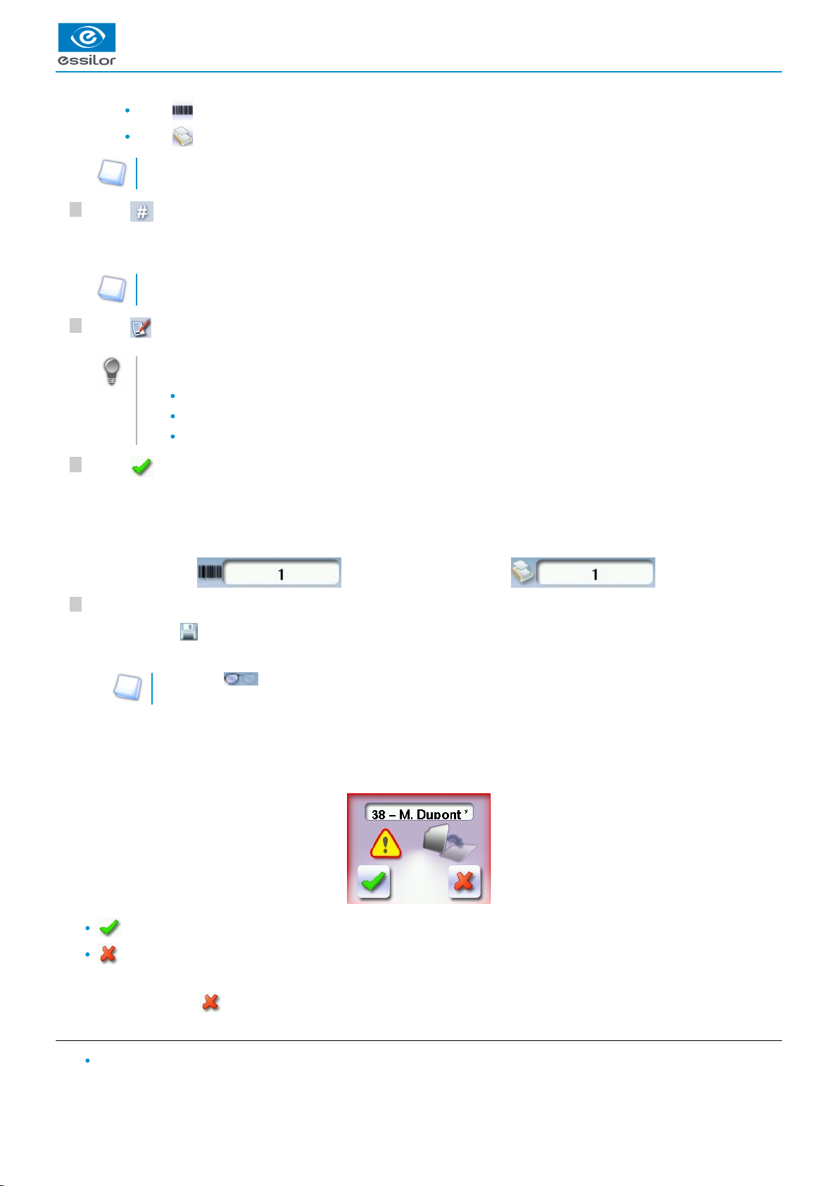
Successive tracings and saving.
If you start a new tracing while a job is still active on the tracing screen, a message is displayed:
Replacement of the active shape: the tracing you have just started replaces the former one under the current ID.
Creation of a new job: the alphanumeric keypad is displayed to enable you to create a new job for the tracing you have
just started (new ID). The two jobs are thus saved.
To cancel, press again on .
d. Working in current job mode (job A)
As soon as the tracer is initialised, you can work in current job mode: the letter A is displayed by default in the information
bar. The job is not saved.
The tracing screen is displayed. The ID allocated and the symbol of the list in which the job is stored appear in the
information bar.
>
The symbol is displayed at the bottom right of the job ID as soon as the job is being modified. It disappears once the
job has been saved.
>
USER MANUAL > TRACING
Mr Blue 2.0 > v4.0 -09.16 25
Page 26
6
5
4
3
2
1
If you want to save job A, refer to the .job creation procedure (p.24)
If you want to go back to job A after working on a saved job:
Scan barcode A using the barcode reader (optional), or
Use the numeric keypad and follow the procedure below.
In the tracing screen, press in the action bar to create a new job.
For further information on data input and use of the keypad, refer to the following section: First steps > First use of
.the tracer-centerer-blocker > Using the touch screen (p.14)
Select the list in which you want to store the job:
Press to select the job list.
Press to select the collection list.
For further information on the lists, refer to the section Tracing > Managing and storing shapes > Job list and
.collection list (p.24)
Press to enter the of the new job.ID
(p.148)
An ID is automatically allocated by the tracer (first free slot in the selected list). You can modify it: the ID can consist of
alphanumeric characters.
In the collection list, the ID solely consists of numeric characters.
Press to enter the reference of the new job.
Irrespective of the list selected, the reference may consist of alphanumeric characters. It can contain the information
of your choice:
Customer's name
Frame brand or reference
Manufacturer, etc.
Press to confirm.
Job list: Collection list:
The tracer is ready for tracing. For further information, refer to the section concerning your frame type.
The symbol is displayed is the upper right of the job ID if the right lens has been blocked but not the left.
3. Tracing a rimmed frame
Prerequisite:
For correct tracing of the shape, the frame to be traced must not be deformed and its hinges must be closed.
For a small frame, place the two wedges between the tracing table clamps:
The alphanumeric keypad is displayed.>
The tracing screen is displayed. The ID allocated and the symbol of the list in which the job is stored appear in the
information bar.
>
The symbol is displayed at the bottom right of the job ID as soon as the job is being modified. It disappears once the
job has been saved.
>
USER MANUAL > TRACING
26 Mr Blue 2.0 > v4.0 -09.16
Page 27
6
5
4
3
2
1
This section describes the procedure to follow for tracing rimmed frames including high-base frames:
Symmetric binocular
(p.149)
mechanical tracing of a rimmed frame
Asymmetric binocular
(p.148)
tracing of a rimmed frame
Monocular tracing of a rimmed frame
Place the frame in the tracing table, between the two clamps located opposite you.
Gently close the jaw to hold the frame.
Optyl
(p.149)
frames: take care not to flatten the frame by closing the jaws.
Press to select the type of rimmed frame.
Select the required type of tracing.
Select the frame material.
Select the type of groove insertion, medium, high or low.
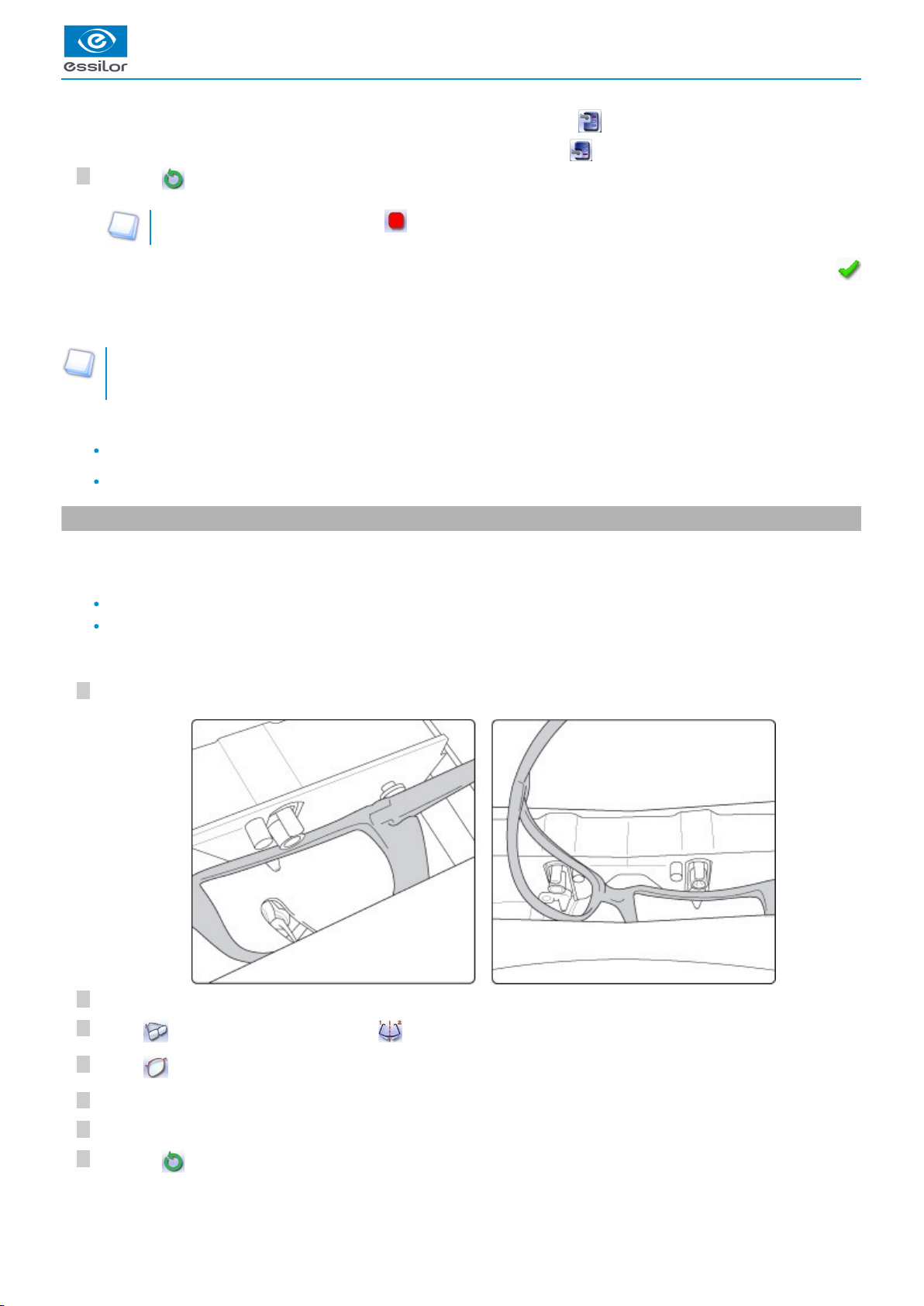
As part of the tracing of an asymmetrical groove frame (sport or safety frame): make sure to check the position of the groove
in the frame.
Groove located at the back of the frame
Groove located on the front of the frame
USER MANUAL > TRACING
Mr Blue 2.0 > v4.0 -09.16 27
Page 28
USER MANUAL > TRACING
7
6
5
4
3
2
1
7
In the case of a groove located at the back of the frame, select a high insertion .
In the case of a groove located in the front of the frame, select a low insertion .
Press on to start the tracing cycle.
To interrupt tracing at any time, press .
Tracing - tracing mode
In tracing - tracing mode, the result of the tracing is displayed in the work area of the tracing screen. For more information on
working modes, consult the section .Perform a trace > Tracing environment > Jobs and working modes (p.21)
Before Centering
If you want to modify the shape of the lenses, consult the chapter Modify the lens shape. (p.83)
If you want to add drilling points to your lenses, refer to the section Preparing a drilled job.
4. Tracing a high-base frame
This specific procedure enables you to trace a high-base frame, if the standard rimmed frame tracing fails.
Tracing of a high-base frame is done in two stages:
The frame is placed in the tracing table and mechanical tracing is done for each eye individually.
The curve angle is measured and the tracing is completed.
Put the frame in place and start the tracing
When you place the frame in the tracing table, position the eye as flat as possible: the black clamps which hold the eye to be
traced must be in the middle of the circle.
Gently close the jaw to hold the frame.
Press to select the high-base frame type.
Press to select the first eye to be traced.
Select the frame material.
Select the type of groove insertion, medium, high or low.
Press on to start the tracing cycle.
If you selected a monocular tracing, the numeric keypad is displayed. Enter the value of the D-dimension, then press
to confirm.
>
The tracing result is displayed in the centering screen, in monocular format on a 1:1.6 scale.>
28 Mr Blue 2.0 > v4.0 -09.16
Page 29
2
1
10
9
8
To interrupt tracing at any time, press .
Enter the value of the D-dimension, then press to confirm.
Position the frame to trace the second eye.
Press to start tracing the second eye.
Measuring the curve angle and completing the tracing.
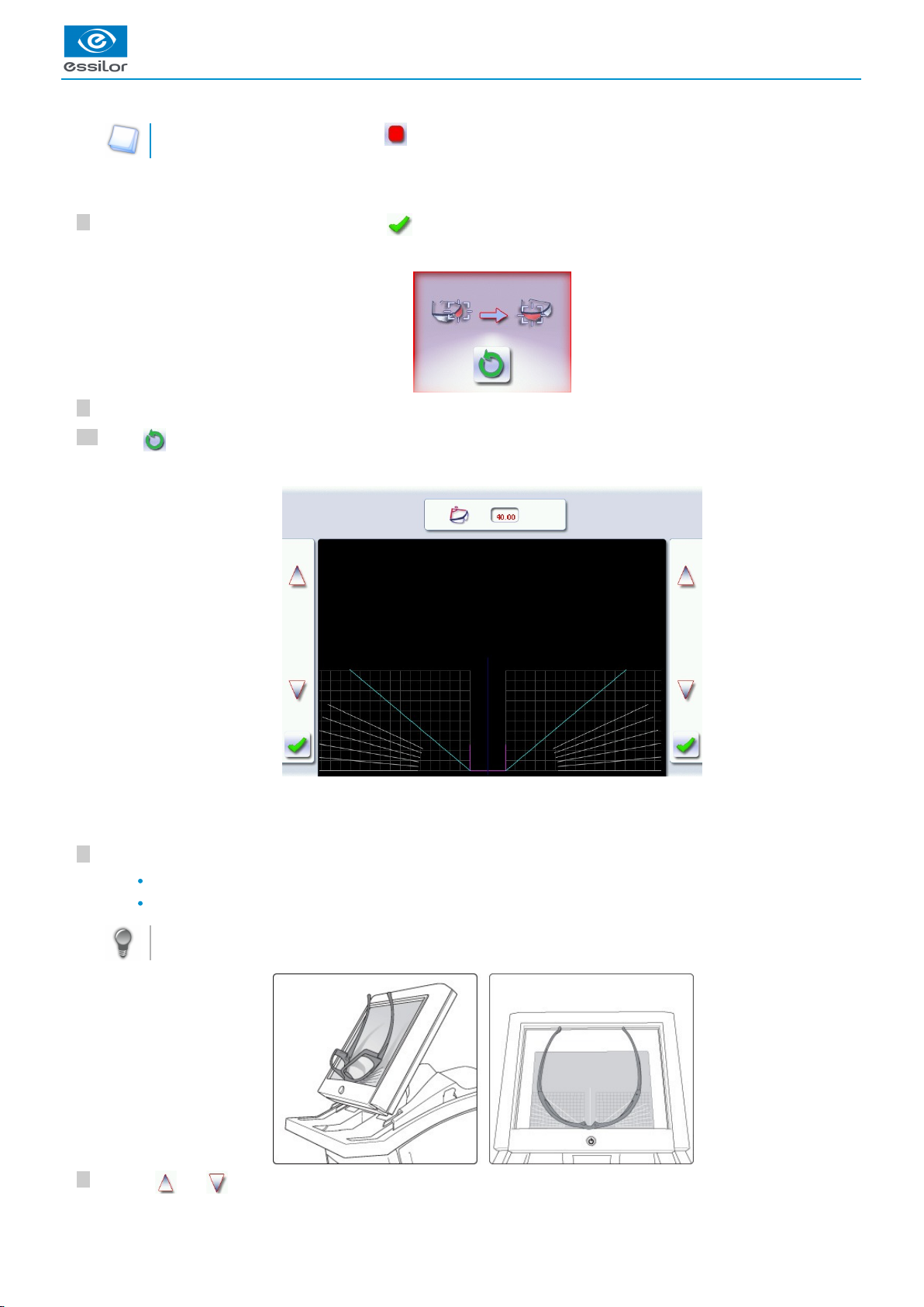
This screen enables you to measure the curve angle which cannot be captured in a monocular tracing.
Place the frame on the screen:
The vertical blue line must be in the center of the frame
The plane which is tangent to the two lenses must coincide with the pink line at the bottom.
If the frame doesn't stay straight, you can tilt the screen slightly by pressing the two side buttons at the back of the
screen.
Use the and buttons to align the light blue lines with the nasal and temporal ends of the rims.
The numeric keypad is displayed.>
Once the tracing of the first eye is finished, a message is displayed:>
The following screen is displayed:>
USER MANUAL > TRACING
Mr Blue 2.0 > v4.0 -09.16 29
Page 30
5
4
3
2
1
3
You can also press for a few seconds on the value and change it using the numeric keypad.
Press to confirm.
Tracing - tracing mode
In tracing - tracing mode, the result of the tracing is displayed in the work area of the tracing screen. For more information on
working modes, consult the section .Perform a trace > Tracing environment > Jobs and working modes (p.21)
Before Centering
If you want to modify the shape of the lenses, consult the chapter Modify the lens shape. (p.83)
If you want to add drilling points to your lenses, refer to the section Preparing a drilled job.
5. Tracing a pattern, a demo lens or recut lens
Two types of tracing are available for patterns, demo lenses and recut lenses: optical tracing and mechanical tracing. This section
also presents the operations to be carried out to enter the curve angle and frame base which cannot be captured in this type of
tracing.
Optical tracing (p.30)
Mechanical tracing (p.32)
Inputting the curve and the frame base after monocular tracing (p.34)
a. Optical tracing
Preparing optical tracing of demo or recut lens
This type of tracing makes it possible to retrieve the existing shape and drilling data of a lens.
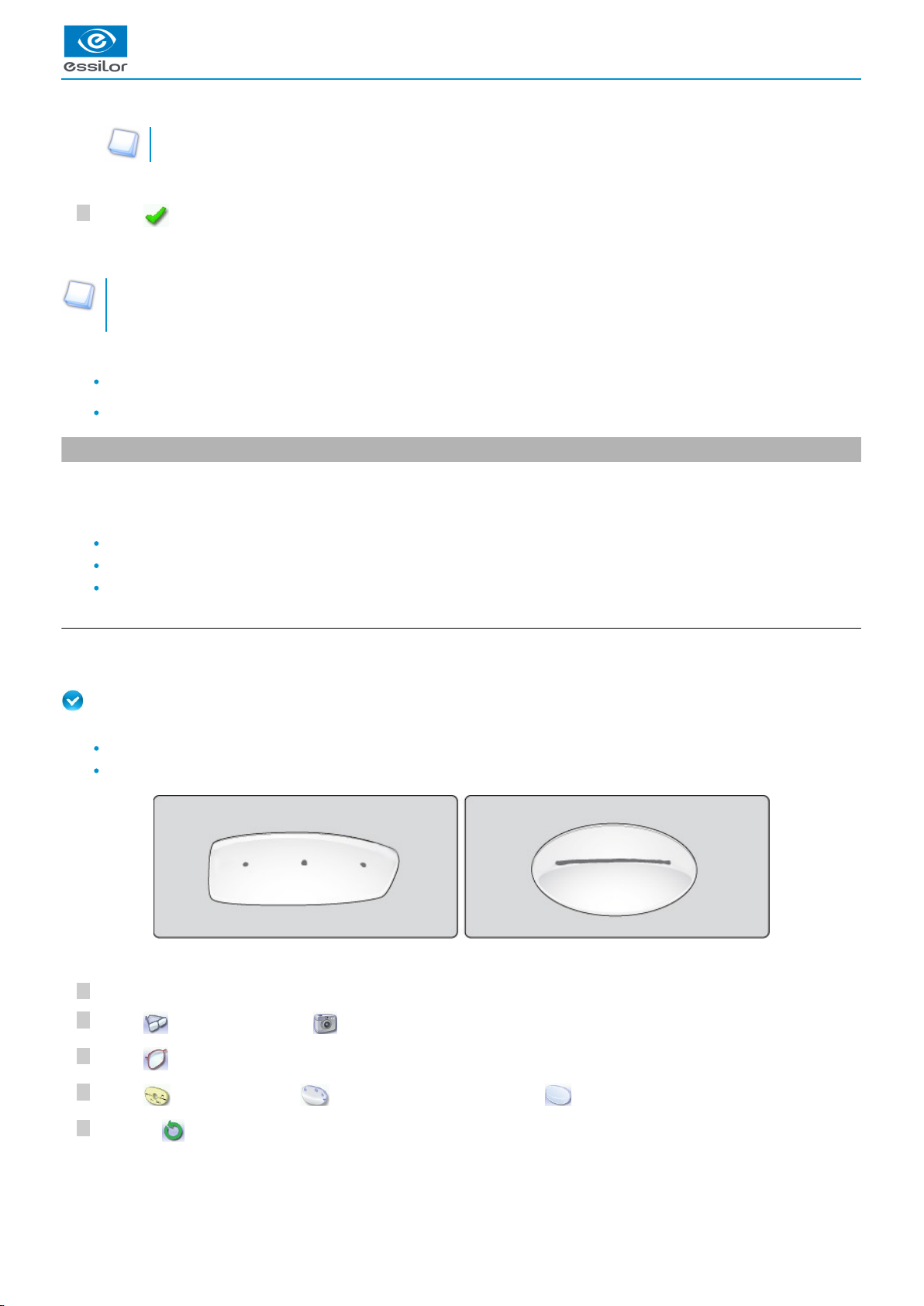
Prerequisite: for the tracer to correctly detect the horizontality of the lens, the lens must be clean and marked using the
permanent felt tip marker with:
either three focimeter dots,
or a horizontal line which must not touch the edges of the lens (a space of at least 5 mm is required)
Tracing
Place the pattern or the lens in the middle of the centering chamber.
Press to select optical tracing .
Press to select the eye to be traced.
Press to select the pattern, to select the demo or re-cut lens or to select the lens for a Nylor frame .
©
Press on to start the tracing cycle.
The value of the curve angle is modified.>
The tracing result is displayed in the centering screen, in monocular format on a 1:1.6 scale.>
USER MANUAL > TRACING
30 Mr Blue 2.0 > v4.0 -09.16
Page 31

8
7
6
To interrupt tracing at any time, press .
Enter the value of the D-dimension, then press to confirm.
Configure the drilling points if required.
For more information, refer to the section .Preparing a drilled job (p.91)
Press to go to the centering screen.
Tracing - tracing mode
In tracing - tracing mode, the result of the tracing is displayed in the work area of the tracing screen. For more information on
working modes, consult the section .Perform a trace > Tracing environment > Jobs and working modes (p.21)
Before Centering
Once tracing has been carried out, you can:
Input the curve angle and the frame base, for optimal centering precision
Modifying the lens shape For more information, consult the chapter .Modifying the lens shape (p.83)
Add drilling points on the shape. For more information, consult the chapter .Preparing a drilled job (p.91)
If the tracer does not detect either the focimeter dots or the line on the lens an error message will be displayed: check and /
or mark the lens again with the focimer dots or the line. If the tracing fails after the check, do a mechanical tracing using the
pattern holder.
>
The numeric keypad is displayed.>
The drilling screen is displayed.>
USER MANUAL > TRACING
Mr Blue 2.0 > v4.0 -09.16 31
Page 32

2
1
3
2
1
2
1
3
2
1
1.
2.
3.
4.
5.
6.
7.
8.
b. Mechanical tracing
Detailed view of the pattern holder
Front tab
Knurled knob to screw
“Right nose” inscription
Back tab
Posiblock clamp
18x14 mm posiblock
Pattern-holder tip
Holding screw
Attaching a recut lens or demo lens to the pattern holder
Block the lens in the boxing center, making sure it is properly centered.
Insert the blocked lens in the posiblock clamp, holding it in position with your index finger.
Press on the knurled button, screwing, until the blocked lens is immobilized.
The feeling pressure on the lens being weak, it is pointless to excessively screw down the knurled button.
Attaching a pattern to the pattern holder
Unscrew the screw holding the pattern-holder tip.
Fix the pattern on the pattern-holder tip:
The lens is clamped.>
USER MANUAL > TRACING
32 Mr Blue 2.0 > v4.0 -09.16
Page 33

1
5
4
3
2
1
4
3
1
5
4
3
2
1
4
3
nose to the right for a right lens, and to the left for a left lens
pattern-holder tip positioner towards the bottom of the pattern.
Align the marking (right nose) or (left nose) of the pattern holder with that of the pattern:
nose to the right for a right lens, and to the left for a left lens
pattern-holder posiblock positioner towards the bottom of the pattern
Press on the knurled knob, screwing it, until the pattern is immobilized (as for fixing a lens).
The screwing of the knurled knob inside the posiblock of the nozzle has no functional impact on the latter.
Place the pattern holder in the tracing table
Insert the front tab of the support between the white cylindrical studs of the tracing table.
Block the back tab of the support.
Adjust the jaws of the tracing table so as to block the pattern holder.
Start the cycle.
Release the pressure on the white circles so the rear tab goes into the slit located opposite the cylindrical white pins (next to
you - see illustration below).
Check that the pattern holder does not move in the table.
Tracing
Press to start the mechanical tracing.
To interrupt the tracing at any time, press .
The pattern is clamped.>
The tracer automatically detects the pattern holder.>
USER MANUAL > TRACING
Mr Blue 2.0 > v4.0 -09.16 33
Page 34

3
2
1
323
2
Select the eye to be traced.
Enter the D-dimension, then press to confirm.
Tracing - tracing mode
In tracing - tracing mode, the result of the tracing is displayed in the work area of the tracing screen. For more information on
working modes, consult the section .Perform a trace > Tracing environment > Jobs and working modes (p.21)
Before Centering
Once tracing has been carried out, you can:
Input the curve angle and the frame base, for optimal centering precision
Modifying the lens shape For more information, consult the chapter .Modifying the lens shape (p.83)
Add drilling points on the shape. For more information, consult the chapter .Preparing a drilled job (p.91)
c. Inputting the curve and the frame base after monocular tracing
In a monocular tracing, the curve angle and frame base cannot be measured. For optimal centering precision, we recommend that
you enter those values after the optical or mechanical tracing of a pattern, recut lens or demo lens.
Prerequisite: before entering the curve angle and frame base, one of the following operations must be performed:
Optical tracing of a pattern, a demo lens or a recut lens (p.30)
Mechanical tracing of a pattern, demo lens or recut lens (p.32)
Input the curve angle and the frame base.
Press the button.
Select the curve angle value to modify it.
Place the frame on the screen:
The vertical blue line must be in the center of the frame
The plane which is tangent to the two lenses must coincide with the pink line at the bottom.
The buttons , , and are displayed.
>
The numeric keypad is displayed.>
The tracing result is displayed in the centering screen, in monocular format on a 1:1.6 scale.>
The following screen is displayed:>
The value is displayed in red.>
USER MANUAL > TRACING
34 Mr Blue 2.0 > v4.0 -09.16
Page 35

7
6
5
4
If the frame doesn't stay straight, you can tilt the screen slightly by pressing the two side buttons at the back of the
screen.
Use the and buttons to align the light blue lines with the nasal and temporal ends of the rims.
You can also press for a few seconds on the value and change it using the numeric keypad.
Select the frame base value to modify it.
Use the and buttons to modify the frame base value.
You can also press for a few seconds on the value and change it using the numeric keypad.
Press to confirm.
The value of the curve angle is modified.>
The value is displayed in red.>
USER MANUAL > TRACING
Mr Blue 2.0 > v4.0 -09.16 35
Page 36

USER MANUAL > TRACING
36 Mr Blue 2.0 > v4.0 -09.16
Page 37

III. CENTERING A LENS
Page 38

USER MANUAL > CENTERING A LENS
38 Mr Blue 2.0 > v4.0 -09.16
Page 39

1.
This chapter describes the lens centering procedures according to the type of lens.
Description of the centering environment (p.39)
Centering a single vision lens (p.42)
Centering a progressive lens (p.52)
Centering a bifocal lens (p.58)
Centering an executive lens (p.64)
Centering a mid-distance lens (p.69)
Centering a lens for a high-base frame (p.76)
Saving a new marking (p.77)
This chapter also describes the procedure.lens blocking (p.80)
The tracer can be used to calculate the lens power. Nevertheless, is not categorized as a focimeter. Standard ISO8598-1
implies measurement on a cone 5 mm in diameter.
Tracer-centerer-blocker performance
To get the most out of the tracer-centerer-blocker and take advantage of all its features, we recommend that you follow the
advice below:
Eliminate any source of light (natural or artificial) pointing directly towards the centering chamber, to avoid interfering
with lens measurement and centering.
Check that the lenses are clean before proceeding with automatic centering.
Hartmann plate protective glass:
Clean the window located in the middle of the centering chamber regularly.
Replace it as soon as it shows traces of scratches in the center.
(For more information, consult the section Maintenance > Maintaining and cleaning the
.)tracer-centerer-blocker > Cleaning the protective glass of the Hartmann plate (p.132)
1. Centering environment
This section describes the centering screen and the various centering modes available:
Description of the centering screen (p.39)
Centering modes (p.41)
a. Menu screen
Centering screen indicator
USER MANUAL > CENTERING A LENS
Mr Blue 2.0 > v4.0 -09.16 39
Page 40

USER MANUAL > CENTERING A LENS
2.
3.
4.
5.
6.
7.
8.
9.
10.
11.
12.
13.
Work area
Nasal side indicator
Lens shape
Centering target according to lens type (white cross)
Boxing center of the shape (blue cross)
Active eye and type of display of PD and pupillary height
Four modes available:
Boxing mode
Datum mode
ΔY mode
ΔX + ΔY mode
For more information on the type of display, consult the section Configure the tracer-centerer-blocker > Customize the tracer
.> Decentration mode (p.115)
Half PD
Pupillary height
Lens information
Sphere power in diopters
Cylinder power in diopters
Press on the area for a few seconds to switch from a positive cylinder power to a negative one.
Cylinder angle
The display of this data is customizable. For more information, refer to the section Configuring the digital system >
Customizing the tracer > Working mode and display of measurements. (p.113)
Lens type selection
Single vision lens
(p.149)
Progressive lens
(p.149)
Bifocal lens
(p.149)
Executive lens
(p.148)
Mid-distance lens
(p.149)
Centering mode selection
Automatic centering
Centering using three focimeter dots
Centering using re-marked micro-engravings
Centering using manufacturer markings
Manual centering
Cylinder angle
Press on the area to display the numeric keypad and enter the desired value.
Value modification
Reduce or increase the previously selected value.
Change the value between the PD and pupillary height and vice-versa
Shape modification
Provides access to the shape modification screen. For more information, consult the following chapter Modifying the lens
.shape (p.83)
Drilling preparation
Provides access to the drilling screen. For more information, consult the chapter .Preparing a drilled job (p.91)
40 Mr Blue 2.0 > v4.0 -09.16
Page 41

14. Start the centering cycle
To start the centering.
Always browse from left to right: depending on your selection, certain menus will be available while others will not.
b. Centering modes
The centering modes available depend on the selected lens type.
Always refer to the specific procedure for your type of lens.
Using the tripods
Two accessories are available to ensure better stability of high-curve lenses and small lenses. In the centering chamber, you
can thus place:
the high-base lens tripod
(p.149)
the recut lens tripod
(p.149)
USER MANUAL > CENTERING A LENS
Mr Blue 2.0 > v4.0 -09.16 41
Page 42

1.
2.
Hartmann plate calibration
The automatic calibration of the Hartmann plate is done periodically to ensure optimal precision.
During the first half-hour following the booting of the machine: every 30 seconds.
After the first half-hour: every minute.
After three hours of operation: every 5 minutes.
If a lens is present in the centering chamber during the calibration, a warning is displayed:
Remove the lens and press .
> The calibration starts automatically.
> Once the calibration is finished, a warning message is displayed:
Put the lens back in place and press .
> The centering resumes.
To avoid all interference with the Hartmann plate calibration, place the lens in the centering chamber just before you start the
centering.
2. Centering a single vision lens
Prerequisite: Before centering the lens, you must first trace a shape in the centering screen.
If necessary, we recommend the following prior operations:
Modifying or retouching the traced shape (p.83)
Preparing drilling points (p.91) to be created
Place the stickers recommended by the manufacturer on hydrophobic lenses.
This section describes the procedures for the centering of a single vision lens:
Centering in automatic mode (p.43)
Centering using three focimeter dots (p.45)
Centering using re-marked micro-engravings (p.48)
USER MANUAL > CENTERING A LENS
42 Mr Blue 2.0 > v4.0 -09.16
Page 43

7
6
5
4
3
2
1
Centering in manual mode (p.51)
It also describes the which makes it possible to limit the induced prism, and to ensure a job of quality.job function “lens fit” (p.50)
Do not center the (thickness < 0.8 mm) in automatic mode or in three focimeter dots mode, youlenses precalibrated
(p.149)
are likely to break them with blocking.
a. Centering a single vision lens in automatic mode
Do not use this mode for a lens marked with a focimeter: the markings can alter the precision of the centering.
Press to select the type of single vision lens.
Press to select the automatic centering mode.
Press to enter the cylinder angle (if the lens has one).
This information makes it possible to straighten the lens perfectly at the angle required by the prescription, then
ensure that the posiblock is set on the same axis.
When you start the blocking of a cylindrical lens without having indicated the angle value, a warning is displayed at
the start of the blocking operation:
Press if you don't want to change the default value (default value = 0°).
Press if you want to modify this value. The numeric keypad is displayed.
Enter the desired value, then press to confirm.
Enter the half-PD and pupillary height.
Modify the distance between the PRP (point of reference prismatic) and centering cross, if necessary:
This value is configured by default at 4 mm for Essilor mid-distance lenses (EyeZen). This value may vary, depending
on lens manufacturers.
Position the lens in the middle of the centering chamber.
The centering target is displayed.>
The angle value is displayed in the centering screen.>
The target moves.>
USER MANUAL > CENTERING A LENS
Mr Blue 2.0 > v4.0 -09.16 43
Page 44

8
Press to start lens tracing.
Once the lens is held by the clamps, it must not be handled.
To stop centering at any time, press .
Display of the optical center of the lens (white cross) and boxing center of the shape (blue cross)
Display of the power of the sphere (within the limit of + or -6°)
Display of the cylinder power
Lens fit check
A visual warning enables you to check the lens fit: any part of the lens outside the shape is displayed in red.
To get the shape to fit into the lens, you can:
Use the lens fit function .
For more information, refer to the section .Centering a lens > Centering a single vision lens > Lens fit function (p.50)
Modify the PD and pupillary height.
If modifying the PD and pupillary height results in too great an induced prism, we advise you to order a new lens in
the proper diameter.
The clamps close on the lens to hold it in position until its blocking.>
The lens analysis starts: the tracer searches for the optical characteristics of the lens.>
The centered lens is displayed in the work area:>
The lens is centered and ready to be blocked.>
USER MANUAL > CENTERING A LENS
44 Mr Blue 2.0 > v4.0 -09.16
Page 45

3
2
1
To carry out lens blocking, refer to the section .Centering a lens > Blocking a lens (p.80)
b. Centering a single vision lens using three focimeter dots
This centering mode is suited to the following types of lenses:
Lenses with cylinder values are above the automatic centering limits
Polarising lenses
Lenses with degraded colors
Prismatic lenses
Prerequisite: The lens must be marked with the focimeter.
The three focimeter dots must be:
Lined up
At the same distance from the central dot
0.5 to 1.5 mm in diameter
Centering the lens
Add a mark to enable the tracer to distinguish the top of the lens.
The "top of lens" mark must:
be located in the upper part of the lens
be positioned 1 to 2 cm above the focimeter dots
be a thick shape contained in a 1 cm square.
The shape is free-form.
Do not make any mark in the lower part of the lens.
Press to select the type of single vision lens.
Press to select the automatic centering mode using three focimeter dots.
The centering target is displayed:>
USER MANUAL > CENTERING A LENS
Mr Blue 2.0 > v4.0 -09.16 45
Page 46

6
5
4
Enter the half-PD and pupillary height.
Position the lens in the middle of the centering chamber.
Press to start lens tracing.
Once the lens is held by the clamps, it must no longer be handled.
To stop centering at any time, press .
Yellow indicators are displayed on the focimeter dots: the centering is perfect.
Display of the optical center of the lens (white cross) and boxing center of the shape (blue cross)
Display of the sphere power
Display of the cylinder power
The cylinder angle is displayed:
The lens base is displayed:
The target moves.>
The clamps close on the lens to hold it in position until its blocking.>
The lens analysis starts: the tracer searches for the optical characteristics of the lens.>
The centered lens is displayed, along with its characteristics, in the work area:>
The lens is centered and ready to be blocked.>
USER MANUAL > CENTERING A LENS
46 Mr Blue 2.0 > v4.0 -09.16
Page 47

Lens fit check
A visual warning enables you to check the lens fit: any part of the lens outside the shape is displayed in red.
To get the shape to fit into the lens, you can:
Use the lens fit function .
For more information, refer to the section .Centering a lens > Centering a single vision lens > Lens fit function (p.50)
Modify the PD and pupillary height.
If modifying the PD and pupillary height results in too great an induced prism, we advise you to order a new lens in
the proper diameter.
To carry out lens blocking, refer to the section .Centering a lens > Blocking a lens (p.80)
USER MANUAL > CENTERING A LENS
Mr Blue 2.0 > v4.0 -09.16 47
Page 48

6
5
4
3
2
1
6
5
4
3
2
1
6
5
4
3
2
1
c. Centering a single vision lens using re-marked micro-engravings
Mark the micro-engravings present on the lens.
Mark the near vision micro-engravings with a felt tip marker.
Remark each micro-engraving with a felt tip marker. The diameter of the dots must be between 0.5 and 1.5 mm.
If the manufacturer marking forms two circles around the micro-engravings, erase them before marking the lens with a
felt tip marker.
We advise you to use:
the white felt tip marker supplied with the tracer to mark the lens
an alcohol-based solution such as Essiclean to remove existing markings.
TM
Press to select the type of single vision lens.
Press to select the centering mode starting at the micro-engravings.
Enter the half-PD and pupillary height.
Enter the half-PD and pupillary height.
If necessary, modify the distance between the PRP (prismatic reference point) and the centering cross .
This value is configured by default at 0 mm for the Essilor single vision lenses. This value may vary, depending on
lens manufacturers.
Position the lens in the middle of the centering chamber.
The centering target is displayed:>
The target moves.>
The target moves.>
USER MANUAL > CENTERING A LENS
48 Mr Blue 2.0 > v4.0 -09.16
Page 49

777
Press to start lens tracing.
Once the lens is held by the clamps, it must not be handled.
To stop centering at any time, press .
The clamps close on the lens to hold it in position until its blocking.>
The lens analysis starts: the tracer searches for the optical characteristics of the lens.>
The centered lens is displayed in the work area.>
The lens is centered and ready to be blocked.>
USER MANUAL > CENTERING A LENS
Mr Blue 2.0 > v4.0 -09.16 49
Page 50

USER MANUAL > CENTERING A LENS
Lens fit check
A visual warning enables you to check the lens fit: any part of the lens outside the shape is displayed in red.
You can modify the PD and pupillary height to get the shape to fit into the lens, but if the induced prism is too great, we
advice you to order a new lens in the proper diameter.
To carry out lens blocking, refer to the section .Centering a lens > Blocking a lens (p.80)
d. "Lens fit" function
This function is available only for single vision lenses centered in automatic mode or using three focimeter dots.
(Refer to the sections and Centering a single vision lens > Automatic mode (p.43) Centering a single vision lens > Three focimeter
).dots mode (p.45)
It enables you to limit the induced prism and ensure a quality job.
Once the lens has been centered, if part of the shape representing the frame rim is outside the lens diameter, it is indicated in red:
Modifying the pupillary half distances and heights may result in too great an induced prism and create a risk of discomfort for
the wearer.
The maximum value is 0.25 prism diopter.
Using the "lens fit" function
Press .
> The shape appears in the lens.
> The induced prism power is displayed:
In green if it allows adequate job results In red if does not allow adequate job results
50 Mr Blue 2.0 > v4.0 -09.16
Page 51

4
3
2
1
1.
2.
e. Centering a single vision lens in manual mode
Manual centering enables you to center the lenses which:
cannot be centered in automatic mode
cannot be centered automatically using the three focimeter dots
Prerequisite: The lens must be marked with the focimeter.
The three focimeter dots must be:
Lined up
At the same distance from the central dot
0.5 to 1.5 mm in diameter
Description of the centering target
Optical center of the lens (white cross) and boxing center of the shape (blue cross)
Centering marks
Centering the lens
Press to select the type of single vision lens.
Press to select the manual centering mode.
Enter the half-PD and pupillary height.
Position the lens on the clamps and center it in keeping with the target.
You can control the opening and closing of the clamps for better control of the stability of the lens:
Press to open the clamps.
Press to close the clamps.
As soon as you place the marked lens on the clamps, the tracer automatically detects the focimeter dots.
You can choose to center the lens on the protective glass: open the clamps completely.
Do not manually center the (thickness < 0.8 mm) directly on the window. Theprecalibrated lenses
(p.149)
lenses would be liable to break during blocking.
Take care not to damage the protective glass with glass lenses.
Press to zoom.
The clamps close:the image of the centering chamber is displayed in real time.>
The white target moves.>
USER MANUAL > CENTERING A LENS
Mr Blue 2.0 > v4.0 -09.16 51
Page 52

To carry out lens blocking, refer to the section .Centering a lens > Blocking a lens (p.80)
3. Centering a progressive lens
Prerequisite: Before centering the lens, you must first trace a shape in the centering screen.
If necessary, we recommend the following prior operations:
Modifying or retouching the traced shape (p.83)
Preparing drilling points (p.91) to be created
Place the stickers recommended by the manufacturer on hydrophobic lenses.
This section describes the procedures for the centering of a progressive lens:
Centering using re-marked micro-engravings (p.53)
Centering using manufacturer markings mode (p.55)
Centering in manual mode (p.57)
Do not center the (thickness < 0.8 mm) in manufacturer markings mode or in re-markedprecalibrated lenses
(p.149)
micro-engravings mode, you are likely to break them with blocking.
Yellow indicators are displayed on the focimeter dots: the centering is perfect.
>
The lens is centered and ready to be blocked.>
USER MANUAL > CENTERING A LENS
52 Mr Blue 2.0 > v4.0 -09.16
Page 53

3
2
1
3
2
1
3
2
1
a. Centering a progressive lens using re-marked micro-engravings
Mark the micro-engravings present on the lens. To do this, you have two options:
First option:
Mark the micro-engravings while keeping the original marks:
Remark each micro-engraving with a felt tip marker. The diameter of the dots must be between 0.5 and 1.5 mm.
If the manufacturer marking forms two circles around the micro-engravings, erase them before marking the lens with a
felt tip marker.
We advise you to use:
the white felt tip marker supplied with the tracer to mark the lens
an alcohol-based solution such as Essiclean to remove existing markings.
TM
Second option:
Mark the micro-engravings after having removed all original marks:
Remark each micro-engraving with a felt tip marker. The diameter of the dots must be between 0.5 and 1 mm.
Around the two micro-engravings, draw a circle with a diameter of 5 to 10 mm.
Keep or redraw the near vision area.
Make sure you close the circles and that they are not too small (minimum diameter 5 mm).
We advise you to use:
the white felt tip marker supplied with the tracer to mark the lens
an alcohol-based solution such as Essiclean to remove existing markings.
TM
Press to select the type of progressive lens.
Press to select automatic centering using re-marked micro-engravings.
USER MANUAL > CENTERING A LENS
Mr Blue 2.0 > v4.0 -09.16 53
Page 54

6
5
4
6
5
4
6
5
4
Enter the half-PD and pupillary height.
If necessary, modify the distance between the PRP (prismatic reference point) and the centering cross .
This value is configured to 4 mm by default for Essilor progressive lenses. This value may vary, depending on lens
manufacturers.
Position the lens in the middle of the centering chamber.
Press to start lens tracing.
Once the lens is held by the clamps, it must not be handled.
To stop centering at any time, press .
The centering target is displayed:
>
The target moves.>
The clamps close on the lens to hold it in position until its blocking.>
The lens analysis starts: the tracer searches for the optical characteristics of the lens.>
USER MANUAL > CENTERING A LENS
54 Mr Blue 2.0 > v4.0 -09.16
Page 55

1.
Yellow indicators are displayed on the micro-engravings: the centering is perfect.
Display of the optical center of the lens (white cross) and boxing center of the shape (blue cross)
Display of the sphere power
Display of the cylinder power
Display of the cylinder angle
Lens fit check
A visual warning enables you to check the lens fit: any part of the lens outside the shape is displayed in red.
You can modify the PD and pupillary height to get the shape to fit into the lens, but if the induced prism is too great, we
advice you to order a new lens in the proper diameter.
To carry out lens blocking, refer to the section .Centering a lens > Blocking a lens (p.80)
b. Centering a progressive lens using manufacturer markings mode
Prerequisite:
The markings must be clear
The lens must at least have the following markings:
If the lens doesn't meet the criteria described above, we advise you to use another centering mode.
Far vision mark
The cross must contain at least three branches: , ,
If there is no cross on the lens, draw one using the white felt tip marker.
The mark must be surmounted by a full or discontinuous circle.
The centered lens is displayed in the work area:
>
The lens is centered and ready to be blocked.>
USER MANUAL > CENTERING A LENS
Mr Blue 2.0 > v4.0 -09.16 55
Page 56

5
4
3
2
1
2.3.Centering marks
At least two lines on the same axis
Minimum length: 3 mm
Average thickness: 0.5 mm
Near vision mark
The mark must be a full or discontinuous circle.
The diameter of the circle must be more than 5 mm.
Press to select the type of progressive lens.
Press to select automatic centering using manufacturer markings.
Enter the half-PD and pupillary height.
Position the lens in the middle of the centering chamber.
Press to start lens tracing.
Once the lens is held by the clamps, it must not be handled.
To stop centering at any time, press .
The centering target is displayed:>
The target moves.>
The clamps close on the lens to hold it in position until its blocking.>
The lens analysis starts: the tracer searches for the optical characteristics of the lens.>
USER MANUAL > CENTERING A LENS
56 Mr Blue 2.0 > v4.0 -09.16
Page 57

1.
2.
3.
Display of the optical center of the lens (white cross) and boxing center of the shape (blue cross)
Display of the sphere power
Display of the cylinder power
Display of the cylinder angle
New manufacturer marking
If the marking is not recognized and the automatic centering fails, we advise you to record the marking of the lens (in
“Interview” mode) in the embedded base so that it can be recognized automatically on next centering. Centering in
“Interview” mode will allow you to compel the use of embedded customer base.
For more information, refer to the section .Centering a lens > Markings database (p.77)
Lens fit check
A visual warning enables you to check the lens fit: any part of the lens outside the shape is displayed in red.
You can modify the PD and pupillary height to get the shape to fit into the lens, but if the induced prism is too great, we
advice you to order a new lens in the proper diameter.
To carry out lens blocking, refer to the section .Centering a lens > Blocking a lens (p.80)
c. Centering a progressive lens in manual mode
Manual centering enables you to center the lenses which:
cannot be centered in automatic mode via re-marked micro-engravings
cannot be centered automatically using the three focimeter dots
Description of the centering target
Centering cross (white cross) and boxing center of the shape (blue cross)
Near vision mark
Centering marks
The centered lens is displayed in the work area:
>
The lens is centered and ready to be blocked.>
USER MANUAL > CENTERING A LENS
Mr Blue 2.0 > v4.0 -09.16 57
Page 58

Centering the lens
1
Press to select the type of progressive lens.
2
Press to select the manual centering mode.
The clamps close:the image of the centering chamber is displayed in real time.>
Enter the half-PD and pupillary height.
3
The target moves.>
Position the lens on the clamps and center it in keeping with the target.
4
You can control the opening and closing of the clamps for better control of the stability of the lens:
Press to open the clamps.
Press to close the clamps.
You can choose to center the lens on the protective glass: open the clamps completely.
USER MANUAL > CENTERING A LENS
Do not manually center the (thickness < 0.8 mm) directly on the window. Theprecalibrated lenses
(p.149)
lenses would be liable to break during blocking.
Take care not to damage the protective glass with glass lenses.
Press to zoom.
The centering cross present on the lens must be superimposed on the target centering cross.
Make sure that the target centering marks line up with the lens centering marks.
The lens is centered and ready to be blocked.>
To carry out lens blocking, refer to the section .Centering a lens > Blocking a lens (p.80)
4. Centering bifocal / trifocal lenses
Prerequisite: Before centering the lens, you must first trace a shape in the centering screen.
If necessary, we recommend the following prior operations:
Modifying or retouching the traced shape (p.83)
Preparing drilling points (p.91) to be created
Place the stickers recommended by the manufacturer on hydrophobic lenses.
This section describes the centering procedures for bifocal and trifocal lenses with a round segment or D-segment:
Centering in automatic mode (p.59)
Centering using three focimeter dots (p.61
58 Mr Blue 2.0 > v4.0 -09.16
)
Page 59

4
3
2
1
1.
2.
Centering in manual mode (p.62)
Do not center the (thickness < 0.8 mm) in automatic mode or in three focimeter dots mode, youlenses precalibrated
(p.149)
are likely to break them with blocking.
a. Centering a bifocal lens in automatic mode
In this mode, the lens is centered in near vision.
Description of the centering target
Centering cross (white cross) and boxing center of the shape (blue cross)
Centering marks
Centering the lens
Press to select the type of bifocal lens.
Press to select the automatic centering mode.
Press to enter the cylinder angle (if the lens has one).
This information makes it possible to straighten the lens perfectly at the angle required by the prescription, then
ensure that the posiblock is set on the same axis.
When you start the blocking of a cylindrical lens without having indicated the angle value, a warning is displayed at
the start of the blocking operation:
Press if you don't want to change the default value (default value = 0°).
Press if you want to modify this value. The numeric keypad is displayed.
Enter the desired value, then press to confirm.
The centering target is displayed:>
The angle value is displayed in the centering screen.>
USER MANUAL > CENTERING A LENS
Mr Blue 2.0 > v4.0 -09.16 59
Page 60

7
6
5
Enter the half-PD and pupillary height for near vision.
Position the lens in the middle of the centering chamber.
Press to start lens tracing.
Once the lens is held by the clamps, it must not be handled.
To stop centering at any time, press .
Display of the optical center of the lens (white cross) and boxing center of the shape (blue cross)
Display of the sphere power (far vision)
Display of the cylinder power
Addition display .
Lens fit check
A visual warning enables you to check the lens fit: any part of the lens outside the shape is displayed in red.
You can modify the PD and pupillary height to get the shape to fit into the lens, but if the induced prism is too great, we
advice you to order a new lens in the proper diameter.
To carry out lens blocking, refer to the section .Centering a lens > Blocking a lens (p.80)
The target moves.>
The clamps close on the lens to hold it in position until its blocking.>
The lens analysis starts: the machine searches for the optical characteristics of the lens.>
The centered lens is displayed in the work area:>
The lens is centered and ready to be blocked.>
USER MANUAL > CENTERING A LENS
60 Mr Blue 2.0 > v4.0 -09.16
Page 61

5
4
3
2
1
5
4
3
2
1
b. Centering a bifocal lens using three focimeter dots
In this mode, the lens is centered in far vision.
Prerequisite: The lens must be marked with the focimeter.
The three focimeter dots must be:
Lined up
At the same distance from the central dot
0.5 to 1.5 mm in diameter
For bifocal lenses with a round segment, first remove any manufacturer markings.
Centering the lens
Press to select the type of bifocal lens.
Press to select the automatic centering mode from three focimeter dots.
Enter the half-PD and pupillary height for far vision.
Position the lens in the middle of the centering chamber.
Press to start lens tracing.
Once the lens is held by the clamps, it must not be handled.
The centering target is displayed:>
The target moves.>
The clamps close on the lens to hold it in position until its blocking.>
USER MANUAL > CENTERING A LENS
Mr Blue 2.0 > v4.0 -09.16 61
Page 62

USER MANUAL > CENTERING A LENS
To stop centering at any time, press .
Lens fit check
A visual warning enables you to check the lens fit: any part of the lens outside the shape is displayed in red.
You can modify the PD and pupillary height to get the shape to fit into the lens, but if the induced prism is too great, we
advice you to order a new lens in the proper diameter.
To carry out lens blocking, refer to the section .Centering a lens > Blocking a lens (p.80)
c. Centering a bifocal lens in manual mode
Manual centering enables you to center the lenses which:
cannot be centered in automatic mode
cannot be centered automatically using the three focimeter dots
In this mode, the lens is centered in near vision.
Prerequisite: The lens must be marked with the focimeter.
The three focimeter dots must be:
Lined up
At the same distance from the central dot
0.5 to 1.5 mm in diameter
The lens analysis starts: the tracer searches for the optical characteristics of the lens.>
The centered lens is displayed in the work area:>
Yellow indicators are displayed on the focimeter dots: the centering is perfect.>
The lens is centered and ready to be blocked.>
62 Mr Blue 2.0 > v4.0 -09.16
Page 63

4
3
2
1
1.
2.
Description of the centering target
Centering cross (white cross) and boxing center of the shape (blue cross)
Centering marks
Centering the lens
Press to select the type of bifocal lens.
Press to select the manual centering mode.
Enter the PD and pupillary height for near vision.
Position the lens on the clamps and center it in keeping with the target.
You can control the opening and closing of the clamps for better control of the stability of the lens:
Press to open the clamps.
Press to close the clamps.
You can choose to center the lens on the protective glass: open the clamps completely.
Do not manually center the (thickness < 0.8 mm) directly on the window. Theprecalibrated lenses
(p.149)
lenses would be liable to break during blocking.
Take care not to damage the protective glass with glass lenses.
Press to zoom.
Make sure that the segment is correctly lined up as shown below:
The clamps close:the image of the centering chamber is displayed in real time.>
The target moves.>
USER MANUAL > CENTERING A LENS
Mr Blue 2.0 > v4.0 -09.16 63
Page 64

For lenses with a round segment, use the three focimeter dots as a centering mark.
To carry out lens blocking, refer to the section .Centering a lens > Blocking a lens (p.80)
5. Centering an executive lens
Prerequisite: Before centering the lens, you must first trace a shape in the centering screen.
If necessary, we recommend the following prior operations:
Modifying or retouching the traced shape (p.83)
Preparing drilling points (p.91) to be created
Place the stickers recommended by the manufacturer on hydrophobic lenses.
This section describes the procedures for the centering of an executive lens:
Centering in automatic mode (p.65)
Centering using three focimeter dots (p.66)
Centering in manual mode (p.68)
Do not center the (thickness < 0.8 mm) in automatic mode or in three focimeter dots mode, youlenses precalibrated
(p.149)
are likely to break them with blocking.
The lens is centered and ready to be blocked.>
USER MANUAL > CENTERING A LENS
64 Mr Blue 2.0 > v4.0 -09.16
Page 65

8
7
6
5
4
3
2
1
8
7
6
5
4
3
2
1
8
7
6
5
4
3
2
1
a. Centering an executive lens in automatic mode
Press to select the type of executive lens.
Press to select the automatic centering mode.
Press to do a far vision centering.
Press to do a near vision centering.
Press to enter the cylinder angle (if the lens has one).
This information makes it possible to straighten the lens perfectly at the angle required by the prescription, then
ensure that the posiblock is set on the same axis.
When you start the blocking of a cylindrical lens without having indicated the angle value, a warning is displayed at
the start of the blocking operation:
Press if you don't want to change the default value (default value = 0°).
Press if you want to modify this value. The numeric keypad is displayed.
Enter the desired value, then press to confirm.
Enter the half-PD and pupillary height (for far vision or near vision, depending on your selection).
Position the lens in the centering chamber.
Press to start centering.
The centering target is displayed:>
Two buttons and appear for each eye (right eye/left eye) on both sides of the work area.
>
The angle value is displayed in the centering screen.>
The target moves.>
USER MANUAL > CENTERING A LENS
Mr Blue 2.0 > v4.0 -09.16 65
Page 66

2
1
Once the lens is held by the clamps, it must not be handled.
To stop centering at any time, press .
Far vision centering Near vision centering
Lens fit check
A visual warning enables you to check the lens fit: any part of the lens outside the shape is displayed in red.
You can modify the PD and pupillary height to get the shape to fit into the lens, but if the induced prism is too great, we
advice you to order a new lens in the proper diameter.
To carry out lens blocking, refer to the section .Centering a lens > Blocking a lens (p.80)
b. Centering an executive lens using three focimeter dots
In this mode, the lens is centered in far vision.
Prerequisite: The lens must be marked with the focimeter.
The three focimeter dots must be:
Lined up
At the same distance from the central dot
0.5 to 1.5 mm in diameter
Centering the lens
Press to select the type of executive lens.
Press to select the automatic centering mode using three focimeter dots.
The clamps close on the lens to hold it in position until its blocking.>
The lens analysis starts.>
The centered lens is displayed in the work area:>
The lens is centered and ready to be blocked.>
USER MANUAL > CENTERING A LENS
66 Mr Blue 2.0 > v4.0 -09.16
Page 67

5
4
3
Enter the half-PD and pupillary height for far vision.
Position the lens in the middle of the centering chamber.
Press to start lens tracing.
Once the lens is held by the clamps, it must not be handled.
To stop centering at any time, press .
The centering target is displayed:
>
The target moves.>
The clamps close on the lens to hold it in position until its blocking.>
The lens analysis starts: the tracer searches for the optical characteristics of the lens.>
USER MANUAL > CENTERING A LENS
Mr Blue 2.0 > v4.0 -09.16 67
Page 68

1.
2.
Lens fit check
A visual warning enables you to check the lens fit: any part of the lens outside the shape is displayed in red.
You can modify the PD and pupillary height to get the shape to fit into the lens, but if the induced prism is too great, we
advice you to order a new lens in the proper diameter.
To carry out lens blocking, refer to the section .Centering a lens > Blocking a lens (p.80)
c. Centering an executive lens in manual mode
Manual centering enables you to center the lenses which:
cannot be centered in automatic mode
cannot be centered automatically using the three focimeter dots
Prerequisite: The lens must be marked with the focimeter.
The three focimeter dots must be:
Lined up
At the same distance from the central dot
0.5 to 1.5 mm in diameter
Description of the centering target
The centered lens is displayed in the work area:
>
Yellow indicators are displayed on the focimeter dots: the centering is perfect.>
The lens is centered and ready to be blocked.>
USER MANUAL > CENTERING A LENS
Optical center of the lens (white cross) and boxing center of the shape (blue cross)
Centering mark
68 Mr Blue 2.0 > v4.0 -09.16
Page 69

1
Press to select the type of executive lens.
Centering the lens
2
Press to select the manual centering mode.
The clamps close:the image of the centering chamber is displayed in real time.>
Enter the half-PD and pupillary height.
3
The target moves.>
Position the lens on the clamps and center it in keeping with the target.
4
You can control the opening and closing of the clamps for better control of the stability of the lens:
Press to open the clamps.
Press to close the clamps.
You can choose to center the lens on the protective glass: open the clamps completely.
USER MANUAL > CENTERING A LENS
Do not manually center the (thickness < 0.8 mm) directly on the window. Theprecalibrated lenses
(p.149)
lenses would be liable to break during blocking.
Take care not to damage the protective glass with glass lenses.
Press to zoom.
Line up the transition segment between near vision and far vision with the horizontal mark in the center.
Position the central focimeter dot on the vertical axis of the target.
The lens is centered and ready to be blocked.>
To carry out lens blocking, refer to the section .Centering a lens > Blocking a lens (p.80)
6. Centering a mid-distance lens
Prerequisite: Before centering the lens, you must first trace a shape in the centering screen.
If necessary, we recommend the following prior operations:
Modifying or retouching the traced shape (p.83)
Preparing drilling points (p.91) to be created
Place the stickers recommended by the manufacturer on hydrophobic lenses.
This section describes the procedures for the centering of a mid-distance lens:
Centering using re-marked micro-engravings (p.71)
Centering using manufacturer markings mode (p.72)
Centering in manual mode (p.74)
Mr Blue 2.0 > v4.0 -09.16 69
Page 70

USER MANUAL > CENTERING A LENS
Do not center the (thickness < 0.8 mm) in manufacturer markings mode or in re-markedprecalibrated lenses
(p.149)
micro-engravings mode, you are likely to break them with blocking.
70 Mr Blue 2.0 > v4.0 -09.16
Page 71

5
4
3
2
1
5
4
3
2
1
5
4
3
2
1
a. Centering a mid-distance lens using re-marked micro-engravings
Mark the micro-engravings present on the lens.
Mark the near vision micro-engravings with a felt tip marker.
Remark each micro-engraving with a felt tip marker. The diameter of the dots must be between 0.5 and 1.5 mm.
If the manufacturer marking forms two circles around the micro-engravings, erase them before marking the lens with a
felt tip marker.
We advise you to use:
the white felt tip marker supplied with the tracer to mark the lens
an alcohol-based solution such as Essiclean to remove existing markings.
TM
Press to select the type of mid-distance lens.
Press to select automatic centering using re-marked micro-engravings.
Enter the half-PD and pupillary height for near vision.
Position the lens in the middle of the centering chamber.
The centering target is displayed:>
The target moves.>
USER MANUAL > CENTERING A LENS
Mr Blue 2.0 > v4.0 -09.16 71
Page 72

666
Press to start lens tracing.
Once the lens is held by the clamps, it must not be handled.
To stop centering at any time, press .
Lens fit check
A visual warning enables you to check the lens fit: any part of the lens outside the shape is displayed in red.
You can modify the PD and pupillary height to get the shape to fit into the lens, but if the induced prism is too great, we
advice you to order a new lens in the proper diameter.
To carry out lens blocking, refer to the section .Centering a lens > Blocking a lens (p.80)
b. Centering a mid-distance lens using manufacturer markings mode
Prerequisite:
The markings must be clear
The lens must at least have the following markings:
The clamps close on the lens to hold it in position until its blocking.>
The lens analysis starts: the tracer searches for the optical characteristics of the lens.>
The centered lens is displayed in the work area.>
The lens is centered and ready to be blocked.>
USER MANUAL > CENTERING A LENS
72 Mr Blue 2.0 > v4.0 -09.16
Page 73

4
3
2
1
1.
2.
3.
4.
5.
If the lens doesn't meet the criteria described above, we advise you to use another centering mode.
Centering marks for mid-distance vision
Centering marks for near vision
Mid-distance vision
Centering cross
Near vision
Centering the lens
Press to select the type of mid-distance lens.
Press to select automatic centering using manufacturer markings.
Enter the half-PD and pupillary height for near vision.
Position the lens in the middle of the centering chamber.
The centering target is displayed:>
The target moves.>
USER MANUAL > CENTERING A LENS
Mr Blue 2.0 > v4.0 -09.16 73
Page 74

5
Press to start lens tracing.
Once the lens is held by the clamps, it must not be handled.
To stop centering at any time, press .
New manufacturer marking
If the marking is not recognized and the automatic centering fails, we advise you to record the marking of the lens (in
“Interview” mode) in the embedded base so that it can be recognized automatically on next centering. Centering in
“Interview” mode will allow you to compel the use of embedded customer base.
For more information, refer to the section .Centering a lens > Markings database (p.77)
Lens fit check
A visual warning enables you to check the lens fit: any part of the lens outside the shape is displayed in red.
You can modify the PD and pupillary height to get the shape to fit into the lens, but if the induced prism is too great, we
advice you to order a new lens in the proper diameter.
To carry out lens blocking, refer to the section .Centering a lens > Blocking a lens (p.80)
c. Centering a mid-distance lens in manual mode
Manual centering enables you to center the lenses which:
The clamps close on the lens to hold it in position until its blocking.>
The lens analysis starts: the tracer searches for the optical characteristics of the lens.>
The centered lens is displayed in the work area:>
The lens is centered and ready to be blocked.>
USER MANUAL > CENTERING A LENS
74 Mr Blue 2.0 > v4.0 -09.16
Page 75

4
3
2
1
1.
2.
cannot be centered in automatic mode via re-marked micro-engravings
cannot be centered automatically using the three focimeter dots
Description of the centering target
Centering cross (white cross located at the center of the target) and boxing center of the shape (blue cross)
Centering marks
Centering the lens
Press to select the type of mid-distance lens.
Press to select the manual centering mode
Enter the half-PD and pupillary height for near vision.
Position the lens on the clamps and center it in keeping with the target.
You can control the opening and closing of the clamps for better control of the stability of the lens:
Press to open the clamps.
Press to close the clamps.
You can choose to center the lens on the protective glass: open the clamps completely.
Do not manually center the (thickness < 0.8 mm) directly on the window. Theprecalibrated lenses
(p.149)
lenses would be liable to break during blocking.
Take care not to damage the protective glass with glass lenses.
Press to zoom.
Using the re-marked micro-engravings Using the manufacturer markings
The cross present on the lens must be superimposed on the target centering cross.
The clamps close:the image of the centering chamber is displayed in the work area in real time.>
The target moves.>
USER MANUAL > CENTERING A LENS
Mr Blue 2.0 > v4.0 -09.16 75
Page 76

USER MANUAL > CENTERING A LENS
Make sure that the target centering marks line up with the lens centering marks.
To carry out lens blocking, refer to the section .Centering a lens > Blocking a lens (p.80)
7. Centering a lens for a high-base frame
At the end of a tracing, if a frame is considered as a high-base frame, this indicator is displayed in the information bar.
3D compensation
The PD and pupillary height measurements as well as the lens centering are done in two dimensions. Yet, the frame is treated in
three dimensions:
3D compensation takes into account all frame characteristics (x, y, z, curve, pantoscopic tilt, etc.) to ensure that the center of the
wearer's pupil is at the optical center of the lens. For an optimal job, the on-screen positioning of the centering indicators always
takes account of 3D compensation.
Match between frame base and lens base
To do a job involving a high-base frame, use lenses whose base matches that of the frame (maximum difference of 0.7 D).
Refer to the centering procedure for the particular type of lens:
Centering a single vision lens (p.42)
Centering a progressive lens (p.52)
Centering a bifocal lens (p.58)
Centering an executive lens (p.64)
Centering a mid-distance lens (p.69)
In automatic centering, centering using three focimeter dots, micro-engravings or manufacturer markings, two shapes appear in the
work area:
Initial shape (without 3D compensation)
Corrected shape (with 3D compensation)
Examples:
The lens is centered and ready to be blocked.>
76 Mr Blue 2.0 > v4.0 -09.16
Page 77

USER MANUAL > CENTERING A LENS
1.
2.
3.
4.
5.
6.
7.
8. Markings database
The markings database enables you to save lens markings to allow subsequent lens recognition through manufacturer markings.
Description of the markings database screen (p.77)
Add a new marking (p.78)
a. Menu screen
To access the markings database, select in the information bar, then .
The following screen is displayed:
IDs of the markings
Press to sort the markings by ID.
References of the markings
Press to sort the markings by reference in ascending order: press again to sort them in descending order.
Active eye
Select the eye to view the corresponding marking.
Display the selected marking
Add a new marking
Delete a marking
Edit a marking
IDs 100 to 108 are pre-recorded and cannot be modified.
Mr Blue 2.0 > v4.0 -09.16 77
Page 78

USER MANUAL > CENTERING A LENS
7
6
5
4
3
2
1
1.
2.
3.
b. Add a new marking
The recording of a new marking is done in three stages:
Recording of far vision
Recording of centering data
Recording of near vision
For the recording of the marking to be effective, these three stages must be carried out for the right eye and the left eye.
Prerequisite: to get the most out of the tracer and take advantage of all its features, we recommend that you follow the advice
below when saving markings:
Always record both sides of the lens (right and left markings may be different).
To record the markings, use low-power lenses (up to 3 D).
Carefully clean the lens before recording the marking.
Select lenses with clear and complete markings; make sure there are no interfering marks.
Press .
Enter an ID and the reference of your new marking.
The first free slot in the database is proposed by default. You can modify the ID if you wish.
Press to confirm.
Position the lens in the centering chamber.
Align and center the lens on the target:
Press .
Position the blue cross on the point corresponding to far vision using the virtual mouse:
The numeric keypad is displayed.>
The image acquisition screen is displayed.>
The lens appears on screen: the image is displayed in real time.>
The lens marking is displayed, as well as a blue centering mark.>
The far vision mark is selected: .
>
78 Mr Blue 2.0 > v4.0 -09.16
Page 79

15
14
13
12
11
10
9
8
Press to record the left centering mark.
Position the left-most cross on the marking using the virtual mouse:
Press to record the right centering mark.
Position the right-most cross on the marking using the virtual mouse:
Press to record the mark corresponding to near vision.
Position the yellow cross on the point corresponding to near vision using the virtual mouse:
Now, record the data for the second eye.
Press once the right-eye and left-eye markings have been saved.
The left centering mark is selected.>
A green cross appears in the target.>
The right centering mark is selected.>
A red cross appears in the target.>
The recording of the first eye is finished.>
The marking has been saved: the next lens with the same marking will automatically be recognised on centering.>
USER MANUAL > CENTERING A LENS
Mr Blue 2.0 > v4.0 -09.16 79
Page 80

1
1.
2.
3.
4.
5.
9. Blocking a lens
Two accessories are available for the blocking operation:
22 mm posiblock
The specific pads corresponding to the size of the posiblock are supplied with the tracer.
Magnet
18x14 mm posiblock
The specific pads corresponding to the size of the posiblock are supplied with the tracer..
Fin
Tab
Prerequisite:
The lens must be centered.
Take the posiblock adapted to the shape, indicated at the bottom right of the screen: or .
Small frames
Depending on the B-dimension of the frame and the posiblock you choose to use, certain finishes may or may not be
possible. In such cases, an alert is displayed.
Example:
Press and block the lens with an 18×14 mm posiblock to do a high-base bevel and/or chamfer.
Otherwise, press and block the lens with a 22 mm posiblock.
Fit the appropriate pad on the posiblock:
The fins of the posiblock must remain visible.
The tab of the pad must be lined up with the tab of the posiblock.
Always use the pads supplied by Essilor: they are specially designed to ensure the performance of your
machine for quality jobs.
The pads are non re-usable.
Do not stick pads on posiblocks in advance as they may loose some of their holding power.
The posiblock must never be placed on the rear (inner) surface of the lens.
USER MANUAL > CENTERING A LENS
80 Mr Blue 2.0 > v4.0 -09.16
Page 81

5
4
3
2
Place the posiblock on the indexer.
A positioner enables you to place the posiblock in the required position for automatic loading.
According to the display, press or to start blocking.
Leave the blocked lens in the centering chamber so that the tracer can check its centering via the fins.
For the centering check to be effective, at least two opposite fins must be visible to the tracer. If no fin is detected
by the tracer, the check stops automatically.
If the posiblock used does not correspond to the characteristics of the job, a warning is displayed: press and
restart the blocking operation.
If the pad is stuck the wrong way round, a warning is displayed. We recommend that you restart the blocking
operation: press .
For a hydrophobic lens, press with your fingers on the posiblock so that it adheres to the lens properly.
The adjustments made to the PD, pupillary height, type of lens and centering mode are displayed by default for the second
lens.
Center and block the second lens.
The blocking arm automatically grasps the posiblock and places it on the lens, at the boxing center of the shape.>
The Hartmann plate lights up then switches off at the end of the check.>
The lens is blocked.>
The centering screen for the second lens is displayed.>
USER MANUAL > CENTERING A LENS
Mr Blue 2.0 > v4.0 -09.16 81
Page 82

USER MANUAL > CENTERING A LENS
82 Mr Blue 2.0 > v4.0 -09.16
Page 83

IV. MODIFYING THE LENS SHAPE
Page 84

USER MANUAL > MODIFYING THE LENS SHAPE
84 Mr Blue 2.0 > v4.0 -09.16
Page 85

1.
2.
3.
4.
5.
6.
7.
8.
9.
10.
This chapter describes the lens shape modification procedures:
Description of the shape modification screen (p.85)
Modifying the lens shape (p.86)
Archiving shapes (p.90)
1. Menu screen
From the centering screen, press to access the shape modification screen.
The following screen is displayed:
Work area
Colours which may appear on screen:
(white) Current shape (from the shape traced) and associated drilling points
(cyan) Current shape (obtained by symmetry with the shape traced) and associated drilling points
(light red) Shape before modification
(grey) Part of the shape not selected for the modification underway
(purple) Smallest possible shape
(pink) Limit of the no-accessory area
(yellow) Limit of the drilling area
(red) Non-machinable shape
(blue) Reference drilling points
(green) Lens already blocked
Binocular view
Half PD and pupillary height
Active eye
The selected eye has an orange frame around it.
D-dimension modification
A-dimension modification
Modification of half A-dimensions (temporal / nasal)
B-dimension modification
Modification of half B-dimensions (upper / lower)
Modification of the overall size of the shape
Scaling in relation to boxing center
Shape rotation around the boxing center
USER MANUAL > MODIFYING THE LENS SHAPE
Mr Blue 2.0 > v4.0 -09.16 85
Page 86

2
1
11.
12.
13.
14.
15.
16.
Free-form modification
Modification focused on the center of the selected area.
Uniform modification across all points of the selected area.
Modification directed towards the two ends of the selected area.
Shape retouch
Retouch to create a straight line.
Retouch to create a curve.
Retouch to create an angle.
Modify both eyes simultaneously or not
Modify the selected value
The modification is carried out in 0.5 mm or 1 mm steps depending on .the precision setting (p.113)
Create a new job based on the job displayed
Back to the centering screen
Press to save the changes and go back to the centering screen.
Press to return to the centering screen without saving the changes.
2. Modifying a shape
The shape modification screen gives you access to several functions:
Simple modifications (p.86): D-dimension, boxing dimensions, modification of size and rotation of the shape
Free modification (p.88), within the constraints pertaining to lens edging
The in the event of possible tracing defectsretouching of a shape (p.89)
Any modification or retouch of the shape must be performed before centering the lens.
Shape modifications and retouches are only applied if all the dimensions and half-dimensions limits are included.
If a portion of the shape is not included within the machinable limits, it is displayed in red.
a. Enlarging, reducing or rotating a shape
The side panel on the right of the screen enables you to:
Modifying each dimension or half-dimension separately
Modifier the size of a shape as a whole
Rotating a shape around the boxing center
Modifying both eyes simultaneously
If you have done an asymmetric binocular tracing, you can modify both shapes simultaneously.
Modification of both eyes simultaneously
Modification of each eye separately
In symmetric monocular or binocular tracing, modifications are automatically made to both eyes.
Modifying each dimension or half-dimension separately
Select the icon showing the part of the shape you wish to decrease or increase.
Use the buttons or to reduce or increase the corresponding value and view the modification in real time.
A red rectangle is displayed around the icon.>
USER MANUAL > MODIFYING THE LENS SHAPE
86 Mr Blue 2.0 > v4.0 -09.16
Page 87

USER MANUAL > MODIFYING THE LENS SHAPE
2
1
2
1
You can also press for a few seconds on the corresponding value to display the numeric keypad: enter a new value
and press to confirm.
Example of an A-dimension reduction: Example of a half B-dimension reduction:
Modify the overall size of the shape
Press to select modification by homothety.
Use the buttons or to decrease or increase the shape and view the modification in real time.
You can also press for a few seconds on the corresponding value to display the numeric keypad: enter a new value
and press to confirm.
Example of a total enlargement of the shape:
Rotating a shape around the boxing center
Press to select modification by rotation.
Use the buttons or to rotate the shape clockwise or anti-clockwise by 1° and view the modification in real time.
The shape is modified.>
The original shape is displayed in light red.>
A red rectangle is displayed around the icon.>
The shape is modified.>
The original shape is displayed in light red.>
A red rectangle is displayed around the icon.>
The shape swivels: the rotation is applied.>
The original shape is displayed in light red.>
Mr Blue 2.0 > v4.0 -09.16 87
Page 88

5
4
3
2
1
Cancelling a modification
Press once on to cancel the last modification made to the shape.
Double-press on to go back to the original shape.
Once the shape has been modified, press to save and go back to the centering screen.
b. Free-form modification
This function enables you to freely modify the shape of the lens.
Modifying both eyes simultaneously
If you have done an asymmetric binocular tracing, you can modify both shapes simultaneously.
Modification of both eyes simultaneously
Modification of each eye separately
In symmetric monocular or binocular tracing, modifications are automatically made to both eyes.
Select .
Select the type of modification.
Modification focused on the center of the selected area.
Uniform modification across all points of the selected area.
Modification directed towards the two ends of the selected area.
Drag the cursors and to delimit the selection area.
Move the line starting at the boxing center to orient the modification.
Use the buttons or to reduce or enlarge the shape.
The selection area is delimited by two cursors and .
>
The area not affected by the modification is displayed in grey.>
The shape is modified.>
The original shape is displayed in light red.>
USER MANUAL > MODIFYING THE LENS SHAPE
88 Mr Blue 2.0 > v4.0 -09.16
Page 89

3
2
1
Cancelling a modification
Press once on to cancel the last modification made to the shape.
Double-press on to go back to the original shape.
Once the shape has been modified, press to save and go back to the centering screen.
c. Retouching a shape
This function enables you to retouch the shape of the lens.
Modifying both eyes simultaneously
If you have done an asymmetric binocular tracing, you can modify both shapes simultaneously.
Modification of both eyes simultaneously
Modification of each eye separately
In symmetric monocular or binocular tracing, modifications are automatically made to both eyes.
Select .
Drag the cursors and to delimit the selection area.
Select the type of retouch.
The types of retouch available vary according to the size of the selected area.
Retouch to create a straight line.
Retouch to create a curve.
Retouch to create an angle.
The selection area is delimited by two cursors, and .
>
The area not affected by the modification is displayed in grey.>
The selected area is retouched.>
The original shape is displayed in light red.>
USER MANUAL > MODIFYING THE LENS SHAPE
Mr Blue 2.0 > v4.0 -09.16 89
Page 90

4
3
2
1
Cancelling a modification
Press once on to cancel the last modification made to the shape.
Double-press on to go back to the original shape.
Once the shape has been modified, press to save and go back to the centering screen.
3. Archiving / saving a shape
This function enables you to save a modified shape to a new job with a new ID while keeping the original job.
Press .
Select the list in which you want to store the shape.
Job list
Collection list
You can also give it a different ID.
Enter a reference for the shape to be saved.
Press to confirm.
The job-creation alphanumeric keypad is displayed.>
A new ID is allocated (first free slot in the selected list).>
The shape is archived in a new job with a new ID and is displayed in the shape modification screen.>
USER MANUAL > MODIFYING THE LENS SHAPE
90 Mr Blue 2.0 > v4.0 -09.16
Page 91

V. PREPARING A DRILLED JOB
Page 92

USER MANUAL > PREPARING A DRILLED JOB
92 Mr Blue 2.0 > v4.0 -09.16
Page 93

USER MANUAL > PREPARING A DRILLED JOB
1.
2.
3.
This chapter describes the procedure for the positioning of drilling points (drill-holes, slots, notches) on a lens.
Description of the drilling screen (p.93)
Drilling settings (p.94)
Drilling models (p.101)
Once the drilling parameters have been set, you can go on to the centering of the lens.
Prerequisite: to access this screen, you need to have carried out a lens tracing.
Optical tracing
If you trace a demo lens or a pattern using the optical tracing function, the drilling screen is displayed automatically once the
tracing is complete.
Glass lenses
The drilling function is not available for glass lenses.
1. Legend screen
In the centering screen, press to access the drilling screen.
The following screen is displayed:
Work area
Colours which may appear on screen:
(white) Current shape (stemming from the shape scanned) and associated drilling points
(cyan) Current shape (obtained by symmetry with the shape scanned) and associated drilling points
(yellow) Limit of the no-drill area
(orange) Nasal or temporal side indicator
(red) Selected drilling point
(blue) Reference drilling point (by default, the first one created on each side – nasal and temporal)
A drilling point with a colour infill indicates non-through drilling
Binocular view
Active eye
The selected eye has an orange frame around it.
Type of drilling
Hole
Slot
Notch
Mr Blue 2.0 > v4.0 -09.16 93
Page 94

4.
5.
6.
7.
8.
9.
10.
11.
12.
13.
14.
15.
Drilling coordinates
X and Y coordinates in relation to the center of the shape.boxing
(p.148)
Distance between the center of the hole entrance point and the edge of the lens.
X and Y coordinates in relation to the reference drilling point.
Freezing of the distance between the drilling point and the edge of the lens.
Virtual mouse
Slide the stylus in this area to move the selected drilling points.
Drilling point dimensioning
Diameter in mm
default value: 1.40mm
Drilling depth in mm in the case of non-through drilling
default value: 0 (through-drilling)
Length of slot or notch in mm
default value of slot: 3.40mm
Angle of slot or notch in °
default value for right eye: 0° on nasal side, 180° on temporal side
default value for left eye: 180° on nasal side, 0° on temporal side
Delete one or all drilling points
Delete one drilling point
Delete all drilling points
Photo mode
Acts as an aid to manually position the holes on a shape as part of the mechanical tracing of a power lens, a demo lens or a
pattern.
Zoom
Create and set the drilling points for both eyes simultaneously
Symmetrically transfer the drilling points from the nasal to the temporal side or vice versa
Modify the selected value
Import a drilling model from the shape management screen
Archive the shape and create a new job based on the job displayed
Back to the centering screen
Press to save the modifications and go back to the centering screen.
Press to go back to the centering screen without saving the modifications.
2. Configuring a drilling point
This section describes the procedures for the creation and positioning of a drilling point:
Creating a drilling point (p.96)
Deleting a drilling point (p.97)
Dimensioning a drilling point (p.97)
Adjusting the position of a drilling point (p.98)
The positions of the various drilling points must be set before the centering of the lens.
USER MANUAL > PREPARING A DRILLED JOB
94 Mr Blue 2.0 > v4.0 -09.16
Page 95

Setting the drilling points on both eyes simultaneously
If you have done an asymmetric binocular tracing, you can create and set the drilling points simultaneously on both
shapes.
Create or modify drilling points for both eyes simultaneously
Create or modify drilling points for each eye separately
In monocular or symmetric binocular tracing, the drilling points are automatically positioned on both eyes, you can
however manage the drilling points on the left side independently of the right side:
press : drilling points are no longer linked .
USER MANUAL > PREPARING A DRILLED JOB
Mr Blue 2.0 > v4.0 -09.16 95
Page 96

2
1
3
2
1
2
1
3
2
1
a. Creating a drilling point
Press to create a new drilling point.
Select the type of drilling (drill-hole, slot or notch).
Press on the shape at the spot where you want to position the drilling point.
Press to copy the drilling points from the nasal area to the temporal area and vice-versa.
On the tracer, you can configure up to 6 drilling points per side (nasal and temporal) of a shape.
Photo mode
After tracing a pattern, it is possible to retrieve the drill holes on the corresponding demo lens:
Position the demo lens (corresponding to the pattern) in the centering chamber, press .
For photo mode, it is not necessary to mark the lens, the posiblock can also be kept: it is a simple shot.
If the image is badly centered, repeat the operation.
Manually position the drill holes of the shape locating them using the photo.
The drilling point created is displayed in red in the shape:>
The drilling coordinates are displayed on the right of the work screen;>
The photograph of the demo lens appearsto be positioned correctly in the picture of the shape:>
USER MANUAL > PREPARING A DRILLED JOB
96 Mr Blue 2.0 > v4.0 -09.16
Page 97

3
2
1
3
2
1
3
2
1
b. Delete one drilling point
Select the drilling point to be deleted.
If you want to delete all drilling points from the shape, select any of them.
Press .
Press:
to delete the selected drilling point, or
to delete all drilling points from the shape.
c. Dimensioning a drilling point
You can define a setting for each existing drilling point.
Press on the drill-hole, slot or notch to select it.
Press a few seconds on the setting to be modified:
Diameter
Depth (for non-through holes)
Length of slot or notch
Angle of slot or notch
You can also use the buttons or to reduce or increase the selected value.
Enter the new setting, then press to confirm.
The drilling point is displayed in red.>
Two buttons are displayed: .
>
The selected drilling point or all drilling points are deleted from the shape.>
The drilling point is displayed in red in the shape.>
The numeric keypad is displayed.>
The drilling point has been modified.>
USER MANUAL > PREPARING A DRILLED JOB
Mr Blue 2.0 > v4.0 -09.16 97
Page 98

USER MANUAL > PREPARING A DRILLED JOB
Grouping the drilling points
If you need to modify several drilling points simultaneously, you can group them together provided they are on the same side
of the shape (nasal side / temporal side).
By default, the symbol is displayed: each drilling point can be modified individually.
Press .
> is displayed. All future modifications will be applied to all drilling points in the same way:
only the reference drilling point is modifiable,
the coordinates of the other drilling points are greyed out.
To ungroup the drilling points, press again on .
d. Adjusting the position of a drilling point
You have three options for adjusting the position of a drilling point on a shape:
Use the virtual mouse
Use the buttons or to reduce or increase the selected value
Input the exact coordinates of the drilling point
The drilling coordinates are those of its entrance drill-hole.
For a drill-hole, it is the center.
For a slot and a notch, the entrance point is always on the side which is furthest away from the edge of the lens:
98 Mr Blue 2.0 > v4.0 -09.16
Page 99

USER MANUAL > PREPARING A DRILLED JOB
3
2
1
For greater precision, when you use the virtual mouse or the buttons and , press to zoom in on the selected
drilling point: the displacement step is 0.01mm (0.1mm for normal display).
Press on the hole, slot or notch to select it.
Press a few seconds on the value corresponding to the coordinates to be modified:
X coordinates
Y coordinates
Distance from the edge of the lens.
X coordinates in relation to the reference drilling point
Y coordinates in relation to the reference drilling point
Freeze the distance to the edge of the lens and adjust only the Y position of the drilling point.
Enter the new value, then press to confirm.
The drilling point is displayed in red.>
The numeric keypad is displayed.>
The drilling coordinates have been modified.>
Mr Blue 2.0 > v4.0 -09.16 99
Page 100

USER MANUAL > PREPARING A DRILLED JOB
Grouping the drilling points
If you need to modify several drilling points simultaneously, you can group them together provided they are on the same side
of the shape (nasal side / temporal side).
By default, the symbol is displayed: each drilling point can be modified individually.
Press .
> is displayed. All future modifications will be applied to all drilling points in the same way:
only the reference drilling point is modifiable,
the coordinates of the other drilling points are greyed out.
To ungroup the drilling points, press again on .
Reference drilling point
The first drilling point you set on a shape automatically becomes the 'reference drilling point' in relation to which you will be able to
position the other ones:
Each side (nasal and temporal) has its reference drilling point, identified by its dark blue colour .
It is identified by the symbol # on the left of its coordinates.
You can position each drilling point in relation to the reference drilling point by modifying the values in the columns:
X coordinates in relation to the reference drilling point
Y coordinates in relation to the reference drilling point
To select another drilling point as the reference drilling point:
100 Mr Blue 2.0 > v4.0 -09.16
 Loading...