

Page 1
Wave Analyzer Medica 700
User Guide
2018 יאמ 28 ינשםוי
© 2018 Visionix
Version 8.2
UM WAM 700 MAY 2018 Rev2.2
Page 2

Page 3

Contents
Introduction
1.
........................................................................................................................................... 2
1.1
1.2
1.3
Safety
2.
........................................................................................................................................... 6
2.1
2.2
2.3
2.4
2.5
Equipment and Installation
3.
........................................................................................................................................... 10
3.1
3.2
User Side
Patient Side
Side
............................................................................................................................... 10List of Equipment Supplied
............................................................................................................................... 11Description of the Device
............................................................................................................................. 12
............................................................................................................................. 13
............................................................................................................................. 15
............................................................................................................................... 2Indications for Use
............................................................................................................................... 3About this Guide
............................................................................................................................... 3Warning
............................................................................................................................... 6Electricity
............................................................................................................................... 6Transport, Storage, and Handling
............................................................................................................................... 7Precautions During Use
............................................................................................................................... 8Symbols
............................................................................................................................... 8Network Configurations
Contents
3.3
Site Requirements
Unpacking the Unit
Electrical Connection
Loading Paper into the Printer
3.4
3.5
Overview of the Software
4.
........................................................................................................................................... 20
4.1
4.2
I
4.3
Before a Measurement
During a Measurement
4.4
Overview of the Summary Screen
............................................................................................................................... 16Installation Procedures
............................................................................................................................. 16
............................................................................................................................. 16
............................................................................................................................. 17
............................................................................................................................. 17
............................................................................................................................... 17Turning the Unit On and Off
............................................................................................................................... 18Setting up the Username and Password
............................................................................................................................... 20Home Screen
............................................................................................................................... 21Patient Screen
............................................................................................................................... 24Measure Screen
............................................................................................................................. 25
............................................................................................................................. 29
............................................................................................................................... 36Results
............................................................................................................................. 37
4.5
Ocular
Corneal
............................................................................................................................... 47Maps Tab
............................................................................................................................. 47
............................................................................................................................. 52
Wave Analyzer Medica 700 User Guide
I
Page 4

Internal
............................................................................................................................. 57
Compare
4.6
Topo Data
Tonometry Tab
4.7
Anterior Chamber Analysis
4.8
4.9
Ocular
Corneal
Internal
4.10
Ocular
Corneal
QV
............................................................................................................................. 59
............................................................................................................................... 61Data Tab
............................................................................................................................. 61
............................................................................................................................. 65
............................................................................................................................... 66ACA
............................................................................................................................. 66
............................................................................................................................... 70Opacity Tab
............................................................................................................................... 72Coeff. Aberr.
............................................................................................................................. 74
............................................................................................................................. 75
............................................................................................................................. 76
............................................................................................................................... 77Simulation
............................................................................................................................. 78
............................................................................................................................. 79
............................................................................................................................. 81
Contents
4.11
Lens
Values
Display
Actions
Managing Patients
5.
........................................................................................................................................... 89
5.1
Adding a Patient Before Performing an Exam
Adding a Patient After Performing an Exam
Adding Related Patients
Adding a Patient from an XML database
Adding a Patient from the Waiting Room
5.2
5.3
5.4
............................................................................................................................... 82CL Fitting
............................................................................................................................. 82
............................................................................................................................. 84
............................................................................................................................. 85
............................................................................................................................. 86
............................................................................................................................... 89Adding New Patients
............................................................................................................................. 89
............................................................................................................................. 91
............................................................................................................................. 91
............................................................................................................................. 91
............................................................................................................................. 92
............................................................................................................................... 93Modifying a Patient's Information
............................................................................................................................... 94Selecting Patients
............................................................................................................................... 95Searching for a Patient
5.5
Performing a Diagnostic
6.
........................................................................................................................................... 98
6.1
6.2
Centering the Patient's Eye
............................................................................................................................... 96Deleting Patients
............................................................................................................................... 99Preparing to Run a Diagnostic
............................................................................................................................... 99Managing the Diagnostic Procedure
............................................................................................................................. 100
Wave Analyzer Medica 700 User Guide
II
Page 5

Enhancing the Wavefront Measurement
............................................................................................................................. 101
Skipping a Measure during a Diagnostic
Speeding the Measurement Process Up
Stopping a Diagnostic Before it Is Finished
Glaucoma Evaluation
Manual Focus
Near Vision Testing
6.3
Retaking/Adding a Measurement
Exporting the Results to a Phoropter
Exporting the Results to a Computer or USB Storage Medium
Exporting the Results to an External Device
Exporting the Results to an Email
Exporting to Remote Access
Printing the Test Results
Generating a Report
............................................................................................................................. 102
............................................................................................................................. 103
............................................................................................................................. 103
............................................................................................................................. 104
............................................................................................................................. 107
............................................................................................................................. 111
............................................................................................................................... 112Working with the Test Results
............................................................................................................................. 112
............................................................................................................................. 113
............................................................................................................................. 114
............................................................................................................................. 116
............................................................................................................................. 117
............................................................................................................................. 119
............................................................................................................................. 119
............................................................................................................................. 120
Contents
Saving the Test Results
Managing the List of Test Results
7.
........................................................................................................................................... 123
7.1
7.2
7.3
7.4
7.5
7.6
Managing the Database
8.
........................................................................................................................................... 130
8.1
8.2
8.3
III
General Actions and Features
9.
........................................................................................................................................... 136
9.1
9.2
............................................................................................................................. 121
............................................................................................................................... 123Selecting Test Results
............................................................................................................................... 124Loading Test Results
............................................................................................................................... 125Exporting Test Results from the Patient Screen
............................................................................................................................... 126Exporting Test Results from the Results Screen
............................................................................................................................... 128Moving Test Results to a Different Patient
............................................................................................................................... 128Deleting Test Results
............................................................................................................................... 130Exporting and Importing the Database
............................................................................................................................... 134Deleting All Temporary Patient Records
............................................................................................................................... 134Deleting All Patient Records
............................................................................................................................... 136Launching the Screen Saver
............................................................................................................................... 136Securing the Screen
9.3
9.4
9.5
9.6
Configuring the Unit
10.
........................................................................................................................................... 142
............................................................................................................................... 137Entering Text
............................................................................................................................... 139Updating the Software
............................................................................................................................... 140Integrated Help
............................................................................................................................... 140Getting Assistance
Wave Analyzer Medica 700 User Guide
III
Page 6

10.1
............................................................................................................................... 142Accessing the Configuration Settings
10.2
10.3
10.4
10.5
Diagnostic
Default
Pupillo
10.6
General Settings
WF
Topography
10.7
Export Data
Remote Access
Reports
............................................................................................................................... 142Overview of the Configuration Screen
............................................................................................................................... 143Modifying Configuration Settings
............................................................................................................................... 143General Settings
............................................................................................................................... 146Measurement Settings
............................................................................................................................. 146
............................................................................................................................. 149
............................................................................................................................. 151
............................................................................................................................... 151Results Settings
............................................................................................................................. 152
............................................................................................................................. 155
............................................................................................................................. 157
............................................................................................................................... 160Export Settings
............................................................................................................................. 161
............................................................................................................................. 166
Contents
............................................................................................................................. 172
10.8
10.9
What Should I Do If...?
11.
12.
........................................................................................................................................... 184
Maintenance
........................................................................................................................................... 186
12.1
12.2
12.3
Appendices
13.
........................................................................................................................................... 199
13.1
13.2
13.3
Directives and Standards
Electromagnetic Emissions
Electromagnetic Immunity
Manufacturer
............................................................................................................................... 180Restoring the Factory Settings
............................................................................................................................... 181Maintenance Screen
............................................................................................................................... 186Cleaning the Unit
............................................................................................................................... 187Replacing the Printer Paper
............................................................................................................................... 187Packing the System
............................................................................................................................... 199Technical Specifications
............................................................................................................................... 201Clinical Studies
............................................................................................................................... 202Conformity to International Standards
............................................................................................................................. 202
............................................................................................................................. 203
............................................................................................................................. 203
............................................................................................................................. 206
Waste Electrical and Electronic Equipment (WEEE) Directive
13.4
............................................................................................................................. 206
............................................................................................................................... 206Contact Information
........................................................................................................................................... 207Index
Wave Analyzer Medica 700 User Guide
IV
Page 7

1. Introduction
I
Page 8

Introduction
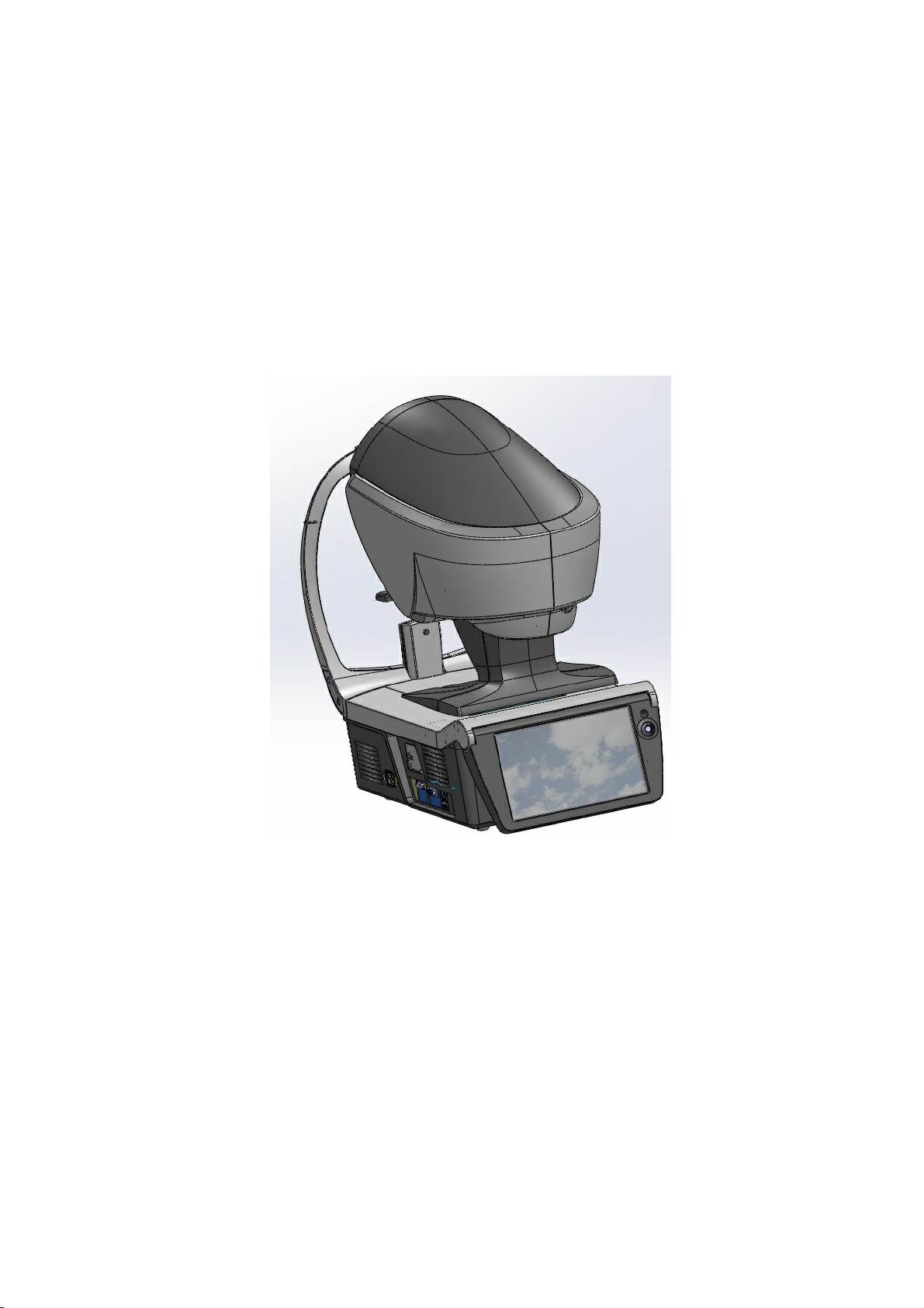
The Wave Analyzer Medica 700 is a multifunctional eye diagnostic device. There are several
operation modes combined in a single platform: aberrometer, autorefractometer keratometer,
corneal topographer, tonometer, pachymeter and retro illumination.
The wavefront aberrometer uses the Shack-Hartmann principle and is used as an advanced
autorefractometer that measures both lower and higher order aberrations of the refraction of
the eye. The aberrometer principle can measure the maximum pupil size of the pupil or the
default pupil size specified in the settings.
The corneal topographer uses 24 Placido disks to measure the shape of the anterior surface
of the cornea. It shows a detailed description of the shape of the cornea that can be
presented as corneal aberrometry. The placido rings also function as a keratometer.
The Scheimpflug pachymeter analyzes the anterior chamber of the eye (thickness of the
cornea, irido corneal angles, anterior chamber analysis and kappa angle) by illuminating it
with a slit of light and a camera using the Scheimpflug technique.
The air-puff non-contact tonometer measures the intraocular pressure.
Retro illumination imaging captures the light reflected from the eye to help identify dark spots
on camera. It is designed to take images of eyes with pupils of a diameter of 2-8mm
The device is fully automated and a number of different measurements can be performed by a
single command including alignment and focusing.
This guide explains how ophthalmologists, optometrists, and other eye-care professionals can
use the Wave Analyzer Medica 700. It includes instructions on how to setup, operate and
maintain the unit.
Caution: Federal (U.S.) Law restricts this device to sale by or on the order of a
physician.
1. 1 Indications for Use
Indications for Use
The Wave Analyzer Medica 700 is a multi-function diagnostic device combining wavefront aberometer,
corneal topographer, retro-illuminator, tonometer and pachymeter, indicated for:
Measuring the refraction of the eye giving both lower and higher order aberrations
Measurement of the shape of the cornea
Retro-illumination imaging of the eye
Measuring the intraocular pressure without contacting the eye for glaucoma evaluation.
Photographing the eye and taking images of the eye to evaluate the thickness of the central
cornea.Anterior chamber imaging.
Pupil image
Wave Analyzer Medica 700 User Guide
2
Page 9

Image of the cornea relative to the iris
Chapter
Description
Safety
Information about using the Wave Analyzer Medica 700
safely
Equipment and Installation
Equipment in the Wave Analyzer Medica 700 package,
description of the unit's parts, installing and setting up the
unit, turning the unit on and off
Overview of the Software
Introduction to the interface screens
Managing Patients
Adding patient records to the database; finding, modifying
and deleting existing patient records
Performing a Diagnostic
Preparing the patient and the unit for an exam procedure;
initiating and running the exam; working with the test
results
Managing the List of Test
Results
Opening, exporting, moving, and deleting test results that
are stored in the database
Managing the Database
Configuring the patient display, exporting and importing the
database, deleting patient records
General Actions and
Features
Additional information about the Wave Analyzer Medica
700 and its features - screen saver, password protection,
virtual keyboard, updating the software, and getting
assistance
Configuring the Unit
Information about configuring the unit's settings
What Should I Do If...?
Troubleshooting common problems
Maintenance
Routine maintenance procedures
Appendices
Technical specifications, conformation with international
standards, contact information
1. 2 About this Guide
This guide contains the following chapters:
6
10
20
89
Introduction
123
98
130
136
142
184
186
199
1. 3 Warning
This document contains confidential information that is the property of Manufacturer Any use,
reproduction or divulging of this material, in part or in whole, is strictly forbidden. This document
is provided for the exclusive use of Manufacturer employees and other authorized users.
The content of this user guide may be modified without warning. The images are not
contractual. Every reasonable effort has been made to ensure that its content is accurate. For
further information please contact a Manufacturer representative.
Wave Analyzer Medica 700 User Guide
3
3
Page 10

Copyright ©2018 Manufacturer All rights reserved.
Introduction
Wave Analyzer Medica 700 User Guide
4
Page 11

2. Safety
II
Page 12

Safety
Manufacturer provides sufficient information to ensure patient safety, avoid system
malfunctions, and prevent incorrect readings.
Manufacturer declines all responsibility for injury to patients or damage to equipment due to
ignorance of its safety instructions or in the event that they are not followed.
The safety information appears in the form of warnings and alert messages.
Important!
Never attempt to disassemble or reassemble the equipment. There are no user
serviceable parts in the device.
Do not modify the equipment in any way.
Repairs and maintenance must be carried out only by qualified service personnel.
Operators and patients should keep hands and body clear from moving parts on the
device.
This is a Class 1 laser product with an embedded Class 3R laser.
2. 1 Electricity
Important!
To avoid risk of electric shock or bodily injury, do not handle the electrical plugs with wet
hands.
To avoid risk of electric shock or fire, make sure the Wave Analyzer Medica 700's power
cord is not damaged before plugging it into an electrical outlet.
To avoid risk of electric shock, the power cord should be fully inserted in an outlet
equipped with a protective ground connection.
When connecting external devices such as a screen or printer, ensure that the device
conforms to IEC 60950-1:2005 Information Technology Equipment - Safety.
2. 2 Transport, Storage, and Handling
Important!
Transport the Wave Analyzer Medica 700 in its specially designed case.
Make sure the packing is firm and secure.
Do not subject the Wave Analyzer Medica 700 to strong vibrations. Shocks or violent
movements can cause malfunctions.
Wave Analyzer Medica 700 User Guide
6
Page 13

2. 3 Precautions During Use
Important!
Do not place or use the Wave Analyzer Medica 700 in direct sunlight.
Do not expose the Wave Analyzer Medica 700 to excessive dust or humidity.
Do not place the Wave Analyzer Medica 700 in a hot air current (e.g. above a heater).
Do not obstruct the ventilation vents.
Never place the Wave Analyzer Medica 700 close to the following types of equipment
which can perturb the reception of commands from the remote control:
o Halogen lamp (direct or indirect)
o Fluocompact lamp
Keep the screen surface clean. Protect it from dust, fingerprints, and shocks.
When you switch off the Wave Analyzer Medica 700, wait at least 5 seconds before
switching it on again.
Safety
Wave Analyzer Medica 700 User Guide
7
7
Page 14
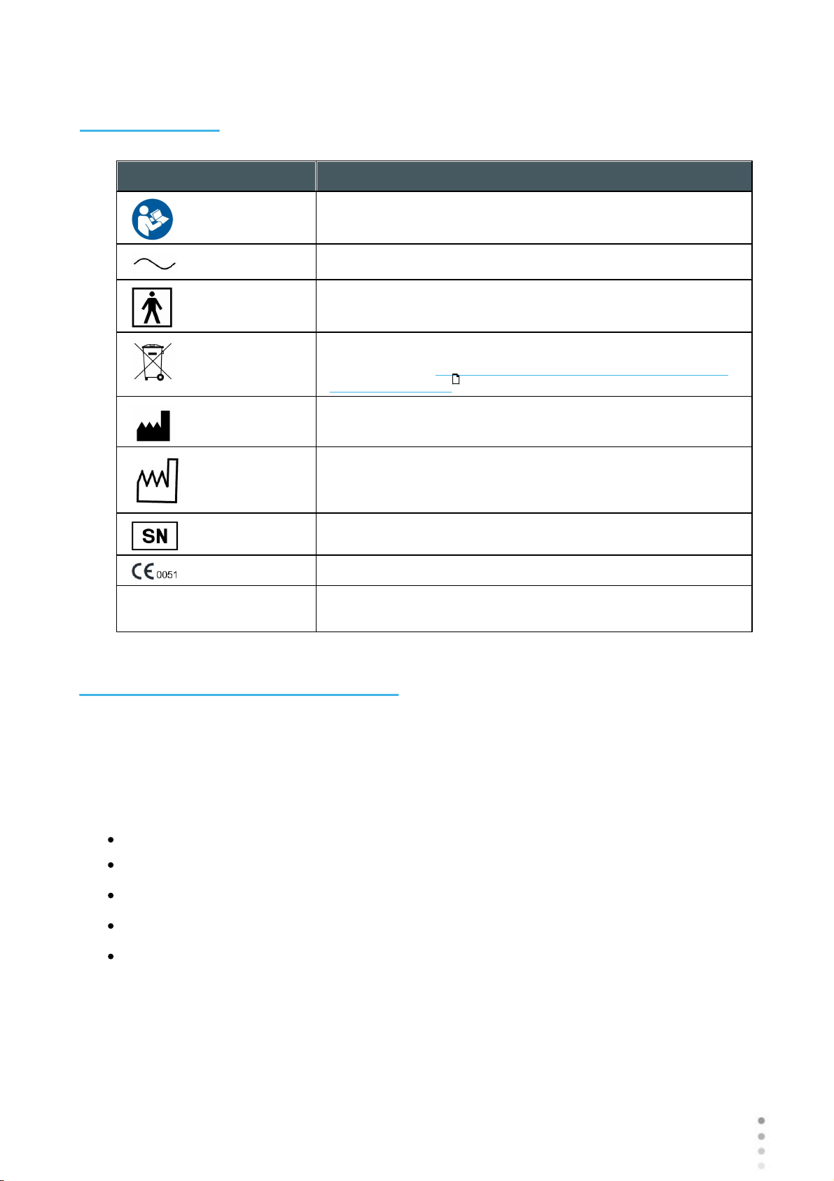
2. 4 Symbols
Symbol
Description
Important: consult the documents supplied with the
equipment
Alternating current
Type BF
The equipment must be returned to the manufacturer for
scrapping (see Waste Electrical and Electronic Equipment
(WEEE) Directive )
Manufacturer
Year of Manufacturing
Serial Number
Compliance with Medical Device Directive 93/42/EC
Rx Only
Caution: Federal (U.S.) Law restricts this device to sale by or
on the order of a physician.
Safety
206
2. 5 Network Configurations
The safety of the Wave Analyzer Medica 700 has not been verified when connected to ITnetworks including other equipment and may result in previously unidentified risks to patients,
operators or third parties. Therefore, we recommend that every user should identify, analyze,
evaluate and control these risks. Changes to the IT-Network may introduce additional analysis
to confirm the safety of the device, such as changes including, but not limited to:
Changes to Network Configuration
Connection of additional items
Disconnection of items
Update of equipment
Upgrade of equipment
Wave Analyzer Medica 700 User Guide
8
Page 15

3. Equipment and Installation
III
Page 16
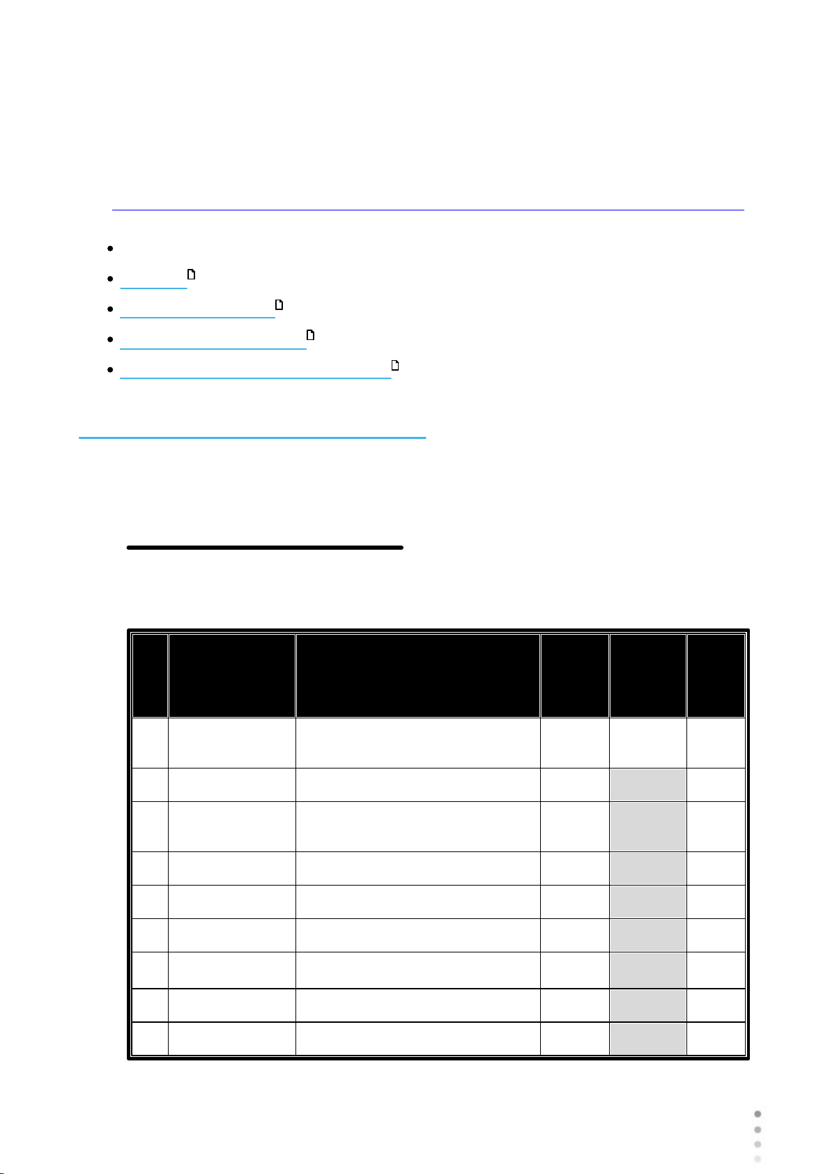
List of Equipment Supplied
I
t
e
m
Part No.
Description
Quan
tity
Serial
No.
Pre
sent
1
Wave Analyzer Cornea/Medica
70012
40150073-00
Nylon Bag
1
N/A
3
----------------
Desiccant Bag (Inside the nylon
cover)
2
N/A
4
30069141
European Power Cord
1
N/A5415059
U.S Power Cord
1
N/A641000014-00
Chin rest Paper Pack
1
N/A
7
41000015-00
Chin rest Metal Pins
2
N/A
8
41000104-00
Paper Rolls
2
N/A
9
-----------------
Band
2
N/A
Unit Parts
11
Equipment and Installation
Installation Procedures
Turning the Unit On and Off
Setting up the Username and Password
16
17
18
3. 1 List of Equipment Supplied
PACKING LIST
Wave Analyzer Cornea/Medica 700
Wave Analyzer Medica 700 User Guide
10
Page 17
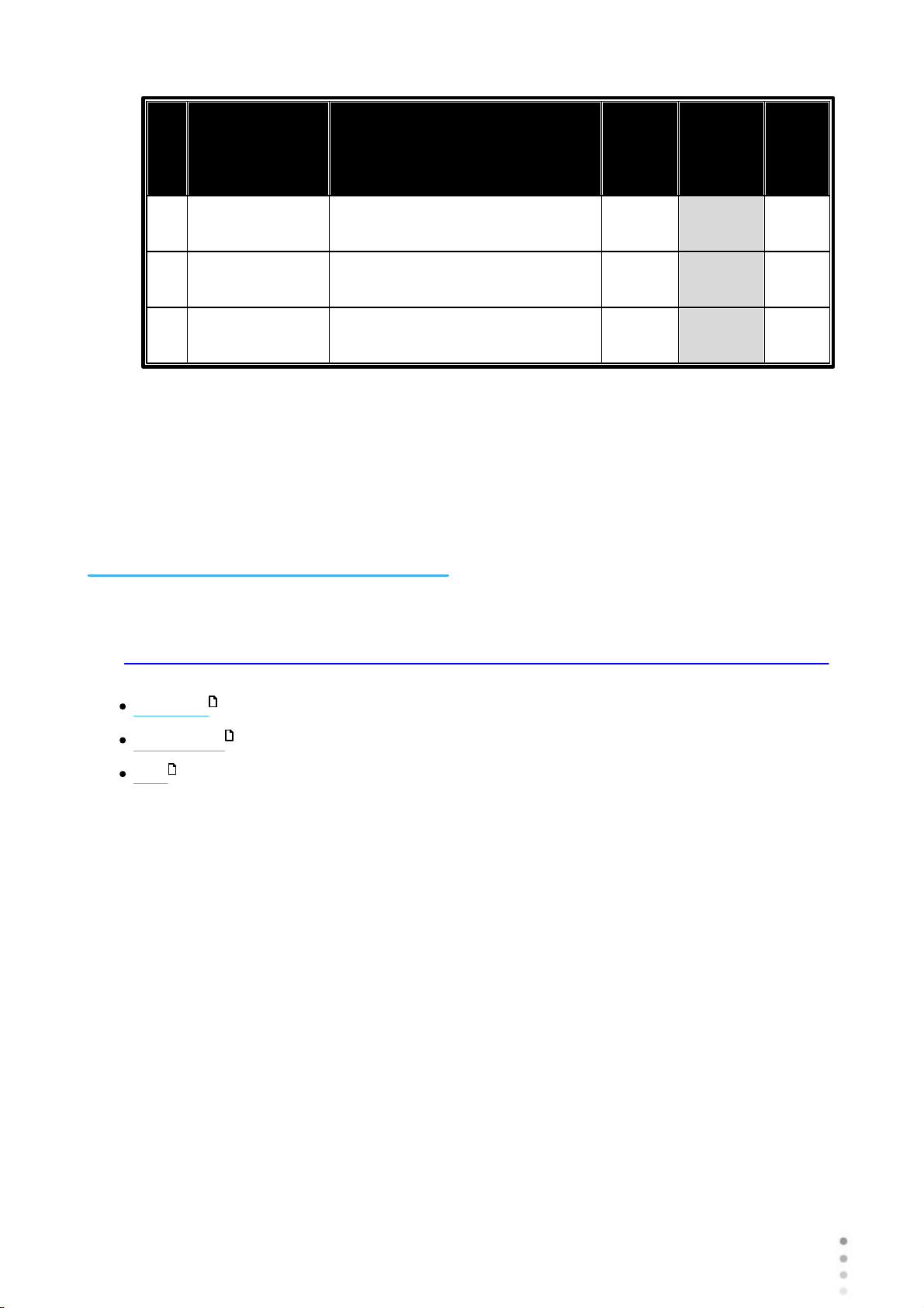
I
t
e
m
Part No.
Description
Quan
tity
Serial
No.
Pre
sent
1030204034-00
Dust Cover
1
N/A
11UM3020000100
User Manual (CD)
1
N/A
12WI-30201002-
00
Packing Instructions For Wave
Analyzer
1
N/A
Date: __________________
Equipment and Installation
Approved by (Name, Signature): _____________________________________________
3. 2 Description of the Device
User Side
Patient Side
Side
12
13
15
Wave Analyzer Medica 700 User Guide
11
11
Page 18
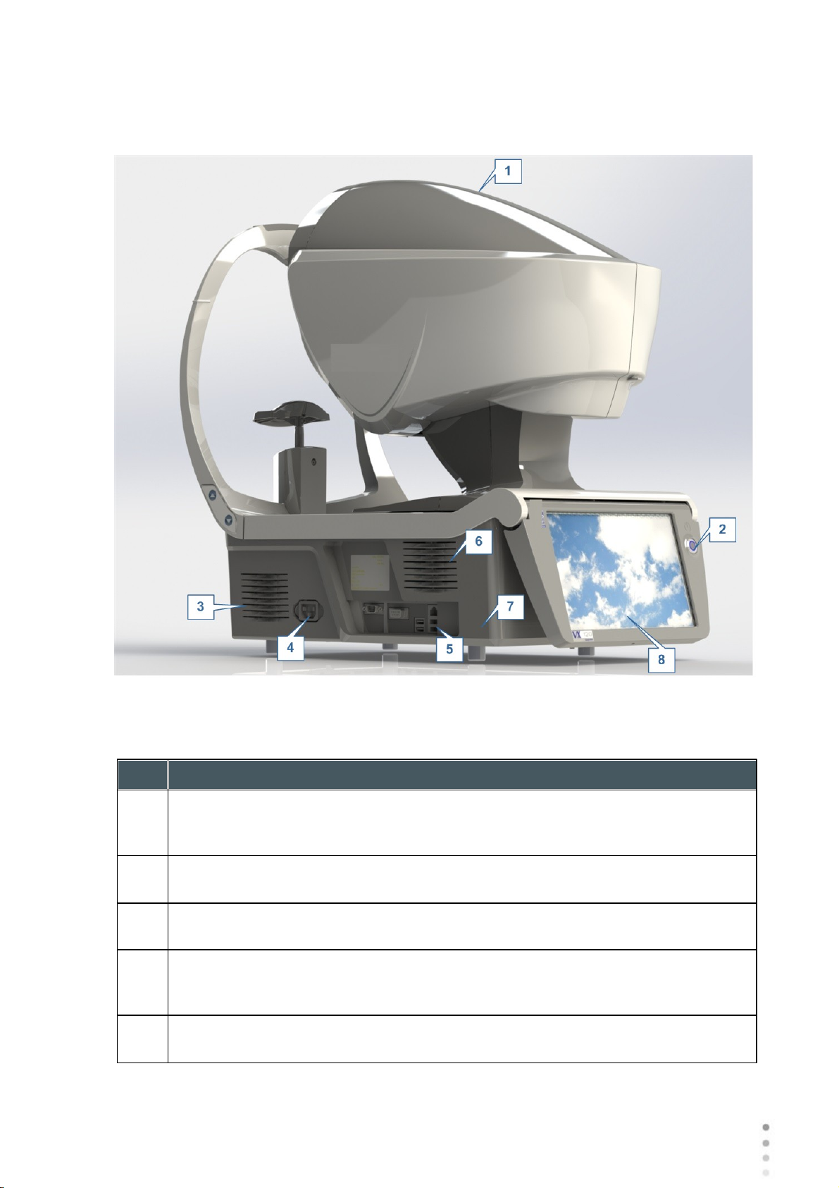
User Side
No
Description
1
Optical-measurement head
Contains the hardware used to perform all of the measurements during patient
diagnostic exams.
2
On/Off switch
Shuts down the machine
3 &6Ventilation Slots
4
Power-cable connector
Connect the supplied power cable to this connector; plug the other end of the cable
into a standard electrical outlet.
5
Connectors for external devices
See the table below for a list of the available connectors.
Equipment and Installation
Wave Analyzer Medica 700 User Guide
12
Page 19
No
Description
7
Base
Contains the unit's computer and other electronics
8
LCD touch screen
The following connectors for external devices are available:
Port Type
Uses
USB (4 ports)
Connect an external hard drive or flash drive to export data from
the unit's database and/or to import data to the unit.
Connect a keyboard to use instead of or along with the virtual
keyboard .
Connect a mouse to use instead of or along with the touch screen.
Connect a printer to print on standard printer paper.
Network (2 ports)
Connect a network cable to connect the unit to a LAN. You will then
be able to export and import data to and from computers on the LAN.
Serial port (RS-
232)
Connect a compatible optometric device, such as a phoroptor, to the
unit
VGA port
Connect an external monitor to the unit
137
Equipment and Installation
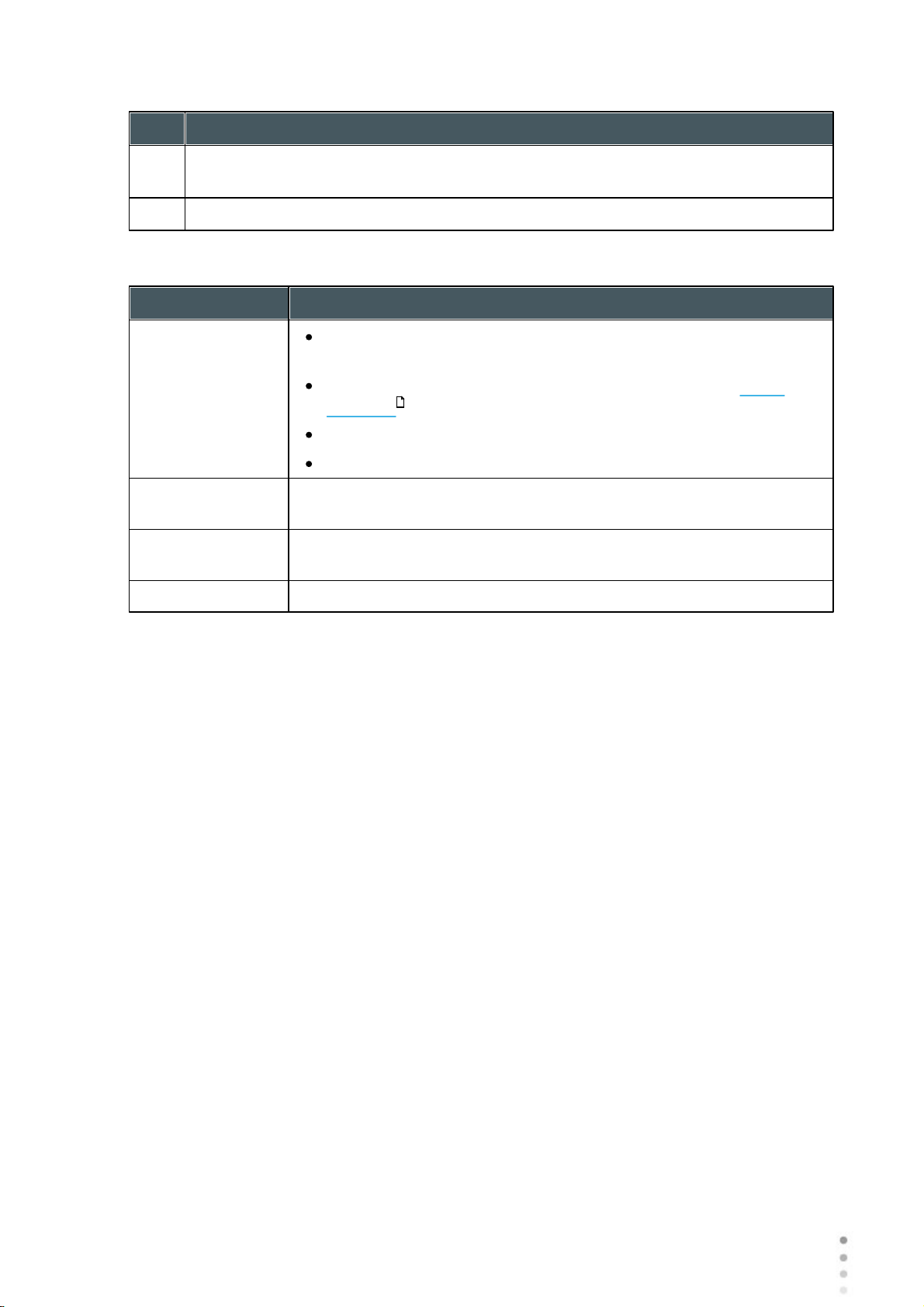
Patient Side
13
Wave Analyzer Medica 700 User Guide
13
Page 20
Equipment and Installation
No
Description
1
Headrest
The patient should lean their forehead on the headrest during all diagnostic
procedures.
2
Chin rest
The patient should lean their chin on the chin rest during all diagnostic procedures.
Wave Analyzer Medica 700 User Guide
14
Page 21
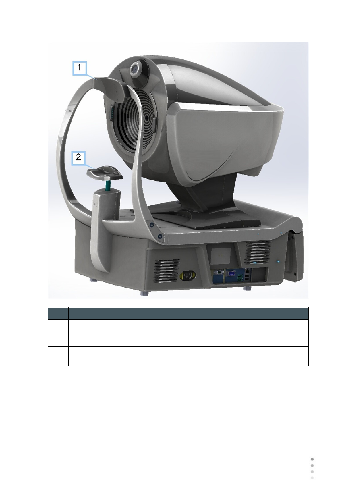
Side
Wave Analyzer Medica 700 unit, printer side
No
Description
1
Ventilation slot
2
Printer LED
Printer status indicator:
LED off: Printer is turned off.
LED on (not flashing): Printer is turned on and ready to print.
LED flashing: Printer is on, but either there is no paper or there is a malfunction
3
Printer paper-feed button
Press to feed a small amount of paper through the paper slot (#5).
4
Paper slot
Paper is fed through this slot when it is loaded.
5
Paper-roll compartment
For paper-loading instructions, see Loading Paper into the Printer .
Equipment and Installation
Wave Analyzer Medica 700 User Guide
15
17
15
Page 22
3. 3 Installation Procedures
Equipment and Installation
Site Requirements
Opening the Box
Electrical Connection
Loading Paper into the Printer
16
16
17
17
Site Requirements
The Wave Analyzer Medica 700 unit should be placed on a clear table or desktop close to a
power outlet. The unit should not exposed to direct light on the patient side. Better results will
be obtained if the unit is located in a room with limited illumination.
Unpacking the Unit
To unpack the unit:
Remove the straps around the box.
Open the carton with care.
Lift the protective top cover to uncover the accessories listed in the packing list.
Remove the accessories to uncover the Wave Analyzer Medica 700 unit, which is
packed in a protective plastic bag.
Important!
Do not grab or hold the screen when extracting the device from the box. Do not lift the
device by the head (#1 in Description of the Device ) as this may damage the motors.
12
Take the Wave Analyzer Medica 700 out of the box and put it on the table.
Lift the protective plastic bag to uncover the device.
Wave Analyzer Medica 700 User Guide
16
Page 23

Electrical Connection
To connect the unit to an electric outlet:
Check that the power supply voltage corresponds to that required by the equipment (see
the identification label on the back of the unit).
Equipment and Installation
Insert the power connector of the power cord into the power-cable connector on the unit
(#4 in the illustration of the user side ).
Connect the power plug to a wall outlet.
12
Loading Paper into the Printer
If the paper roll is used up, the printer LED indicator blinks.
To insert a paper roll into the printer:
Lift the handle in the middle of the paper compartment and pull the cover down.
If an empty paper roll is in the printer, remove it.
Insert the new roll with the end of the paper on the top of the roll.
Feed the paper into the slot at the top of the compartment.
Push the paper-compartment door closed.
3. 4 Turning the Unit On and Off
To turn the unit on:
Press the On/Off switch (#2 in the illustration).
To turn the unit off:
From the software, in the Home Screen , select the Turn Off button.
-OR-
From the software, in the Configuration screen , select the Turn Off button.
-OR-
On the unit, press the On/Off switch.
Regardless of which of these methods you use to turn off the unit, it shuts down. If you
turn the unit off using the software, the head moves back to its default position. It is
important to ensure that the head is in its default position before moving the unit.
Notes:
If you intend to pack and/or move the device, you must turn it off using the software.
20
142
17
Wave Analyzer Medica 700 User Guide
17
Page 24

Equipment and Installation
3. 5 Setting up the Username and Password
The first time you turn on the device, you will get a request to set your username and password
in order to keep your device secure from unauthorized persons. Subsequently, the device will
require the username and password each time you turn on the unit.
1. Select the user Diagnostic.
2. Enter this default password:
user
The device will not be accessible if the username and password have not been supplied, or if
they have been supplied uncorrectly. If you do not remember your username and password
correctly, contact an authorized technician for assistance.
Wave Analyzer Medica 700 User Guide
18
Page 25

4. Overview of the Software
IV
Page 26
Overview of the Software
Home screen
Home Screen
Patient Screen
Measure Screen
Results Screen
20
21
24
36
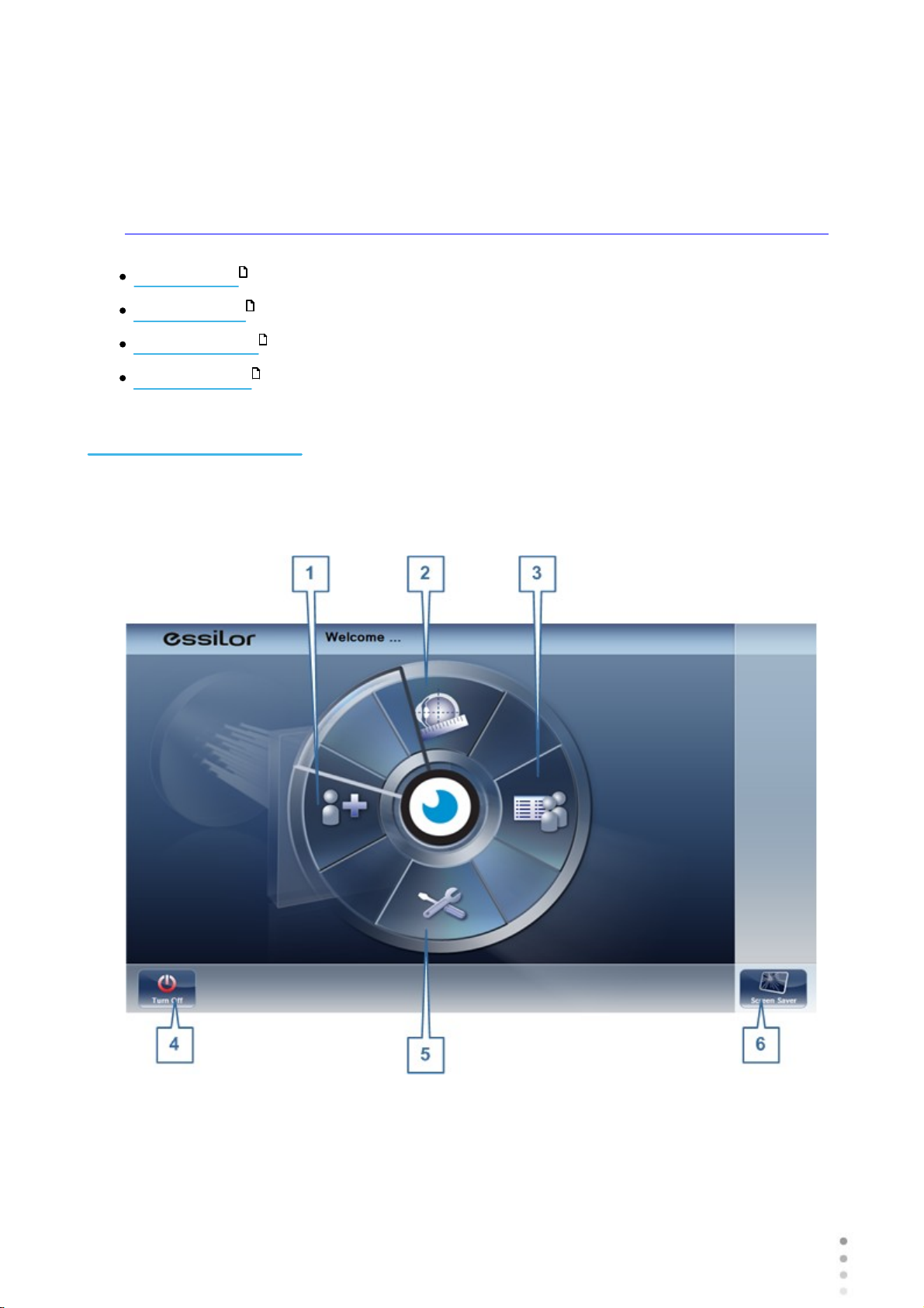
4. 1 Home Screen
The Home screen is the main menu of the Wave Analyzer Medica 700. It gives you access to
all of the functional screens of the interface.
Wave Analyzer Medica 700 User Guide
20
Page 27
Overview of the Software
No
Description
1
Add Patient button
Opens the Patient screen with the Patient Information dialog box open so
that you can begin entering patient information immediately.
2
Measurement screen button
Opens the Measurement screen without a patient selected. The results will be
saved temporarily with an automatically generated ID number.
3
Open Patient screen button
Opens the Patient screen and displays the list of patients
4
Turn Off button
Shuts the unit down. See Turning the Unit On and Off .
5
Configuration Screen button
Opens the Configuration screen
6
Screen Saver button
Turns on the screen saver.
21 89
24
21
17
142
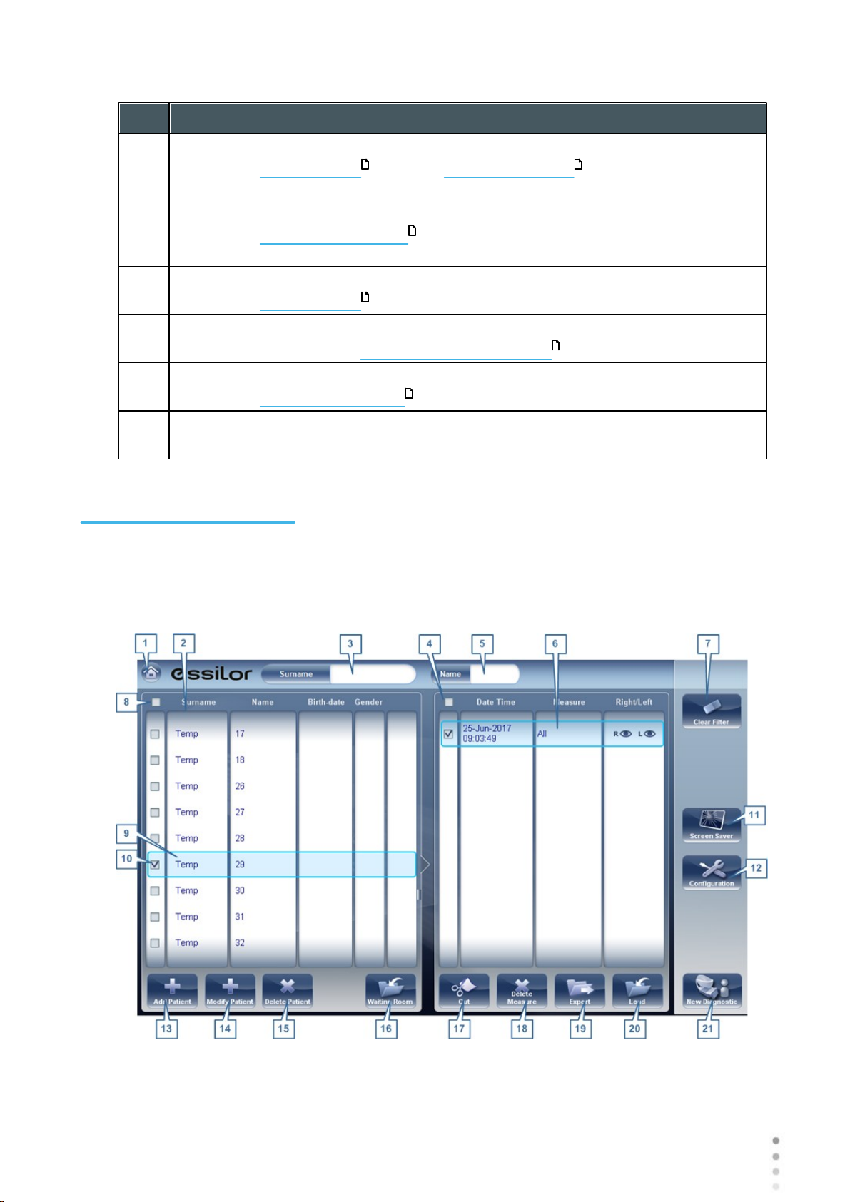
4. 2 Patient Screen
The Patient screen gives you access to the patient database. You can create new patient
records, modify existing patient information, view stored test results, and initiate a new
diagnostic procedure for a selected patient from this screen.
21
Wave Analyzer Medica 700 User Guide
21
Page 28
Overview of the Software
No
Description
1
Home button
Opens the Home screen .
2
Patient list
List of patients in the database; drag your finger (or mouse) over the entries to
scroll up or down.
3
Surname filter
Enter one or more letters. The list of patients is filtered and only displays patients
whose last names begin with the specified sequence of letters.
4
Mark all measures
Mark the check boxes of all the displayed measures. Cut (#16 ) and Delete
Measure (#17 ) are applied to all measures whose check boxes are marked.
5
Name filter
Enter one or more letters. The list of patients is filtered and only displays patients
whose first names begin with the specified sequence of letters.
6
Measure list
List of test results for the selected patient; drag your finger (or mouse) over the
items to scroll up or down.
7
Clear Filter button
Clear all patient filters and display all the patient records in the database.
8
Mark all patients
Mark the check boxes of all the displayed patient records. Delete Patient (#15 )
is applied to all patients whose check boxes are marked.
9
Selected patient record
Blue border indicates a patient record is selected. The measures in the Measure
list belong to the selected patient. In addition, Modify Patient (#14 ) opens the
patient data for the selected patient.
10
Marked check box
Example of a marked check box
11
Screen Saver button
Turns on the screen saver.
12
Configuration button
Opens the Configuration screen .
13
Add Patient button
Opens the Patient Information dialog box.
14
Modify Patient button
Opens the patient data of the selected patient (#9 )
Note: This button is only available when a patient is selected in the list.
15
Delete Patient button
Deletes all the patient records whose check boxes are marked (#10 )
Note: This button is only available when the check boxes of one or more patients
are selected in the list.
20
21
21
21
21
142
89
21
Wave Analyzer Medica 700 User Guide
21
22
Page 29
Overview of the Software
No
Description
16
Waiting Room
This button displays all of the patients imported via XML For more information, go
to the Waiting Room.
17
Cut button
Removes all the measures whose check boxes are selected from the selected
patient record, and saves them in the clipboard so that they can be pasted into a
different patient record.
Note: This button is only available when the check boxes of one or more
measures are selected.
Note: When Cut is selected, the button is replaced with a Paste button. Select the
patient record in which you want to insert the cut measures and then select Paste
to insert them.
18
Delete Measure button
Deletes all the measures whose check boxes are marked
Note: This button is only available when the check boxes of one or more
measures are selected.
19
Export button
Exports the selected measures to an external file and/or prints the measurement
results or screenshot
Note: This button is only available when a measure is selected.
20
Load button
Opens the selected measure in the Results screen .
Note: This button is only available when a measure is selected.
21
New Diagnostic button
Initiates a new diagnostic procedure for the selected patient. The results of the
diagnostic are automatically stored in the patient's record.
92
36
When exporting (clicking on the no. 18 Export button) from the patient screen
the following pop-up will appear:
23
Wave Analyzer Medica 700 User Guide
23
Page 30

Overview of the Software
No
Description
1
Data Transfer
Options for transferring data from the device to other devices
2
External Device
Exporting data from the Wave Analyzer Medica 700 to another device
3
Ticket
Allows printing the data on a ticket in the device's internal printer
4
Print Screen
Select to print a screenshot of the summary screen, this requires a connection to
an external printer.
5
Cancel
Cancels your selection.
6
Send
Confirms the selection and performs the transfer
The export popup from the patient screen enables you to export data via an external device.
Select the checkbox next to external device, and then press SEND. To print a screencapture
of the screen you are viewing, select Print Screen.
4. 3 Measure Screen
The Measure screen is used to select, initiate, and follow the progress of diagnostic tests.
Wave Analyzer Medica 700 User Guide
24
Page 31

Overview of the Software
Measure screen before measurement begins
No
Description
1
Home button
Opens the Home screen .
2
Patient
Name (or ID) of current patient.
Note: If no patient was selected before the Measure screen was opened, a
temporary name is generated by the system by combining "Temp" with a
number (e.g., "Temp 1184").
3
Up arrow
Raise the unit's head so that it aligns better with the patient's eyes.
4
Message field
A text field in which the system displays messages to you, such as instructions
for you to give to the patient or information about the testing process.
Before a Measurement
When you first open the Measure screen, before you start running the diagnostic, the screen
looks like this:
20
Wave Analyzer Medica 700 User Guide
25
25
Page 32

Overview of the Software
No
Description
5
Left-eye indicator
When active, indicates that the head is aligned with the patient's left eye
Note: In the illustration above, the right-eye indicator is active (see #8 below)
and the left one is not active.
6
Diagnostics available
List of available diagnostic tests. Drag up and down on the list to scroll it, if
necessary, and select the type of test you want to perform. Go to Diagnostics
for a complete list of available options.
7
Input arrow
Using this Input arrow is a quick way to change a "Temp patient" into a patient
that already exists in your XML database. Simply click the blue arrow to
load patient details from your database. If the arrow is greyed out, , it
means that the input folder is empty, and there is no information available for
loading. For more information, go to Importing XML data.
8
Eye selector
Select the eye or eyes to be tested.
9
Right-eye indicator
When active, indicates that the head is aligned with the patient's right eye
Note: In the illustration above, the right-eye indicator is active, and the left one is
not (see #5 , above)
10
Camera view
Shows the image that is visible through the camera
Select any spot in the image to move the unit's head to align that spot with the
cross hairs in the center of the image.
11
Left arrow
Move the unit's head to the left so that it aligns better with the patient's eyes.
12
Position
Select Adult to move the head and chin rest into the default positions for adults,
or select Child to move them into the default positions for children.
Once you have done this, you can fine-tune the head and chin-rest positions
using the the chin-rest controls (#12 ), the arrows (#3 , #10 , #16 , and
#17 ).
13
Chin Rest
Raise or lower the chin rest.
25
146
91
25
25 25 25 25
25
Wave Analyzer Medica 700 User Guide
26
Page 33

Overview of the Software
No
Description
14
Parameters
Open a dialog box in which you can change the number of times WF and Tono
teststest will be performed during this diagnostic.
Note: If the WF and Tono tests are not included in this diagnostic, changing the
values in the dialog box will have no effect.
15
Cancel
Cancel the measurement procedure and return to the previous screen.
16
Go
Begin the diagnostic test.
17
Down arrow
Lower the unit's head so that it aligns better with the patient's eyes.
18
Right arrow
Move the unit's head to the right so that it aligns better with the patient's eyes.
19
Measures to be performed
Indicates which measurement procedures will be performed for the diagnostic
selected in the Diagnostics list (#6 ).
25
Wave Analyzer Medica 700 User Guide
27
27
Page 34

Overview of the Software
No
Description
1
Demo Puff
Select to demonstrate tono air puff
2
WF Measurements
The number of Wavefront measurements to perform
3
Tono Measurements
Select to modify number of tono measurements to perform
When clicking on Parameters (no. 13 above), the following dialog box is displayed:
Wave Analyzer Medica 700 User Guide
28
Page 35

Overview of the Software
No
Description
4
Reading Distance
The distance to perform the near vision test, from 30-60cm
5
Cancel
Closes the dialogue box without saving
6
Save
Saves the user's preferences
Measure screen during measurement process
No
Description
1
Home button
[Button not available when a diagnostic is in progress]
During a Measurement
After you select Go to begin the selected measurement procedure, the Measure screen
shows information about the measurement process. During the measurement process, you
can adjust the unit's head and chin rest as you would before the process began. You can also
speed the measurement process up, skip parts of the test, or stop the test.
Wave Analyzer Medica 700 User Guide
29
29
Page 36

Overview of the Software
No
Description
2
Patient
Name (or ID) of current patient.
Note: If no patient was selected before the Measure screen was opened, a
temporary name is generated by the system by combining "Temp" with a number
(e.g., "Temp 1184").
3
Up arrow
Raise the unit's head so that it aligns better with the patient's eyes.
4
Message field
A text field in which the system displays messages to you, such as instructions
for you to give to the patient or information about the measurement process.
5
Left-eye indicator
When active, indicates that the measurement is currently being performed on the
patient's left eye.
Note: In the illustration above, the right-eye indicator is active (see #9 below)
and the left one is not active.
6
Sensor view
During WF measurement, the Shack-Hartmann image is displayed in this area.
7
Measure in progress
Indicates that this measure is currently being performed.
8
Completed test
Indicates that the measure was already performed.
9
Right-eye indicator
When active, indicates that the measure is currently being performed on the
patient's right eye.
Note: In the illustration above, the right-eye indicator is active, and the left one is
not (see #5 , above).
10
Camera view
Shows the image that is visible through the camera.
Note: To manually center the image, select the spot that should be in the center
of the image. The unit's head moves so that that spot is aligned with the cross
hairs in the center of the image.
11
Left arrow
Move the unit's head to the left so that it aligns better with the patient's eyes.
12
Position
Select Adult to move the head and chin rest into the default positions for adults,
or select Child to move them into the default positions for children. The default
PD is also set appropriately for adults or children when you select one of these
options.
Once you have done this, you can fine-tune the head and chin-rest positions
using the the chin-rest controls (#13 ) and the arrows (#3 , #11 , #17 ,
and #18 ).
25
25
25 25 25 25
25
Wave Analyzer Medica 700 User Guide
30
Page 37

Overview of the Software
No
Description
3
Chin rest
Select the arrows to raise or lower the chin rest.
14
Quick mode
Speed the measurement process up.
This option is only available during WF measurements. It is useful if the patient
has trouble sitting still for a long period of time. The results of the measurement
may be slightly less accurate than they would be in standard mode.
15
Skip
Cancel the current stage of the measurement procedure and proceed to the next
stage. For example, if a measurement is being performed on the patient's left
eye, selecting this button would discontinue the measurement on that eye, and
begin measuring the other eye.
16
Stop
Stop the entire measurement process. When this button is selected, the
measurement procedure is aborted, and the pre-test Measure screen is
displayed.
17
Down arrow
Lower the unit's head so that it aligns better with the patient's eyes.
18
Right arrow
Move the unit's head to the right so that it aligns better with the patient's eyes.
19
Measurement status
Indicates which measures are included in the current measurement procedure,
and shows the status of those measures that have already been completed.
25
Immediately after the measurement, the Ringer edit screen will be displayed (only if a
topography measurement has been made). In this screen, the user can edit the rings detected
by the device and those rings that were wrongfully detected.
31
Wave Analyzer Medica 700 User Guide
31
Page 38

Overview of the Software
Ringer Screen
Wave Analyzer Medica 700 User Guide
32
Page 39

Overview of the Software
No
Description
1
Erase
To erase individual rings in the topo map image select "Erase". A list of ring
positions opens. Select the position of the ring you would like to erase, and then
move the cursor over it, and only ring in the selected position will be erased.
Note, the outer rings are in higher positions, from position 24 and downwards,
while the inner ring is position 1.
Note: If you erase more than 10% of the topography rings, you may reduce
the accuracy of the results.
2
Add
Select the position number of the ring (shown in blue), then trace the ring in that
position, the device "draws" a new ring. Note, rings can only be drawn if the topo
image is relatively clear.
3
Auto
Allows deleting rings by touching the screen. This is the default mode.
4
Undo
Undo the modifications
5
Retake
Retakes the measurement
6
Continue
Validates the modifications that were done and computes the topography map
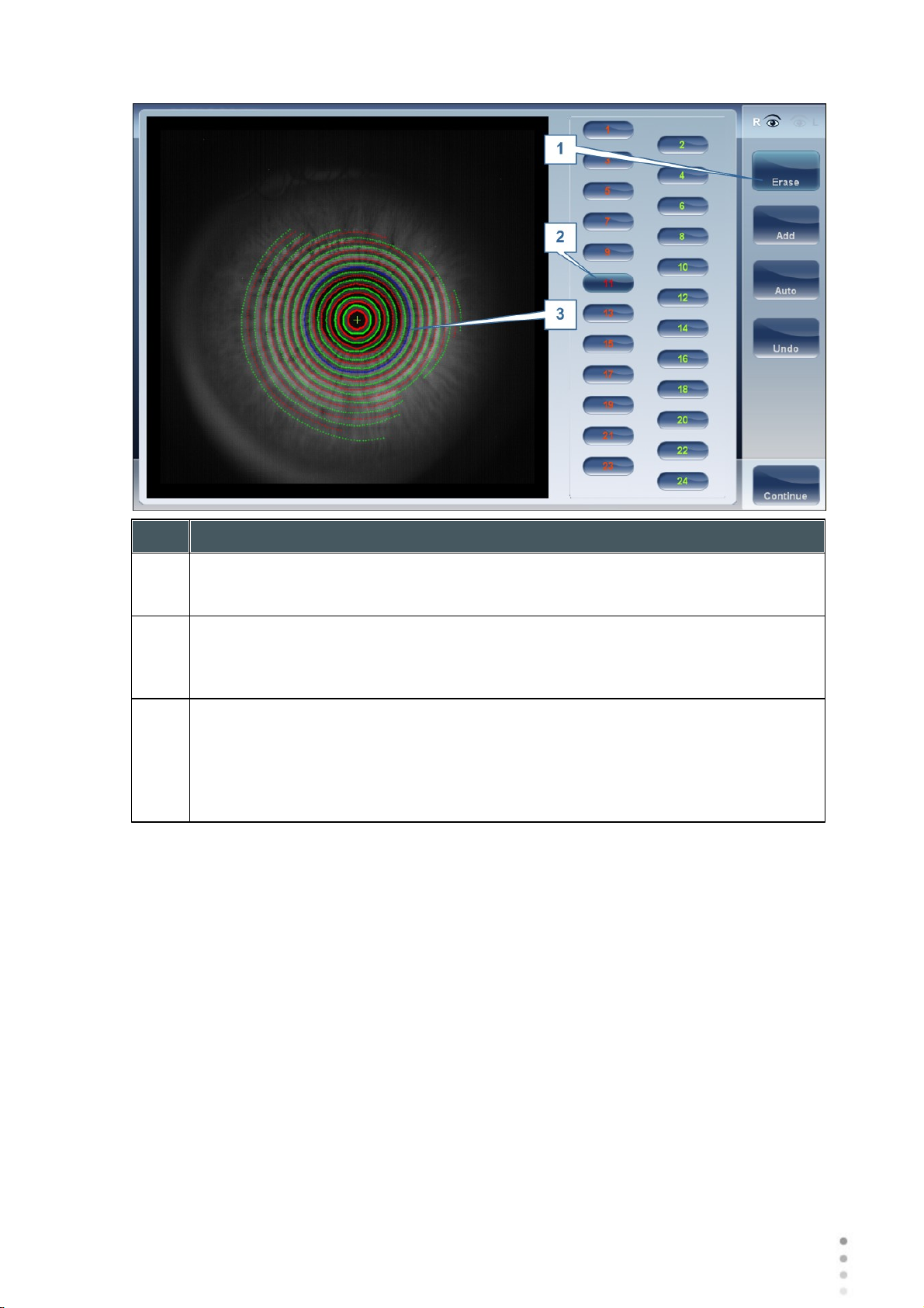
Editing the Ringer
If you select ADD or ERASE from the menu above, the following screen appears:
Wave Analyzer Medica 700 User Guide
33
33
Page 40
Overview of the Software
No
Description
1
Operation buttons
Select these buttons to add, erase, undo, or continue.
2
Ring Positions
Select the position of the ring that you would like to modify. Once selected the
ring will appear blue.
3
Selected Ring
Once you have selected a Ring in #2, it will appear blue and it can be erased/
added to. To erase the ring, move the cursor over the areas that you would like to
be erased. To add to the ring, move the cursor over the area you would like to
draw. In the image above, the ringer selected is in position number 11.
To erase rings at will, select AUTO and then slowly move the cursor over the rings you want
erased. This action can erase several rings at a time. After modifying the the Rings, select
Continue, and the changes will be saved.
Note: only changes done immediately after the examination will be saved.
Repeating a measurement
After the results screen is displayed, it is possible to repeat the measurement by clicking the
"Measure" button (See: Results Screen). After clicking the Measure button, the following
dialogue box is opened:
Wave Analyzer Medica 700 User Guide
34
Page 41

Overview of the Software
No
Description
1
Select all
Selects all measurements for both eyes
2
Right
Measurements for the right eye
3
Left
Measurements for the left eye
4
Both
Measurements for both eyes
5
List of measurements
The list of measurements that were performed previously and that can be
repeated
6
OK
Validates the selection and performs the new measurement according to the
selection
Select the measurements that you want repeated, and continue with the measurement as
normal.
Wave Analyzer Medica 700 User Guide
35
35
Page 42

4. 4 Results
Overview of the Software
The Results screen displays the results of diagnostic measurements. It opens when a
diagnostic test is completed or when stored test results are loaded from the Patient screen .
The Results screen initially displays the Summary tab , which gives a condensed view of
38
21
the results. The other tabs of the Results screen show certain aspects of the results in greater detail, and are listed below
Overview of Summary Screen
Maps Tab
Data Tab
ACA Tab
Opacity Tab
Coeff. Aberrations
Simulation
47
61
66
70
72
77
37
CL Fitting
82
Wave Analyzer Medica 700 User Guide
36
Page 43

Overview of the Software
Results screen: standard elements
No
Description
1
Home button
Opens the Home screen .
2
Patient name, date and time
The surname and first name of the patient, and the date and time of the
measurement
3
Left eye Indicator
Results displayed on this side of the screen are those of the left eye
4
VD
Vertex distance, this button displays the distance of the refraction measurement, it
allows you to toggle between the default and zero.
5
D/mm button
This button allows you toggle between displaying the results in millimeters and
diopters.
Overview of the Summary Screen
The Results screen is dynamic, and may have a different layout and data according to the
diagnostic chosen. This is general an overview of a possible results screen:
20
Wave Analyzer Medica 700 User Guide
37
37
Page 44

No
Description
6
Measure button
Opens the Measure screen , with the patient's name selected, so that you can
perform additional tests that were not included in the current diagnostic.
7
Export button
Exports the test results to a file on an external device and/or prints the test results.
To view more export options, go to Exporting from the Results Screen .
8
Exit button
Closes the Results screen, and displays the default screen (which is selected in
the configuration settings ).
9
Tabs
This section may have fewer tabs, depending on the diagnostic chosen. Select a
tab to display the topic in greater detail.
Dynamic Summary Tabs
Summary Tab, ALL diagnostic
Overview of the Software
25
126
160
The Dynamic Summary tab is displayed by a default opening of the Result screen. It gives a
condensed view of the results.
Note: If results for a particular type of test are not available, the result fields are left blank. This
chapter will show some of the various summary tabs and their descriptions.
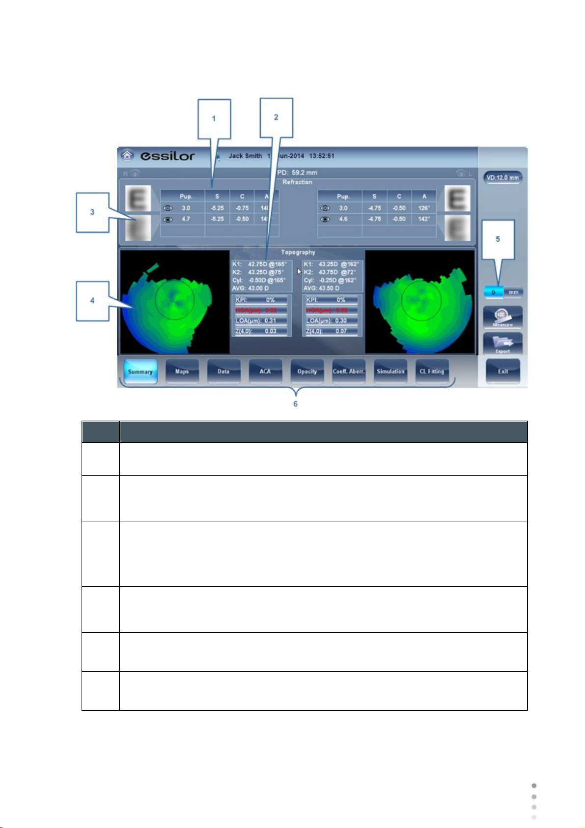
Summary tab for All diagnostic:
Wave Analyzer Medica 700 User Guide
38
Page 45

Overview of the Software
No
Description
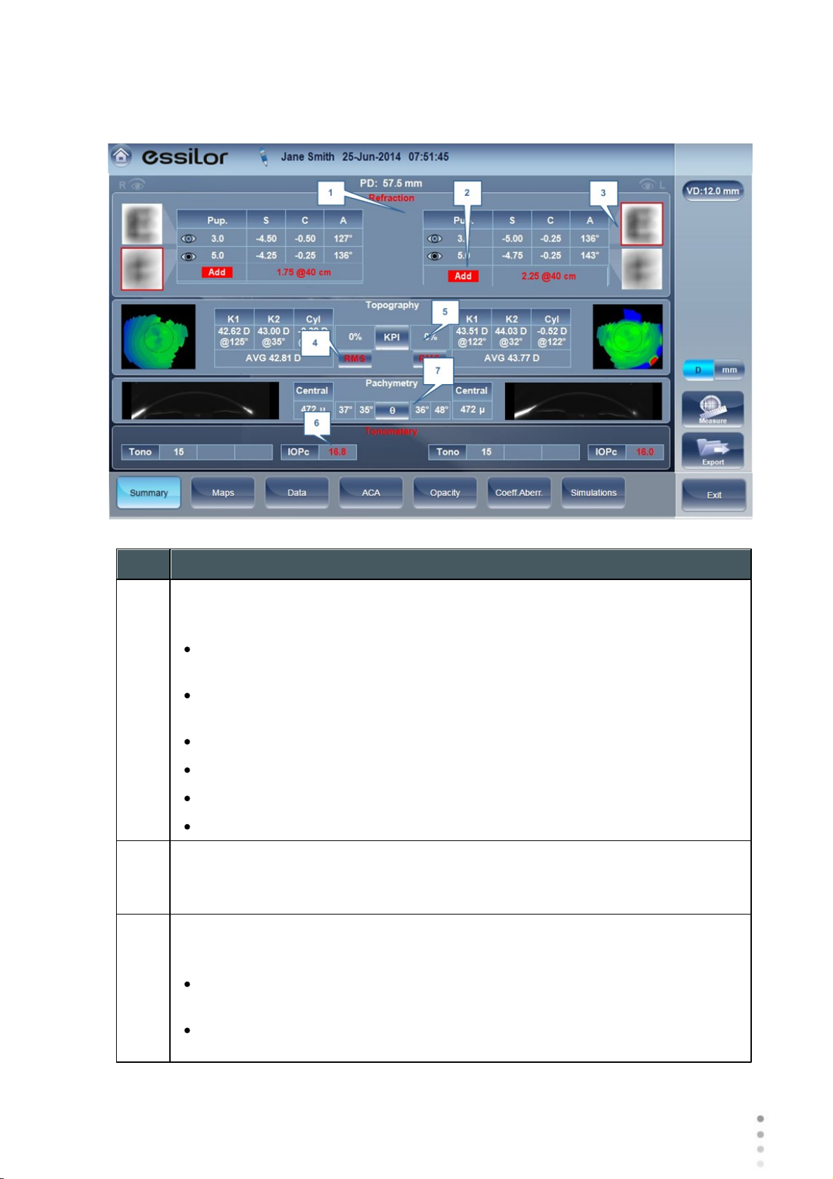
1
PD
Patient's pupillary distance (if available).
2
Refraction
Displays the photopic and mesopic refractions, with the pupil sizes. The image
shows the Photopic (above) and Mesopic (below) simulation of vision. The
clarity of the E indicates how well the patient sees from the eye under photopic or
mesopic conditions. Double-tap (or double-click) the E to open a visual acuity
simulation for daytime / nighttime vision.
3
Add
Add displays the near vision addition and distance (in cm) it was measured at.
4
Topography
Displays the topographic map of the eye as well as the keratometry values.
Double-tap (or double-click) to open the topography map sub-tab for the eye.
5
Pachymetry
Displays a Scheimpflug image (if Multi Slit pachy taken) of the cornea as well as
the thickness of the cornea at its center. Double-tap (or double-click) on image to
open the ACA sub-tab for the eye.
6
Tonometry
Displays the Glaucoma evaluation results which include: the tonometry test results
in PO mm/Hg,the average of the tonometry test results, and the irideo angles and
the anterior chamber depth results. In addition it displays the adjusted tonometry
results which is based on formulas selected in the settings menu. Double-tap (or
double-click) to open the Tonometry Tab sub-tab.
7
Right-eye indicator
Indicates that the test results on this side of the screen are for the right eye.
65
39
Wave Analyzer Medica 700 User Guide
39
Page 46
Summary Tab for C.L. Fitting:
No
Description
1
Refraction
Displays the photopic and mesopic refractions, with the pupil sizes.
2
Keratometry
Displays the keratometry readings, KPI values (Keratconus Index), and High Order
and Low Order aberrations
3
E Simulation
The clarity of the E indicates how well the patient sees from the eye under
photopic or mesopic conditions. Double-tap (or double-click) the E to open a visual
acuity simulation for daytime / nighttime vision.
4
Topography
Displays the topographic map of the eye Double-tap (or double-click) to open the
topography map sub-tab for the eye.
5
D/mm
Select button to toggle between Dioptres and mm
6
Subtabs
Select subtabs to view subject in greater detail
Overview of the Software
Wave Analyzer Medica 700 User Guide
40
Page 47
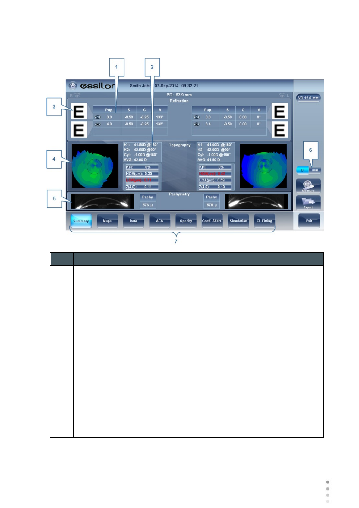
Overview of the Software
No
Description
1
Refraction
Displays the photopic and mesopic refractions, with the pupil sizes.
2
Keratometry
Displays the keratometry readings, KPI values (Keratconus Index), and High Order
and Low Order aberrations
3
E Simulation
The clarity of the E indicates how well the patient sees from the eye under
photopic or mesopic conditions. Double-tap (or double-click) the E to open a visual
acuity simulation for daytime / nighttime vision.
4
Topography
Displays the topographic map of the eye Double-tap (or double-click) to open the
topography map sub-tab for the eye.
5
Pachymetry
Displays a cross sectional view of the anterior chamber, as well as pachymetery
for the cornea
6
D/mm
Select button to toggle between Dioptres and mm
Summary Tab for Cataract/Corneal App Diagnostics:
Wave Analyzer Medica 700 User Guide
41
41
Page 48

No
Description
7
Subtabs
Select to see tab subject in greater detail
Summary tab for Glaucoma Evaluation diagnostic:
No
Description
1
Tonometry
Displays the IOP reading, average IOP, and corrected IOP (according to formula
chosen in settings)
2
Pachymetry
Displays the cross-sectional view of the corneal and pachymetery values
3
Subtabs
Select to view subject in greater detail.
Overview of the Software
Wave Analyzer Medica 700 User Guide
42
Page 49

Summary Screen for WF
No
Description
1
Refraction
Displays the photopic and mesopic refractions, with the pupil sizes.
2
E Simulation
The clarity of the E indicates how well the patient sees from the eye under
photopic or mesopic conditions. Double-tap (or double-click) the E to open a visual
acuity simulation for daytime / nighttime vision.
3
PSF
Displays the PSF, with no correction, and with LOA correction
4
Aberrations
Displays values for LOA and HOA under photopic and mesopic conditions
5
Subtabs
Select to view subject in greater detail
Overview of the Software
Wave Analyzer Medica 700 User Guide
43
43
Page 50

Summary Screen for Topo
No
Description
1
Keratometry
Displays the K1 and K2 values
2
Aberrations Chart
Displays the LOA and HOA as well as KPI (kerataconus index) values
3
Topo
Displays the corneal topography map
4
K Readings
Displays the keratometry values according to different pupil diameters (3,5,7mm)
5
Subtabs
Select to view subject in greater detail
Overview of the Software
Wave Analyzer Medica 700 User Guide
44
Page 51

Summary Screen for Pachymetry Diagnostic
No
Description
1
Pachy Image
Image of corneal anterior chamber with pachymetery results
2
Negative Pachy Image
A negative of the image of corneal anterior chamber with pachymetery results
3
Subtabs
Select to view subject in greater detail
Overview of the Software
Wave Analyzer Medica 700 User Guide
45
45
Page 52
Overview of the Software
No
Description
1
Refraction
Refraction is displayed in red:
When there is a difference of more than 2D in the refraction between the eyes,
or the cylinder difference between the eyes is more than 2D.
If the difference in refraction of the same eye in mesopic and photopic light is a
different of 1D sphere and 0.75D cylinder, the caution is also displayed.
When Sphere is above ± 20D or Cylinder is more than ± 8D.
When pupil diameter is less than 2.5mm in at least one eye.
When Pupil size difference between OD and OS is greater than 1mm.
When cylinder is greater than 4D in either eye.
2
Add
Add is displayed in red when the difference between the expected addition for age
and measured addition is great than 1D.
3
E Simulation
E simulation is outlined in red when:
The delta between the night and day sphere is >1D and/or cylinder is greater
than >0.75D
The Ocular HOA RMS equivalent sphere is larger than 0.5D in the right or left
eye.
Special Alerts
The summary tab will display alerts when results fall outside the expected range:
Wave Analyzer Medica 700 User Guide
46
Page 53

Overview of the Software
No
Description
4
RMS
RMS is displayed in red when corneal or RMS equivalent sphere is greater than
>4D
or when corneal HOA RMS equivalent sphere is greater than 0.5D in either eye.
5
KPI
KPI result is displayed in red when its value is higher than the normal population
6
IOPc
The IOPc value is displayed in red when the inter-ocular pressure is above
21mHg, irideo angles are displayed.
7
Pachymetry
Pachymetry is displayed in red and irideo anges are displayed when the central
corneal thickness is below 400µm or higher than the 700µm.
4. 5 Maps Tab
The Maps tab displays wavefront maps of aberrations and topographic maps of the cornea.
Ocular
Corneal
Internal
Compare
Ocular
The WF sub-tab displays wavefront maps of the measured ocular aberrations of one or both
eyes.
Display options allow you to view results for photopic and mesopic conditions, to view maps of
both eyes at once or of each eye individually, to isolate lower- and higher-order aberrations, to
change the step and central value of a map, and to superimpose guidelines of various types
onto the maps.
47
75
57
59
47
Aberrations values and maps can be shown in OPD (optical Path Difference) mode or in WFE
(WaveFront Error) mode, as defined in the settings screen (See the General subtab under
the results tab of the settings screen )
The Optical Path Difference (OPD) is defined as the difference between the aberrated and
the ideal unaberrated wavefronts. The OPD is positive if the aberrated wavefront leads the ideal
Wave Analyzer Medica 700 User Guide
152
47
Page 54

Overview of the Software
No
Description
1
Photopic /Mesopic selector
Select Day to display maps for daytime light conditions or Night to display maps for
nighttime light conditions.
2
Note
Select this to view an existing note, or add a note in the patient file. For more
information go to Adding a Patient .
3
Name and date
Patient's name and date and time of the measurement
unaberrated wavefront.
Also, if the aberrated wavefront curves in more than the unaberrated wavefront, the OPD is
positive. Therefore, a negative focal shift will introduce a positive aberration.
The WaveFront Error (WFE) is defined as the difference between the ideal unaberrated
wavefronts and the aberrated wavefronts. Essentially, WFE represents the required correction
for achieving unaberrated vision.
OPD and WFE modes relate in the following way:
OPD(x,y)= -WFE(x,y)
The chosen mode will be marked on each map in the lower right corner of the map.
89
Wave Analyzer Medica 700 User Guide
48
Page 55

Overview of the Software
4
History
Displays map results from previous and current topographic maps according to
selected date.
5
R or L mode
Displays single map, for the eye selected in the eye selector.
R or L mode
6
RR or LL mode
Display two maps, both for the same eye - namely, the eye selected in the eye
selector; displaying two maps of the same eye allows you to compare two types of
aberrations. For example, you could display HOA data in one of the maps, and LOA
data in the other.
RR or LL mode
7
RL mode
Displays two maps, one for each eye. Both maps are displayed with the same
display options.
RL mode
Wave Analyzer Medica 700 User Guide
49
49
Page 56

Overview of the Software
8
3D: Displays one map, for the eye selected in the eye selector, in 3D mode.
3D mode
Note: In 3D mode, you can change the orientation by dragging your finger (or the
cursor, if a mouse is connected to the unit) on the image.
9
Eye Indicator
Indicates and toggles between Left and Right eyes
10
Map-type selector
Select one of the following map types:
Total: Display composite of all aberrations
HOA: Display only high-level aberrations
LOA: Display only low-level aberrations
Sphere: Display only the sphere aberrations
Cylinder: Display only the cylinder aberrations
11
Date Tab
Opens a map from previous examinations. This is only available if the patient has
previous examinations saved in the database.
12
Zones: Select this button to superimpose zone guidelines (3, 5, and 7mm) on the
map display, or to remove them when they are displayed.
Map with Zones illustrated
Wave Analyzer Medica 700 User Guide
50
Page 57

Overview of the Software
13
Angles: Superimpose angle guidelines on the map display, or to remove them
when they are displayed.
Map with angle guidelines
.
14
Measure
Select to retake measurement. Warning, if selected prior to exiting and saving
measurement first time, your previous results will be erased.
15
Cross: Superimpose cross-hair guidelines on the map display, or to remove them
when they are displayed.
Map with cross-hair guidelines
16
Auto-scale: Activate or deactivate auto-scaling. When auto-scaling is activated, the
step and central value of the map are set automatically, and the Step and Central
Value selectors are disabled. When it is deactivated, the Step and Central Value
selectors are enabled.
17
Default button
Resets the Step and Central Value according to what is defined as default in the
Settings menu.
18
Central Value selector
Select the middle value for the color scale. Select to increase the value, or
to decrease it.
Changes you make to the Central Value are implemented when you select Apply.
19
Step selector
Select the rate of change for the color scale: the range of values represented by
each distinct color. Select to increase the step, or to decrease it.
Changes you make to the Step value are implemented when you select Apply.
Wave Analyzer Medica 700 User Guide
51
51
Page 58

Overview of the Software
20
Apply button
Implements changes you make to the Step and Central Values.
21
Map
Map of the aberrations.
22
Scale
Shows the color-coding scale used in the map.
No
Description
1
Note
Click to view an existing note, or add a note in the patient file. For more information
go to Adding a Patient .
2
Name and date
Patient's name and date and time of the measurement
Corneal
The Topo sub-tab displays topographic maps of the corneas of one or both eyes. Display
options allow you to view maps of both eyes at once or of each eye individually, to view four
different types of topographic maps, to change the step and central value of a map, and to
superimpose data and guidelines of various types onto the maps.
89
Wave Analyzer Medica 700 User Guide
52
Page 59

Overview of the Software
3
History
Displays map results from previous and current topographic maps according to
selected dates.
4
R or L: Displays one map, for the eye selected in the eye selector.
R or L mode
5
RR or LL:
Displays two maps, both for the same eye - namely, the eye selected in the eye
selector; displaying two maps of the same eye allows you to view the same data in
different ways. For example, you could display HOA data in one of the maps, and
LOA data in the other.
RR or LL mode
6
RL: Display two maps, one for each eye. Both maps are displayed with the same
display options.
RL mode
7
3D: Display one map, for the eye selected in the eye selector, in 3D mode.
3D mode
Note: In 3D mode, you can change the orientation by dragging your finger (or the
cursor, if a mouse is connected to the unit) on the image.
Wave Analyzer Medica 700 User Guide
53
53
Page 60

Overview of the Software
8
Values button
Shows or hides values on the maps
Values displayed on
map
9
Diopter/mm button
Toggles the display of values between diopters and millimeters.
10
Transparent
Displays the photo of the eye in the background with the projection of the Placido
rings
11
Map
Displays the topographic map of the cornea according to the map selected from
the drop down menu (in #5).
12
Rings
Displays the image of the Placido rings that were projected onto the cornea. Select
Rings to view ringer and make modifications.
Concentric rings
13
Kerato
Displays/hides the central keratometry values.
Wave Analyzer Medica 700 User Guide
54
Page 61

Overview of the Software
14
Pupil
Superpose a circular guideline on the map indicating where the pupil is or remove it
when it is displayed.
15
Zones
Superpose zone guidelines (3, 5, and 7mm) on the map display, or to remove them
when they are displayed.
Map with zone guidelines
16
Angles
Superimpose angle guidelines on the map display, or to remove them when they
are displayed.
Map with angle guidelines
Wave Analyzer Medica 700 User Guide
55
55
Page 62

Overview of the Software
17
Cross
Superpose cross-hair guidelines on the map display, or remove them when they
are displayed. Each gap is of 1mm in size.
Map with cross-hair
guidelines
18
Auto-scale
Activate or deactivate auto-scaling. When auto-scaling is activated, the step and
central value of the map are set automatically, and the Step and Central Value
selectors are disabled. When it is deactivated, the Step and Central Value
selectors are enabled.
19
Map-type selector
Select one of the following map types:
Axial: Display an axial topographic map
Instantaneous: Display a tangential topographic map
Elevation: Display an elevation topographic map
Refraction: Display a refractive topographic map
20
Date Tab
If more than one measurement was performed for the current patient, this tab
opens a drop-down menu with the dates of other measurements selected. To view
a map of a different date, select it from this menu.
21
Central Value selector
Select the middle value for the color scale. Select to increase the value, or
to decrease it.
Changes you make to the Step value are implemented when you select Apply.
22
Step selector
Select the rate of change for the color scale: the range of values represented by
each distinct color. Select to increase the step, or to decrease it.
Changes you make to the Step value are implemented when you select Apply.
23
Apply button
Apply changes you make to the Step and Central Value values.
24
Default button
Reset the Step and Central Value to their default values .
Wave Analyzer Medica 700 User Guide
157
56
Page 63

Overview of the Software
25
Scale
Indicates the color-coding scale used in the map.
26
Map
Details of the chosen map (topographic, aberrometry or refraction)
To display the values at a particular location of the map, click on a point in the map, and a table
with the value and location appears, as seen below.
Internal
The Internal aberrations map represents the calculated differences between the corneal
aberrations, and the ocular aberrations for each eye.
These aberrations can stem from anywhere along the optical system from posterior cornea to
retina; most commonly from the crystalline lens.
The maps can be displayed both in photopic and mesopic conditions.
57
Wave Analyzer Medica 700 User Guide
57
Page 64

Overview of the Software
No
Description
1
Left eye Indicator
Results displayed on this side of the screen are those of the left eye
2
Photopic /Mesopic selector
Select Day to display maps for daytime light conditions or Night to display maps
for nighttime light conditions.
3
Map Selection
Select a map from this menu to be displayed. The maps available for selection are:
Total, LOA, HOA, Cylinder, and Coma maps.
4
Eye selector
Select the eye you wish to be displayed.
5
Corneal map
This displays the corneal map that contains the corneal aberrations.
6
Internal map
This displays the internal map that contains the internal aberrations.
7
Total map
This displays the map that contains the total aberrations for the eye selected.
The Internal Maps are useful for indicating the location of the aberrations, for example in the
map below:
Wave Analyzer Medica 700 User Guide
58
Page 65

Overview of the Software
The Internal map here, illustrates how most of the total aberrations are due to Internal
aberrations. This could be an indication of Cataract, or an internal eye issue.
Compare
The Compare map feature compares two maps for the same patient and generates a delta map to
illustrate changes over time. This map is available after retreiving a patient's measurement when the
patient has more than one measurement in their file. Both corneal maps and ocular maps are available for
comparing.
Compare Corneal Maps
Wave Analyzer Medica 700 User Guide
59
59
Page 66

Overview of the Software
No
Description
1
Previous Date Tab
Select the date of the map that you would like to have the current map compared
to.
2
Current Date tab
By default, the date selected here will be for the current measurement. To select a
different date, click on the arrow, and a list of previous measurements will become
available for selection.
3
Map Selection
Select a map type from this menu to be displayed.
4
Map Selection
Select a map from this menu to be displayed. The maps available for selection for
Corneal maps are: Axial, Tangential, Total, LOA, and HOA maps.
5
Delta
To display data changes at any point on the map, click any location on the map and
the data will be displayed here.
No
Description
1
Current Date tab
By default, the date selected here will be for the current measurement. To select a
different date, click on the arrow, and a list of previous measurements will become
available for selection.
Compare Ocular Maps
Wave Analyzer Medica 700 User Guide
60
Page 67

Overview of the Software
No
Description
2
Previous Date Tab
Select the date of the map that you would like to have the current map compared
to.
3
Map Selection
Select a map type from this menu to be displayed, either Ocular or Corneal maps
are available for selection.
4
Map Selection
Select a map from this menu to be displayed. The maps available for selection for
Ocular maps are: Total, LOA, and HOA maps.
Corneal maps available for selection are: Axial, tangential, total, HOA, and LOA
maps,
5
Pupil Diameter
This is the maximum people diameter based on the pupil of the smaller map.
4. 6 Data Tab
The Data tab displays topographic information of the cornea.
Topo Data
Topo Data
The Topo Data sub-tab of the Data tab displays information about the shape of the cornea.
The sub-tab displays the results of the Topo test in three tables: Eccentricity, Sagittal, and
Meridians.
61
61
Wave Analyzer Medica 700 User Guide
61
Page 68

Overview of the Software
No
Description
1
Keratoconus Probability Index
Keratoconus probability results. See Keratoconus Table .
2
Sim_K
K1 & K2: Two orthogonal radii values where K1 is the flattest meridian and K2
is the steepest meridian
AVG: Average of K1 and K2 - the mean curvature value between K1 and K2
CYL: Corneal toricity - the difference in diopters between curvatures of the
principal meridians (K1 and K2) and axis of the negative cylind
3
Geometry table
Geometry of the cornea ( P=1-e2) and (Q= P-1):
P: Is a factor indicating how similar the shape of the cornea is to a perfect
sphere, in the case of a perfect sphere, P=1
e: This is a factor describing the eccentricity of the cornea,for a perfect sphere,
e=0.
Q: Is a factor indicating the asphericity of the cornea, for a sphere, Q=0
Note: An example of average corneal values: P=0.8, Q=-0.2, and e=0.45. These
are not the values of a perfect sphere as average corneas are aspheric.
4
Menu
Select the geometrical data to be displayed: Eccentricity , Sagittal Radius
and Meridians.
5
Eccentricity Table
Displays the local eccentricity values according by location on the cornea.
63
Wave Analyzer Medica 700 User Guide
64 64
62
Page 69

Overview of the Software
p8 mm
e8 mm
e
2
8mm
Q 8 mm
p
4.5 mm
e
4.5 mm
e
2
4.5 mm
Q 4 .5 mm
Mean
0.72
0.51
0.28
-0.28
0.86
0.31
0.14
-0.14
Std.
Dev
0.13
0.14
0.13
0.13
0.12
0.24
0.12
0.12
Min
0.14
-0.22
-0.05
-0.86
0.47
-0.46
-0.21
-0.53
Max
1.05
0.93
0.86
0.05
1.21
0.73
0.53
0.21
*Formulas:
We use the following formula when P<1: ( P=1-e2) and (Q= P-1).
*Data taken from : "The Optical Quality of the Cornea", by Calossi A. (Fabiano Editore)
Italy; 2002:1-13.
Here is data taken from study sample of 1030 eyes. It includes the mean values, standard deviation, and
range of apshericity. The data is relative to the anterior surface of the cornea on a diameter of 8mm and an
optic zone of 4.5mm
Keratoconus Table
The Keratoconus table displays the following data:
KPI: Index of the probability of keratoconus
CAUTION: Keratoconus indices are designed to be an adjunct to a clinical
examination, and should never be used as a sole assessment tool in the diagnosis
of Keratoconus.
Results of a clinical trial of the Keratoconus Prediction Index (KPI) are described in
reference 1 and more details of the mathematics are given in reference 2.
Reference 1. Calossi A. Le altimetrie corneali con sistemi a disco di Placido. In: Mularoni A, Tassinari G,
eds. La Topografia Altitudinale. Canelli, Italy: Fabiano Editore; 2005:136-139.
Reference 2. Maeda N, Klyce SD, Smolek MK, Thompson HW. Automated keratoconus
SI: Symmetry index - the difference between the mean power of two circular zones
centered in the vertical axis
63
AGC: Apical Gradient of Curvature - the mean variation per unit of length of the corneal
power between the corneal apex and the periphery of the keratoconus
AK: Apical Keratometry - the curvature of the corneal apex
Note: Values that are associated with a high probability of keratoconus are marked with an
asterisk, like the SI and AGC values in this example:
Wave Analyzer Medica 700 User Guide
63
Page 70

Overview of the Software
Eccentricity Table
The Eccentricity table shows the eccentricity of the cornea (P, e, or q as selected in the
settings menu) at various predefined positions. The positions are defined by the meridian and
by the angle from the keratometric measurement axis. R0 is the apical position (corneal apex)
and the angles are 10º, 15º, 20º, 25 º, and 30º. The meridians used are the nasal, temporal,
inferior, and superior semi-meridians and the horizontal and vertical meridians. The mean is
the average of the horizontal and vertical meridians.
Sagittal Radius Table
The Sagittal Radius table shows the radius of the curvature of the cornea at various
predefined positions. The positions are defined by the meridian and by the angle from the
keratometric measurement axis. R0 is the apical position (corneal apex) and the angles are
10º, 15º, 20º, 25 º, and 30º. The meridians used are the nasal, temporal, inferior, and superior
semi-meridians and the horizontal and vertical meridians. The mean is the average of the
horizontal and vertical meridians.
Wave Analyzer Medica 700 User Guide
64
Page 71

Overview of the Software
Sagittal Radius table
No
Column
1
Measurement
Notation of measurement number and average
Tonometry Tab
The Tono tab displays the results of tonometry measures, and the results of pachymetry
measures. For each eye, the results of the measures are displayed individually, and their
average is also displayed, in the following columns:
65
Wave Analyzer Medica 700 User Guide
65
Page 72

Overview of the Software
No
Column
2
IPO mm/Hg
Displays the actual intraocular pressure that was measured.
3
Pachy
Displays the thickness of the cornea at its center, in microns.
4
IPOc mm/Hg
Displays corrected values for the intraocular pressure, taking the pachymeter
readings into account.
5
ACD
Displays the anterior chamber depth
6
ACV
Displays the anterior chamber volume.
7
Kappa Angle
Displays the kappa angle.
8
Decentration
Displays the decentration between the pupil apex and the visual point on the cornea.
9
IC Angles
Displays the interior chamber angles for each eye.
Warning: The safety and efficacy of the Wave Analyzer Medica 700 in measuring
intraocular pressures in patients with greater than 3 diopters of corneal astigmatism or
greater than 33mmHg of intraocular pressure has not been evaluated.”
4. 7 ACA
This tab includes data on the Anterior Chamber of the Cornea
Anterior Chamber Analysis
The Anterior Chamber Analyses sub-tab of the Cornea tab displays diagram and graph for
the anterior chamber analysis (pachymetry, irido corneal angle, corneal thickness). The user
can edit this diagram by re-positioning the measured points. Note: it is only possible to save
the reposition of the points immediately after the measurements. When retrieving results,
points that are repositioned will not be saved.
Wave Analyzer Medica 700 User Guide
66
Page 73

Overview of the Software
No
Description
1
Edit
Displays the Edit screen. In this screen, the measured points can be repositioned
by the user. For more information, see Edit .
2
Negative
Displays a negative of the image of the cornea.
3
Enhance
Enhances the outlines of the image.
4
Corneal Thickness
Displays values of the corneal thickness in a few areas on the cornea image.
5
Irido Angles
Displays the Irido Angles values and positions on the image (11)
6
ACD
Displays the Anterior Chamber Depth in millimeters (10)
7
WTW
Displays the White to White (in relation to the cornea) distance.
8
Kappa Angle
68
67
Wave Analyzer Medica 700 User Guide
67
Page 74

Overview of the Software
Displays the angle between the visual axis and the pupillary axis
9
Cornea
Scheimpflug image of the cornea. T Indicates that this is the temporal side of the
eye. N Indicates that this is the nasal side of the eye. The Orientation Indicates
the orientation of the pachymetry (in the example, a horizontal cut).
The Anterior Face of the Cornea is marked in red while the Posterior Face of
the Cornea is marked in green.
The Central Corneal Thickness (CCT), in microns is displayed in red.
Edit
The Edit screen allows the user to relocate the measured points on the image in order to
obtain better values. Clicking on one of the three sections of the image will display a zoom-in of
that image. It is then possible to drag each point to a new location.
Please note: if the measured results are not within the following bounds, the Edit screen will be
automatically displayed when entering the Anterior Chamber Analysis results for that eye
5° < Irido Angle < 60°
1.5mm < ACD < 4.5mm
8mm < WTW
Irido points should be within their respective EDIT window
-30° < Pupil Angle < +30°
Wave Analyzer Medica 700 User Guide
68
Page 75

Overview of the Software
200µ < Corneal Thickness < 800µ
Corneal thickness values should be symmetrical respective to center
Edit Central Corneal Thickness
To edit central corneal thickness:
Select the yellow cross and drag it to the outer border of the cornea.
Please note: This is only recommended if dissatisfied with the automatic corneal thickness recognition.
This will change the values for central corneal thickness and display only the CCT, the other values along
the periphery of the cornea will be erased.
Wave Analyzer Medica 700 User Guide
69
69
Page 76

Overview of the Software
No
Description
1
Ocular aberrations
Displays values for ocular high order aberrations
2
Corneal aberrations
Displays values for corneal high order aberrations
3
Lens
Displays the retro illumination image of the lens and opacities
4
LOCS
This subtab contains a menu of retro illumination images. After entering this
subtab, select the image that most clearly resembles your patient's retro image .
More details listed below.
4. 8 Opacity Tab
The Opacity tab graphically displays the results of several measures - ocular aberrations,
corneal aberrations, retro-illumination, and pachymetry and Shack-Hartmann - to give a general
overview of the anterior chamber.
Wave Analyzer Medica 700 User Guide
70
Page 77

No
Description
5
Cross Section
Cross sectional image of the cornea and interior chamber
6
Shack-Hartmann
Shack-Hartmann image.
Note: To view a larger version of an image, double-click it.
No
Description
1
Posterior
Select the image that most clearly resembles the patient's retroillumination
image.The image on top represents the mildest posterior opacity, while the image
on bottom represents the most severe posterior opacity.
2
Cortical
Select the image that most clearly resembles the patient's retroillumination image.
The image on top represents the mildest cortical opacity, while the image on
bottom represents the most severe cortical opacity.
3
Opalescence
Select the image that most clearly resembles the patient's retroillumination image.
#1 represents the least opacity, #5 represents the most opacity.
LOCS Screen
Once this subtab is selected, the following screen appears:
Overview of the Software
Wave Analyzer Medica 700 User Guide
71
71
Page 78

Overview of the Software
No
Description
4
Color
Select the image that most clearly resembles the patient's retroillumination image.
#1 represents the lightest color, #5 represents the darkest color.
Select the image that best matches the cornea of the patient. There are 4 categories to choose
from: Posterior, Cortical, Opalescence, and Color.
Please note: Several options can be selected at once in the LOCS menu.
After exiting the results screen, you will see the message:
Click Yes to save or No to discard changes.
4. 9 Coeff. Aberr.
The Aberration Coefficients tab shows the values of the Zernike coefficients in units of mm
for:
Ocular
Corneal
Internal
There are three options for the aberration coefficients to be displayed:
74
75
76
Main Values: Shows a selection of the most common aberrations; defocus, astigmatism, total
lower order (LOA), total higher order (HOA), coma, spherical aberration, fourth order
astigmatism, trefoil and tetrafoil. Aberrations are shown in value and axis form.
Wave Analyzer Medica 700 User Guide
72
Page 79

Overview of the Software
LOA: Shows the values of the lower order aberrations, total LOA, tilt, defocus and astigmatism.
HOA: Shows the values of the common higher order aberrations, total HOA, trefoil, coma,
tetrafoil, fourth order astigmatism, spherical aberration, pentafoil, fifth order trefoil and fifth order
coma.
Aberrations values and maps can be shown in OPD (optical Path Difference) mode or in WFE
(WaveFront Error) mode, as defined in the settings screen (See the General subtab under the
results tab of the settings screen )
The Optical Path Difference (OPD) is defined as the difference between the aberrated and
the ideal unaberrated wavefronts. The OPD is positive if the aberrated wavefront leads the ideal
unaberrated wavefront.
Also, if the aberrated wavefront curves in more than the unaberrated wavefront, the OPD is
positive. Therefore, a negative focal shift will introduce a positive aberration.
The WaveFront Error (WFE) is defined as the difference between the ideal unaberrated
wavefronts and the aberrated wavefronts. Essentially, WFE represents the required correction
for achieving unaberrated vision.
OPD and WFE modes relate in the following way:
OPD(x,y)= -WFE(x,y)
The chosen mode is marked on the left side of the coefficient chart above the table.
73
Wave Analyzer Medica 700 User Guide
73
Page 80

Overview of the Software
No
Description
1
Aberration coefficients
Choose aberration coefficients to be displayed
2
Left / Right display
Choose right / left display
3
Photopic / Mesopic display
Choose day / night display
4
Graphical representation
Each of the bars represents either Night/Day aberrations, or Right/Left aberrations,
depending on what is selected in 2 & 3.
5
Convention
This displays the Zernike convention, either WFE or OPD according to what was
selected in the settings menu.
6
Numerical representation
These are the values for the coefficient of aberrations, they are listed by type and
according to either Night/Day or R/L eyes.
Ocular
The Ocular sub tab shows the value of the Zernike coefficients of the entire eye from the
wavefront measurement. It is possible to display either day / night data or right / left data.
Wave Analyzer Medica 700 User Guide
74
Page 81

Overview of the Software
No
Description
7
Scale
Changes scale of graphical representation
No
Description
1
Aberration coefficients
Choose aberration coefficients to be displayed
2
Left / Right display
Choose right / left display
3
Photopic / Mesopic display
Choose day / night display
4
Graphical representation
Each of the bars represents either Night/Day aberrations, or Right/Left aberrations,
depending on what is selected in 2 & 3.
Corneal
The Corneal sub-tab shows the values of the Zernike coefficients from the front corneal
surface from the corneal topography measurement. It is possible to display either day / night
data or right / left data.
Wave Analyzer Medica 700 User Guide
75
75
Page 82

Overview of the Software
No
Description
5
Convention
This displays the Zernike convention, either WFE or OPD according to what was
selected in the settings menu.
6
Numerical representation
These are the values for the coefficient of aberrations, they are listed by type and
according to either Night/Day or R/L eyes.
7
Scale
Changes scale of graphical representation
No
Description
1
Aberration coefficients
Choose aberration coefficients to be displayed
2
Left / Right display
Choose right / left display
Internal
The Internal Coefficient of Aberrations tab represents the differences between the corneal
aberrations, and the ocular aberrations for each eye. Zerniki coefficients are displayed for
Corneal, Internal and total aberrations. For example, the graph below illustrates that most of the
HOA, Defocus, and RMS are due to Internal eye aberrations.
Wave Analyzer Medica 700 User Guide
76
Page 83

Overview of the Software
No
Description
3
Photopic / Mesopic display
Choose day / night display
4
Graphical representation
Each of the bars represents either Night/Day aberrations, or Right/Left aberrations,
depending on what is selected in 2 & 3.
5
Convention
This displays the Zernike convention, either WFE or OPD according to what was
selected in the settings menu.
6
Numerical representation
These are the values for the coefficient of aberrations, they are listed by type and
according to either Night/Day or R/L eyes.
7
Scale
Changes scale of graphical representation
4. 10 Simulation
Visual acuity measures the eye's ability to distinguish object details and shape using HOA
(High Order Aberrations) and LOA (Low Order Aberrations).
Visual Acuity measurement is applicable to Topography (corneal) and to Wave Front
(ocular). Results for both options are interpreted in the same manner.
Simulations are available are:
Ocular
Corneal
QV Tab
78
79
81
77
Wave Analyzer Medica 700 User Guide
77
Page 84

Ocular
No
Description
1
Photopic selector
Choose day display
2
Mesopic
Choose night display
3
VA selector/PSF
Allows you to toggle between the Visual acuity card display and the PSF (Point
Spread Function) Display
4
MTF selector
Displays the MTF graph.
5
Correction selector
Select HOA to access the same image with an HOA correction. Select LOA to
access the same image with a LOA correction. It is possible to select no correction
at all, or Full correction.
6
R/L
Display two cards, one for each eye. Both cards are displayed with the same
display options
Overview of the Software
Wave Analyzer Medica 700 User Guide
78
Page 85

Overview of the Software
No
Description
7
HOA/LOA
Displays two cards for each eye, one with HOA and one with LOA corrections.
8
Day Night
Display correction for day or night conditions for one eye.
9
Visual Acquity image
Reflects the actual quality of patient eyesight.
10
PSF
Image of the corneal PSF (Point Spread Function).
No
Description
1
Photopic selector
Choose day display
2
Mesopic
Choose night display
Corneal
The Corneal sub-tab is identical to the Ocular one, since the Visual Acuity measurement is
applicable to Topography and to Wave Front. Results for both options are interpreted in the
same manner.
Wave Analyzer Medica 700 User Guide
79
79
Page 86

Overview of the Software
No
Description
3
VA selector/PSF
Allows you to toggle between the Visual acuity card display and the PSF Display
4
MTF selector
Displays the MTF graph.
5
Correction selector
Select HOA to access the same image with an HOA correction. Select LOA to
access the same image with a LOA correction. It is possible to select no correction
at all, or Full correction.
6
RL
Display two cards, one for each eye. Both cards are displayed with the same
display options
7
HOA LOA
Displays two cards for each eye, one with HOA and one with LOA corrections.
8
Day Night
Display correction for day or night conditions for one eye.
9
Visual Acuity image
Reflects the actual quality of patient's eyesight.
10
PSF
Image of the corneal PSF (Point Spread Function)
Wave Analyzer Medica 700 User Guide
80
Page 87

Overview of the Software
No
Description
1
Pupil Selector
Select to display data for either mesopic or photopic pupils.
2
RL
Display two cards, one for each eye. Both cards are displayed with the same
display options
3
History
Displays map results from previous and current topographic maps according to
selected date
4
Photopic /Mesopic selector
Select Day to display maps for daytime light conditions or Night to display maps
for nighttime light conditions.
5
100%
This line displays the MTF function with no aberrations present.
6
LOA corrections
The yellow line displays the MTF with all the LOA aberrations corrected, only HOA
aberrations are present.
QV
The QV (Quality of Vision) tab opens MTF (Modulation Transfer Function), displaying the LOA correction,
displaying without any corrections, and displaying the 100% corrections function.
Wave Analyzer Medica 700 User Guide
81
81
Page 88

Overview of the Software
No
Description
7
No Correction
This displays the MTF with no corrections, both HOA and LOA aberrations are
present.
4. 11 CL Fitting
In this tab you can fit contact lens to a patient according to the test results.There are several
contact lens types listed according to their manufacturer as well as their dimensions in the
dropdown menu of the CL Fitting tab. Choose a specific lens type and the software calculates
the approximate fitting for you.
Note: It is possible that the contact lens dimensions listed in the software have
changed since this version was updated. To avoid miscalculations, we recommend
checking all the dimensions directly from contact lens manufacturer before prescribing
contact lenses.
82
Lens
Values
Display
Actions
84
85
86
Lens
Choose a lens manufacturer and then select the most suitable lens from the given selection.
Wave Analyzer Medica 700 User Guide
82
Page 89

Overview of the Software
No
Description
1
TLT (Tear Layer Thickness)
Permits setting the value by which the lens is lifted at its center with respect to the
cornea.
When the TLT is modified, a new model lens or a new manufacturer must
be selected; the lenses that meet the new application criteria are displayed.
The program “remembers” the variation in TLT setting and uses this criterion the
next time the Contact Lenses environment is accessed.
2
Fix Angle
The orientation of K1, allows selecting the direction of the flattest meridian of a toric
lens. The default value is the direction of the flattest meridian of Sim K. You can
modify this parameter to simulate a lens rotation. This parameter need to be set
before you choose the manufacturer.
3
Manufacturer
Select a contact lens manufacturer
4
Design
Select the most suitable lens from the given selection.
5
Diameter
Choose the diameter of the lens
6
Base Curve
Choose the base curve of the lens
x
83
Wave Analyzer Medica 700 User Guide
83
Page 90

No
Description
7
Display
Displays the contact lens image superimposed on the image of the eye
8
Scale
The scale used for the image in the display
Values
No
Description
1
Section Display
Displays a cross-section of the lens
2
Values Display
Select the display of the values on the contact lens map
3
Values Table
Displays the values of the point where the user clicks on the image
4
Refraction values
Displays the refraction values for the patient
Overview of the Software
Wave Analyzer Medica 700 User Guide
84
Page 91

No
Description
5
Keratometry values
Displays the keratometry values of the patient
6
Display
Displays the contact lens image superimposed on the image of the eye
7
Scale
The scale used for the image in the display
Display
No
Description
1
1st Scale selection
2
2nd Scale selection
3
3rd Scale selection
4
Pupil
Displays the pupil on the map
5
Kerato
Displays kerato values and cross on the map
Overview of the Software
Wave Analyzer Medica 700 User Guide
85
85
Page 92

6
Angles
Displays angles on the map
7
Refraction values
Displays the refraction values for the patient
8
Keratometry values
Displays the keratometry values of the patient
9
Display
Displays the contact lens image superimposed on the image of the eye
10
Scale
The scale used for the image in the display
Actions
No
Description
1
Move lens
Moves the lens on the image of the eye
2
Tilt lens
Tilts the lens
3
Reset move lens
Undos all changes
Overview of the Software
Wave Analyzer Medica 700 User Guide
86
Page 93

Overview of the Software
No
Description
4
Refraction values
Displays the refraction values for the patient
5
Keratometry values
Displays the keratometry values of the patient
6
Display
Displays the contact lens image superimposed on the image of the eye
7
Scale
The scale used for the image in the display
Wave Analyzer Medica 700 User Guide
87
87
Page 94

5. Managing Patients
V
Page 95

Managing Patients
You can manage the patient database - add patients, modify patient information, search for
patients, and delete patient records - in the Patient screen .
Adding a New Patient
89
Adding a New Patient Before Performing an Exam
Adding a Person from the Same Family
Modifying a Patient's Information
Selecting Patients
Searching for a Patient
Deleting Patients
94
95
96
93
91
21
89
5. 1 Adding New Patients
You can add a new patient to the database either before or after you perform exams on them.
You can also add a number of related patients to the database quickly by duplicating the current
patient record and modifying those parts that are different.
Adding a Patient Before Performing an Exam
Adding a Patient After Performing an Exam
Adding a Person from the Same Family
Adding a Patient from the Waiting Room
89
91
91
92
Adding a Patient Before Performing an Exam
To add a new patient before performing an exam:
In the Home screen , select the Add Patient option
- OR -
In the Patient screen , select the Add Patient button.
20
21
89
The Patient Information dialog box is displayed on top of the Patient screen .
21
Wave Analyzer Medica 700 User Guide
89
Page 96

Managing Patients
Add Patient dialog box on top of the Patient screen
No
Description
1
Note
Select to add a Note in the patient file. This note can be accessed by clicking on
symbol in the results screen, in the measurement screen, or in the patient
screen. Once information has been added, the note will appear like this .
2
Cancel
Cancels saving new patient.
3
Save
Save the new patient in the database, close the dialog box, and display the patient
screen.
4
Save & New
Save the new patient in the database and leave the dialog box open. You can add
an additional patient by modifying the fields as necessary and saving the additional
patient's information.
Note: This is convenient if you want to create a number of new patient records at
one time. For example, you could use this option to create new patient records for
all of the members of a family.
Fill in the fields.
Select one of the following:
Wave Analyzer Medica 700 User Guide
90
Page 97

Managing Patients
No
Description
5
Save and Diag
Save the new patient in the database, close the Patient screen , and open the
Measure screen . This enables you to go directly from adding a new patient in
the database to performing measurements on them.
21
24
Adding a Patient After Performing an Exam
You can perform an exam without first providing patient information. When the exam is
completed, the exam results are saved in the database as temporary records under
automatically generated names - with "Temp" as the surname, and a number as the first
name. Temporary records remain in the database until you delete them manually or they are
deleted by the system during routine maintenance. At any time before they are deleted, you can
convert them into permanent patient records by adding patient information to them, or by
cutting the results from the temporary patient record and pasting them into a permanent record
(see Moving Test Results to a Different Patient ).
128
Adding Related Patients
To add patients from the same family to the database:
In the Patient Information dialog box, fill in the fields for the first member of the family.
Select Save & New. The patient is saved in the database, but their information is still
displayed in the dialog box.
Modify the information in the dialog box. Select Save & New if you want to add additional
family members to the database, or either Save or Save and Diag if there are no
additional family members to add. For additional information about these options, see
Adding a Patient Before Performing an Exam .
89
89
Adding a Patient from an XML database
The Wave Analyzer Medica 700 is XML enabled, allowing data import from compatible XML
databases. To import the data to the device, click on the icon located at the top left of
the Measurement screen. Once you have imported the data, continue with the measurement.
The measurement will be saved with the name and details from the database.
If the icon is grayed out it means that there is no data available for importing. Before
beginning to import data, please make sure that your settings are configured properly in the
Export Data Configuration .
161
Wave Analyzer Medica 700 User Guide
91
91
Page 98

Managing Patients
No
Description
1
XML Import
Make sure that this checkbox is selected.
2
Path
Click on this field to open a browser and select the path to import the XML data .
3
Clear After Import
This button will erase all of the data in the Waiting Room popup once it has been
imported.
This erases the data found on the path the user selects and once it is erased it
cannot be reaccessed.
4
Save
Click Save to implement these changes.
Adding a Patient from the Waiting Room
The Waiting Room feature allows you to import patients from an external XML database. First
you must make sure to have the following configurations in the Settings menu:
No Descripti
Note: Only Patients' names and birthdates are imported from the XML database.
Existing data will not be modified Once the settings menu is defined, provided that
there is data in the external XML database,
Wave Analyzer Medica 700 User Guide
92
Page 99

Managing Patients
No
Description
1
Patient Checkboxes
Select the checkboxes of the Patient/s you wish to Import.
2
Add Patient
Click on the Add Patient button to import the patient/s. Now, the patients will
appear along with the rest of the patients in the patients screen.
the button becomes selectable. Click on the button and the following
popup appears:
No Description
5. 2 Modifying a Patient's Information
To modify a patient's information:
In the Patient screen , in the patient list, select the patient.
Below the patient list, select Modify Patient. The Patient Information dialog box opens.
Modify the fields as necessary.
21
93
Select Save. The changes are saved, and the dialog box closes.
Wave Analyzer Medica 700 User Guide
93
Page 100

Managing Patients
Patients selected individually and as a group
No
Description
1
Check box selected (to select patients as a group)
2
Patient selected (as an individual)
5. 3 Selecting Patients
There are two ways patients can be selected: individually, or as part of a group. Patients must
be selected individually in order to see or modify their personal information and to view and
manage their test results. Patients can be selected as a group in order to delete their records
from the database.
To select a single patient in order to see the patient's information and
test results:
In the Patient screen , in the patient list, select the patient. The patient's entry in the list
is highlighted with a blue border.
To select one or more patients in order to delete them:
In the Patient screen , in the patient list, select the check box beside each patient you
want to delete.
21
21
Please note, only patients with their checkboxes selected will be deleted.
Wave Analyzer Medica 700 User Guide
94
 Loading...