

Page 1
User Manual
Page 2

Page 3

USER MANUAL > CONTENTS
CONTENTS
I. INTRODUCTION 7
II. FIRST STEPS WITH DELTA 2 11
1. Descriptive diagrams 13
2. Instructions for use 15
a. Turn on the product 15
b. Turn off the product 15
c. Using the touch screen and keypads 15
d. Work screens 17
III. CARRY OUT AN OPTICAL TRACING 19
1. The tracing environment 21
a. Menu screen 21
b. Jobs and working modes 22
2. Shape management and storage 24
a. Menu screen 24
b. Job list 25
c. Creating a job 26
d. Working in current job mode (job A) 27
3. Optical tracing 27
4. Enter the curve and frame base 31
5. Case of a mechanical tracing 32
a. Connection with a PHI tracer 32
b. Connection with a Tess tracer 33
IV. CENTER AND BLOCK A LENS 35
1. Centering environment 37
a. Description of the centering blocking system 37
b. Menu screen 41
c. Calling up a shape 43
2. Centering a lens for a high-base frame 44
3. Centering a single vision lens 44
4. Centering a progressive lens 46
a. Centering a progressive lens using re-marked micro-engravings 47
b. Centering a lens using manufacturer markings 48
5. Centering bifocal / trifocal lenses 50
6. Centering an executive lens 51
7. Centering a mid-distance lens 53
a. Centering a lens using re-marked micro-engravings 54
b. Centering a lens using manufacturer markings 55
8. Blocking a lens 57
a. Prepare blocking 57
b. Blocking 59
V. MODIFYING THE LENS SHAPE 63
1. Menu screen 65
2. Modifying a shape 66
a. Enlarging, reducing or rotating a shape 66
b. Free-form modification 68
Page 4

USER MANUAL > CONTENTS
c. Retouching a shape 69
3. Archiving/saving a shape 70
VI. PREPARING A DRILLED JOB 71
1. Menu screen 73
2. Configuring a drilling point 75
a. Creating a drilling point 75
b. Delete one drilling point 75
c. Dimensioning a drilling point 76
d. Adjusting the position of a drilling point 77
3. Drilling models 79
a. Importing a model 79
b. Saving a model 80
VII. EDGING A LENS 81
1. Edger working environment 83
a. Menu screen 83
b. Calling up a shape 85
c. Lens set-up and feeling 85
2. Perform a Beveling 86
a. Automatic beveling 87
b. Legend screen for customized bevels 87
c. Customized beveling 88
d. Modifying the bevel curve 89
e. Modifying the bevel curve at a particular point 90
f. Displacing the bevel curve 91
3. Grooving 91
a. Automatic grooving 92
b. Customized groove legend screen 93
c. Customized grooving 94
d. Modifying the groove curve 95
e. Modifying a point in the groove curve 96
f. Displacement of the groove curve 96
4. Flat-edge finishing 97
5. Perform a drilling job 97
a. Automatic drilling 98
b. Legend screen for customized drilling 99
c. Customized drilling 101
6. Polishing 102
7. Chamfering 102
8. Perform a Retouching 103
VIII. SET THE EDGING SYSTEM 105
1. Configure the tracer-centerer-blocker and the edger 107
a. Time, date and language 107
b. Screensaver 108
c. Connections 109
2. Customize the tracer and the centering device 110
a. Working modes and display precision 110
b. Decentration mode 111
c. Action bar 112
d. Brightness 113
3. Adjusting the precision of the edger 114
a. Adjusting the diameter of the finished lenses 114
b. Adjusting the position of the bevel and groove 115
Page 5

USER MANUAL > CONTENTS
c. Adjusting the diameter of drill-holes 115
d. Adjusting the chamfer 116
e. Adjusting the groove 117
4. Restoring the factory settings 117
IX. MAINTENANCE & SERVICING 119
1. Perform the autotest of the tracer 121
2. Performing the edger autotest 123
3. Checking and calibrating the tracer 124
a. Calibrating the touch screen 124
b. Control and calibrate the centering device 125
c. Control and calibrate the blocker 126
d. Check the optical system 127
4. Testing and calibrating the edger 128
a. Control the calibration of the monofeeler 128
b. Calibrating the touch screen 129
5. Statistics and technical history of the tracer 129
a. Tracer-centerer-blocker statistics 129
b. Technical history and errors 132
6. Statistics and technical history of the edger 133
a. Edger cycles 133
b. Technical history and errors 134
7. Make a backup of the jobs and display configuration 135
8. Changing or cleaning the blocking tube 137
9. Changing or cleaning the edger tools 139
a. Changing or cleaning the drill bit 139
b. Changing the grooving or chamfering wheel 140
10. Maintain and clean the tracer-centerer-blocker 142
a. Precautions required 142
b. Clean the reflectors and the lens 142
c. Clean the tube 142
11. Maintaining and cleaning the edger 142
a. Precautions required 142
b. Clean the GCD module 143
c. Dismantle and clean the door 143
d. Dress the wheels 144
TECHNICAL DATA 147
1. Environment 148
2. General features 148
3. “Tracer centering device blocker” Function 148
4. “Edger” function 149
GENERAL INFORMATION 151
1. Symbols 152
2. Modifications 152
3. Declaration of conformity 152
4. Copyright 152
5. Materials and products 152
6. Safety instructions: 153
7. Electromagnetic waves 153
GLOSSARY 155
Page 6

USER MANUAL > CONTENTS
Page 7

I. INTRODUCTION
Page 8

USER MANUAL > INTRODUCTION
8 Delta 2 - Edging system > v2 - 08.16
Page 9

USER MANUAL > INTRODUCTION
The screens and features vary according to the product used:
Delta 2 Classic
Delta 2
Delta 2 Drill
Correction of the procedure of optical tracing.
Addition of the procedure for changing the blocking tube.
Addition of the maintenance chapter concerning the edger.
This handbook documents the use of the Delta 2 Drill edger.
You have memory version: V1.2.0.
Delta 2 - Edging system > v2 - 08.16 9
Page 10

USER MANUAL > INTRODUCTION
10 Delta 2 - Edging system > v2 - 08.16
Page 11

II. FIRST STEPS WITH DELTA 2
Page 12

USER MANUAL > FIRST STEPS WITH DELTA 2
12 Delta 2 - Edging system > v2 - 08.16
Page 13
1.
2.
3.
4.
5.
6.
7.
1.
2.
3.
4.
This chapter contains all the information relating to the product’s first use.
Product description (p.13)
Using the device (p.15)
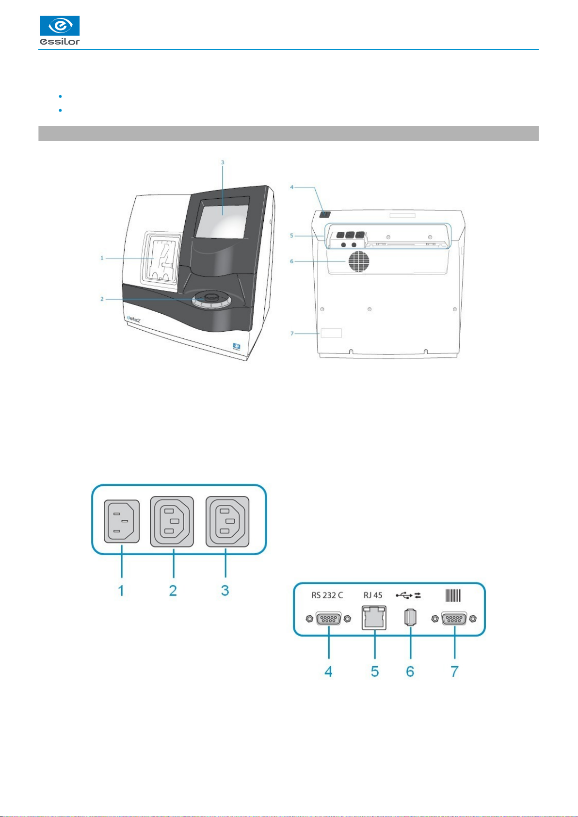
1. Descriptive diagrams
Trough
Centering blocking environment
Screen
Main switch
Connectors
Fan
Manufacturer plate
Power socket
Solenoid valve socket
Pump socket (tank + pump) / Solenoid valve socket (town)
Serial port
USER MANUAL > FIRST STEPS WITH DELTA 2
Delta 2 - Edging system > v2 - 08.16 13
Page 14

5.
6.
7.
Ethernet port
USB port
Barcode reader port
Accessories
Transport wedges to be kept
Use accessories
Reflector
Tube small diameter Ø 42 mm
Tube large diameter Ø 53 mm
Calibration table
22 mm posiblock holder
18 x 14 mm posiblock holder
22 mm stop
18 x 14 mm stop
Unblocking clamp
Ø 1.0 mm drill bit (mounted on the module) (option)
Ø 0.8 mm drill bit (option)
Ø 25 mm grooving wheel (mounted on the module)
Chamfering wheel (mounted on the module)
White felt tip marker
Servicing accessories
Orange dressing stone for glass roughing wheel
White dressing stone for finishing wheel
Square dressing stone for polishing wheel
Open-ended spanners for tool changeover (quantity 2)
Options
Trimaterial edger for chamfering glass lenses
Barcode reader
Roll of barcode labels
Open or closed circuit spraying kit
Connection accessories
Power cable
RJ45 cable for the tracer-edger connection
Wastewater evacuation pipe with attachment ring
USER MANUAL > FIRST STEPS WITH DELTA 2
14 Delta 2 - Edging system > v2 - 08.16
Page 15
3
2
1
3
2
1
1.
2.
2. Instructions for use
In this section, you will find all the information concerning the following:
The turning on (p.15) and of the productoff (p.15)
The use of the touch screen and the keyboards (p.15),
The description of the main work screen (p.17).
a. Turn on the product
Press on the main switch located on the top of the product to power it up.
Then, the edger part is initialised.
On the screen, press on the icon to finish the initialisation phase.
b. Turn off the product
Before switching off the edger:
check that there is no lens in the trough
check that the lens clamp shafts are loosened and that the trough door is open
go at the work screen.
Press on or , then on .
Select to confirm.
Extended period of non-use
For a prolonged period of non-use (a few days), it is preferable to power down the product using the main switch.
c. Using the touch screen and keypads
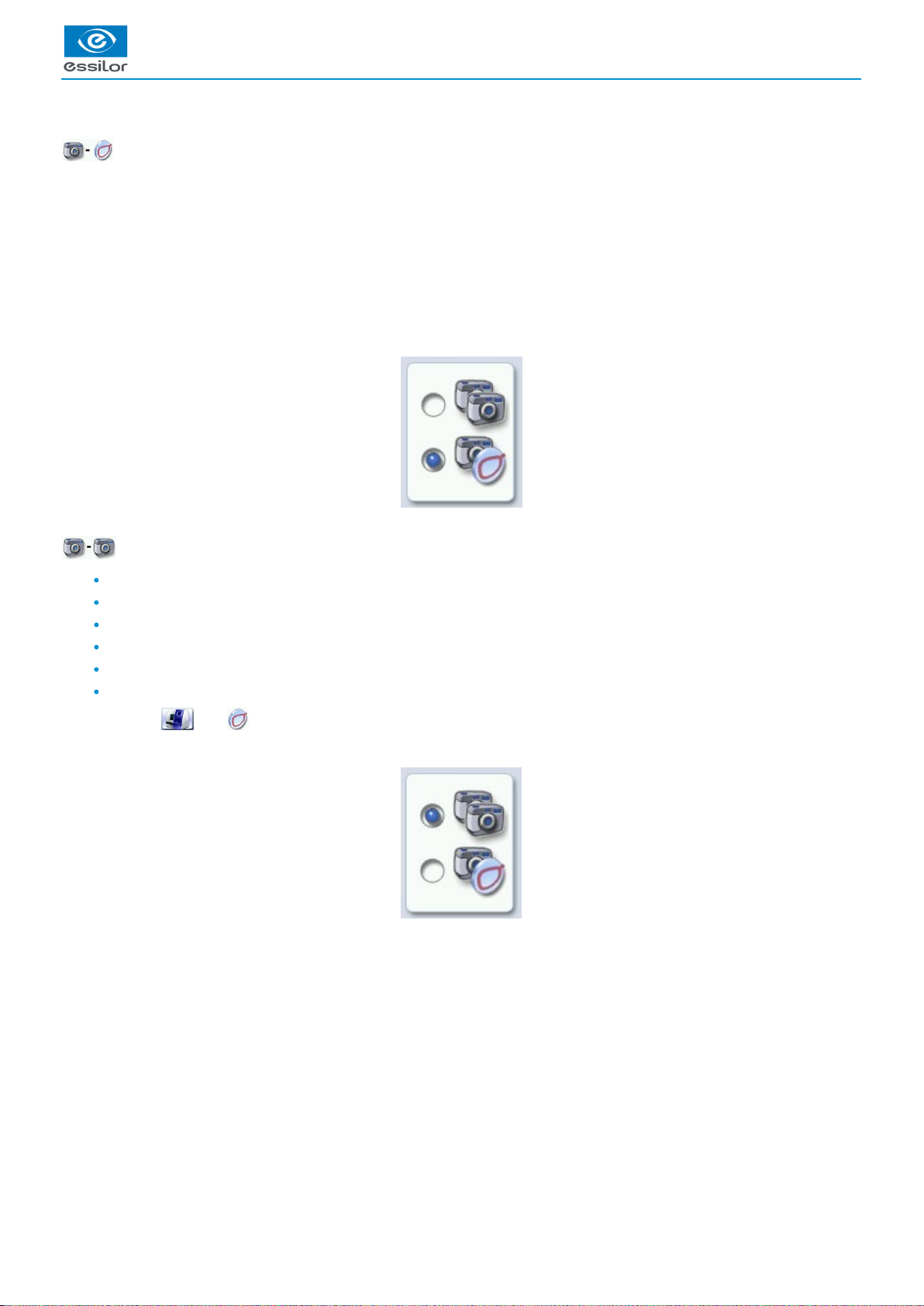
Using the touch screen
It is possible to navigate between the tracer-centerer-blocker screen or the edger screen in two different ways:
Either:
by using the icons in the top left of the screen,
by pressing lightly with your finger on the top or to the bottom of the screen.
The screen you work on and identifiable by a colour:
blue, when it’s the tracer-centerer-blocker,
purple, when it’s the edger.
The tracer-centerer-blocker part is initialized.>
A beep indicates that the initialisation was successful.>
A beep indicates that the initialisation was successful.>
A beep indicates that the initialisation was successful.
the initial work screen is displayed.
>
The initial work screen is displayed.>
A confirmation message is displayed on each screen.>
The product shuts down.>
USER MANUAL > FIRST STEPS WITH DELTA 2
Delta 2 - Edging system > v2 - 08.16 15
Page 16
1.
2.
3.
4.
5.
6.
Icon for accessing the edger’s work screen
Tracer-centerer-blocker icon
Work screen for the tracer-centerer-blocker, identifiable by its blue colour
Edger icon
Icon for accessing the tracer-centerer-blocker work screen
Work screen for the tracer-centerer-blocker, identifiable by its purple colour
If the response area does not correspond to the position of the key, you need to calibrate the touch screen. For further information,
refer to the section .Maintenance and servicing > Check and calibrate > Calibrate the touch screen (p.124)
Never press hard on the screen as this could break it.
Never press on the screen with sharp objects such as pens, scissors, clamps, etc.
Screen breakage is not covered by the guarantee.
On each screen, press the icon-buttons to access the desired menus and functions.
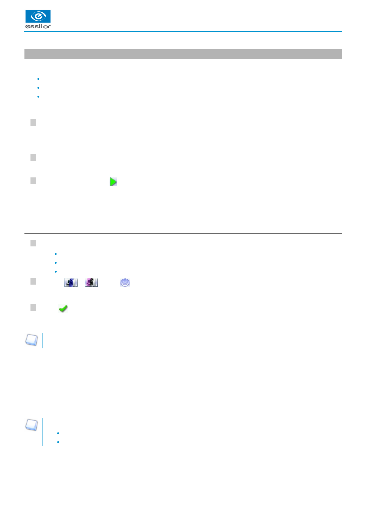
Using the keypads
When you need to enter or modify data, two types of keypads are automatically displayed, according to the information to be entered.
The numeric keypad is displayed for entering values.
Reset the fields
Go back
Confirm
Cancel and go back to the work screen
The alphanumeric keyboard is displayed for storing, calling and searching for jobs.
USER MANUAL > FIRST STEPS WITH DELTA 2
16 Delta 2 - Edging system > v2 - 08.16
Page 17

1.
2.
3.
4.
5.
6.
7.
8.
IDJob
(p.156) (p.156)
Job reference (alphanumeric characters)
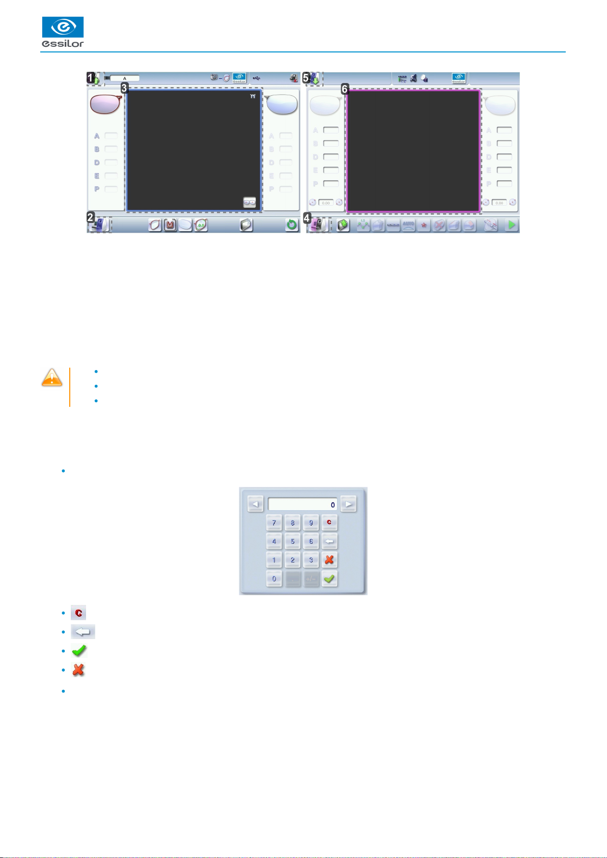
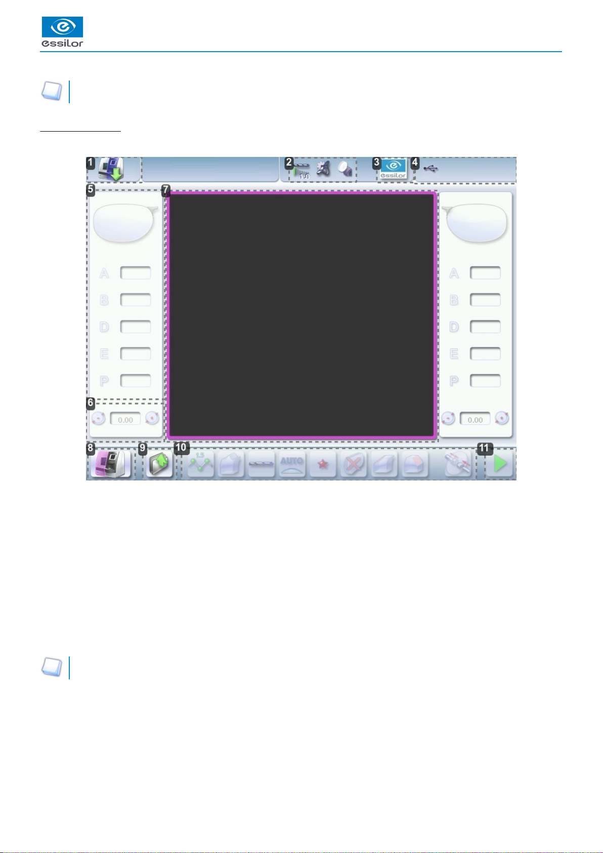
d. Work screens
Work screen (tracer-centerer-blocker)
Main work screen for the tracer-centerer-blocker screen
Icon for accessing the edger’s work screen
Job information
Settings
Devices connected
Active eye and information on the shape
Work area
Tracer-centerer-blocker icon
Actions available on the present screen
USER MANUAL > FIRST STEPS WITH DELTA 2
Delta 2 - Edging system > v2 - 08.16 17
Page 18
1.
2.
3.
4.
5.
6.
7.
8.
9.
10.
11.
For more information, consult the section performing an optical tracing > tracing environment > captioned screen. (p.21)
Edging screen (edger)
Main menus of the edging screen:
Icon for accessing the tracer-centerer-blocker work screen
Tool wear indicators
Settings
Devices connected
Active eye and information on the shape
Size increase / reduction
Work area
Edger icon
Job call
Actions available on the present screen
Start the edging cycle
For more information, refer to the section .Edging a lens > Edger environment > Menu screen (p.83)
USER MANUAL > FIRST STEPS WITH DELTA 2
18 Delta 2 - Edging system > v2 - 08.16
Page 19

III. CARRY OUT AN OPTICAL TRACING
Page 20

USER MANUAL > CARRY OUT AN OPTICAL TRACING
20 Delta 2 - Edging system > v2 - 08.16
Page 21

USER MANUAL > CARRY OUT AN OPTICAL TRACING
1.
2.
This chapter describes the procedures relating to the optical tracing of patterns, demo lenses and recut lenses:
description of the tracing environment (p.21)
manage and store shapes, (p.24)
trace a pattern, a demo or a recut lens (p.27).
1. The tracing environment
This section describes the tracing screen and explains how to manage the jobs:
description of the tracing screen (p.21)
jobs and work modes (p.22)
a. Menu screen
Menu screen
Dimensions display
A: A-dimension
B: B-dimension
D: D-dimension
E: Larger radius from the Boxing center
P: Perimeter
Function buttons
Machine shutdown
Optical tracing
Centering
Shape management
Delta 2 - Edging system > v2 - 08.16 21
Page 22
3.
4.
5.
6.
7.
8.
Type of tracing
Right-eye monocular tracing
Left-eye monocular tracing
Single monocular tracing of the right eye (blocking and possible edging of the right eye only)
Single monocular tracing of the left eye (blocking and possible edging of the left eye only)
Frame type
Metal frame
Plastic frame
Optyl frame, for particularly flexible frames
Grooved frame
Drilled frame
Tracing mode
Demo lens/Recut lens
Pattern
Setting the size increase applied to the shape
To reduce any play between the demo lens and the frame, it is possible to use this menu to set the size increase to be
applied to the shape depending on the play noted.
No play between the demo lens and the frame
Slight play between the demo lens and the frame
Significant play between the demo lens and the frame.
To set the size increase, consult the section Tracer-centerer-blocker configuration > Customize > Work modes and display
.precision (p.110)
New Job
For more information on , consult the section jobs
(p.156)
Perform a trace > Management and storage of shapes > Create a job
.(p.27)
Tracing cycle initialization
b. Jobs and working modes
Jobs
A job consists in all the actions to be carried out to produce a pair of glasses. It can be managed in two ways:
Saving: allocate an and a reference to the job to save it and re-use it later.ID
(p.156)
Automatic job archiving
Mandatory in the tracing - tracing work mode
Without saving: working in current mode (job identification by the letter A) makes it possible to process a job quickly without
memorizing it (the job processing cycle must be finished before starting a new one).
Working modes
There are 2 Work modes to manage your jobs:
the tracing-centering mode
the tracing-tracing mode
The selected work mode is shown in the information bar, to the left of the Essilor logo. You can change it in the tracer settings.
USER MANUAL > CARRY OUT AN OPTICAL TRACING
22 Delta 2 - Edging system > v2 - 08.16
Page 23
USER MANUAL > CARRY OUT AN OPTICAL TRACING
1.
2.
3.
4.
5.
Working in the tracing - centering mode
At the end of a tracing, the tracer-centerer-blocker displays the centering screen automatically then the edging preparation
screen.
You can process a job completely before proceeding with the following:
tracing or retrieving a job from the database
changing the shape and drilling position if necessary
centering
lens blocking
edging preparation
To activate this working mode, select the following parameters in the configuration screen: (p.110)
Working in tracing-tracing mode
At the end of a tracing, the tracer-centerer-blocker displays the tracing screen.
You can perform several tracing operations in succession.
The tracings are saved under the job number that you have assigned to them.
Shape modification, centering, blocking and edging preparation are processed later.
All jobs must be saved.
After a job call the centering screen appears automatically, followed by the edging preparation screen.
You can access the centering screen at any moment to centre the lens that corresponds to the active shape:
> Select then .
To activate this working mode, select the following parameters in the configuration screen: (p.110)
Delta 2 - Edging system > v2 - 08.16 23
Page 24
USER MANUAL > CARRY OUT AN OPTICAL TRACING
1.
2.
3.
4.
5.
2. Shape management and storage
This section explains how to manage the job list to store your shapes.
Description of the shape storage screen (p.24)
Job list (p.25)
Create a job (p.26)
Work on current job mode (job A) (p.27)
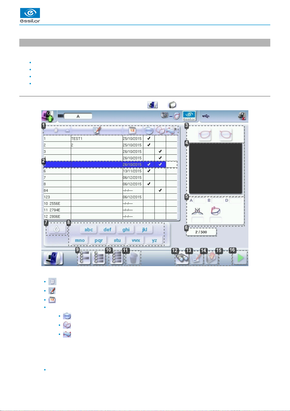
a. Menu screen
From the tracing screen or the centering screen, press on the menu then to access the shape storage screen.
Sort the jobs
ID
Reference
Date
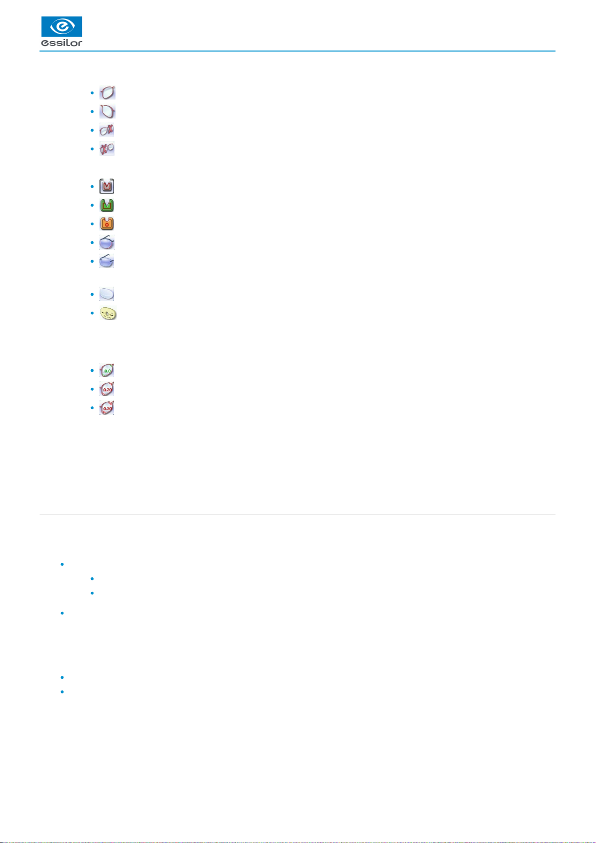
Types of jobs:
Drilled
Asymmetric tracings
Creative shapes
Selected job
Select the eye to be displayed in the preview
Shape preview
Information concerning the lens shape and frame
A, B and D dimensions
24 Delta 2 - Edging system > v2 - 08.16
Page 25

5.
6.
7.
8.
9.
10.
11.
12.
13.
14.
15.
16.
Frame base
Curve angle
Material of the frame / pattern / demo lens or recut lens
Job identifiers
Back to the default display
Display all jobs starting with the selected letter
To display the all jobs starting with the selected letter:
Press once if it is in the first position on the button,
Press twice in succession if it is in the second position,
Press three times in succession if it is in the third position.
Example:
Press 3 times on the buttonto display all jobs starting with the letter R.
> The R goes into upper case: .
> The jobs starting with the letter R are displayed.
Select several jobs
Press to select several non-consecutive jobs in the list.
Example: Press on the button then select jobs #1, #5, #7.
> Only jobs #1, #5 and #7 are selected.
Press to select a group of consecutive jobs in the list, then select the first and the last of the group.
Example: Press on the button then select jobs #1 and #10.
> All jobs from #1 to #10 are selected.
Select all jobs
Press to select all jobs for the search in progress.
Delete the selected job(s)
Press to delete the selected job(s). A confirmation message is displayed.
Search for a job by ID or by reference
Rename the selected job
Duplicate the selected job
Export the selected jobs
to the Essibox or a PMS.
Call the selected shape to the work area
b. Job list
The job list enables you to save jobs on a daily basis. It has a 500-job storage capacity.
USER MANUAL > CARRY OUT AN OPTICAL TRACING
Delta 2 - Edging system > v2 - 08.16 25
Page 26
5
4
3
2
1
c. Creating a job
There are two ways to create a job.
Scan the barcode corresponding to the desired ID using the barcode reader (optional): the job is saved in the job list.
To create a job, use the alphanumeric keypad and follow the procedure below.
From the tracing screen, press in the action bar to create a new job.
For more information on entry and use of the keyboard, consult the section First steps > Using the
.tracer-centerer-blocker > Using the touchscreen and keyboards (p.15)
Press to enter the new job .ID
(p.156)
The ID is automatically allotted by the tracer-centerer-blocker (first free location in the selected list). You can modify it: the ID
can consist of alphanumeric characters.
Press to enter the reference of the new job.
The reference may consist of alphanumeric characters. It can contain the information of your choice:
customer's name
frame brand or reference
manufacturer, etc.
Press on to confirm.
The tracer-centerer-blocker is ready for tracing. For further information, refer to the section concerning your job type.
If you don't want to save the job, you can work in current job mode. For more information, refer to the section Working in
.current job mode (job A) (p.27)
Successive tracings and saving.
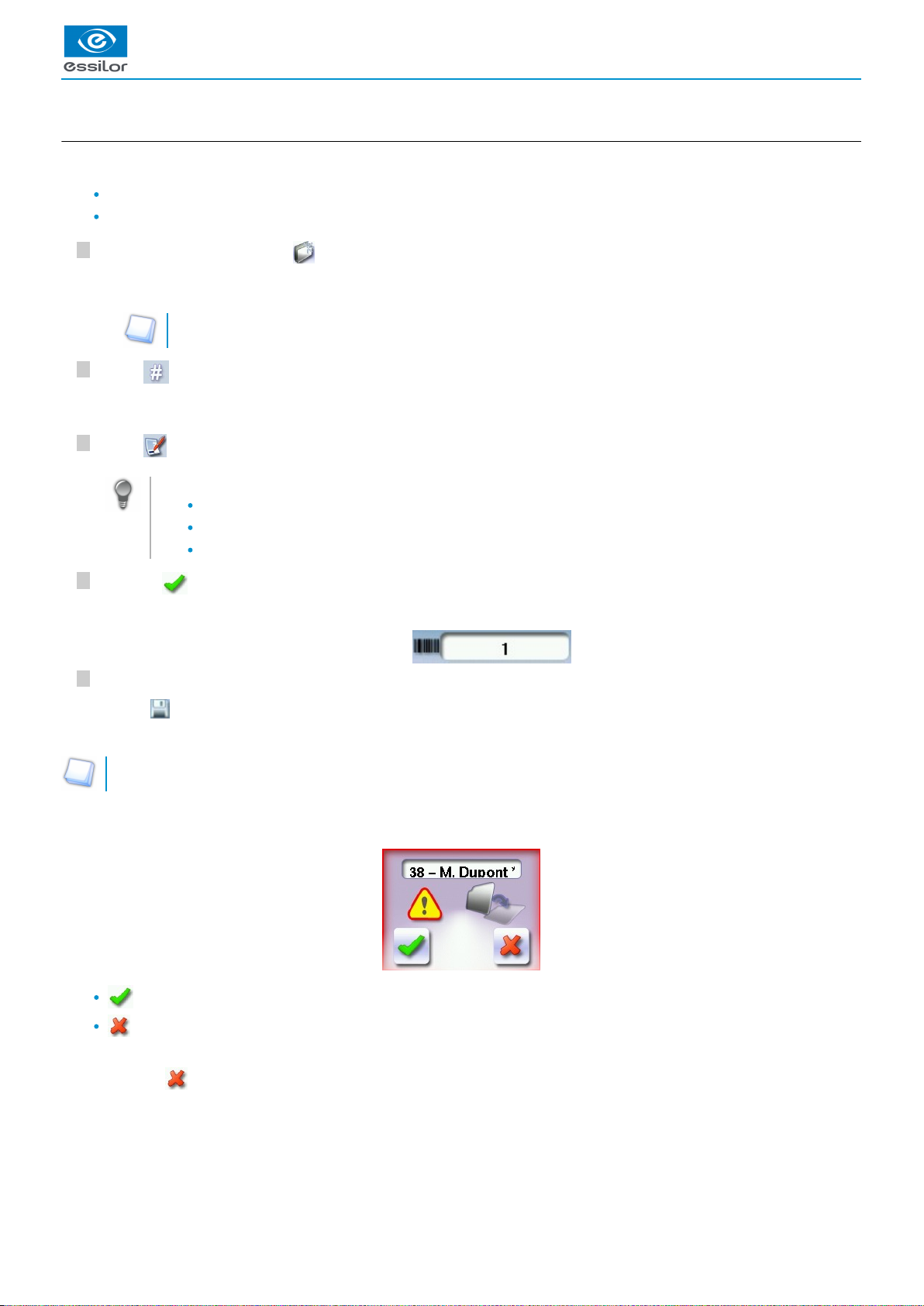
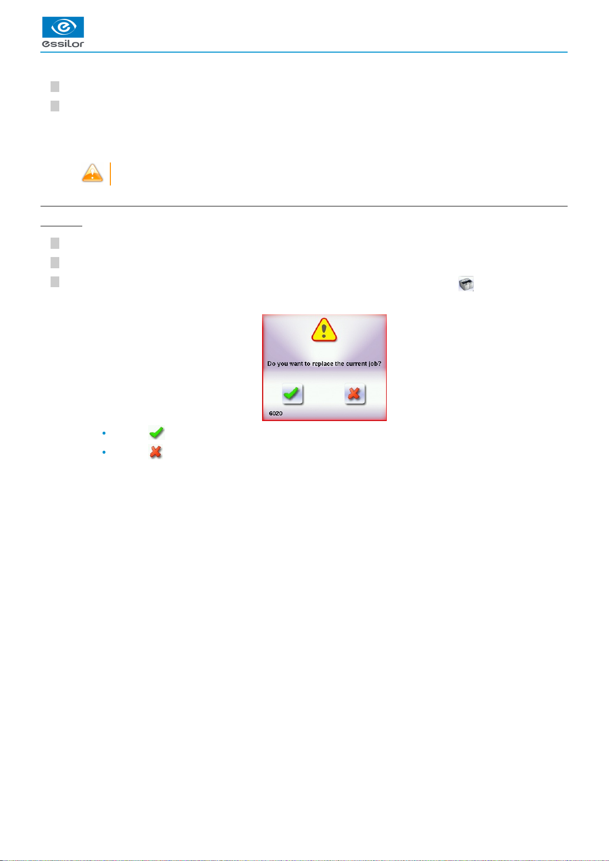
If you start a new tracing while a job is still active on the tracing screen, a message is displayed:
Replacement of the active shape: the tracing you have just started replaces the former one under the current ID.
Creation of a new job: the alphanumeric keypad is displayed, you can create a new job for the tracing you have just
started (new ID). The two jobs are thus saved.
To cancel, press again.
The alphanumeric keypad is displayed.>
The tracing screen is displayed, the allocated ID and the job list symbol appear in the information bar.>
The symbol is displayed at the bottom right of the job ID while the job is being modified. It disappears once the job has
been saved.
>
USER MANUAL > CARRY OUT AN OPTICAL TRACING
26 Delta 2 - Edging system > v2 - 08.16
Page 27
USER MANUAL > CARRY OUT AN OPTICAL TRACING
5
4
3
2
1
d. Working in current job mode (job A)
As soon as the tracer-centerer-blocker is initialized, you can work in current job mode: the letter A is displayed by default in the
information bar. The job is not saved.
If you want to save job A, see the .job creation procedure (p.26)
If you want to go back to job A after working on a saved job:
scan the barcode A using the barcode reader (option) or
use the numeric keypad and follow the procedure below.
From the tracing screen, press in the action bar to create a new job.
For more information on entry and use of the keyboard, consult the section First steps > Using the
.tracer-centerer-blocker > Using the touchscreen and keyboards (p.15)
Press to select the field.ID
(p.156)
Press to delete the ID.
Press on to confirm.
The tracer is ready for tracing.
For further information, refer to the section concerning your type of job.
3. Optical tracing
Preparing optical tracing of demo or recut lens
This type of tracing makes it possible to retrieve the existing shape and drilling data of a lens.
In the case of a presentation case, in order not to cause an centering position error, make sure to use a clear lens of any
commercial identification (brand, logo etc).
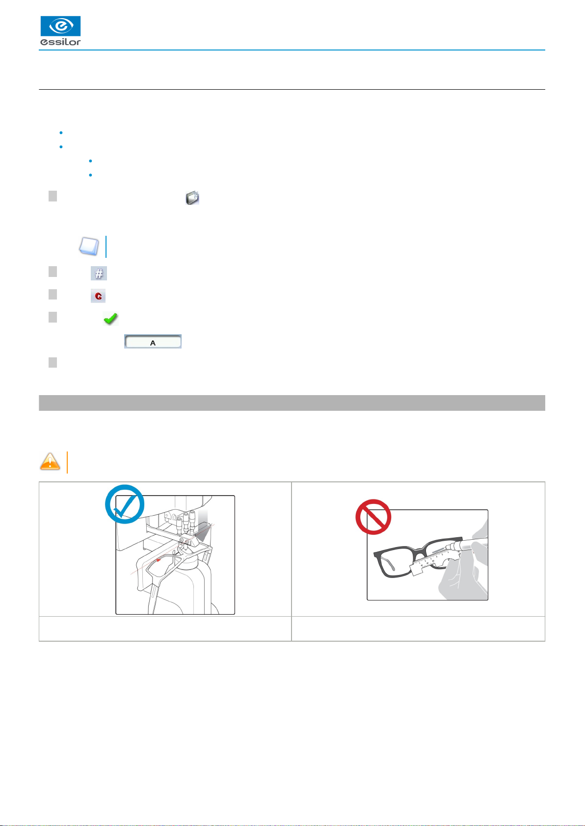
The use of focimeter marking points guarantees the feature’s
horizontality.
A free-hand marking does not to guarantee the proper
horizontality of the feature.
The alphanumeric keypad is displayed.>
The letter A is displayed in the information bar.
>
Delta 2 - Edging system > v2 - 08.16 27
Page 28

USER MANUAL > CARRY OUT AN OPTICAL TRACING
7
6
5
4
3
2
1
Prerequisite: for the tracer to correctly detect the horizontality of the lens, the lens must be clean and marked using a white felt tip
marker with:
either three focimeter dots
or a horizontal line which must not touch the edges of the lens (a space of at least 5 mm is required)
Avoid using red markers
Tracing
Press to select optical tracing .
Press to indicate the eye to trace.
Press to select a type of frame.
Press to select the pattern or press to select the demo or recut lens.
Press to select the type of play between the demo lens and the frame.
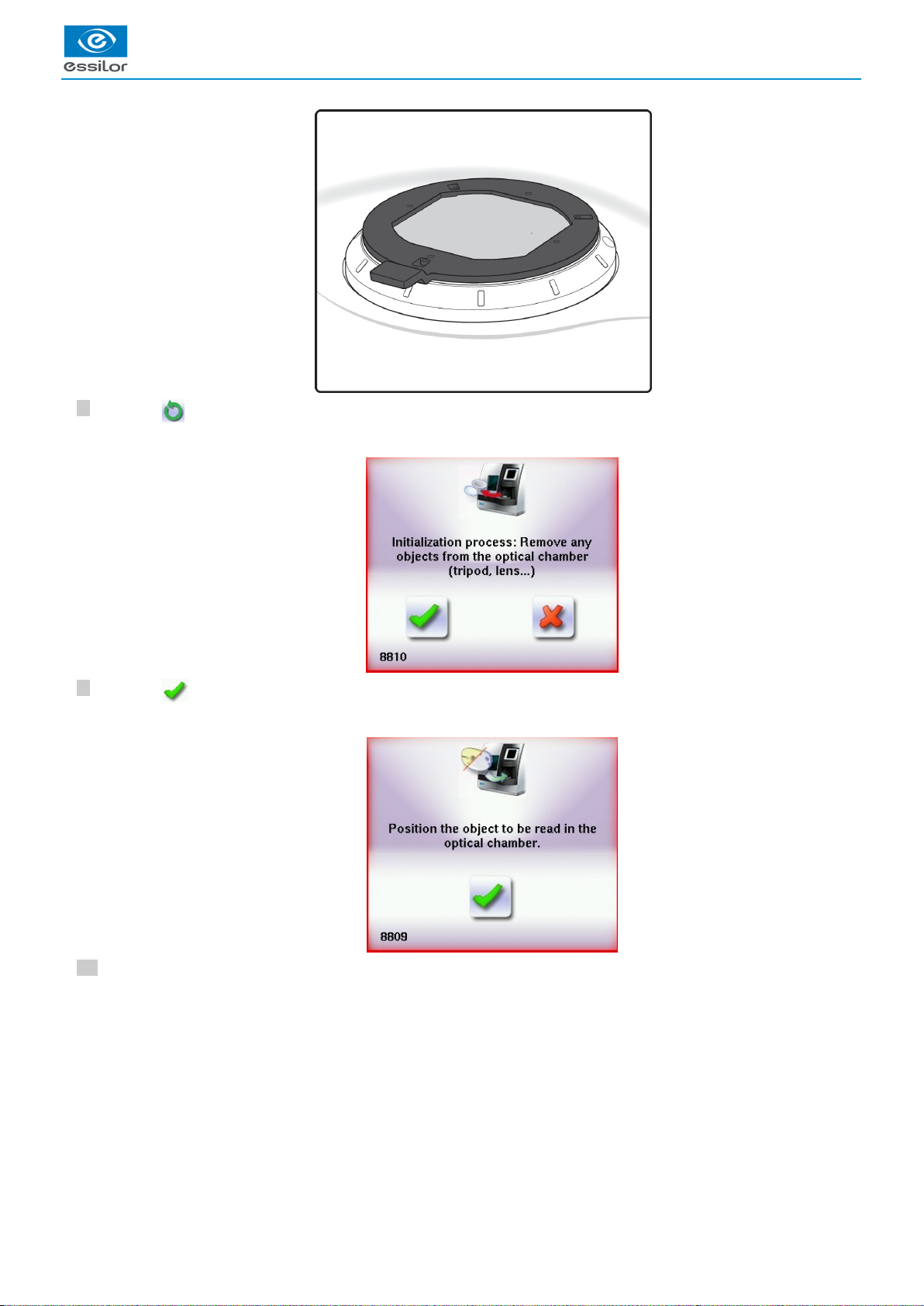
Lower the tube.
Position the reflector.
28 Delta 2 - Edging system > v2 - 08.16
Page 29
USER MANUAL > CARRY OUT AN OPTICAL TRACING
10
9
8
Press on to start the tracing cycle.
Press on to confirm.
Position the lens.
The following message appears:>
The following message is displayed:>
Delta 2 - Edging system > v2 - 08.16 29
Page 30
USER MANUAL > CARRY OUT AN OPTICAL TRACING
12
11
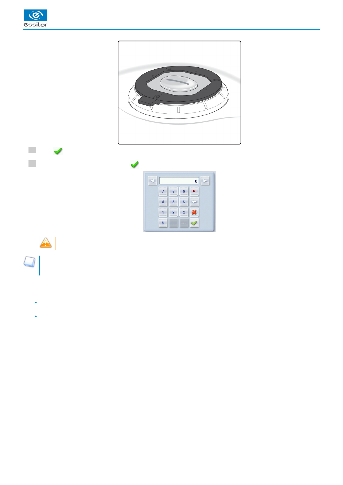
Press to confirm.
Enter the D-dimension value, then press to confirm.
Take care systematically to measure the D-dimension of your frame to confirm the value entered by the manufacturer
on the arms of the frame.
Tracing - tracing mode
In tracing - tracing mode, the result of the tracing is displayed in the work area of the tracing screen. For more information on
work modes, refer to the section .Tracing > Tracing environment > Jobs and work modes (p.22)
Before Centering
Once tracing has been carried out, you can:
enter the curve angle and the frame base, for optimal centering precision Refer to the section Centering a lens > Centering a
.lens for a high-base frame (p.44)
add drilling to the shape. For more information, refer to the section .Preparing a drilled job (p.71)
30 Delta 2 - Edging system > v2 - 08.16
Page 31

USER MANUAL > CARRY OUT AN OPTICAL TRACING
5
4
3
2
1
4. Enter the curve and frame base
During monocular tracing, the curve angle and the frame base cannot be measured. To optimize centering precision, it is
recommended to enter these values after tracing a pattern, a recut lens or a demo lens.
Prerequisite: before entering the curve angle and the frame base, it’s necessary to perform the optical tracing of the pattern, a
.demo lens or a recut lens (p.27)
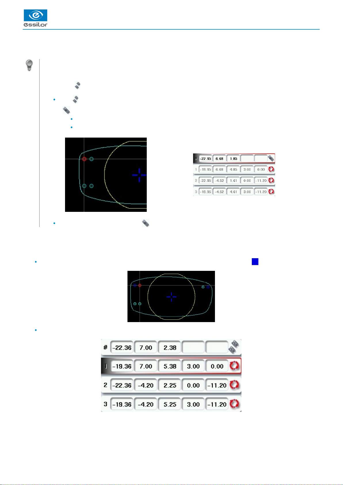
Entering the curve angle and frame base values
Press the button.
Select the curve angle value to modify it.
Place the frame on the screen:
the vertical blue line at the centre of the frame
the bridge of the frame superimposed on the base line.
Use the and buttons to align the light blue lines with the nasal and temporal ends of the circles.
You can also press for a few seconds on the value and change it using the digital keyboard.
Select the of frame base value to modify it.
The following screen is displayed:>
The value is displayed in red.>
The curve angle value is changed.>
Delta 2 - Edging system > v2 - 08.16 31
Page 32

7
6
1.
2.
3.
4.
5.
Use the and buttons to modify the frame base value.
You can also press for a few seconds on the value and change it using the digital keyboard.
Press on to confirm.
5. Case of a mechanical tracing
a. Connection with a PHI tracer
Metal frame - acquisition of the groove profile
Plastic frame
Local tracing (not used here)
Selection right eye/left eye
Cycle start-up button
The value is displayed in red.>
USER MANUAL > CARRY OUT AN OPTICAL TRACING
32 Delta 2 - Edging system > v2 - 08.16
Page 33
3
2
1
2
1
Perform tracing according to the type of selected frame.
Click on the cycle start-up button.
The form arrives directly on the Delta 2 work screen, therefore it’s not possible to recall a previous shape..
b. Connection with a Tess tracer
Current job
Turn on the Tess tracer.
Perform a current tracing job on the Tess tracer.
On the machine’s work screen, in edger mode, press for a long time on the icon of the Tess tracer.
press on to override the current job,
press on to cancel and return to the menu
A beep rings out.>
The form appears directly on the work screen of the product.>
The following message appears:>
USER MANUAL > CARRY OUT AN OPTICAL TRACING
Delta 2 - Edging system > v2 - 08.16 33
Page 34

4
3
2
1
4
3
2
1
Numbered job
Turn on the Tess tracer.
Perform a current tracing job on the Tess tracer.
On the machine’s work screen, in edger mode, press for a long time on the icon of the Tess tracer.
Complete the job number and press on .
press on to end the current job,
press on to cancel and obtain a new job number.
The following page appears:>
The following window is displayed:>
USER MANUAL > CARRY OUT AN OPTICAL TRACING
34 Delta 2 - Edging system > v2 - 08.16
Page 35

IV. CENTER AND BLOCK A LENS
Page 36

USER MANUAL > CENTER AND BLOCK A LENS
36 Delta 2 - Edging system > v2 - 08.16
Page 37

3
2
1
This chapter describes the lens centering procedures according to the type of lens.
Description of the centering environment (p.37)
Centering a single vision lens (p.44)
Centering a progressive lens (p.46)
Centering a bifocal lens (p.50)
Centering an executive lens (p.51)
Centering a mid-distance lens (p.53)
Centering a lens for a high-base frame (p.44)
This chapter also describes the procedure.lens blocking (p.57)
1. Centering environment
This section describes the centering screen and the various centering modes available:
Description (p.37)
Menu screen (p.41)
Job call (p.43)
a. Description of the centering blocking system
Pre-requisite: before carrying out the centering of the lens, supply a posiblock and a pad Essilor.
Centering
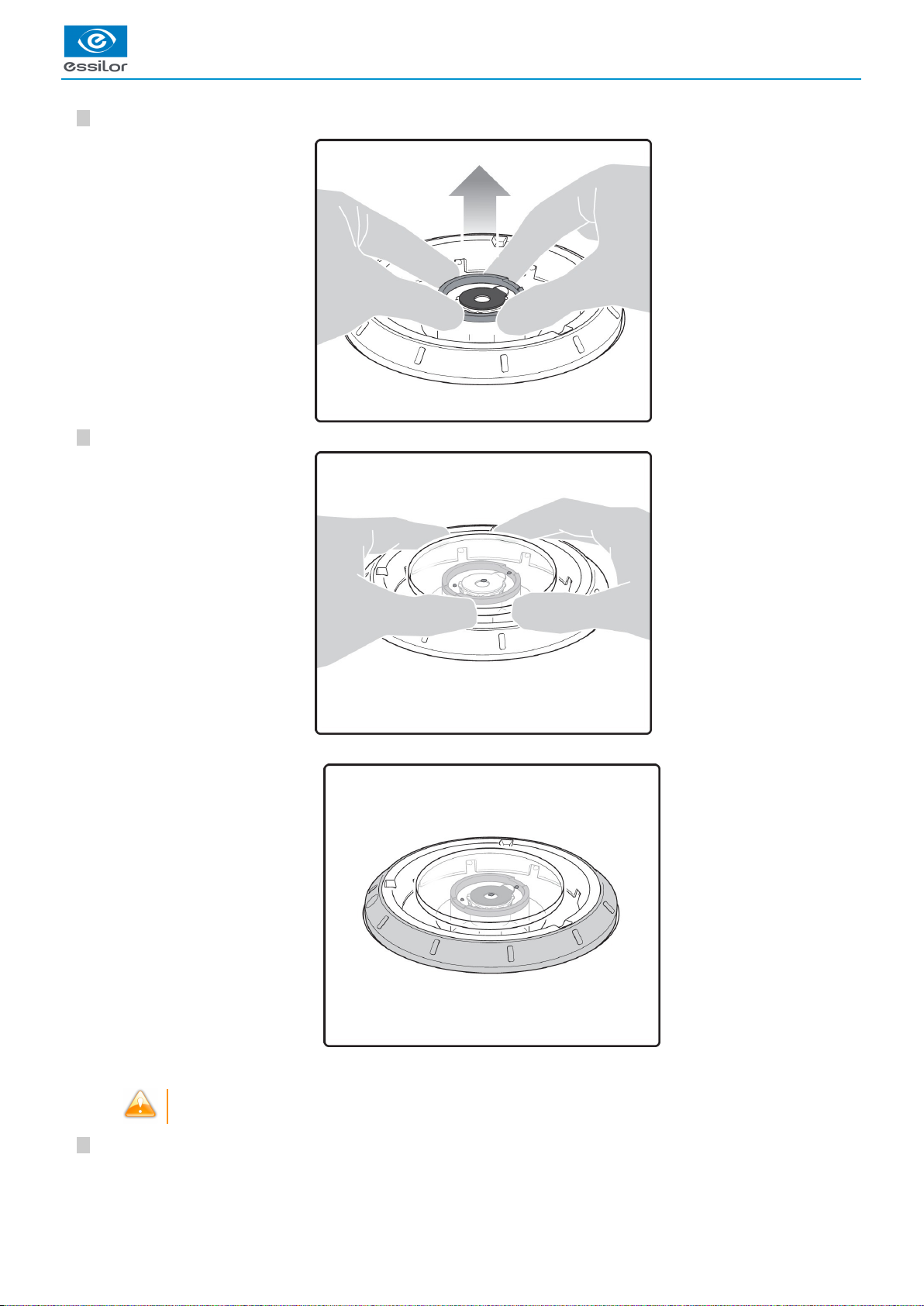
Lower the tube manually.
Insert the posiblock and its pad in the centering device.
Raise manually the tube back into centering position.
USER MANUAL > CENTER AND BLOCK A LENS
Delta 2 - Edging system > v2 - 08.16 37
Page 38

USER MANUAL > CENTER AND BLOCK A LENS
5
4
Position the lens on the tube.
As opposed to the other machines, the lens must be placed with convex side on the tube.
Center the lens
To center the lens, align the markup of the lens with the target according to the lens type used (bifocal, progressive
etc…).
Centering is manual.
38 Delta 2 - Edging system > v2 - 08.16
Page 39

1
Block the lens
Hold the lens with both hands and, put pressure down on the lens.
Blocking is manual.
The tube drops and the posiblock is fixed on the lens.>
USER MANUAL > CENTER AND BLOCK A LENS
Delta 2 - Edging system > v2 - 08.16 39
Page 40

1.
2.
3.
4.
Centering screen
Active eye and type of display of PD and pupillary height
Information on the right eye
Visual cue of the frame positioned facing the screen
Information on the left eye
It is possible to start independently with the right eye or the left eye. On the other hand, the change of the eye must be carried
out manually.
USER MANUAL > CENTER AND BLOCK A LENS
40 Delta 2 - Edging system > v2 - 08.16
Page 41

1.
2.
3.
4.
5.
6.
7.
8.
b. Menu screen
Blocking mode
Blocking in the centerboxing
(p.156)
Blocking in the optical center
For further information, refer to the section .Lens Centering > Blocking a lens > Preparing blocking (p.57)
Minimal diameter of the lens to be used
Active eye and type of display of PD and pupillary height
Four modes available:
Boxing mode
Datum mode
ΔY mode
ΔX + ΔY mode
For more information on the type of display, consult the section Digital system configuration > Customize the
tracer-centerer-blocker > Decentration mode. (p.111)
Half PD
Pupillary height
Posiblock display to be used depending on the job.
Work area
: Nasal side indicator
(green) or (cyan): Lens shape
(orange): Centering target according to the type of lens
(blue): Boxing center of the shape
Contrast Adjustment
USER MANUAL > CENTER AND BLOCK A LENS
Delta 2 - Edging system > v2 - 08.16 41
Page 42

USER MANUAL > CENTER AND BLOCK A LENS
9.
10.
11.
12.
13.
14.
15.
16.
17.
Black and white inversion
Adjusting luminosity
Improves the traceability of the marks on the lenses, in particular for tinted lenses.
Job call on a tracer
Two possible choices:
: if the product is connected to a Tess tracer
: if the product is not connected to a Tess tracer
Entering the curve angle and frame base
Lens type selection
Single vision lens
(p.157)
Progressive lens
(p.156)
Bifocal lens
(p.157)
Executive lens
(p.156)
Mid-distance lens
(p.156)
Value modification
To reduce or increase the previously selected value.
Toggle between the PD and pupillary height
Shape modification
Provides access to the shape modification screen. For more information, consult the following chapter Modifying the lens
.shape (p.63)
Drilling preparation (option)
Provides access to the drilling screen. For more information, consult the chapter .Preparing a drilled job (p.71)
Zoom mode
The zoom is carried out directly by touching the screen on the desired area. There are three zoom modes:
central
temporal
nasal
To activate the display on the 1:1 scale by default, consult the section Tracer-centerer-blocker configuration > Customize >
.Work modes and display precision (p.110)
42 Delta 2 - Edging system > v2 - 08.16
Page 43

USER MANUAL > CENTER AND BLOCK A LENS
1.
2.
3.
Zoom on the temporal area
Zoom on the central zone
Zoom on the nasal area
c. Calling up a shape
In the job list
There are two ways of calling a shape in the job list:
Calling a shape via a barcode:
> scan the barcode using the barcode reader (optional).
Call a shape by selecting it in the job list:
> From the tracing screen or the centering screen, press on the menu then to access the shape storage screen.
> You can then look for a job by ID, reference, date, job type (drilled, asymmetric tracings, creative shapes). For more
information, consult the section .Perform a trace > Management and storage of shapes>Legend screen (p.24)
On the tracer (if the connection to the tracer is activated)
There are 3 ways to call a traced job on a tracer and to carry out a :job
(p.156)
Calling the current shape:
> Press to display the shape being processed on the tracer.
Job called saved on the tracer:
Press for a few seconds to open the numeric keypad.
> You can then call a shape by the which was allotted to it.ID
(p.156)
Calling a shape via a barcode:
> scan the barcode using the barcode reader (optional).
> A warning message is displayed.
Delta 2 - Edging system > v2 - 08.16 43
Page 44

USER MANUAL > CENTER AND BLOCK A LENS
Press to replace the job displayed by the job called.
Press to cancel: the job is not sent to the tracer-centerer-blocker.
> The shape is displayed in the centering screen.
2. Centering a lens for a high-base frame
3D compensation
The PD and pupillary height measurements as well as the lens centering are done in two dimensions. But the frame is processed in
three dimensions:
3D compensation takes into account all frame characteristics (x, y, z, curve, pantoscopic tilt, etc.) to ensure that the center of the
wearer's pupil is at the optical center of the lens. For an optimal job, the on-screen positioning of the centering indicators always
takes account of 3D compensation.
3. Centering a single vision lens
Prerequisite: before carrying out lens centering, a shape must be displayed on the centering screen.
If necessary, we recommend that you first:
modify or retouch the traced shape (p.63)
prepare the drilling points (p.71) to be created (option)
place the stickers recommended by the manufacturer on hydrophobic lenses. (p.57)
Concerning the use of the stickers, be careful to change the centering tube with a larger diameter one to optimise the
effectiveness of the sticker.
This section describes the procedures for centering a single vision lens:
For centering using three focimeter dots
Prerequisite: the lens must be marked usinga focimeter.
The three focimeter dots must be:
aligned,
at the same distance from the central dot,
0.5 to 1.5 mm in diameter.
of white colour
At the time of the release of the lens on the centering tube, be sure to align the three focimeter dots with the notches
designed for this purpose in order not to alter the marking.
In the case of a demonstration lens or a recut lens, make sure that the marking feature is perfectly horizontal to avoid any
axis deviation during centering.
For more information, consult the section performing an optical tracing > Optical tracing > Prepare the optical tracing of a demo lens
or of recut lens. (p.27)
If need be, re-mark the points with a white colour gouache paint.
44 Delta 2 - Edging system > v2 - 08.16
Page 45

USER MANUAL > CENTER AND BLOCK A LENS
7
6
5
4
3
2
1
1.
2.
To center in re-marked micro-engravings mode
Pre-requisite: micro-engravings must be re-marked with a white felt tip pen. The diameter of the dots must be between 0.5 and
1.5 mm.
We advise you to use the white felt tip marker supplied with the tracer-centerer-blocker to mark the lens.
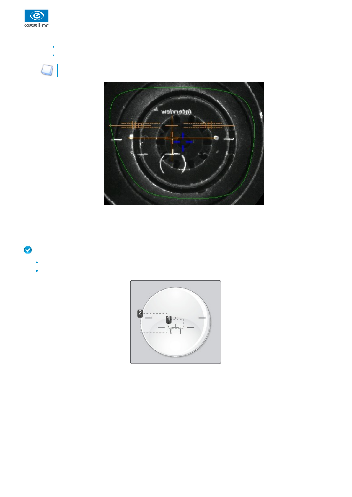
Description of the centering target
Optical center of the lens (orange cross) and boxing center of the shape (blue cross)
Centering marks
Centering the lens
Press to select the type of single vision lens.
Enter the half PD and pupillary height.
Lower the tube.
Insert the posiblock and its pad in the centering device.
Raise the tube back into centering position.
Position the lens on the tube, with the convex side on the tube.
In three focimeter dots mode:move the lens slowly until the three focimeter dots are perfectly aligned on the target.
place the central point in the square ,
place the two external points between the two dotted lines, as close as possible to the central line.
In micro-engraving mode:move the lens slowly until the micro-engravings are perfectly aligned on the target.
The centering target is displayed:>
The target moves.>
Delta 2 - Edging system > v2 - 08.16 45
Page 46

1.
2.
3.
THREE FOCIMETER DOTS MICRO-ENGRAVINGS
To block the lens, refer to the section .Centering a lens > Blocking a lens (p.57)
4. Centering a progressive lens
Prerequisite: before carrying out lens centering, a shape must be displayed on the centering screen.
If necessary, we recommend that you first:
modify or retouch the traced shape (p.63)
prepare the drilling points (p.71) to be created (option)
place the stickers recommended by the manufacturer on hydrophobic lenses. (p.57)
Concerning the use of the stickers, be careful to change the centering tube with a larger diameter one to optimise the
effectiveness of the sticker.
This section describes the procedures for the centering of a progressive lens:
using re-marked micro-engravings mode (p.47)
using manufacturer markings mode (p.48)
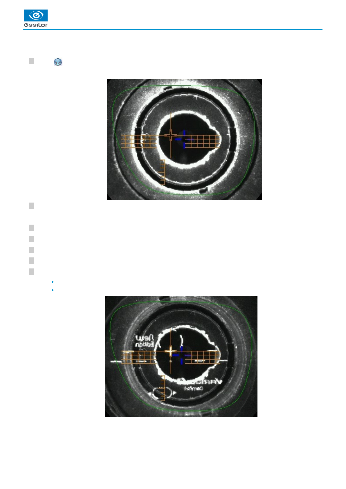
Description of the centering target
Centering cross (orange cross) and boxing center of the shape (blue cross)
Centering graduated marks
The horizontal lines are 2mm apart so you can measure the PRP distance.
Near vision mark
The lens is centered and ready to be blocked.
>
USER MANUAL > CENTER AND BLOCK A LENS
46 Delta 2 - Edging system > v2 - 08.16
Page 47

7
6
5
4
3
2
1
a. Centering a progressive lens using re-marked micro-engravings
Prerequisite:
Remove all the original markings,
Re-mark the micro-engravings with the marker; the diameter of points must be between 0.5 and 1.5 mm.
We advise you to use the white felt tip marker supplied with the centerer-blocker to mark the lens.
Centering the lens
Press to select the type of progressive lens.
Enter the half PD and pupillary height.
Lower the tube.
Insert the posiblock and its pad in the centering device.
Raise the tube back into centering position.
Position the lens on the tube, with the convex side on the tube.
Move the lens slowly until the micro-engravings are:
Symmetrical in relation to the graduations,
Aligned on the line corresponding to the PRP of the lens.
The centering target is displayed:>
The target moves.>
USER MANUAL > CENTER AND BLOCK A LENS
Delta 2 - Edging system > v2 - 08.16 47
Page 48

USER MANUAL > CENTER AND BLOCK A LENS
1.
2.
The PRP value of Essilor progressive lenses is 4mm. This may vary depending on the manufacturer of the lenses.
To block the lens, refer to the section .Centering a lens > Blocking a lens (p.57)
b. Centering a lens using manufacturer markings
Prerequisite:
The markings must be clear
The lens must at least have the following markings:
Far vision mark
Centering marks
The lens is centered and ready to be blocked.>
48 Delta 2 - Edging system > v2 - 08.16
Page 49
7
6
5
4
3
2
1
Centering the lens
Press to select the type of progressive lens.
Enter the half PD and pupillary height.
Lower the tube.
Insert the posiblock and its pad in the centering device.
Raise the tube back into centering position.
Position the lens on the tube, with the convex side on the tube.
Slowly move the lens untilmanufacturer markings are:
Perfectly centered in the centering cross,
Parallel to the horizontal lines.
To block the lens, refer to the section .Centering a lens > Blocking a lens (p.57)
The centering target is displayed:>
The target moves.>
The lens is centered and ready to be blocked.>
USER MANUAL > CENTER AND BLOCK A LENS
Delta 2 - Edging system > v2 - 08.16 49
Page 50

USER MANUAL > CENTER AND BLOCK A LENS
4
3
2
1
1.
2.
3.
5. Centering bifocal / trifocal lenses
Prerequisite: before carrying out lens centering, a shape must be displayed on the centering screen.
If necessary, we recommend that you first:
modify or retouch the traced shape (p.63)
prepare the drilling points (p.71) to be created (option)
place the stickers recommended by the manufacturer on hydrophobic lenses. (p.57)
Concerning the use of the stickers, be careful to change the centering tube with a larger diameter one to optimise the
effectiveness of the sticker.
This section describes the centering procedure for a bifocal or trifocal lens with a straight, curved or round segment.
Description of the centering target
Centering cross (orange cross) and the boxing center of the shape (blue cross)
Near vision mark
Centering marks
Centering the lens
Press to select the type of bifocal lens.
Enter the half PD for near vision and the frame height.
Lower the tube.
Insert the posiblock and its pad in the centering device.
The centering target is displayed:>
The target moves.>
50 Delta 2 - Edging system > v2 - 08.16
Page 51

7
6
5
Raise the tube back into centering position.
Position the lens on the tube, with the convex side on the tube.
Move the lens slowly until the top of the segment is in the center of the target.
D-SEGMENT ROUND SEGMENT
If your bifocal segment (round or right) is not visible or if you wish to improve its visibility on the screen, you must
re-mark it using a white felt tip marker, while following the contour of the segment.
To block the lens, refer to the section .Centering a lens > Blocking a lens (p.57)
6. Centering an executive lens
Prerequisite: before carrying out lens centering, a shape must be displayed on the centering screen.
If necessary, we recommend that you first:
modify or retouch the traced shape (p.63)
prepare the drilling points (p.71) to be created (option)
place the stickers recommended by the manufacturer on hydrophobic lenses. (p.57)
Concerning the use of the stickers, be careful to change the centering tube with a larger diameter one to optimise the
effectiveness of the sticker.
This section describes the procedure for centering an executive lens.
Prerequisite: the lens must be marked usinga focimeter.
The three focimeter dots must be:
aligned,
at the same distance from the central dot,
0.5 to 1.5 mm in diameter.
of white colour
At the time of the release of the lens on the centering tube, be sure to align the three focimeter dots with the notches
designed for this purpose in order not to alter the marking.
In the case of a demonstration lens or a recut lens, make sure that the marking feature is perfectly horizontal to avoid any
axis deviation during centering.
For more information, consult the section performing an optical tracing > Optical tracing > Prepare the optical tracing of a demo lens
or of recut lens. (p.27)
The lens is centered and ready to be blocked.>
USER MANUAL > CENTER AND BLOCK A LENS
Delta 2 - Edging system > v2 - 08.16 51
Page 52

7
6
5
4
3
2
1
1.
2.
3.
Description of the centering target
Centering mark
Boxing center of the shape (blue cross)
Centering mark
Centering the lens
Press to select the type of executive lens.
Enter the half PD (for near vision or far vision) and the frame height.
Lower the tube.
Insert the posiblock and its pad in the centering device.
Raise the tube back into centering position.
Position the lens on the tube, with the convex side on the tube.
Move the lens slowly until it is perfectly centered:
Line up the transition segment between near vision and far vision with the horizontal mark in the center
Position the central focimeter dot on the vertical axis of the target
The centering target is displayed:>
The target moves.>
USER MANUAL > CENTER AND BLOCK A LENS
52 Delta 2 - Edging system > v2 - 08.16
Page 53

1.
2.
FAR VISION CENTERING NEAR VISION CENTERING
To block the lens, refer to the section .Centering a lens > Blocking a lens (p.57)
7. Centering a mid-distance lens
Prerequisite: before carrying out lens centering, a shape must be displayed on the centering screen.
If necessary, we recommend that you first:
modify or retouch the traced shape (p.63)
prepare the drilling points (p.71) to be created (option)
place the stickers recommended by the manufacturer on hydrophobic lenses. (p.57)
Concerning the use of the stickers, be careful to change the centering tube with a larger diameter one to optimise the
effectiveness of the sticker.
This section describes the procedures for the centering of a mid-distance lens:
using re-marked micro-engravings mode (p.54)
using manufacturer markings mode (p.55)
Description of the centering target
Centering cross (orange cross) and boxing center of the shape (blue cross)
Centering graduated marks
The horizontal line is situated at 6mm enabling you to measure the PRP distance.
The lens is centered and ready to be blocked.>
USER MANUAL > CENTER AND BLOCK A LENS
Delta 2 - Edging system > v2 - 08.16 53
Page 54

7
6
5
4
3
2
1
a. Centering a lens using re-marked micro-engravings
Prerequisite:
remove all the original markings,
re-mark the micro-engravings with the marker; the diameter of points must be between 0.5 and 1.5 mm.
We advise you to use the white felt tip marker supplied with the tracer-centerer-blocker to mark the lens.
Centering the lens
Press to select the type of mid-distance lens.
Enter the half PD and the frame height.
Lower the tube.
Insert the posiblock and its pad in the centering device.
Raise the tube back into centering position.
Position the lens on the tube, with the convex side on the tube.
Move the lens slowly until the micro-engravings are:
The centering target is displayed:>
The target moves.>
USER MANUAL > CENTER AND BLOCK A LENS
54 Delta 2 - Edging system > v2 - 08.16
Page 55
USER MANUAL > CENTER AND BLOCK A LENS
1.
2.
symmetrical in relation to the graduations,
aligned on the line corresponding to the PRP of the lens.
The PRP value of Essilor mid-distance lenses is 6 mm. This may vary depending on the manufacturer of the lenses.
To block the lens, refer to the section .Centering a lens > Blocking a lens (p.57)
b. Centering a lens using manufacturer markings
Prerequisite
The markings must be clear
The lens must at least have the following markings:
Centering cross
Centering marks
The lens is centered and ready to be blocked.>
Delta 2 - Edging system > v2 - 08.16 55
Page 56

7
6
5
4
3
2
1
Centering the lens
Press to select the type of mid-distance lens.
Enter the half PD and the frame height.
Lower the tube.
Insert the posiblock and its pad in the centering device.
Raise the tube back into centering position.
Position the lens on the tube, with the convex side on the tube.
Slowly move the lens untilmanufacturer markings are:
Perfectly centered in the centering cross,
Parallel to the horizontal lines.
To block the lens, refer to the section .Centering a lens > Blocking a lens (p.57)
The centering target is displayed:>
The target moves.>
The lens is centered and ready to be blocked.>
USER MANUAL > CENTER AND BLOCK A LENS
56 Delta 2 - Edging system > v2 - 08.16
Page 57

1.
2.
3.
4.
5.
8. Blocking a lens
This section describes the procedures for lens blocking depending on the selected option:
blocking preparation (p.57)
blocking (p.59)
a. Prepare blocking
Several accessories are available to perform blocking:
posiblocks and pads
tubes
Posiblocks and pads
22 mm posiblock
18x14 mm posiblock
Magnet
Fin
Tab
The posiblocks and their corresponding pads are supplied with the edger.
Always use Essilor pads: they are specially designed to ensure the performance of your machine for quality jobs.
The pads are non re-usable.
Do not stick pads on posiblocks in advance as they may loose some of their holding power.
The posiblock must never be placed on the rear (inner) surface of the lens.
Blocking in Boxing center or in optical center
Depending on your working practice, you can choose to block the lenses:
in the boxing center of the shape (recommended),
in the optical center.
In the event of blocking in the optical center, the posiblock position on the shape may be off center.
BLOCKING IN BOXING CENTER (BLUE CROSS) BLOCKING IN THE OPTICAL CENTER (TEST CARD)
USER MANUAL > CENTER AND BLOCK A LENS
Delta 2 - Edging system > v2 - 08.16 57
Page 58

USER MANUAL > CENTER AND BLOCK A LENS
The selected blocking mode is displayed in the information bar:
blocking in the boxing center
blocking in the optical center
By default, the tracer-centerer-blocker blocks the lenses in the boxing center.
To choose a different blocking mode, consult the section Tracer-centerer-blocker configuration > Customize > Work modes and
.display precision (p.110)
Tubes
There are two diameters of tube:
the smallest tube has a diameter of 42 mm. It is the standard tube mounted by default on the machine
the large tube has a diameter of 53 mm. It is an optional accessory and will be used only in certain typical cases, stickers for
example. It is mounted instead of the small tube, by a simple system of bayonet assembly.
42 mm Tube diameter 53 mm Tube diameter
58 Delta 2 - Edging system > v2 - 08.16
Page 59

USER MANUAL > CENTER AND BLOCK A LENS
4
3
2
1
b. Blocking
Prerequisite
The lens must be centered.
Take the posiblock adapted tothe shape, indicated at the bottom right ofthe screen: or .
Place the posiblock on the pad and press firmly, with the self-adhesive face upwards and tabs towards the left.
Remove the film from the self-adhesive face.
Lower the tube.
Position the posiblock within the boundary of the tube designed for this purpose.
Delta 2 - Edging system > v2 - 08.16 59
Page 60
7
6
5
Raise the tube back into centering position.
After centering the lens, apply pressure with two hands on the tube in order to lower it.
For a hydrophobic lens, be careful to use the large diameter tube and the stickers designed for this purpose.
Center and block the second lens.
The posiblock adheres to the surface of the lens.>
The lens is blocked.>
The edging preparation screen is displayed automatically.>
USER MANUAL > CENTER AND BLOCK A LENS
60 Delta 2 - Edging system > v2 - 08.16
Page 61

8
Center and block the second lens.
The edging preparation screen is displayed automatically.>
USER MANUAL > CENTER AND BLOCK A LENS
Delta 2 - Edging system > v2 - 08.16 61
Page 62

USER MANUAL > CENTER AND BLOCK A LENS
62 Delta 2 - Edging system > v2 - 08.16
Page 63

V. MODIFYING THE LENS SHAPE
Page 64

USER MANUAL > MODIFYING THE LENS SHAPE
64 Delta 2 - Edging system > v2 - 08.16
Page 65

1.
2.
3.
4.
5.
6.
7.
8.
This chapter describes the lens shape modification procedures:
Description of the shape modification screen (p.65)
Modifying the lens shape (p.66)
Archiving shapes (p.70)
1. Menu screen
From the centering screen, press to access the shape modification screen.
The following screen is displayed:
Work area
Colours which may appear on screen:
(green) Current shape (from the shape traced) and associated drilling points
(cyan) Current shape (obtained by symmetry with the shape traced) and associated drilling points
(light red) Shape before modification
(grey) Part of the shape not selected for the current modification
(yellow) Limit of the drilling zone
(red) Non-machinable shape
(blue) Reference drilling points
Binocular view
Half PD and pupillary height
Active eye
The selected eye has an orange frame around it.
D-dimension modification
A-dimension modification
Modification of half A-dimensions (temporal / nasal)
B-dimension modification
Modification of half B-dimensions (upper / lower)
USER MANUAL > MODIFYING THE LENS SHAPE
Delta 2 - Edging system > v2 - 08.16 65
Page 66

2
1
9.
10.
11.
12.
13.
14.
15.
Modification of the overall size of the shape
Scaling in relation to boxing center
Shape rotation around the boxing center
Free-form modification
Shape retouch
Retouch to create a straight line.
Retouch to create a curve.
Retouch to create an angle.
Modify the selected value
The modification is carried out in 0.5 mm or 1 mm steps depending on .the precision setting (p.110)
Create a new job based on the job displayed
Back to the centering screen
Press to save the changes and go back to the centering screen.
Press to return to the centering screen without saving the changes.
2. Modifying a shape
The shape modification screen gives you access to several functions:
simple modifications (p.66): D-dimension, boxing dimensions, modification of size and rotation of the shape
free modification (p.68), within the constraints pertaining to lens edging
shape retouch (p.69) in the event of possible tracing defects
Shape modifications and retouches are only applied if all the dimensions and half-dimensions limits are included.
If a portion of the shape is not included within the machinable limits, it is displayed in red.
Both lenses are modified simultaneously.
a. Enlarging, reducing or rotating a shape
The side panel on the right of the screen enables you to:
modify each dimension or half-dimension separately
modify the size of a shape as a whole
rotate a shape around the boxing center
Modifying each dimension or half-dimension separately
Select the icon showing the part of the shape you wish to decrease or increase.
Use the or buttons to decrease or increase the corresponding value and view the modification in real time.
You can also press for a few seconds on the corresponding value to display the numeric keypad: enter a new value
and press to confirm.
A red rectangle is displayed around the icon .
>
The shape is modified.>
The original shape is displayed in light red.>
USER MANUAL > MODIFYING THE LENS SHAPE
66 Delta 2 - Edging system > v2 - 08.16
Page 67

2
1
2
1
Example of a reduced A-dimension: Example of a reduced half B-dimension:
Modify the total size of the shape
Press to select modification by scaling.
Use the or buttons to decrease or increase the shape and view the modification in real time.
You can also press for a few seconds on the corresponding value to display the numeric keypad: enter a new value
and press to confirm.
Example of a total enlargement of the shape:
Rotating a shape around the boxing center
Press to select modification by rotation.
Use the or buttons to rotate the shape clockwise or anti-clockwise by 1° and view the modification in real time.
A red rectangle is displayed around the icon.>
The shape is modified.>
The original shape is displayed in light red.>
A red rectangle is displayed around the icon.>
The shape swivels: the rotation is applied.>
The original shape is displayed in light red.>
USER MANUAL > MODIFYING THE LENS SHAPE
Delta 2 - Edging system > v2 - 08.16 67
Page 68

USER MANUAL > MODIFYING THE LENS SHAPE
4
3
2
1
Cancelling a modification
Press once to cancel the last modification made to the shape.
Press twice consecutively to return to the original shape.
Once the shape is modified, press to save and go back to the centering screen.
b. Free-form modification
This function enables you to freely modify the shape of the lens.
Select > .
Drag the cursors and to delimit the selection area.
Move the line starting at the boxing center to orient the modification.
Use the buttons or to reduce or enlarge the shape.
The selection area is defined by two cursors and .
>
The area not affected by the modification is displayed in grey.>
The shape is modified.>
The original shape is displayed in light red.>
68 Delta 2 - Edging system > v2 - 08.16
Page 69

USER MANUAL > MODIFYING THE LENS SHAPE
3
2
1
Cancelling a modification
Press once to cancel the last modification made to the shape.
Press twice consecutively to return to the original shape.
Once the shape is modified, press to save and go back to the centering screen.
c. Retouching a shape
This function enables you to retouch the shape of the lens.
Select .
Drag the cursors and to delimit the selection area.
Select the type of retouch.
The types of retouch available vary according to the size of the selected area.
Retouch to create a straight line.
Retouch to create a curve.
Retouch to create an angle.
The selection area is delimited by two cursors and .
>
The area not affected by the modification is displayed in grey.>
The selected area is retouched.>
The original shape is displayed in light red.>
Delta 2 - Edging system > v2 - 08.16 69
Page 70

3
2
1
Cancelling a modification
Press once to cancel the last modification made to the shape.
Press twice consecutively to return to the original shape.
Once the shape is modified, press to save and go back to the centering screen.
3. Archiving/saving a shape
This function enables you to save a modified shape to a new job with a new ID while keeping the original job.
Press .
You can also give it a different ID.
Enter a reference for the shape to be saved.
Press on to confirm.
The job-creation alphanumeric keypad is displayed.>
A new ID is allocated (first free slot in the selected list).>
The shape is archived in a new job with a new ID and is displayed in the shape modification screen.>
USER MANUAL > MODIFYING THE LENS SHAPE
70 Delta 2 - Edging system > v2 - 08.16
Page 71

VI. PREPARING A DRILLED JOB
Page 72

USER MANUAL > PREPARING A DRILLED JOB
72 Delta 2 - Edging system > v2 - 08.16
Page 73

USER MANUAL > PREPARING A DRILLED JOB
1.
This chapter describes the procedure for the positioning of drilling points (drill-holes, slots, notches) on a lens.
Description of the drilling screen (p.73)
Configuring drilling settings (p.75)
Drilling models (p.79)
Once the drilling parameters have been set, you can go on to the centering of the lens.
Prerequisite: you must already have carried out lens tracing.
Pre-existent drillings
If you trace a demo lens or a pattern and if drill-holes are detected, then the drilling screen is automatically displayed once
the tracing is carried out.
Glass lenses
The drilling function is not available for glass lenses.
1. Menu screen
The drilling screen is accessible:
from the centering screen,
from the edging preparation screen.
Press to prepare a drilled job.
The following screen is displayed:
Work area
Colours which may appear on screen:
(green) Current shape (from the shape traced) and associated drilling points
(cyan) Current shape (obtained by symmetry with the shape traced) and associated drilling points
Delta 2 - Edging system > v2 - 08.16 73
Page 74

1.
2.
3.
4.
5.
6.
7.
8.
9.
10.
11.
12.
13.
(yellow) Limit of the no-drill area
(orange) Nasal or temporal side indicator
(red) Selected drilling point
(blue) Reference drilling point (by default, the first one created on each side – nasal and temporal)
A drilling point with a colour infill indicates non-through drilling
Curve angle
Binocular view
Active eye
The selected eye has an orange frame around it.
Type of drilling
Drill-hole
Slot
Notch
Drilling coordinates
X and Y coordinates in relation to the center of the shape.boxing
(p.156)
Distance between the center of the drill-hole entrance point and the edge of the lens.
X and Y coordinates in relation to the reference drilling point.
Freezing of the distance between the drilling point and the edge of the lens.
Virtual mouse
Slide the stylus in this area to move the selected drilling points.
Drilling point dimensioning
Diameter in mm
default value: 1.40mm
Drilling depth in mm in the case of non-through drilling
default value: 0 (through-drilling)
Length of slot or notch in mm
default value of slot: 3.40mm
Angle of slot or notch in °
default value for right eye: 0° on nasal side, 180° on temporal side
default value for left eye: 180° on nasal side, 0° on temporal side
Delete one or all drilling points
Delete one drilling point
Delete all drilling points
Zoom
Symmetrically transfer the drilling points from the nasal to the temporal side or vice versa
Modify the selected value
Import a drilling model from the shape management screen
Archive the shape and create a new job based on the job displayed
Back to the centering screen
Press to save the changes and return to the centering screen.
Press to return to the centering screen without saving the changes.
USER MANUAL > PREPARING A DRILLED JOB
74 Delta 2 - Edging system > v2 - 08.16
Page 75

3
2
1
3
2
1
3
2
1
3
2
1
2. Configuring a drilling point
This section describes the procedures for the creation and positioning of a drilling point:
create a drilling point (p.75)
delete a drilling point (p.75)
set the size of a drilling point (p.76)
adjust the position of a drilling point (p.77)
The positions of the various drilling points must be set before the centering of the lens.
Both lenses are set simultaneously.
a. Creating a drilling point
Press to create a new drilling point.
Select the type of drilling (drill-hole, slot or notch).
Press on the shape at the spot where you want to position the drilling point.
Press to copy the drilling points from the nasal area to the temporal area and vice-versa.
On the tracer-centerer-blocker, you can configure up to 6 drilling points per side (nasal and temporal) of a shape.
b. Delete one drilling point
Select the drilling point to be deleted.
If you want to delete all drilling points from the shape, select any of them.
Press .
Press:
to delete the selected drilling point, or
to delete all drilling points from the shape.
The drilling point created is displayed in red in the shape:>
The drilling coordinates are displayed on the right of the work screen;>
The drilling point is displayed in red.>
Two buttons are displayed: .
>
The selected drilling point or all drilling points are deleted from the shape.>
USER MANUAL > PREPARING A DRILLED JOB
Delta 2 - Edging system > v2 - 08.16 75
Page 76

3
2
1
3
2
1
3
2
1
c. Dimensioning a drilling point
You can define a setting for each existing drilling point.
Press on the drill-hole, slot or notch to select it.
Press a few seconds on the setting to be modified:
Diameter
Depth (for non-through holes)
Length of slot or notch
Angle of slot or notch
You can also use the or buttons to decrease or increase the selected value.
Enter the new value of the parameter and press to confirm.
Grouping the drilling points
If you need to modify several drilling points simultaneously, you can group them together provided they are on the same side
of the shape (nasal side / temporal side).
By default, the symbol is displayed: each drilling point can be modified individually.
Press .
> is displayed. All future modifications will be applied to all drilling points in the same way:
only the reference drilling point is modifiable,
the coordinates of the other drilling points are greyed out.
To un-group the drilling points, press again.
The drilling point is displayed in red in the shape.>
The numeric keypad is displayed.>
The drilling point has been modified.>
USER MANUAL > PREPARING A DRILLED JOB
76 Delta 2 - Edging system > v2 - 08.16
Page 77

3
2
1
3
2
1
d. Adjusting the position of a drilling point
You have three options for adjusting the position of a drilling point on a shape:
use the virtual mouse,
use the or buttons to decrease or increase the selected value,
enter the exact coordinates of the drilling point directly.
The drilling coordinates are those of its entrance drill-hole.
For a drill-hole, it is the center.
For a slot and a notch, the entrance point is always on the side which is furthest away from the edge of the lens:
For greater precision, when you use the virtual mouse or the and buttons, press to zoom in on the selected
drilling point: the displacement step is 0.01mm (0.1mm for normal display).
Press on the drill-hole, slot or notch to select it.
Press a few seconds on the value corresponding to the coordinates to be modified:
X coordinates
Y coordinates
Distance in relation to the edge of the lens.
X coordinates in relation to the reference drilling point
Y coordinates in relation to the reference drilling point
Lock the distance in relation to the edge of the lens to adjust only the Y position of the drilling point.
Enter the new value and press to confirm.
The drilling point is displayed in red.>
The numeric keypad is displayed.>
USER MANUAL > PREPARING A DRILLED JOB
Delta 2 - Edging system > v2 - 08.16 77
Page 78
USER MANUAL > PREPARING A DRILLED JOB
Grouping the drilling points
If you need to modify several drilling points simultaneously, you can group them together provided they are on the same side
of the shape (nasal side / temporal side).
By default, the symbol is displayed: each drilling point can be modified individually.
Press .
> is displayed. All future modifications will be applied to all drilling points in the same way:
only the reference drilling point is modifiable,
the coordinates of the other drilling points are greyed out.
To un-group the drilling points, press again.
Reference drilling point
The first drilling point you create on a shape automatically becomes the 'reference drilling point' in relation to which the others are
positioned:
Each side (nasal and temporal) has its reference drilling point, identified by its dark blue colour .
It is identified by the symbol # on the left of its coordinates.
The drilling coordinates have been modified.>
78 Delta 2 - Edging system > v2 - 08.16
Page 79

USER MANUAL > PREPARING A DRILLED JOB
4
3
2
1
212
1
You can position each drilling point in relation to the reference drilling point by modifying the values in the columns:
X coordinates in relation to the reference drilling point
Y coordinates in relation to the reference drilling point
To select another drilling point as the reference drilling point:
Select the drilling point you want to use as the reference drilling point
Press to the right of its coordinates.
the # symbol is displayed on the left of its coordinates
the drilling point is displayed in dark blue in the work area
3. Drilling models
A drilling model consists of all the drilling points configured and positioned on a shape. You can retrieve a model in order to re-use it.
This section describes the following:
import a model on a shape (p.79)
save a model (p.80).
a. Importing a model
This function enables you to re-use the drilling points of a job in the shape management screen in the current job.
Importing a drilling model enables you to retrieve:
the drilling settings (diameter, depth, length, angle)
the height of the drilling points in relation to the center of the shape (Y coordinates)
the distance between the reference drilling point and the edge of the lens
From the drilling positioning screen, press to access the list of drilled jobs saved in the shape management screen.
Select the desired list.
Select the desired job as a drilling model.
Press to confirm import of the model.
The selected drilling point is displayed at the top of the list:>
The coordinates of the other drilling points are also updated.>
The drilled jobs in the selected list are displayed.>
The model is displayed in the preview.>
The drilling screen is displayed:>
Delta 2 - Edging system > v2 - 08.16 79
Page 80

4
3
2
1
the settings of each drilling point in the model
the Y coordinates of each drilling point in relation to the boxing center of the model shape
the distance between the reference drilling point and the edge of the lens
the D-dimension (in mm) you have entered for the tracing
the difference (in mm) between the two reference drilling points on the nasal side (right lens and left
lens)
Once the model has been imported, you can move the drilling points if you wish. For more information, consult the section
.Preparing a drilling job > configuring a drilling point (p.75)
b. Saving a model
This function makes it possible to memorize a shape and its drilling points in a new job with a new ID whilst saving the original job.
Saving a model enables you to save in a new job:
the traced shape
the value of the D-dimension
the drilling point settings
the drilling point heights in relation to the boxing center of the shape (Y coordinates)
the distance from reference drilling points with regard to the edge of the lens (other drilling points, in relation to the reference
drilling point)
Press to save the job and its drilling points.
You can also give it a different ID.
Enter a reference for your model.
Press on to confirm.
Press to return to the centering screen.
You can go back to the previous job via the shape management screen if it has an ID.
The drilling points are positioned keeping:>
Two values are displayed under the work area>
The job-creation alphanumeric keypad is displayed.>
A new ID is allocated (first free slot in the selected list).>
The model is saved in a new job.>
The new job with the new ID is displayed on the drilling screen.>
USER MANUAL > PREPARING A DRILLED JOB
80 Delta 2 - Edging system > v2 - 08.16
Page 81

VII. EDGING A LENS
Page 82

USER MANUAL > EDGING A LENS
82 Delta 2 - Edging system > v2 - 08.16
Page 83

1.
2.
3.
This chapter describes the procedures for edging all types of lens:
Beveling (p.86)
Grooving (p.91)
Flat-edge finishing (p.97)
Drilled job (p.97)
Polishing (p.102)
Chamfering (p.102)
Retouching (p.103)
1. Edger working environment
This section describes:
The edger work screen (p.83)
Shape call-up procedure (p.85)
Putting the lens in place (p.85)
a. Menu screen
Size reduction / increase (mm)
Job call button from the tracer
Lens material
Plastic lens - index 1.5
(p.157)
Polycarbonate lens
Medium or high index plastic lens - index > 1.5
Trivex lens
TM
USER MANUAL > EDGING A LENS
Delta 2 - Edging system > v2 - 08.16 83
Page 84
3.
4.
5.
6.
7.
8.
9.
10.
11.
12.
Glass lens
Tribrid lens
TM
The configuration of the edging cycles depends on the type of material. An incorrect choice may result in material damage.
Type of finish
Bevel
Groove
Flat-edge
Drilling
Drilling enabled
Drilling disabled
Edging mode
Automatic mode
The finish parameters are automatically calculated according to the information acquired when tracing the frame and
feeling the lens.
Customized mode
The finish settings can be fully customized.
Type of cycle
Standard cycle
For all types of material.
2-star cycle
For all types of materials. This cycle offers a more sophisticated edging mode than the standard cycle, dedicated to
thin lenses or hydrophobic lenses.
Polishing
Polished lens
Non-polished lens
Front surface chamfering
Small chamfer
Large chamfer
No chamfering
Rear surface chamfering
Small chamfer
Large chamfer
No chamfering
Manual lens clamping
Press and hold to close the lens clamp shafts manually.
Start the edging cycle
The door closing and lens clamping are automatic.
Always browse from left to right: depending on your selection, certain menus will be available while others will not.
Your habits taken into account
The edger memorises your working habits: as time goes by, the buttons of the functions you use most often will be displayed
by default.
USER MANUAL > EDGING A LENS
84 Delta 2 - Edging system > v2 - 08.16
Page 85

2
1
b. Calling up a shape
There are 3 ways of calling up the shape you want to edge:
Calling the current shape:
> Press to display the shape being processed on the tracer.
Calling the number of a shape saved on the tracer:
> Press for a few seconds to open the numeric keypad.
> You can then call a shape via the ID allocated to it.
Job call via a barcode:
> Scan the barcode using the barcode reader (optional).
> Press to continue and display the job on the edger. The modifications underway are then ignored.
> Press to prevent the display of the job and finish the modifications underway on the tracer.
A reminder of the type of posiblock required is displayed on the shape. It is crucial to use the proper accessory to edge the
lens. Otherwise, an error message is displayed at the start of the cycle.
c. Lens set-up and feeling
Prerequisite: the lens must be centered and blocked before placing it in the edger.
Check that the posiblock holder and the stop correspond to the posiblock used. Otherwise, you will need to remove them from
the lens clamp shafts and replace them with the tools matching the diameter of the posiblock.
For a 22 mm posiblock For an 18 × 14 mm posiblock
Place the lens in the posiblock holder.
Place the metal peg of the posiblock upwards and the positioner downwards: a magnet is used to hold the lens in
position on the axis.
USER MANUAL > EDGING A LENS
Delta 2 - Edging system > v2 - 08.16 85
Page 86

USER MANUAL > EDGING A LENS
4
3
You can clamp the lens manually by pressing . Manual lens clamping is particularly suited to hydrophobic lenses,
thick lenses and high-camber lenses, as it ensures that the lens won't come off the pad before clamping.
Close the door.
Press .
To interrupt the feeling cycle at any time, press .
2. Perform a Beveling
This section describes the procedures for creation of a bevel:
In , you do not have to configure anything. All the data is automatically retrieved from the tracer.automatic mode (p.87)
The lens edging starts automatically after the feeling cycle.
In , you can opt for front/rear surface tracking, a distributed bevel, lens curve tracking or framecustomized mode (p.87)
rim tracking. You can also do the following:
a general modification of the bevel curve (p.89)
a modification at a point of the bevel curve (p.90)
a displacement of the bevel curve (p.91)
You can consult the .description of the customized bevel screen (p.87)
The tightening of the lens starts consecutively.>
A verification of the size of the accessories is performed then the feeling cycle starts.>
The feeling of the lens is carried out first on the rear surface (concave face of the lens) and then on the front surface
(convex face of the lens).
>
As the lens is felt, its shape appears on screen. The double tracing represents the profile of the front surface of the shape
(inner shape) and its rear surface (outer shape).
>
86 Delta 2 - Edging system > v2 - 08.16
Page 87

8
7
6
5
4
3
2
1
8
7
6
5
4
3
2
1
1.
2.
a. Automatic beveling
Call up the desired shape located on the tracer.
The bevel finish is selected by default.
The automatic mode is selected by default.
Select lens material.
Select the type of cycle.
Choose whether or not to polish and/or chamfer your lens.
For more information, consult the section and Edging a lens > Perform a polishing (p.102) Edging a lens > Perform a
.chamfering (p.102)
Close the door.
Press .
Press to release the lens.
If necessary, retouch the lens.
Otherwise, start edging the second lens. Select the lens directly on the screen, on the left or right of the work area.
b. Legend screen for customized bevels
Automatic bevel
Customized bevels
Front surface tracking: the crest of the bevel is positioned at a constant distance from the front surface.
Rear surface tracking: the crest of the bevel is positioned at a constant distance from the rear surface.
The shape is displayed on the edger work screen.>
After the tracing of a rimmed frame:>
The tightening then the feeling of the lens start consecutively.>
The edging cycle starts.>
When the edging cycle is finished, the retouch screen is displayed.>
The edging screen for the second lens is displayed. All finishes chosen and the modifications made are kept.>
USER MANUAL > EDGING A LENS
Delta 2 - Edging system > v2 - 08.16 87
Page 88

USER MANUAL > EDGING A LENS
2.
3.
4.
5.
6.
7.
8.
9.
10.
Distributed bevel: the position of the crest of the bevel is proportional to the thickness of the lens, with respect to
the front surface.
Tracking lens base: the camber of bevel can be configured
Lens thickness
Maximum lens thickness - represented by the white square along the shape.
Minimum lens thickness - represented by the red square along the shape.
Cursor movement
The cursor is represented by the green square along the shape. To move it, select it directly or use the and buttons.
Zoom window
Represents the bevel profile and indicates the distance between the bevel crest and the front and rear surfaces of the lens at
the cursor position.
Bevel distribution value
Distribution value modifiable for:
front/rear surface tracking
a distributed bevel
lens curve tracking
Modify the selected value
Reduce or increase the distribution value.
Bevel trajectory
Flat representation of the lens making it possible to assess the distances between the bevel crest and the front & rear
surfaces of the lens.
Trajectory modification
General modification of the bevel curve
Modification of the bevel curve at a particular point
Displacement of the bevel curve
Navigation
Stop the cycle
Back to the main edging screen
Start the edging cycle
c. Customized beveling
The use of the customized bevel depends on 2 parameters: the frame and the lens. Before starting your job, identify the major
constraint.
BEVEL FRAME LENS ADVANTAGES
Classic
Lens for which the front
surface base is approximately
equal to the frame base.
Makes it possible to do an aesthetically pleasing job. The lens
material does not protrude beyond the front of the frame.
Classic
Lenticular lens
(p.156)
,
Executive lens
(p.156)
Makes it possible to do a job with specific lenses.
Classic Thin lens
Makes it possible to balance out the bevel when thin lenses are
used.
Solid flat base
Thin lens for which the base
is approximately equal to the
meniscus of the groove.
Compliance with original shape.
Job using a specific frame.
88 Delta 2 - Edging system > v2 - 08.16
Page 89

3
2
1
12
11
10
9
8
7
6
5
4
3
2
1
Call the desired shape located on the tracer.
The bevel finish is selected by default.
The automatic mode is selected by default.
Select lens material.
Change the edging mode. Press to select customized mode .
Select the type of cycle.
Choose whether or not to polish and/or chamfer your lens.
For more information, consult the section and Edging a lens > Perform a polishing (p.102) Edging a lens > Perform a
.chamfering (p.102)
Close the door.
Press .
Select the type of customized bevel you want to do.
Press and to adjust the distribution value if required.
Press .
Press to release the lens.
If necessary, retouch the lens.
Otherwise, start edging the second lens. Select the lens directly on the screen, on the left or right of the work area.
d. Modifying the bevel curve
Once you have configured the desired type of customized bevel, you can complete your customization by moving the bevel curve
towards the front or rear surface of the lens so it takes on its shape.
Press from the customized bevel finish screen.
Press to select the general modification of the bevel curve.
Use the buttons and to move the bevel curve:
Press to move the curve towards the front surface of the lens.
Press to move the curve towards the rear surface of the lens.
The curve cannot be moved more than the minimum distance between the front and rear surfaces observed on the
bevel before the modification.
The shape is displayed on the edger work screen.>
After the tracing of a rimmed frame:>
The tightening then the feeling of the lens start consecutively.>
The customized bevel finish screen is displayed.>
The edging cycle starts.>
When the edging cycle is finished, the retouch screen is displayed.>
The edging screen for the second lens is displayed. All finishes chosen and the modifications made are kept.>
You will access the trajectory modification screen.>
USER MANUAL > EDGING A LENS
Delta 2 - Edging system > v2 - 08.16 89
Page 90

USER MANUAL > EDGING A LENS
6
5
4
3
2
1
7
6
5
4
Close the door.
Press .
Press to release the lens.
If necessary, retouch the lens.
Otherwise, start edging the second lens. Select the lens directly on the screen, on the left or right of the work area.
e. Modifying the bevel curve at a particular point
Once you have configured the desired type of customized bevel, you can complete your customization by partially moving the bevel
curve towards the front or rear surface of the lens so it takes on its shape.
Press from the customized bevel finish screen.
Press to select modification of the bevel curve at a particular point.
Using the cursor, select the point on the curve that you want to move or click directly on the position of the shape you want to
modify.
Use the buttons and to move the point on the selected curve.
Press to move it towards the front surface of the lens.
Press to move it towards the rear surface of the lens.
The curve cannot be moved more than the minimum distance between the front and rear surfaces observed on the
bevel before the modification.
Close the door.
Press .
Press to go back to the customized bevel finish screen.
The position of the bevel as well as the distances between the crest of the bevel and the front and rear surfaces of the lens
are displayed in the zoom window at the position of the cursor.
The edging cycle starts.>
When the edging cycle is finished, the retouch screen is displayed.>
The edging screen for the second lens is displayed. All finishes chosen and the modifications made are kept.>
You will access the trajectory modification screen.>
The position of the bevel as well as the distances between the crest of the bevel and the front and rear surfaces of the lens
are displayed in the zoom window at the position of the cursor.
>
For the second lens, the customized bevel icon is pre-selected and the trajectory modification icon is displayed.>
>
90 Delta 2 - Edging system > v2 - 08.16
Page 91

7
6
5
4
3
2
1
f. Displacing the bevel curve
The displacement of the bevel curve makes it possible to move the bevel without modifying its curve.
Press from the customized bevel finish screen.
Press to select the displacement of the bevel curve.
Use the and buttons to displace the bevel curve:
Press to displace it towards the front surface of the lens.
Press to displace it towards the rear surface of the lens.
Close the door.
Press .
Press to release the lens.
If necessary, retouch the lens.
Otherwise, start edging the second lens. Select the lens directly on the screen, on the left or right of the work area.
3. Grooving
This section describes the procedures for the creation of a groove:
In , you do not have to configure anything. All the data is automatically retrieved from the tracer.automatic mode (p.92)
The lens edging starts automatically after the feeling cycle.
In , you can perform a front/rear surface tracking, a distributed groove or a lens curve tracking.customized mode (p.94)
You can also do the following:
a general modification of the groove curve (p.95)
a modification at a point of the groove curve (p.96)
a displacement of the groove curve (p.96)
You can consult the .description of the customized groove screen (p.93)
In certain cases, the lens base or thickness makes grooving impossible.
> An error message is displayed.
> The white central line becomes red on the entire contour of the lens.
You will access the trajectory modification screen.>
The position of the bevel as well as the distances between the crest of the bevel and the front and rear surfaces of the lens
are displayed in the zoom window at the position of the cursor.
>
The edging cycle starts.>
When the edging cycle is finished, the retouch screen is displayed.>
The edging screen for the second lens is displayed. All finishes chosen and the modifications made are kept.>
USER MANUAL > EDGING A LENS
Delta 2 - Edging system > v2 - 08.16 91
Page 92

9
8
7
6
5
4
3
2
1
9
8
7
6
5
4
3
2
1
a. Automatic grooving
Call up the desired shape located on the tracer.
the groove finish is selected by default.
the automatic mode is selected by default.
If you wish to make a groove of which the depth and the width are lower than 0.60 mm: Directly define the groove
in the screen.
Press and to regulate the depth and the width of the groove
Depth (mm) Width (mm)
By default 0.60 0.60
Minimum 0.20 0.60
Maximum 1.20 1.20
Select lens material.
Select the type of cycle.
Choose whether or not to polish and/or chamfer your lens.
For more information, consult the section and Edging a lens > Perform a polishing (p.102) Edging a lens > Perform a
.chamfering (p.102)
Close the door.
Press .
Press to release the lens.
If necessary, retouch the lens.
Otherwise, start edging the second lens. Select the lens directly on the screen, on the left or right of the work area.
The shape is displayed on the edger work screen.>
After tracing a pattern, demo lens or re-cut lens, without any drilling settings:>
The tightening then the feeling of the lens start consecutively.>
The edging cycle starts.>
When the edging cycle is finished, the retouch screen is displayed.>
The edging screen for the second lens is displayed. All finishes chosen and the modifications made are kept.>
USER MANUAL > EDGING A LENS
92 Delta 2 - Edging system > v2 - 08.16
Page 93

1.
2.
3.
4.
5.
6.
7.
8.
b. Customized groove legend screen
Automatic groove
Customized grooves
Front surface tracking: the middle of the groove is positioned at a constant distance from the front surface.
Rear surface tracking: the middle of the groove is positioned at a constant distance from the rear surface.
Distributed groove: the middle of the groove is positioned in proportion to the thickness of the lens, with respect
to the front surface.
Lens curve tracking: the camber of the groove is adjustable.
Lens thickness
Maximum lens thickness - represented by the white square along the shape
Minimum lens thickness - represented by the red square along the shape
Cursor movement
The cursor is represented by the green square along the shape. To move it, select it directly or use the and buttons.
Zoom window
Distance between the edges of the groove and the front & rear surfaces of the lens at the position of the cursor.
Groove settings
Distribution value - according to the type of customized groove selected
Groove depth (in mm)
Groove width (in mm)
Modify the selected setting
Groove trajectory
Flat representation of the lens making it possible to measure the distances between the groove and the front & rear surfaces
of the lens.
USER MANUAL > EDGING A LENS
Delta 2 - Edging system > v2 - 08.16 93
Page 94

USER MANUAL > EDGING A LENS
9
8
7
6
5
4
3
2
1
9.
10.
Modify the trajectory
General modification of the groove curve
Modification of a point in the groove curve
Displacement of the groove curve
Navigation
Stop the cycle
Back to the main edging screen
Start the edging cycle
c. Customized grooving
The use of the customized groove depends on 2 parameters: the frame and the lens. Before starting your job, identify the major
constraint.
GROOVE FRAME LENS ADVANTAGES
Standard groove
Lens for which the front
surface base is
approximately equal to the
frame base.
Makes it possible to do an aesthetically pleasing job. The lens
material does not protrude beyond the front of the frame.
Standard groove
Lens for which the rear
surface base is not as high
as the front surface base.
Minimises the risks of the nylon thread coming out.
Standard groove Thin lens
Makes it possible to balance out the groove when thin lenses
are used.
Flat base
High base
Thin lens for which the base
is approximately equal to the
frame base.
In the event of pattern tracing (base = 0), makes it possible to
retrieve the frame base.
Call the desired shape located on the tracer.
the groove finish is selected by default.
the automatic mode is selected by default.
Select lens material.
Change the edging mode. Press to select customized mode .
Select the type of cycle.
Choose whether or not to polish and/or chamfer your lens.
For more information, consult the section and Edging a lens > Perform a polishing (p.102) Edging a lens > Perform a
.chamfering (p.102)
Close the door.
Press .
Select the type of customized groove you want to do.
Select the values you want to modify and press and to adjust them if necessary
The shape is displayed on the edger work screen.>
After tracing a pattern, demo lens or recut lens, without any drilling settings:>
The tightening then the feeling of the lens start consecutively.>
The customized groove finish screen is displayed.>
94 Delta 2 - Edging system > v2 - 08.16
Page 95

USER MANUAL > EDGING A LENS
7
6
5
4
3
2
1
12
11
10
Press .
Press to release the lens.
If necessary, retouch the lens.
Otherwise, start edging the second lens. Select the lens directly on the screen, on the left or right of the work area.
d. Modifying the groove curve
Once you have configured the desired type of customized groove, you can complete your customization by moving the groove curve
towards the front or rear surface of the lens so it takes on its shape.
Press from the customized groove finish screen.
Press to select the general modification of the groove curve.
Use the buttons and to move the groove curve.
Press to move the curve towards the front surface of the lens.
Press to move the curve towards the rear surface of the lens.
The curve cannot be moved more than the minimum distance between the front and rear surfaces observed on the
groove before the modification.
Close the door.
Press .
Press to release the lens.
If necessary, retouch the lens.
Otherwise, start edging the second lens. Select the lens directly on the screen, on the left or right of the work area.
The edging cycle starts.>
When the edging cycle is finished, the retouch screen is displayed.>
The edging screen for the second lens is displayed. All finishes chosen and the modifications made are kept.>
You will access the trajectory modification screen.>
The position of the groove as well as the distances between the center of the groove and the front & rear surfaces of the
lens are displayed in the zoom window.
>
The edging cycle starts.>
When the edging cycle is finished, the retouch screen is displayed.>
The edging screen for the second lens is displayed. All finishes chosen and the modifications made are kept.>
Delta 2 - Edging system > v2 - 08.16 95
Page 96

USER MANUAL > EDGING A LENS
7
6
5
4
3
2
1
6
5
4
3
2
1
e. Modifying a point in the groove curve
Once you have configured the desired type of customized groove, you can complete your customization by moving the groove curve
towards the front or rear surface of the lens so it takes on its shape.
Press from the customized groove finish screen.
Press to select modification of a point in the groove curve.
Using the cursor, select the point on the curve that you want to move or click directly on the screen.
Use the buttons and to move the point on the selected curve.
Press to move it towards the front surface of the lens.
Press to move it towards the rear surface of the lens.
The curve cannot be moved more than the minimum distance between the front and rear surfaces observed on the
groove before the modification.
Close the door.
Press .
Press to go back to the customized bevel finish screen.
f. Displacement of the groove curve
The displacement of the groove curve enables you to move the groove without modifying its curve or perimeter.
Press from the customized groove finish screen.
Press to select the displacement of the curve.
Use the and buttons to displace the curve.
Press to displace it towards the front surface of the lens.
Press to displace it towards the rear surface of the lens.
Close the door.
Press .
Press to release the lens.
If necessary, retouch the lens.
Otherwise, start edging the second lens. Select the lens directly on the screen, on the left or right of the work area.
You will access the trajectory modification screen.>
The position of the groove as well as the distances between the center of the groove and the front & rear surfaces of the
lens are displayed in the zoom window.
>
For the second lens, the customized groove icon is pre-selected and the trajectory modification icon is displayed.>
You will access the trajectory modification screen.>
The position of the groove as well as the distances between the center of the groove and the front & rear surfaces of the
lens are displayed in the zoom window.
>
The edging cycle starts.>
When the edging cycle is finished, the retouch screen is displayed.>
96 Delta 2 - Edging system > v2 - 08.16
Page 97

9
8
7
6
5
4
3
2
1
4. Flat-edge finishing
For a flat-edge finish, only automatic mode is accessible.
Call the desired shape located on the tracer.
Select lens material.
Press to select the flat-edge finish.
Select the type of cycle.
Choose whether or not to polish and/or chamfer your lens.
For more information, consult the section and Edging a lens > Perform a polishing (p.102) Edging a lens > Perform a
.chamfering (p.102)
Close the door.
Press .
Press to release the lens.
If necessary, retouch the lens.
Otherwise, start edging the second lens. Select the lens directly on the screen, on the left or right of the work area.
5. Perform a drilling job
Prerequisite: the edger's drilling function is only accessible if the tracer sends a shape with drilling settings. For more information,
consult the chapter in the tracer manual.Preparing a drilled job
You can do the drilling in automatic mode or in customized mode:
In , you do not have anything to configure. The drilling angle consists of the average valueautomatic mode (p.98)
calculated at right angles with the front surface of the lens for each drilling point. The lens edging starts automatically after the
feeling cycle.
In , you can do the following:customized mode (p.101)
Drilling at right angles with the front or rear surface: you can modify the diameter but not the drilling angle which is
automatically calculated by the edger based on the lens curve.
Customized drilling: you can modify the diameter and angle for each drilling point.
You can consult the description of the .customized drilling screen (p.99)
Two different diameter drill bits are available: a 1 mm bit and a 0.8 mm bit. If the diameter of the drilling point is smaller than that of
the installed drill bit, an error message is displayed. Change the drill bit or modify the diameter of the drilling points.
The edging screen for the second lens is displayed. All finishes chosen and the modifications made are kept.>
The shape is displayed on the edger work screen.>
The tightening then the feeling of the lens start consecutively.>
The edging cycle starts.>
When the edging cycle is finished, the retouch screen is displayed.>
The edging screen for the second lens is displayed. All finishes chosen and the modifications made are kept.>
USER MANUAL > EDGING A LENS
Delta 2 - Edging system > v2 - 08.16 97
Page 98

9
8
7
6
5
4
3
2
1
9
8
7
6
5
4
3
2
1
a. Automatic drilling
Call the desired shape located on the tracer.
The drilling function is selected by default.
The automatic mode is selected by default.
Select lens material.
Select the type of finish.
Select the type of cycle.
Choose whether or not to polish and/or chamfer your lens.
For more information, consult the section and Edging a lens > Perform a polishing (p.102) Edging a lens > Perform a
.chamfering (p.102)
Close the door.
Press .
Press to release the lens.
If necessary, retouch the lens.
Otherwise, start edging the second lens. Select the lens directly on the screen, on the left or right of the work area.
The shape is displayed on the edger work screen.>
After the tracing of a shape with drilling settings:>
The tightening then the feeling of the lens start consecutively.>
The edging cycle starts.>
When the edging cycle is finished, the retouch screen is displayed.>
The edging screen for the second lens is displayed. All finishes chosen and the modifications made are kept.>
USER MANUAL > EDGING A LENS
98 Delta 2 - Edging system > v2 - 08.16
Page 99

1.
2.
3.
4.
5.
6.
7.
8.
b. Legend screen for customized drilling
Type of drilling
Perpendicular to the front surface
Perpendicular to the rear surface
Customized
Select the drilling points
Nasal side
Temporal side
All drilling points
Modify the selected value
Modify the diameter
diameter (mm)
difference between the initial value and the modified value
Modify the drilling angle
drilling angle (degrees)
difference between the initial value and the modified value
Cross-sectional view
Cross-sectional view of the lens after the feeling cycle, showing the angle of the drill bit at the selected drilling point.
Reminder of size reduction / increase applied to lens diameter
Navigation
Stop the cycle
USER MANUAL > EDGING A LENS
Delta 2 - Edging system > v2 - 08.16 99
Page 100

8.
Return to the main edging screen without saving your changes
Starting the cycle
USER MANUAL > EDGING A LENS
100 Delta 2 - Edging system > v2 - 08.16
 Loading...