

Page 1
User manual
Page 2

CONTENTS
I. INTRODUCTION 5
1. General warnings 7
2. Symbols marked on the instrument 8
a. Symbols marked on the instrument's packaging 8
3. Intended use and operating procedures 9
a. Classification 10
b. Environmental conditions 11
c. Warranty 11
4. Safety precautions 12
5. Disposal at the end of life 13
II. SUPPLY PACKAGE 15
1. Parts identification 17
III. ROUTINE MAINTENANCE 19
IV. USAGE 21
V. TECHNICAL FEATURES 25
VI. GUIDANCE AND MANUFACTURER'S DECLARATION 27
1. Electromagnetic emission 28
2. Electromagnetic immunity 28
VII. APPENDIX 31
USER MANUAL> CONTENTS
Page 3

I. INTRODUCTION
Page 4
The complete user manual is available on a web space.To access, please scan the QR code
below using a dedicated application.
Le manuel utilisateur complet est disponible sur un espace web. Pour y accéder veuillez
scanner le QR code ci-dessous à l'aide d'une application dédiée.
Die vollständige Bedienungsanleitung ist auf einem Speicherplatz verfügbar: Für den Zugriff
darauf scannen Sie bitte untenstehenden QR-Code mittels einer dafür vorgesehenen
Anwendung.
El manual de uso completo está disponible en la web. Para acceder, escanee el código QR que
se encuentra a continuación con la ayuda de una aplicación.
De volledige gebruikershandleiding is beschikbaar op een website. U kunt de handleiding
bereiken door de QR-code hiernaast te scannen met een geschikte applicatie.
Den komplette brukerhåndboken er tilgjengelig på et webområde. For å få tilgang, må du
skanne QR-koden nedenfor ved hjelp av en dedikert applikasjon.
O manual do usuário completo está disponível na área web do cliente. Para acessar, scanear o
código QR abaixo usando a respetiva aplicação.
1. GENERAL WARNINGS
These instructions describe how to use the CORNEA550 and CORNEA550E Corneal Topographic Systems
correctly. Only the marking and aesthetic change between these two products. Following the manual speak
to simplify CORNEA550.
Warning
Please carefully read this manual before using the device.
Our products are manufactured with maximum focus on reliability and safety. In order to use it efficiently
and in complete safety we recommend reading this manual carefully before installation and use and heeding
all the safety warnings contained in herein and reported on the exterior of the equipment. Even operators
who have already used this type of instrument should verify their knowledge of the instructions contained in
this manual. Keep this manual near the instrument for handy reference during use.
The original text of this manual is in Italian.
Cornea550 - Corneal Topographer > V4 - 12-2017
6
USER MANUAL> I. INTRODUCTION
Page 5
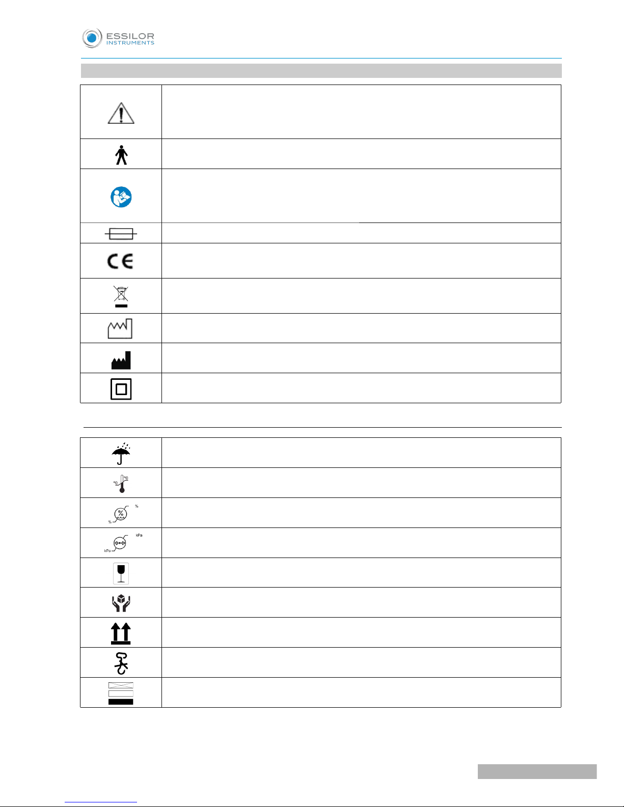
2. SYMBOLS MARKED ON THE INSTRUMENT
WARNING
Symbol to point out attention on further information written in the instruction for use of
the device
Applied parts classified as Type B in accordance with EN 60601 1 standard‐
Refer to operation manual
It means that, for safety reasons, you need to consult the instruction manual before using
the device
Fuse
"CE marking” that attests to product compliance with European Union Directive 93/42/EEC
(Medical Devices) and following amendments
Indicates the obligation to collect and separate disposal of electrical and electronic
equipment, at the end of their useful life, according to 2012/19/EU
Date of manufacturing
Manufacturer
Class II device
a. Symbols marked on the instrument's packaging
Indicates a medical device that needs to be protected from moisture
Indicates the temperature limits to which the medical device can be safely exposed
Indicates the hygrometry limits to which the medical device can be safely exposed
Indicates the air pressure limits to which the medical device can be safely exposed
Fragile
Handle with care
This side up – carton box orientation
Do not use hook for handling
Stacking limit
USER MANUAL> I. INTRODUCTION
7
Cornea550 - Corneal Topographer > V4 - 12-2017
Page 6

3. INTENDED USE AND OPERATING PROCEDURES
The Corneal Topographer CORNEA550 is an electro medical system for the detection, capturing and digital
processing of an image of the cornea, for ophthalmologic diagnosis by eye specialists.
This system is the result of a long research carried out by recognized professionals to bring new technology,
quality and design together to the highest level. An absolute innovation in the field of topography, this
device allows "live" shooting on the computer monitor. Thanks to the electronic control of operating functions
and the broad operation distance (compared to other devices of the same type), this device eliminates image
decentralisation and focusing errors, ensuring measurement accuracy and repeatability. In addition, the
reduced brightness of placido's rings makes the exam comfortable for the patient thus guaranteeing ample
pupil size.
The video keratoscope is composed of:
• Placido's disk with 24 rings
• High-resolution colour video camera (1024x960 pixel)
• Management and control software including cornea measurement (AnaEyes)
The software allows the following:
Corneal topography module
• Assisted manual acquisition
• Advanced ring editing system allowing editing edge position to guarantee proper reconstruction also
on particularly distorted surfaces
• Available maps:
◦ Sagittal curvature map
◦ Tangential curvature map
◦ Altimetry
◦ Refractive power
◦ Gaussian curvature map
• The software elaborates display pages and summaries to focus on different aspects of a patient's
diagnosis
These include:
◦ 4-map summary
◦ Single map display page
◦ Keratoconus summary
◦ Advanced altimetry and Zernike's altimetric examination
◦ Corneal wavefront examination including:
- Editable pupil corneal wavefront examination summary with map of the most common
aberrations
- Avisual quality summary with PSF, spot diagram, MTF and sight simulation for the wavefront
examined
• Autofit to find the best contact lens based on corneal altimetry, on a database with over 50,000
lenses and possibility to customize a lens on the cornea by keying in description parameters and
simulating the lens placing it in different locations or tilting it to simulate the blinking effect
• Instruments for follow-up monitoring such as:
◦ 2 or 3 element differential maps
◦ Comparison of up to 4 different maps
Cornea550 - Corneal Topographer > V4 - 12-2017
8
USER MANUAL> I. INTRODUCTION
Page 7
• A wide range of synthetic descriptors of corneal characteristics such as:
◦ Sim-K to simulate fixed ophthalmoscope measurements (for the anterior surface)
◦ Main corneal meridians in 3 mm, 5 mm and 7 mm areas
◦ The flattest and steepest hemi meridians in 3 mm, 5 mm and 7 mm areas
◦ Peripheral degrees
◦ Pupil decentralization, pupillary radius and size of the corneal diameter
◦ Keratorefractive indices calculated in the pupil area to evaluate patient's visual quality
◦ Keratoconus screening index for diagnosis and follow-up
Pupillometry module
A pupillometry module completely integrated with topography enables:
• Pupillometry with scotopic light to determine pupil maximum extension and optic zone diameters for
treatment settings
• Pupillometry with mesopic light (4 lux)
• Pupillometry with photopic light (50 lux)
• Dynamic pupillometry, starting with over 400 lux and switching off the light source so that the pupil
can dilate to its maximum extension
• Evaluation of pupil decentralization from the corneal vertex for each of the conditions previously
described and calculation of the pupil centre during dilation
• Apply the measurements previously listed to the calculation of the corneal wavefront and visualize the
pupil in different conditions on the topographic map
Videokeratoscopy module
• Examination of the tear film with white light
• Examination of the tear film with fluorescein
• Break up time measurement
• Examination of tear layers
• Examination of rigid contact lens' adaptation with fluorescein
a. Classification
Medical device classification
Device classification in accordance with the rules set out in Annex IX of Directive 93/42/EC and subsequent
amendments: Class I with measuring function.
This device is 0459 since march 2015. Its expected lifetime is 7 years.
Electromedical devices classification
• Type of protection against direct and indirect contact: Class I
• The only applied part is the headrest
• Applied parts: Type B.
• Degree of protection against humidity: common device (no protection against water seepage) IP20.
• Sterilization method: disinfectable device.
• Degree of protection when used with anaesthetics or flammable detergents: no protection.
• Conditions of use: continuous operation.
• Degree of electrical connection between the device and the patient: device with parts applied to the
patient.
USER MANUAL> I. INTRODUCTION
9
Cornea550 - Corneal Topographer > V4 - 12-2017
Page 8
b. Environmental conditions
As long as the device is kept in its original packaging, it can be exposed to the following environmental
conditions without being damaged, and for a maximum period of 15 weeks during shipping and storage:
Operation
• Temperature: +10 to +35°C
• Humidity: 30 to 90%
• Atmospheric pressure: 800 to 1060 hPa
Storage
• Temperature: -10 to +55°C
• Humidity: 10 to 95%
• Atmospheric pressure: 700 to 1060 hPa
Transportation
• Temperature: -40 to +70°C
• Humidity: 10 to 95%
• Atmospheric pressure: 500 to 1060 hPa
Vibration
• Sinewave: 10Hz to 500Hz 0.5g
• Shock 30g. Time: 6ms
• Bump 10g. Time: 6ms
c. Warranty
The manufacturer is responsible for compliance with Directive 93/42/EC as amended by 2007/47/EE, its
performance, safety and reliability, and the CE marking.
Device lifetime: 7 years, nevertheless manufacturer denies such responsibility when:
• The installation and commissioning are not made in accordance with the instructions and precautions
given in this manual
• The device is not used in accordance with the instructions and precautions in this manual
• Spare parts and accessories not supplied or recommended by manufacturer are used
• Repairs and safety checks are not carried out by competent personnel, qualified, trained and
authorized by manufacturer
• The electrical installation of the room in which the appliance is not in compliance with IEC and laws
and regulations
Manufacturer disclaims any liability for direct or indirect consequences or damages to persons or property,
resulting from improper use or incorrect clinical evaluation of its use.
Parts subject to wear and/or deterioration in normal and parts damaged by improper use or maintenance
performed by persons not authorized by manufacturer are not covered by this warranty.
To request technical assistance with maintenance, please contact directly your local technical center or your
distributor.
Cornea550 - Corneal Topographer > V4 - 12-2017
10
USER MANUAL> I. INTRODUCTION
Page 9
4. SAFETY PRECAUTIONS
• Do not touch the computer mains power cable with wet hands. Make sure the mains power cable is
not walked on or trapped under weights. Do not tie the mains power cable.
• The power source must have a differential circuit breaker (IΔn= 30 mA) and a thermal magnetic
circuit breaker (Vn=230V) to protect the device. The power socket must be close and easily
accessible.
• A damaged power cable can cause fire or electric shock. It must be checked frequently. If the
supplied computer power cable needs to be replaced, please contact the supplier.
• Do not attempt to carry out any technical intervention on the device or on the system unless specified
in this manual.
• NEver attempt to modify or disassemble the device yourself.
• Do not use the device in the proximity of water and avoid liquid spillage on any surface of the device.
Avoid humid or dusty places or places which are subject to rapid fluctuations in temperature and
humidity.
• Unplug the device from the power socket before cleaning and/or disinfecting.
• The device does not generate or receive electromagnetic interferences when operated near other
devices. No preventive or corrective action is necessary.
• No precautions are necessary in case of any changes affecting the device performance.
• In addition to the image capturing system, the device includes non electromedical appliances
(personal computer, monitor, etc.). The resulting system is in any case tested in accordance with EN
60601:1 standards. Since the unit in question can include other instruments, medical electrical or not,
manufacturer is unable to test compliance of all possible configurations.
• The configuration verified by manufacturer is the one with the personal computer outside of the
patient's area.
• Any peripheral device (printer, scanner, CD player, etc) connected to the analogical or digital interface
of the system must comply with the following standards:
◦ EN: 60950-1 for ITE equipment (safety standards for information technology equipment ) or ;
◦ EN 60601:1 for medical electrical equipment. The peripheral devices must be connected outside
of the patient's area.
• After connecting all the peripheral devices, the user is responsible for regularly verifying compliance
of the electromedical system with EN 60601:1 standards (the specific requirements are reported in
chapter 16 of the standards).
• Excessive light energy provided by infrared diodes can damage the patient's retina.
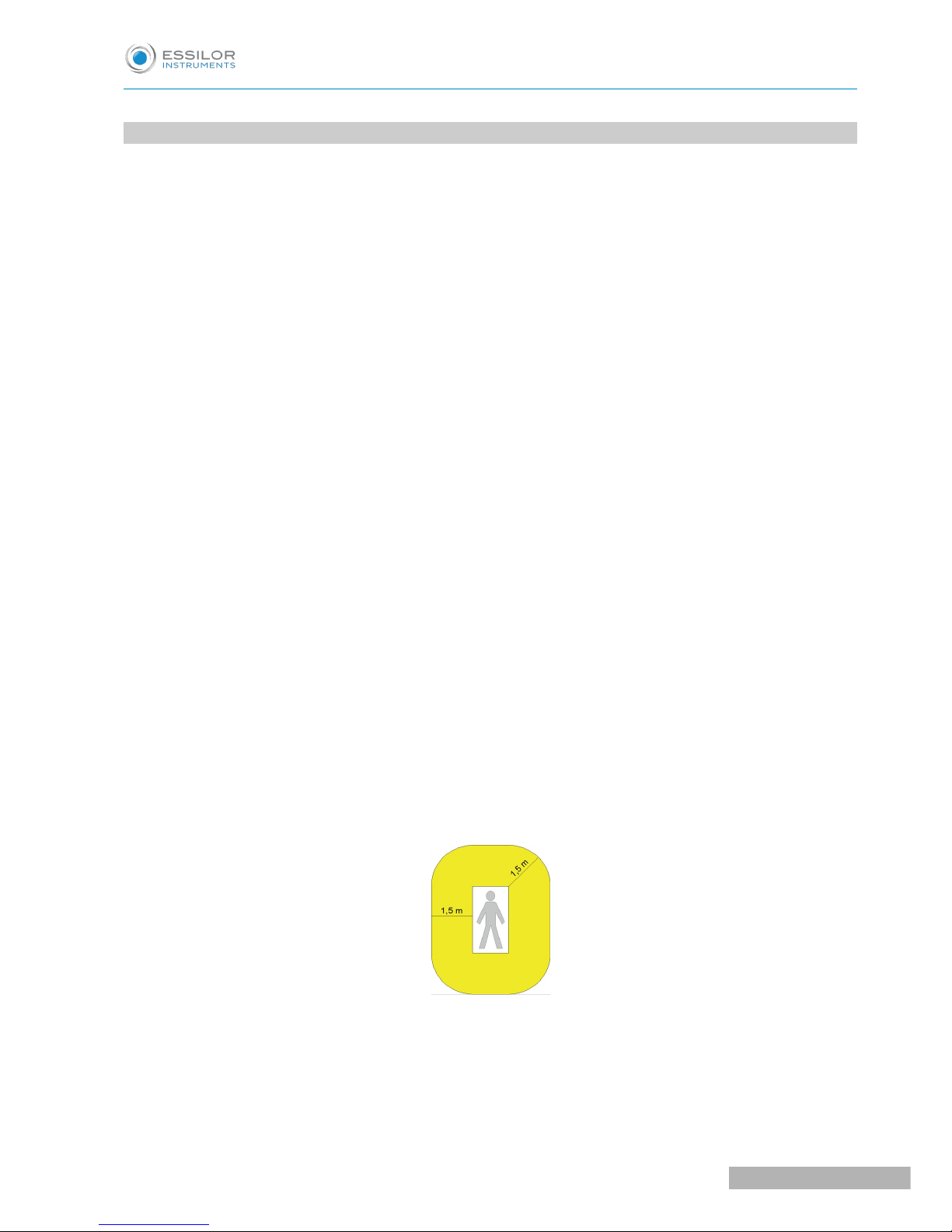
The device and all peripheral devices should be placed outside the patient area.
The patient area is the volume defined as shown in the figure, within which the patient may come into
contact (intentionally or unintentionally, directly or through contact with the operators) with medical
electrical and other devices making up the system.
USER MANUAL> I. INTRODUCTION
11
Cornea550 - Corneal Topographer > V4 - 12-2017
Page 10

• If leakage current values exceed regulatory limits, further safety measures must be adopted, as
indicated in the EN 60601:1 standards (3rd edition). In this case, the overall system must be powered
through an adequate separator or isolation transformer.
• The transformer is absolutely necessary in case the operators cannot easily keep the computer and
other non-electromedical appliances outside of the patients' area.
Warning
Only units with manufacturer trademark can be placed and used in the patient's area. The
following parts of the system must instead be placed outside the patient's area:
• Computer (desktop or laptop), with any peripheral device (monitor, keyboard, mouse,
etc.)
• Printers
• Other non-electromedical auxiliary devices (supply units/battery chargers, UPS, modem,
etc.)
If the system needs to be connected to a computer network (LAN) all the necessary measures
must be adopted to prevent transfer of dangerous voltage from remote stations, through the
connected cables. The use of data transfer devices ensuring "GALVANIC ISOLATION" may be
necessary.
Manufacturer shall not be held liable in relation to the patient and operator's safety in the case of
electrical connections between the computer and other external units (peripherals) or LAN networks
which are not made by the manufacturer itself.
5. DISPOSAL AT THE END OF LIFE
According to directives 2012/19/UE WEEE and 2011/65/UE RoHS II on the restriction of hazardous
substances in electrical and electronic equipment and on their disposal.
Public authorities adopt adequate measures to make sure that users, distributors and manufacturers
contribute to the collection of electrical and electronic equipment, setting legal requirements for reusing,
recovering or recycling said equipment.
The device purchased has been manufactured using special materials and substances. The device may
contain hazardous substances potentially harmful to the environment or to human health if improperly
disposed of into the environment.
Cornea550 - Corneal Topographer > V4 - 12-2017
12
USER MANUAL> I. INTRODUCTION
Page 11

Warning
The user must take into account the potentially harmful effects to the environment or human
health due the improper disposal of the equipment or of parts of it.
To prevent the release of hazardous substances into the environment and to promote conservation of natural
resources, the manufacturer, in case the user wishes to dispose of the device used at the end of its useful
life, facilitates the possibility of its reuse and the recovery and recycling of the materials contained therein.
The graphic symbol shown in the figure is applied on the equipment's label.
It reminds that all electrical and electronic equipment must be collected and disposed of
separately at their end-of-life.
In the case of disposal of the device, specific provisions of European and national law apply, and provide
that:
• The device shall not be disposed of as urban waste, it shall be collected separately, by contacting a
company specializing in the disposal of electrical/electronic equipment or the public authorities
responsible for waste management.
• In the event that a new piece of equipment is purchased from the same manufacturer to replace an
old one placed on the market before 13 August 2005, equivalent and with the same functions of the
new equipment, the distributor or manufacturer is legally required to collect the old piece of
equipment.
• If the user wants to get rid of a used piece of equipment, placed on the market after 13 August 2005,
the distributor or manufacturer is legally required to collect it.
• By joining the specific technological waste disposal consortium, the manufacturer shall take care of
the handling, recovery and/or disposal of the old equipment collected, at its own charge.
The manufacturer will provide the users with any information regarding the hazardous substances contained
in the device and on the recovery and recycling of said substances, as well as on the possible reuse of the
used device.
Violations shall be punished by the current legislation with serious administrative sanctions.
USER MANUAL> I. INTRODUCTION
13
Cornea550 - Corneal Topographer > V4 - 12-2017
Page 12

II. SUPPLY PACKAGE
Page 13

The system is composed of the following main units:
Topographic unit, designed and manufactured by ESSILOR, composed of:
1. Keratoscope
2. External power supply unit:
◦ INPUT : 100-240Vac 50/60Hz 0,9A
◦ OUTPUT : 24Vdc - 2A
3. AnaEyes software
The system is supplied with the following accessories:
• Two guards for the slide guides
• One protection cover
• One set of Allen wrenches
• One set of chinrest papers
• Two fuses
• One calibration set
• Chinrest
Optional
• Table top
• Elevating lift
• Sliding kit for table top
• Computer
Cornea550 - Corneal Topographer > V4 - 12-2017
16
USER MANUAL> II. SUPPLY PACKAGE
Page 14
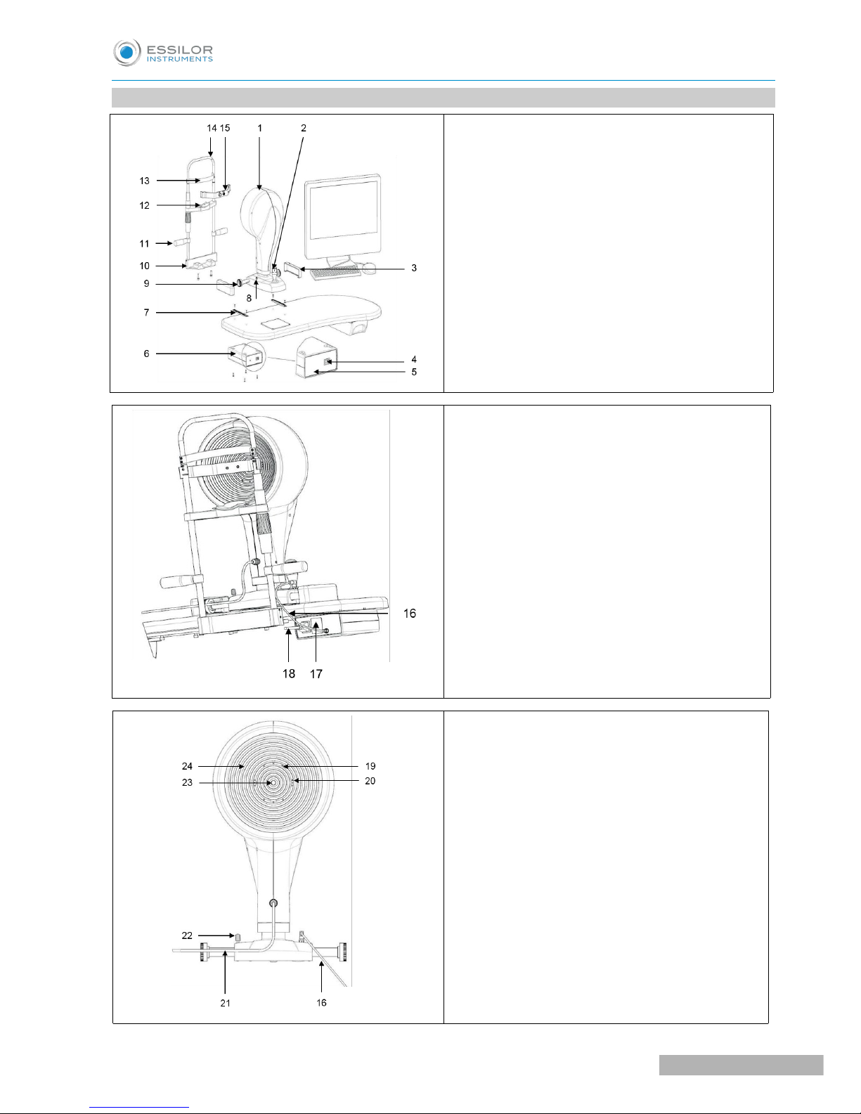
1. PARTS IDENTIFICATION
1. Instrument with Placido's disk
2. Joystick with capturing trigger button
3. Guiding slides guards
4. Optical switching switch
5. Power lamp
6. Optical switching
7. Geared guides
8. Output
9. Geared wheels
10.Chinrest support
11.Patient's handle
12.Chinrest
13.Headrest
14.Chinrest module
15.Calibration set
16. Instrument power supply cable
17. Optical switching data nameplate
18. Mains supply cable
19. IR LED
20. Blue LED
21. USB3 cable
22. Locking knob
23. Capturing channel
24. Placido's disk
USER MANUAL> II. SUPPLY PACKAGE
17
Cornea550 - Corneal Topographer > V4 - 12-2017
Page 15

III. ROUTINE MAINTENANCE
Page 16

The system does not require any particular routine maintenance operations by the user. To clean the
external surfaces simply use a cloth slightly dampened with water.
Use the paper to cover the chinrest after each patient use.
Protection against dust
When not in use, protect the system against dust. Dust accumulating on the device must be regularly
removed with a soft cloth or blower.
Other maintenance operations (repairs, components replacement, assessment of internal components, etc.)
fall within the exclusive competence of the manufacturer technical assistance service.
Warning
Do not use any thinners or solvents.
If the product needs maintenance, contact the technical service authorized by the
manufacturer.
Cornea550 - Corneal Topographer > V4 - 12-2017
20
USER MANUAL> III. ROUTINE MAINTENANCE
Page 17

IV. USAGE
Page 18

The user has evaluation criteria based on his experience that allows him to critically analyze the software.
Keratoscopy
Have the patient comfortably sit down with his/her chin on the chinrest and the forehead against the
forehead rest.
Lift and lower the chinrest using the handle to align the patient's eyes with the central eyepiece of the
instrument.
Enter the AnaEyes software.
To use the corneal topographer follow the main instructions below:
• Press the "NEW PATIENT" button and key in "FIRST NAME" and "LAST NAME" (if the patient is
already in the database you can launch an automatic query by last or fictive name).
• Key in the "BIRTHDATE" and click "SAVE".
• Key in the "BIRTHDATE" (these data are compulsory and required by the management software).
• Choose the exam mode among "KERATOSCOPY", "VIDEOKERATOSCOPY", "PUPILLOGRAPHY",
"MEIBOGRAPHY", "TEAR FILM".
Move onto the instrument.
Move the joystick to centre the eye on the display, refocus placing the joystick perpendicular to the table.
Now pull the joystick completely back towards you, then press and hold the button while pushing the
joystick towards the patient.
The capturing will be automatically completed with a focused image.
More images are captured consecutively.
Select the images to preview.
Double-click on each individual image to save the best images.
Exit the capturing window to save the images to the gallery.
Double-click on the selected image in the gallery to enter the image processing environment.
If necessary, edit the rings in the ring editing menu.
If necessary, edit the pupil size in the pupil editing menu.
If necessary, edit the limbus size in the limbus editing menu.
>
>
1
2
3
4
5
6
7
8
Cornea550 - Corneal Topographer > V4 - 12-2017
22
USER MANUAL> IV. USAGE
Page 19

Click "OK" to save any changes made.
At this point, the exam is complete.
Please refer to the software user manual for videokeratoscopy, pupillography, meibography, tear film
modes.
For further information and access to all image elaborations, please refer to the user manual of
AnaEyes.
Warning
• To avoid the risk of electric shock this device must only be connected to a power supply
system with protective earthing.
• For isolation from the mains (condition of complete safety) the computer power cable
must be disconnected.
• To turn off the system, simply follow the usual procedure to exit the software, then switch
off the computer power switch.
• Do not switch off the computer or disconnect the cable between the computer and the
topographer when the program is running.
>
9
USER MANUAL> IV. USAGE
23
Cornea550 - Corneal Topographer > V4 - 12-2017
Page 20

V. TECHNICAL FEATURES
Page 21

Operation distance 74 mm from corneal vertex
Number of rings 24
Number of measuring points 6144 (24x256)
Number of points analyzed Over 100000
Diameter of the corneal area covered (at 43 D) 0.4 to over 9.6 mm of diameter
Dioptres measuring arc 1 to 100 D
Accuracy and repeatability error Class "A" as per "ISO19980"
Power supply Through 24V DC external power supply unit
Input power supply unit specifications
INPUT : 100-240Vac 50/60Hz 0,9A
OUTPUT : 24Vdc - 2A
Power cable technical specifications
Four-core cable (three cores with earth),
conductors minimum cross-section 1mm²
Placido's LED lighting White LED
Fluorescein LED lighting Blue LED 460 nm
Pupillometry LED lighting IR LED 875 nm
Weight 6.2 kg
Size ( HxWxD) mm 505x315x251 mm
Computer connection USB3 Type A cable
Cornea550 - Corneal Topographer > V4 - 12-2017
26
USER MANUAL> V. TECHNICAL FEATURES
Page 22

VI. GUIDANCE AND MANUFACTURER'S
DECLARATION
Page 23

1. ELECTROMAGNETIC EMISSION
Guidance and manufacturer's declaration – electromagnetic emission
The equipment CORNEA550 is intended for use in the electromagnetic environment specified below.
The customer or the end user of the CORNEA550 should assure that it is used in such an environment.
Emission test Compliance Electromagnetic environment - guidance
RF emission – CISPR 11 Group 1
The CORNEA550 uses RF energy only for its
internal function. Therefore its emissions are
very low and are not likely to cause any
interference in nearby electronic equipment.
RF emission – CISPR 11 Class B The CORNEA550 is suitable for use in all
establishments including domestic
establishments and those directly connected to
the public low voltage power supply network that
supplies buildings used for domestic purposes.
Harmonic emission
IEC 61000-3-2
Class A
Voltage fluctuation/flicker emission
IEC 61000-3-3
Complies
Cornea550 - Corneal Topographer > V4 - 12-2017
28
USER MANUAL> VI. GUIDANCE AND MANUFACTURER'S DECLARATION
Page 24

2. ELECTROMAGNETIC IMMUNITY
Guidance and manufacturer's declaration – electromagnetic immunity
The equipment CORNEA550 is intended for use in the electromagnetic environment specified below. The
customer or the end user of the CORNEA550 should assure that it is used in such an environment.
Immunity test
IEC 60601
Test level
Compliance level
Electromagnetic environment -
guidance
Electrostatic discharge
(ESD) IEC 61000-4-2
±6 kV contact
±8 kV air
±6 kV contact
±8 kV air
Floors should be wood, concrete or
ceramic tile. If floors are covered with
synthetic material, the relative humidity
should be at least 30%.
Electrical Fast
Transient/burst IEC
61000-4-4
±2 kV for power
supply lines
±1 kV for I/O lines
±2 kV for power
supply lines
Not applicable
Mains power quality should be that of a
typical commercial or hospital
environment.
Surge
IEC 61000-4-5
±1 kV differential
mode
±2 kV common
mode
±1 kV differential
mode
±2 kV common
mode
Voltage dips, Short
interruptions
and voltage variations
on power supply input
lines IEC 61000-4-11
<5% UT for 0,5
cycle
40% UT for 5 cycles
70% UT for 25
cycles
<5% UT for 5 sec
<5% UT for 0,5
cycle
40% UT for 5 cycles
70% UT for 25
cycles
<5% UT for 5 sec
Mains power quality should be that of a
typical commercial or hospital
environment.
If the user of the CORNEA550 requires
continued operation during power mains
interruptions, it is recommended that the
CORNEA550 be powered from an
uninterruptible power ssupply or battery.
Power frequency
(50/60Hz) magnetic
field IEC 61000-4-8
3 A/m 3 A/m
Power frequency magnetic fields should
be at levels characteristic of a typical
location in a typical commercial or
hospital environment.
Note: UT is the AC mains voltage prior to application of the test level.
USER MANUAL> VI. GUIDANCE AND MANUFACTURER'S DECLARATION
29
Cornea550 - Corneal Topographer > V4 - 12-2017
Page 25

Guidance and manufacturer's declaration – electromagnetic immunity
The equipment CORNEA550 is intended for use in the electromagnetic environment specified below. The
customer or the end user of the CORNEA550 should assure that it is used in such an environment.
Immunity test
IEC 60601
Test level
Compliance level
Electromagnetic environment -
guidance
Conducted RF
IEC
61000-4- 6
Radiated RF
IEC 61000-4- 3
3 Vrms
150KHz to 80MHz
3V/m
80 MHz to 2,5 GHz
3 Vrms
3 V/m
Portable and mobile RF communication
equipment should not be used close to
any part of the CORNEA550, including
cables. Recommended separation
distance. d=1,167*√(P)
d=1,167*√(P) 80 MHz to 800 MHz
d=2,333*√(P) 800 MHz to 2,5 GHz
Where P is the maximum output power
rating of the transmitter in watts (W)
according to the transmitter manufacturer
and (d) is the recommended separation
distance in metres (m).
Field strengths from fixed RF transmitters,
as determined by an electromagnetic site
survey, should be less than the
compliance level in each frequency range.
Interference may occur in the vicinity of
equipment marked with the following
symbol:
Note 1: at 80 MHz and 800 MHz, the higher frequency range applies.
Note 2: These guidelines may not apply in all situations. Electromagnetic propagation is affected by
absorption and reflection from structures, objects and people.
Cornea550 - Corneal Topographer > V4 - 12-2017
30
USER MANUAL> VI. GUIDANCE AND MANUFACTURER'S DECLARATION
Page 26

VII. APPENDIX
Page 27

All equipment composing the system is always delivered packaged in optimal conditions to withstand
standard transport and storage conditions. In the event that, when removing the device from its packaging,
damages due to transport are detected, please contact the installer company or the manufacturer directly.
• Make sure the mains voltage matches the voltage indicated on the AC/DC adapter and on the
computer. If the voltage does not match contact the technical service or the manufacturer.
• Do not use multiple sockets, adapters or extension cables to connect the device plug to the mains
socket.
• To disconnect from the power supply, also in case of emergency, grab the plug of the power cable. Do
not pull the power cable to unplug the device.
To assemble the device, follow the instructions below:
1. Secure the table top to a base. The instrument holder table is below the device ready for assembly
proceed as follows:
◦ Position the table on the base plate and insert the screws supplied.
◦ Fix the top to the bottom by tightening the four socket head screws.
2. Unscrew the two socket head screws under the chinrest.
◦ Insert the screws in the chinrest module and align its holes with the holes of the table top.
◦ Tighten the screws with the wrench provided with the device.
3. Place the base with orthogonal movements on the slides on top of the instrument holder table.
◦ Make sure the wheels are aligned.
◦ Lock the device with the knob (22) on the right side of the base, above the wheels axis.
4. Fix the guards (3) along the slides by inserting the tags into their slots.
5. Connect the computer to the mains and switch on the computer.
6. If the AnaEyes software is not already installed, follow the instructions on the user manual supplied
with the software to install it.
7. Make the following connections:
◦ Connect the power supply unit to the mains with the cable (18).
◦ Plug in the device power supply cable (16).
8. Turn on the power supply unit.
9. Connect the USB cable (21) to the computer.
10.The system is ready for use.
Cornea550 - Corneal Topographer > V4 - 12-2017
32
USER MANUAL> VII. APPENDIX
Page 28

USER MANUAL> VII. APPENDIX
33
Cornea550 - Corneal Topographer > V4 - 12-2017
Page 29

Essilor Instruments USA
8600 W. Catalpa Avenue, Suite 703
Chicago, IL 60656
Phone: 855.393.4647
Email: info@essilorinstrumentsusa.com
www.essilorinstrumentsusa.com
 Loading...