

Page 1

User Guide
Auto Lensmeter ALM 700
Version 2
April 2015
UMALM700
Page 2

Page 3

Introduction
This device is aims to measure S, C, A, prism refractive power, UV transmission and PD of the
framed lens and contact lens.
About This Manual
Please read this manual thoroughly so that safe and effective operation is ensured.
(1) The information contained in this manual is subject to change without notice.
(2) While reasonable efforts have been made in the preparation of this document to ensure its
accuracy, you should contact your local distributor immediately if any queries arise due to
editorial errors or omissions etc.
(3) If finding any imperfect collating or missing pages, contact your local distributor for
replacement.
This manual contains important contents to prevent users or others from harms and to use this
device safely.
Read this manual after understanding the symbols below and follow the instructions in use.
This symbol indicates that mishandling as a result of failure to
Warning
NOTE
comply with the indications can result in “personal death” or
“serious injury”.
Denote general ban or prohibition.
General mandatory action.
Additional information which is important to the text or useful/
convenient to know.
The number on the left is the lower limit and the one on the right is
the upper limit of the temperature.
The number on the left is the lower limit and the one on the right is
the upper limit of the humidity.
Avoid direct sunlight.
1
Page 4

this product complies with applicable CE directives.
This manual contains the information about basic operation, inspection and
maintenance etc. of ALM700.
Manufacturer
Electrical and Electronical Waste – please contact your
distributor to recycle this product
2
Page 5

Safety Consideration
General Cautions
It affects its measurement accuracy if fingerprints or dust etc. are on the optical components such
as glass parts under the lens stand.
Do not touch them with hands, and avoid dust.
If fingerprints or dust are adhered on the optical parts such as a lens etc., wipe it gently with
a soft cloth.
Observe the following environmental conditions for use, storage and transportation.
Avoid installation near TV or radio. The reception can be disturbed by electrical noise.
If liquid is spilled on this device or a foreign substance is entered in it, unplug the power cord and
contact your local distributor.
Turn off the power immediately and contact your local distributor if malfunction (noise, smoke
etc.) occurs. It can result in fire or injury if you keep using it.
Do not attempt to disassemble it. It can result in malfunction or fire.
If malfunction occurs, do not touch the inside of this device. Unplug the power cord and contact
Use
Storage
Transportation
No Dew Condensation
your local distributor.
In case of disposal, comply with the regulations and recycle plan of the local government.
Inappropriate disposal causes a negative effect on environment.
3
Page 6

Contents
Introduction.......................................................................................................................................1
About This Manual ...........................................................................................................................1
Safety Consideration.........................................................................................................................3
1. Accessories.....................................................................................................................................6
2. Device.............................................................................................................................................7
2.1 General Descritpion of Device.................................................................................................7
2.2 Parts Identification..................................................................................................................7
3. Instructions for Use.......................................................................................................................9
3.1 Installation...............................................................................................................................9
3.2 Connection/ Wiring................................................................................................................10
3.3 Maintenance/ Inspection .......................................................................................................10
3.4 Disposal..................................................................................................................................11
4. Measurement Screen...................................................................................................................12
4.1 Description of Measurement Screen.....................................................................................12
4.2 Preparation for Measurement...............................................................................................13
4.2.1 Device Setting .................................................................................................................13
4.2.2 Setup (Device Setting) Screen ........................................................................................13
4.2.3 ID Screen .........................................................................................................................15
4.2.4 Data Output Screen ........................................................................................................16
4.2.5 Data/Time Screen............................................................................................................17
4.2.6 Default Setting Screen....................................................................................................17
5. Operating Instructions of Device...............................................................................................
5.1 Lens Holder............................................................................................................................18
5.2 Lens Plate ..............................................................................................................................18
5.3 Marking Lever .......................................................................................................................19
5.3.1 Operating Instructions....................................................................................................19
5.3.2 Replacement of Marking Pen .........................................................................................20
5.4 Printer....................................................................................................................................21
5.4.1 Operating Instructions....................................................................................................21
5.4.2 Installation and Replacement of Printer Paper.............................................................22
5.5 Replacement of Fuse..............................................................................................................23
6. Measurement...............................................................................................................................24
6.1 Checkup before Measurement ..............................................................................................24
6.2 Measurement of Single Lens.................................................................................................25
6.3 Measurement of Framed Lens ..............................................................................................26
6.4 Pupillary Distance (PD) Measurement.................................................................................27
6.4.1 Device Setting .................................................................................................................27
6.4.2 Measurement Procedure.................................................................................................27
6.5 Measurement of Multifocal Lens ..........................................................................................28
6.6 Measurement of Progressive Lens........................................................................................29
6.7 Measurement of Ultraviolet (UV) Transmission..................................................................32
6.7.1 Device Setting .................................................................................................................32
6.7.2 Measurement of UV Transmission after Measuring Degree……………… .... ……… 32
6.8 Measurement of Contact Lens ..............................................................................................33
6.8.1 Preparation......................................................................................................................33
.18
4
Page 7

6.8.2 Measurement Procedure.................................................................................................33
7. Marking .......................................................................................................................................34
7.1 Lens without Astigmatism....................................................................................................34
7.2 Lens with Astigmatism .........................................................................................................34
7.3 Marking of Prism Lens..........................................................................................................35
8. Other Functions ..........................................................................................................................36
8.1 Auto Memory Function..........................................................................................................36
8.1.1 Operation Procedure.......................................................................................................36
8.2 Power Saving Function .........................................................................................................37
9. Error Display...............................................................................................................................38
9.1 Type........................................................................................................................................38
9.2 Error Handling Procedure.....................................................................................................39
10. Storage of Device.......................................................................................................................40
11. Specification...............................................................................................................................41
12. EMC (Electromagnetic compatibility) 42
5
Page 8

1. Accessories
Power cord: 1
(2.5m)
Dust cover: 1 Contact lens stand: 1
Use the accessories specified by us.
The printer paper is the thermal paper roll.
Avoid direct sunlight, high humidity and high temperature at the time of storage.
Printer paper: 1
(Width: 58mm)
Operation manual: 1
6
Page 9
2. Device
2.1 General Descritpion of Device
This device aims to take the measurements of SPH, CYL, AXIS, prism refractive power and
optical axis coordinate of unprocessed lens, processed framed lens and contact lens, and to
put dots on them to find its axis.
As an external feature, the angle of the LCD can be changed.
Refer to “3. Instructions for Use” about the operating precautions of this device.
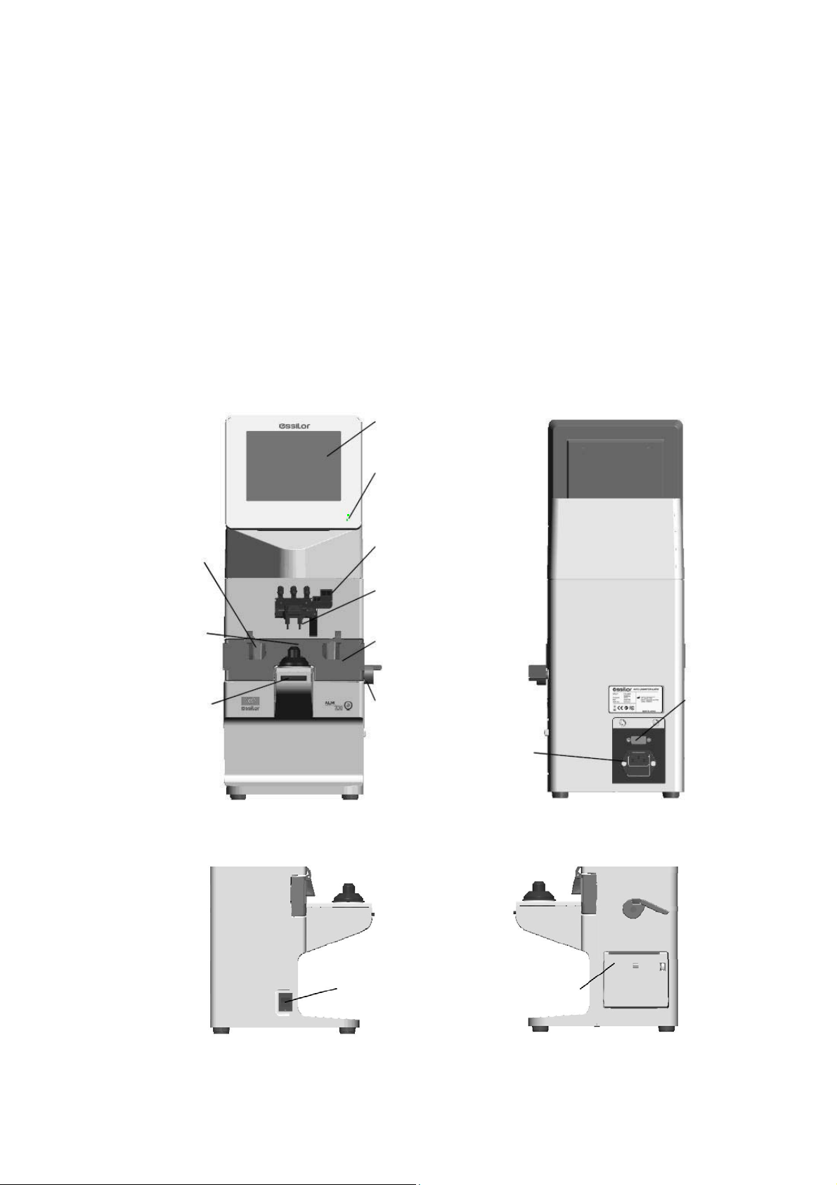
2.2 Parts Identification
Nose pad
Lens stand
Memory/Add
switch
LCD (with
touch panel)
Pilot lamp
Marking lever
Lens holder
Lens plate
Lens plate lever
Power inlet
(with fuse holder)
Communication
connector
Power switch
7
Printer
Page 10

LCD
Color LCD with 640 X 480 dots
User-friendly LCD which is adjustable vertically within operating range (60°)
Touch panel is adopted.
Pilot lamp
Lamp to indicate ON (light on)/ OFF (light off) and power saving mode (blink)
Marking lever/ lens holder
The marking lever and lens holder are integrated.
・Marking lever: puts the dots by pressing the lever down.
・Lens holder: fixes the framed glass on the lens stand by moving the lever up and down.
Lens stand
Take a measurement by placing the framed lens on the lens stand.
Lens plate
The plate to be reference of the cylindrical axis and specified direction of the prism.
For the framed lens, take a measurement so as that the lens frame contacts with the lens plate.
Lens plate lever
Moves the lens plate back and forth
Nose pad
Used for measuring PD of the framed lens.
Set the framed lens so as that the nose pad is placed on it. The judgment of right and left and PD
measurement are performed based on the position of the nose pad.
Memory/Add switch
The switch to store the measurement values on the measurement screen of single focus lens,
multifocal lens and contact lens.
Freezes the display of the measurement values and store them.
The switch to execute the near and far points in case of manual measurement on the progressive
lens measurement screen
Communication connector
The communication connector to transfer the measurement data to the other devices and
computers.
Power inlet
The inlet to connect the power cord supplied to supply power.
Power supply switch
The switch to turn on/ off the power of the device
Printer
Prints out the measurement values
8
Page 11

3. Instructions for Use
3.1 Installation
(1) Do not expose the device to sunlight or bright light from lighting
equipments.
NOTE
Do not install the device in places where either dust or rubbish may
Take extra caution to avoid strong light because
it may cause the failure of measurement.
accumulate.
Also, the environments with extremes in heat and
humidity should be avoided.
In case of using the device, ensure to comply with the
environmental conditions of unpacking and usage before
starting a measurement.
・Temperature range for use: 5 to 40
・Humidity range for use: 30%HR to 95%HR
・Temperature range for storage: -10 to 55 (No dew condensation)
・Humidity range for storage: 10%HR to 95%HR (No dew condensation)
(2) Keep away from inflammable or explosive gases as
well as storage area of the medical supplies and
chemicals.
(3) Keep away from the sites that experience strong
vibrations or sudden shocks.
Dust
Gas
(4) The device might be broken if it falls down. Also,
it might cause injury if dropping it. Therefore, do
not store it at an unstable place or in high, ‘out of
reach’ place.
(5) Keep this device away from water (liquid).
・Degree of protection: IP20
9
Page 12

3.2 Connection/ Wiring
(1) The earth cable of the power code should be connected to the earth terminal.
(2) Avoid damaging the power cord (such as bending it in an extremely small size, pulling,
placing a heavy object on it etc.). Also, do not fabricate the cord.
(3) When the power cord is damaged, (breaks, damage of cover etc.), replace it to the new one.
Fire or electric shock may occur if you keep using it.
(4) Insert the power cord firmly into the outlet and device. If not, fire or electric shock may occur.
(5) Keep the power cord clean without any dust or oil etc. on it. The dirty terminal may cause
malfunction or fire.
(6) When the power cord gets hot after use, check for the dirt of the terminal unit. If you find no
dirt, replace the power cord to the new one. Fire or electric shock may occur if you keep
using it.
(7) Use it with the correct power-supply voltage. Fire or electric shock may occur if using it with
more than the rated supply voltage.
(8) Always hold the plug when plugging or unplugging the power cord.
(9) Do not touch the plug with wet hands. You may get an electric shock.
(10) If the device is not used for a long time, unplug the power cord from the outlet.
3.3 Maintenance/ Inspection
(1) This is the precision optical device. Make sure not to mishandle
or drop it.
(2) Do not touch or allow dust to adhere on the optical parts
(i.e. lenses), as the measurement accuracy could be adversely
affected by fingerprints and dust etc.
When fingerprints or dust are adhered onto the optical parts,
gently wipe them with the accompanying dust cloth or a soft
cloth. In this instance, make sure not to scratch them.
10
Page 13

(3) If the main unit cover or operation panel is dirty, gently wipe it
with a dry cloth. For hard to remove stains, a damp cloth or
neutral cleanser is recommended.
(4) If the device is not used for any length of time, unplug
the power cord.
When the device is not in use, protect it with the
accompanying dustproof cover. The measurement
accuracy could be affected by dust.
(5) Never attempt to fix or remodel the device. When the
device fails to function properly, do not touch the inside.
Contact us or your local distributor.
Avoid using organic solvent such as thinner
which may damage the water based paint
finish or device.
3.4 Disposal
In case of disposal, comply with the regulations and recycle plan of the local government.
Inappropriate disposal causes a negative effect on environment.
11
Page 14

4. Measurement Screen
A
4.1 Description of Measurement Screen
Measurement setting
Type of lens: left/
right/ single
XIS mark
-3
Display of alignment
condition or error
message
Cross cursor
Measurement screen of single focus lens, multifocal lens and contact lens
※ The display of the measurement screen reflects the setting and condition of the device.
The touch panel is adopted. They are corresponding to the icons on the monitor.
【Explanation about switches】
Name of icon Icon Description of function
Bottom of monitor: 5
Device setting
Switch of
measurement
Switch to the Setup (device setting)
screen.
Switches to multifocal lens
measurement from single focus lens.
Unprocessed lens/
framed lens
selection switch
Clear
Measurement
value output
Lens stand unit: 1
Memory/Add
switch
No icon
Selects unprocessed, left or right lens.
Deletes measurement values stored in
memory.
Prints out measurement result, outputs
data from RS232C or both.
Stores measurement values in memory
and take a measurement of ADD.
12
Page 15

4.2 Preparation for Measurement
4.2.1 Device Setting
This device is ready for use with the standard mode but the setting can be changed easily
as needed.
Switch to the Setup (setup of device) screen by touching
of screen.
Change of switch function
The functions of each switch are changed on the menu screen.
The icons are displayed on the screen. Touch the icon in accordance with the display.
NOTE
:Moves the cursor downward at each setting item
:Moves the cursor upward at each setting item
:Goes to a further page of Setup. ( → → → )
:Selects the item of each setting item. The selection cursor moves vertically.
:Switches back to the measurement screen.
4.2.2 Setup (Device Setting) Screen
【1/4 screen】
at the bottom
Item Description of Function
Cyl Selects sign for Cyl:- / + / ±
Step
Prog.
Lens
Memory
ADD
Measure
PD
Measure
Selects step to display measurement value
0.25 / 0.12 / 0.01
Sets auto detection of progressive lens Auto
On / Off
Selects lens to be measured
Normal: Framed lens
H CL: Hard contact lens
S CL: Soft contact lens
Sets auto memory at the time of “Marking OK” Auto
On / Off
Selects auto/ manual memory of far and near
points
F/N.AT: Stores both near and far points
automatically
N.AT: Stores only near point automatically
Manual: Stores data manually
Selects if performing PD measurement or not
On: Perform / Off: Not perform
13
Page 16

【2/4 screen】
Item Description of Function
UV
Measure
UV
Graph
Prog.
Graph
Graph
Print
Prism
Prism
(mm)
Abbe
Selects if performing UV transmission
measurement or not
On:Perform / Off: Not perform
Selects if displaying UV transmission
graph or not
(displayed only on the progressive lens
measurement screen)
On:Perform / Off: Not perform
Selects if displaying the assessment graph
or not
On:Display / Not display
Selects if printing out the assessment
graph after measuring progressive lens
On: Print out / Off: Not print out
Selects if displaying prism or not, and
selects the unit to be displayed
Off: Not display X-Y:X-Y display
P-B: Prism value – base direction
Select if displaying prism value of X-Y
direction in mm
On: Display / Off: Not display
Selects Abbe number : 20 / 30 / 40 / 50 / 60
【3/4 screen】
Item Description of Function
Ray
Standby
Language
Brightness
Sound Mute
ID
Data Output
Selects measurement wavelength
e-line / d-line
Selects time to activate standby mode
Off / 3 min. / 5min. / 10min.
Selects language displayed on screen
English, French, Spanish, Italian,
Portuguese, German, Chinese
Sets brightness of screen
(50% to 100%)
Sets On/ Off of buzzer at the time of
operating switches
Switches to ID screen
Switches to Data Output screen
14
Page 17

【4/4 screen】
4.2.3 ID Screen
This screen is to create the data for printing out the distributor’s name or message on
the printout.
(1)
Item Description of Function
Date/Time
Switches to Date/Time screen
Displays the Setup items
Default
Setting
changed from default and
changes the setting back to the
default by pressing
The screen shown on the left appears by
selecting “ID Screen”.
(1) is the screen for writing the information.
(2) is the screen for changing or erasing the
information.
How to input
.
The cursor in moves by pressing
the arrows.
(2) While Memory/Add switch is held
The cursor in moves while the
Memory/ADD switch is held
In the Screen (1), select the characters with
and enter them with
. Any changes made will overwrite the
original characters.
The maximum number of characters is
44 (22 characters X 2 lines).
In case of changing the characters, move the
cursor to the one changed by pressing
with holding the
Memory/Add switch. Return to Screen (1) and
select the character to be input with
and press .
How to delete
In case of deleting the characters, move the
cursor to the one deleted with
15
and press .
Page 18

4.2.4 Data Output Screen
This screen is to set the communication parameter for outputting the measurement values to the
externally-connected PC etc.
The measurement values and data created on the “ID Screen” are output by selecting “RS232C” or
“Both” of “Data Output” on the Setup screen.
NOTE
The output content is same with the one of the printout.
However, the graph at the time of progressive lens measurement is not output.
Communication setting to PC etc.
The communication from RS232C port is set on “Data Output”.
【Setting screen in case of outputting from RS232C】
Item Description
Setting of output destination
Output Device
Display on
measurement screen
Print RS232C Both
Device
printer
RS232C
terminal
Setting
“Off” “On”
Auto Comm
Band Rate
(communication
speed)
Output by touching
the measurement
screen output icon
Measurement values
are output
continuously
Select from 115200, 38400 or 9600.
In case of output from RS232C, the data is output only in English regardless of language
NOTE
setting.
【Example of connection】
D-Sub: 9Pin
(male)
D-Sub 9pin
Lensmete
(male)
Connection
D-Sub 9pin
(female)
PC
D-Sub: 9Pin (female)
Use the straight cable (D-sub 9 pin: male/ D-sub 9: female) as the connection cable at the
time of outputting the measurement values by using the RS232C.
※ Contact your local distributor if you have anything unclear or any questions regarding
operation and connection.
Use a shield wire for a connecting cable to protect the output data from noise.
NOTE
Both
16
Page 19

4.2.5 Data/Time Screen
The screen to set the date and time for printout and communication output
(1)
Select the item to be changed with
and set the detail with .
“Date Form”:YMD → Year, Month, Day
“Date Form”:DMY → Day, Month, Year
“Date Form”:MDY → Month, Day, Year
The setting can be also changed by touching the
screen.
(2) While Memory/Add is pressed
4.2.6 Default Setting Screen
Date: change of date
Select “Date” with
Move the cursor to the item to be changed with
.
While the Memory/Add switch is held, the Screen
(2) is displayed. Make changes with
.
Time: change of time
Select “Time” with
Move the cursor to the item to be changed with
.
While Memory/Add switch is pressed, the Screen
(2) is displayed. Make changes with
.
.
.
The screen to change the setting of the device back to the default
Touc h P res s
setting back to the default.
Press
setting back to the default. It goes back to the
measurement screen by selecting it.
17
if you do not wish to change the
if you wish to change the
Page 20

5. Operating Instructions of Device
5.1 Lens Holder
(1)
(1) Raise the lever to the operational
direction until it is unlocked.
(2) Lower the lens holder slowly and fix
the lens.
Do not give strong impact to a lens when lowering the lens holder.
When rising the lens holder, make sure to move to the top.
Operational
direction
(2)
5.2 Lens Plate
The lens plate is the reference of the cylindrical axis.
Place the framed lens and rotate the lens plate lever to the direction of the arrow so that the
bottom of the lens touches the lens plate. After that, lower the lens holder and fix the lens.
Lens plate
Lens plate lever
18
Page 21

5.3 Marking Lever
5.3.1 Operating Instructions
(1) Turn and lower the marking lever.
(2) Place the tips of the marking pens on the lens
surface softly.
Do not mark several times at the same point.
The marking pen may be worn out quickly.
(3) Release the finger after marking.
(4) The marking lever returns to the initial position.
Marking lever
Avoid the followings since they may damage the tips of the marking pens.
・ Perform marking roughly
・ Operate the marking lever without a lens set.
・ Touch a tip of the marking pen during cleaning.
19
Page 22
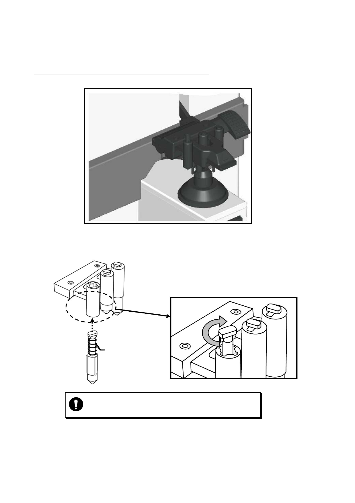
5.3.2 Replacement of Marking Pen
The marking pen is the consumable item.
Replace it if the imprint becomes thin or the pen tip is worn.
(1) Remove the marking pen by pressing and rotating it 90 degrees as shown below.
(2) Insert the new pen back to the initial position as shown below.
Insert the marking pen, and fix it by rotating
90 degrees.
Marking pen
・Ensure to use the marking pen specified for “ALM700”.
・Do not touch the pen tip at the time of replacement.
20
Page 23
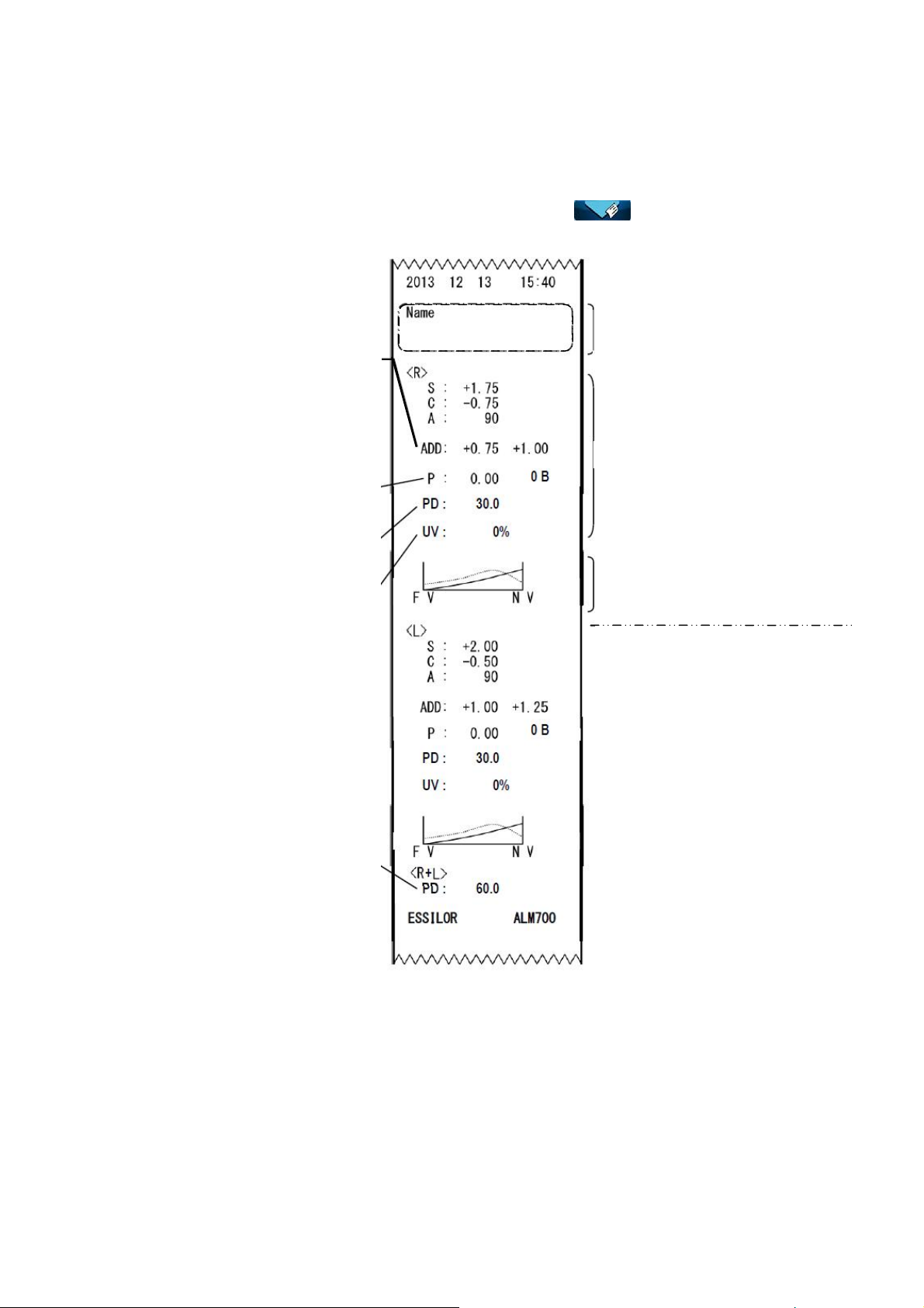
A
5.4 Printer
5.4.1 Operating Instructions
The measurement values can be printed out by touching after taking
a measurements.
dd measurement values are
displayed only at the time of
measurements of multifocal
lens and progressive lens
(Left: ADD1, Right: ADD2)
The unit of the prism value
is different according to the
setting.
PD of right eye
UV transmission
of right eye
PD (PD of right eye
and left eye)
Distributor’s name, comment etc.
(printed out only when ID is set)
Number of characters input:
44 characters (22 characters X 2 lines)
Measurement value of right lens
When the assessment graph is
printed (when “Graph Print” is set
as “On” at the time of progressive
lens measurement)
Shown below is the measurement
value of the left lens
(Same as that for a right lens)
21
Page 24
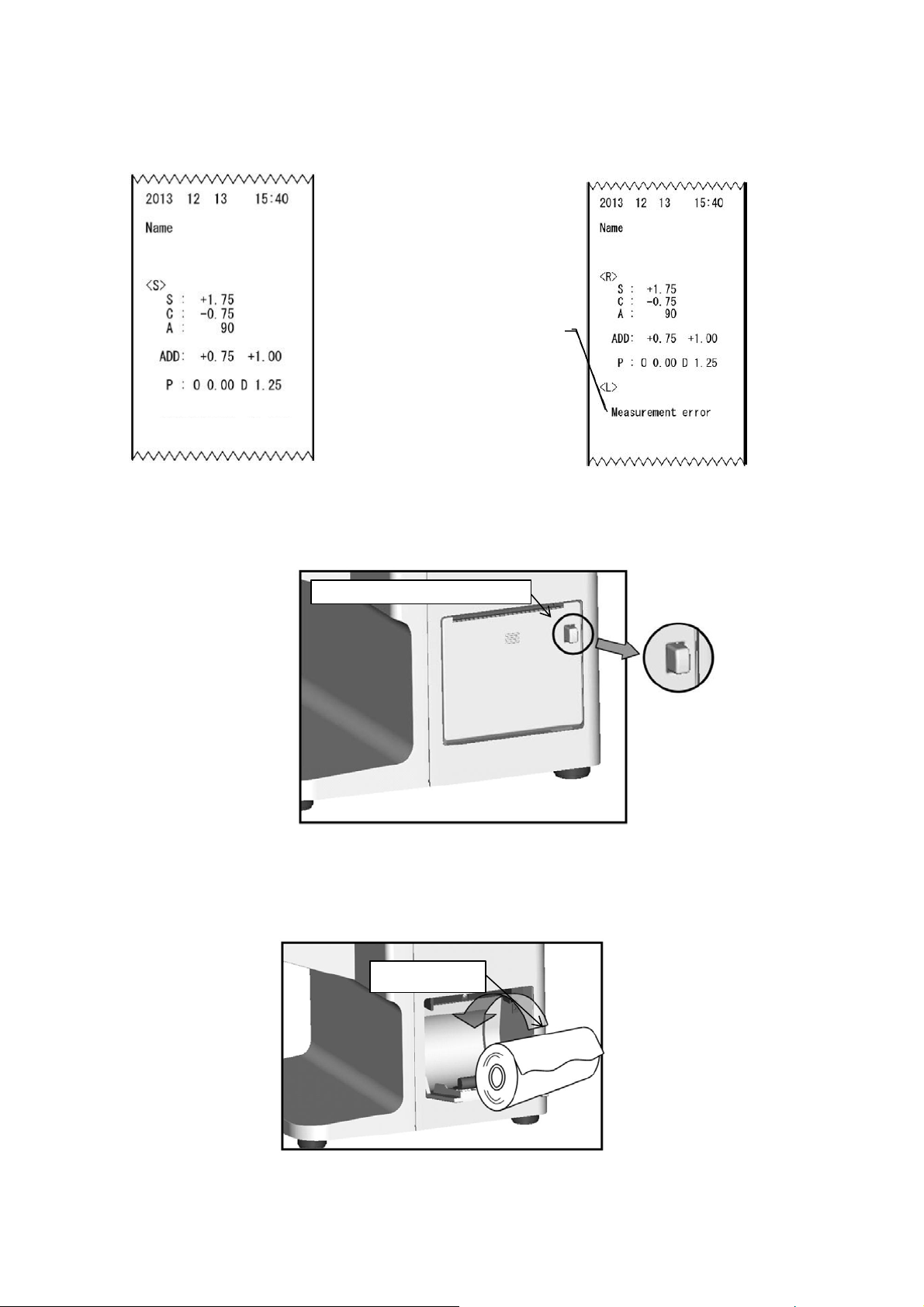
【Printout sample when
unprocessed lens is measured】
ESSILOR ALM700
Other error displays
・SPH Over
・CYL Over
・Prism Over
・Center Error
Error display
5.4.2 Installation and Replacement of Printer Paper
(1) Open the printer cover by pressing the printer cover button.
【Printout sample in case of
measurement error】
ESSILOR ALM700
(2) Insert the printer paper with attention to the winding direction.
Note) Insert the printer paper so as that the printer paper comes out from the upside.
Printer cover button
Printer paper
22
Page 25
(3) Close the printer cover with the end of the paper taken out a little.
At this time, close it completely until hearing the clicking noise. The error is displayed and
the data is not printed out if the cover is opened.
Printer paper
Use the printer paper specified for “ALM700”.
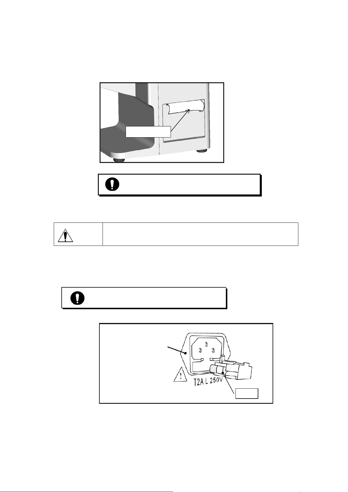
5.5 Replacement of Fuse
Unplug the power cord before removing the fuse holder at the time of
Warning
When the fuse is brown out, replace it after removing the fuse holder of the power inlet. The
fuse holder is removed from the main unit by pulling it out.
replacing the fuse.
Electric shock may occur if removing the fuse holder without
Always use the specified fuse (T2A L 250V).
Power inlet
(with fuse holder)
Fuse
23
Page 26

6. Measurement
6.1 Checkup before Measurement
The lens holder is set properly.
The lens under the lens stand is clean.
(In case that the lens is dirty, clean it with
a soft cloth.)
Plug the power cord to the outlet.
Set the printer paper in the printer.
(Refer to “5.4.2. Installation and Replacement of Printer Paper”.)
Always connect the earth terminal to a ground.
Lens stand is removed
Lens under
lens stand
Confirm that the lens is not placed on the lens stand.
Turn on the power switch. The screen is displayed in seconds.
Single lens measurement screen
Spherical degree
Cylindrical degree
Cylindrical axis
Prism value
Basal angle
Cross cursor
Measurement value
display area
24
Page 27

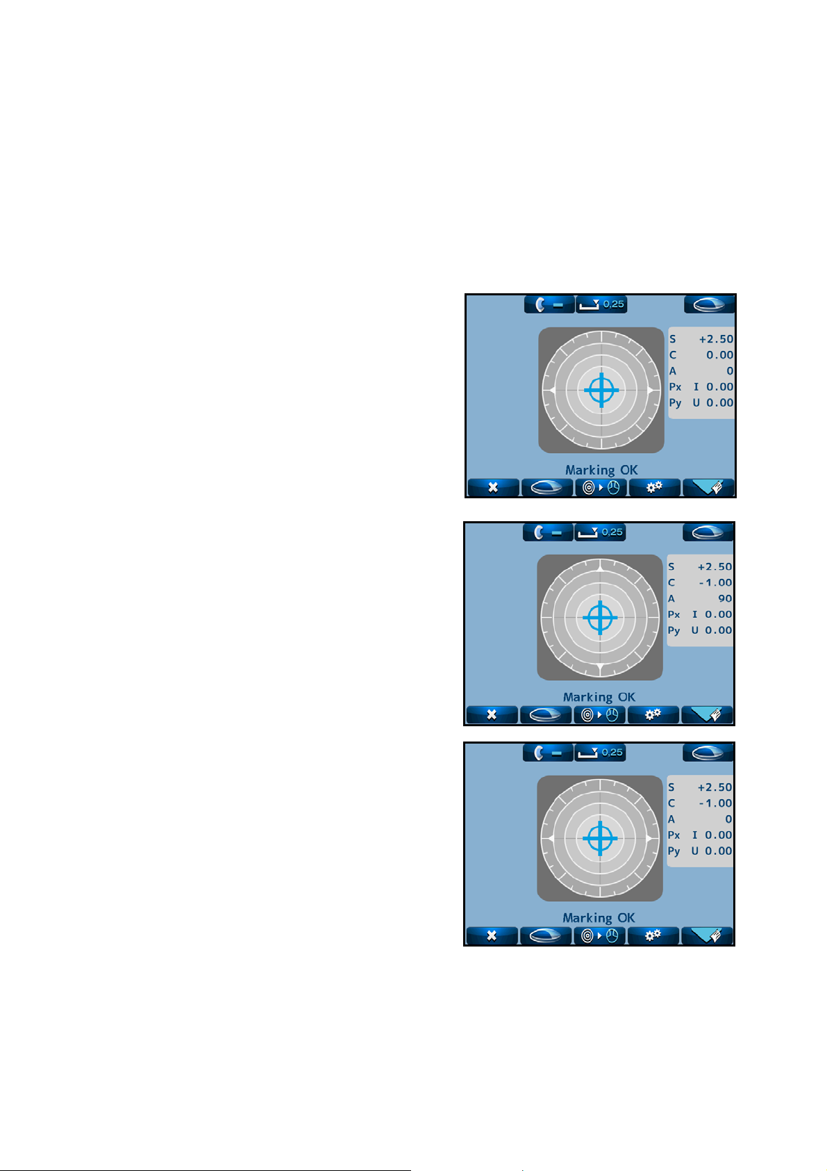
6.2 Measurement of Single Lens
(1) Place the lens on the lens stand.
Lower the lens holder softly on the lens.
The screen as shown on the right appears.
(2) Bring the cross cursor to the alignment mark by
moving the lens. The message “Alignment OK”
appears on the screen when alignment completes.
If the lens is the cylindrical one, rotate the lens
to fit the axis direction.
(3) Move the lens until the alignment mark and
cross cursor overlap. When they overlap, the
message “Marking OK” appears to indicate that
the marking is ready to be carried out.
S, C, A and prism value are stored by pressing
the Memory/Add switch.
The color of the measurement value area is
reversed, and the values are fixed.
※ In case of setting “Auto Memory” on the
Memory/Add
Do not give strong impact to a lens when lowering the lens holder.
When rising the lens holder, make sure that it is moved to the top and locked.
The alignment mark represents the optical center of the lensmeter and the
NOTE
cross cursor represents the optical center of the lens.
Setup screen as “On”, the measurement
values are stored in memory automatically
after the message “Marking OK” appears.
In case of deleting the data stored in
memory, touch
In case of printing it out, touch
switch
Alignment mark
Cross cursor
.
25
Page 28

6.3 Measurement of Framed Lens
Lens holder
(1) Place the framed lens on the lens stand and lower the
lens holder softly on the lens. Move the lens plate to the
near side with the lens plate lever so that the bottom of
the lens touches the lens plate.
(2) Specify the right or left of the framed lens by touching
. The icon in the upper right corner of the screen
switches to
.
(3)
Perform alignment so as that the bottom of the framed
lens always touches the lens plate in a manner similar to
the single lens.
(4) Save the measurement values in memory by pressing the
Memory/Add switch after measurement.
The color of the measurement value area is changed, and
the measurement values are fixed.
In case of setting “Auto Memory” on the Setup screen as “On”, the measurement values
NOTE
are automatically stored in memory after the message “Marking OK” appears.
(5)
Switch the lens from right to left and place the lens in
a manner similar to (1).
Switch the measurement to the left lens by touching
Lens plate
. At this time, the measurement values of the
right lens remain on the screen.
In case of measuring PD with the setting of PD Measure
On, the right eye and left eye are switched automatically.
The measurement of the lens can be started from either right or left.
In case that the measurement values of both right and left are stored, the
NOTE
values on the selected side are deleted by touching
26
.
Page 29

6.4 Pupillary Distance (PD) Measurement
6.4.1 Device Setting
On the setup screen, confirm that “PD Measure” is set as “On”, and the lens measurement is set
for both of right and left lens.
※ In case that “PD Measure” is “Off”, the PD measurement value and measurement area are
not displayed.
6.4.2 Measurement Procedure (Right lens ⇒ Left lens)
(1) Pull the lens plate toward the examiner.
(2) Place the framed lens so as that the bottom of the frame
contacts with the lens plate with the frame contacting with
the left nose pad
and hold it with the lens holder softly.
(3) Achieve an alignment by moving the right lens back and
forth, and right and left with the frame always
contacting with the lens plate. Store the measurement
values and PD measurement values of the right lens
by pressing the Memory/ Add switch after
completing alignment.
(4) After the measurement of right lens, place the left lens
on the lens stand with the frame contacting with the
right nose pad
softly. At this time, it is switched from right lens to left
lens automatically based on the position of the nose pad.
(5) In a manner similar to (3), achieve an alignment of the left lens. After
completing alignment, store the measurement value of the right lens and PD
measurement values by pressing the Memory/ Add switch.
NOTE
In case that “Auto Memory” on the setup screen is set as “On”, the measurement
values are stored automatically after the message “Marking OK” is displayed.
. Place the right lens on the lens stand
, and hold the lens with the lens holder
Measurement screen
Measurement of right lens
Measurement of left lens
Left PD
measurement value
+3 +3
Right and left PD measurement values
27
Right PD
measurement value
Page 30

6.5 Measurement of Multifocal Lens
(1) Place the lens on the lens stand and hold it with the
lens holder softly.
(2) Take a measurement of far point, and press the
Memory/ Add switch. SPH, CYL, AX and prism values
are stored. The measurement result stored is fixed,
and color of the measurement value display area
changes. “Ad1” is added by pressing the Memory/ Add
switch one more time.
(3) Perform the measurement of near point after
confirming that “Ad1” is displayed. Move the lens
so as that the near point (near-sight segment)
comes to the center of the lens stand.
NOTE
A measurement can be taken even if
the messages of “Alignment OK” and
“Marking OK” are not displayed.
Near point
(Near-sight segment)
(4) Store the ADD value of the near point (near-sight
segment) in memory by pressing the Memory/Add
switch. The color of the Ad value is reversed after
storing it.
In case of trifocal lens, display “Ad2” by pressing
the Memory/Add switch one more time. After that,
repeat (3) and (4) after bringing the second near
point (near-sight segment) to the center of the lens
stand.
Refer to “6.3. Measurement of Framed Lens ”
Display of ADD value
28
Page 31

6.6 Measurement of Progressive Lens
(1) Take a measurement of progressive lens.
Set “Auto Prog.” and “ADD Measure”.
(2) Switching to progressive lens measurement screen
NOTE
Auto Prog.
Off :No auto judgment for a progressive lens
On :Auto judgment for a progressive lens
ADD Measure
F/N.AT :Auto memory of far and near points
N.AT :Auto memory of near point
Manual :Manual memory of far and near points
The icon is changed to
, and the progressive
lens measurement screen is displayed by pressing
(single/ progressive lens selection switch).
In case that Auto Prog is set as “On”, the lens is automatically judged whether the lens
is a progressive lens or not.
Set the lens in the center region of the progressive zone. It starts the auto judgment of
the progressive lens. When the lens is identified as a progressive lens, the screen is
switched to the progressive lens measurement screen. If not, the measurement screen
remains as the single focus lens measurement screen.
When the ADD value is small (less than 1D), the auto detection may not be performed.
Also, if the progressive zone cannot be found at where the lens is set, the auto detection
may not be performed.
In these cases, move the lens back and forth, and right and left slowly.
When the ADD value is small (less than 1D), the framed lens is small, or the lens is dirty
or has some flaws, the far point and near point may not be detected automatically. In
such case, take a measurement manually.
29
Page 32

(3) Measuring procedure of progressive lens (when N.AT is selected for ADD Measure)
1) Detection of progressive zone
First, find the progressive zone by moving the lens back and forth, and right and left slowly.
The cross cursor (screen shown below) appears when the progressive zone is found.
NOTE
Press the Memory/Add switch in case that the progressive zone cannot be detected
because ADD value is small etc. It switches to the measurement screen of the far point.
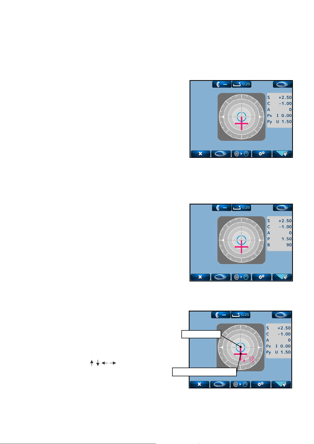
2) Measurement of far point
Take a measurement of far point. Move the lens toward the
device so as that the center of the alignment mark overlaps
with the cross cursor.
The color of the cross cursor is changed to blue by pressing
the Memory/Add switch after they overlaps.
At this time, the measurement values of the far point
are stored.
NOTE
3) Measurement of near point
When “ADD Measure” on the Setup screen is set as “F/N.AT”, it is detected
automatically and the measurement values are stored in memory.
Progressive area
Take a measurement of near point. As shown on the right,
move the lens slowly
to move the cross cursor (red)
according to
. If it goes out of the progressive zone, the
cross cursor moves right or left. If it goes out of the
progressive zone, bring it back to the zone and move the lens
toward near point.
NOTE
The cross cursor on the screen indicates the actual
measurement position on the lens. For example, if it
goes to the right side of the lens which is out of the
progressive zone at the time of moving from far point
to near point, the cross cursor is displayed on the
right deviated from the progressive zone.
Perform the alignment carefully when it comes closer to the
near point and
starts blinking. Once the near point is
detected, it blips. The cross cursor is fixed at the near point
and its color changes to blue. When the near point is attained,
the ADD value is stored in memory automatically.
※Another ADD value (Ad2) can be stored in memory anywhere
by pressing the Memory/Add switch after measurement.
The progressive judgment screen appears again by setting
+2
25
the lens for the left eye and touch
after completing
the measurement. Take a measurement of the left lens in the
same manner as right lent.
※Measurement can be started from either right or left lens.
30
Page 33

A
A
(4) Display of ADD value and assessment graph, and manual operation
(when “Manual” of “ADD Measure” is selected)
When setting “Prog. Graph” as “On” on the Setup screen, the graph is displayed on the
progress lens measurement screen.
Depending on the type of lens, it may be difficult to detect each point automatically even
though normally the near and far points are detected automatically. In such case, take a
measurement manually by reference to the ADD value and assessment graph.
To take a measurement of far point manually, carry out the alignment in the same manner
as the auto measurement.
For the measurement of near point, press the Memory/Add switch where the ADD value is
the highest while the alignment cursor stays in the progressive area.
The near point is where the assessment line moves closer to the Y coordinate. Therefore,
carry out alignment by reference to the shape of the graph and blinking of
ssessment lineADD value line
High Low
【Framed lens: reference】
Near the center of lens
pprox. 5 to 10mm
Far point
.
Graph
31
Page 34

6.7 Measurement of Ultraviolet (UV) Transmission
Checks the UV protection function by taking a measurement of the UV transmission of lens.
The light wavelength for UV transmittance measurement is 375 nm. This does not measure the transmittance
of a whole area of UV light.
6.7.1 Device Setting
Confirm that “UV Measure” is set as “On” before the measurement of UV transmission.
※ In case of setting “UV Measure” as “Off”, neither UV transmission nor UV transmission
display area is displayed.
If displaying UV transmission graph, set “UV Graph” as “On”.
※ The graph is displayed only in the progressive lens measurement mode.
(Refer to 4.2.1. Device Setting.)
6.7.2 Measurement of UV Transmission after Measuring Degree
The UV transmission measurement is performed after achieving an alignment of the lens and
pressing the “Memory/Add switch” to store the measurement values.
NOTE
At the time of progressive lens measurement, the UV transmission measurement is
performed after taking a measurement of far point
.
In case of taking a measurement again, clear the measurement values first by touching
※The values are cleared in order of degree of lens and UV transmission.
UV transmission graph
UV transmission
.
32
Page 35

6.8 Measurement of Contact Lens
6.8.1 Preparation
(1) In case of taking a measurement of hard contact
lens, select “H CL” on Setup screen. In case of
taking a measurement of soft contact lens, select
“S CL” on Setup screen.
(2) Change the lens stand to the accompanying
contact lens stand.
6.8.2 Measurement Procedure
(1) Set the contact lens on the contact lens stand as shown below.
Contact lens
Contact lens stand
(2) Replace the standard lens stand with the contact lens stand.
(3) Lower the lens holder, and hold the contact lens stand which the contact lens is already
placed.
NOTE
Contact lens stand
Remove the water or moisture from the lens, and set it
on the stand with paying attention not to distort it.
Then, take a measurement quickly.
A bifocal contact lens cannot be measured.
Contact lens stand
33
Page 36
7. Marking
Refer to “5.3. Marking Lever.”
7.1 Lens without Astigmatism
(1) Overlap the cross cursor with the alignment mark
on the screen by moving the lens.
You are ready for marking when the message
“Marking OK” is displayed.
(2) Lower the marking lever to mark on the lens.
7.2 Lens with Astigmatism
Marking according to the axis in the prescription
(1) Move the lens so as that the axis mark aligned with
the angle in the prescription approximately.
(2) To be more precise, align it according to the axis
value indicated.
Marking on the cylindrical axis
(1) Move the lens so as that the axis mark aligned with
0° approximately.
(2) To be more precise, align it so as that the axis value
indicated becomes 0°.
34
Page 37
7.3 Marking of Prism Lens
In case that prescription is expressed in X-Y
(1) Select “X-Y” from “Prism” on the “Setup” screen.
(2) Move the lens so that the prism values displayed on
the screen match with the ones on the prescription.
The meanings of the prism values displayed are as
shown below.
Px I Base In (base inward)
Px O Base Out (base outward)
Py U Base Up (base upward)
Py D Base Down (base downward)
In case that prescription is expressed in P-B
(1) Select “P-B” from “Prism” on the “Setup” screen.
(2) Move the lens so that the prism values displayed
on the screen match with the ones in the
prescription.
P: Prism value
B: Base direction
In case that prescription is expressed in mm
(1) Set “Prism (mm)” as “On” on the “Setup” screen.
(2) Move the lens so that the prism values displayed
on the screen match with the ones in the
Optical center
prescription.
The arrows ( ) indicate the direction of
the measuring position on the lens from its
optical center.
Measurement position
35
Page 38
A
8. Other Functions
8.1 Auto Memory Function
This device has the function to store the measurement values in memory automatically when
the alignment is achieved, and the message “Marking OK” is displayed at the time of the
measurements of single focal lens, multifocal lens and contact lens.
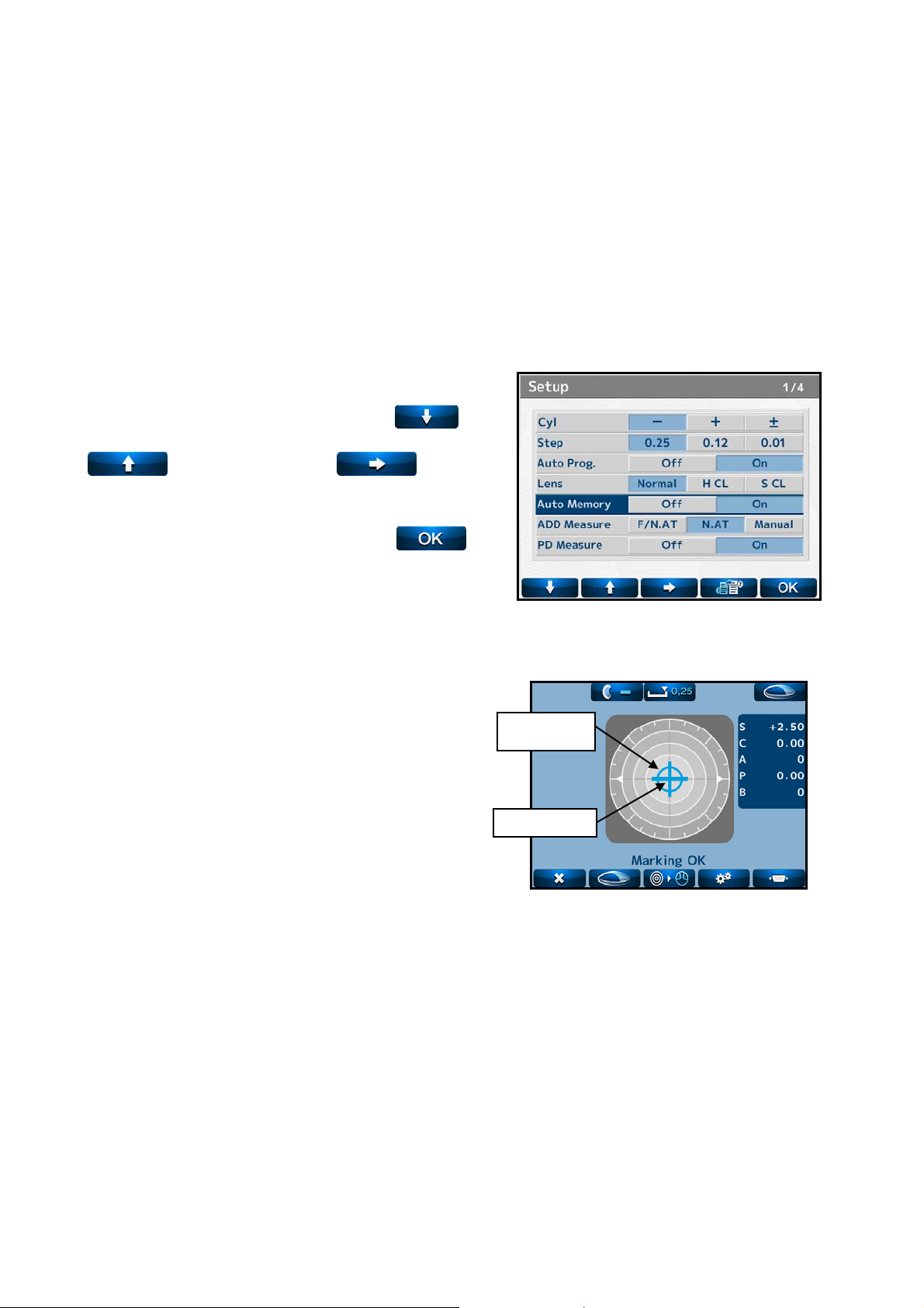
8.1.1 Operation Procedure
Move the cursor to “Auto Memory” with or
and select “On” with .
Return to the measurement switch with
after the settings or changes are completed.
he measurement values are stored in memory
automatically when the message “Marking OK”
appears after the alignment mark and cross cursor
overlap as shown on the right.
mark
Cross cursor
lignment
+2.50
36
Page 39

8.2 Power Saving Function
The power saving function is activated if no switches are operated or no measurement values
are updated with the power on. The switching time to the power saving mode can be set on
“Standby” of the Setup screen.
Power indicator (PW) Light on
Power indicator (PW) Blinking
Power indicator (PW) Light on
Measurement mode
No operation for a set time
Power saving
Return to measurement mode
Press any switch
While this function is activated, the power to
the measurement light and LCD monitor is
turned off.
It returns to the measurement mode by
pressing any switch.
37
Page 40

9. Error Display
An error message appears when the measurement condition or measurement result is judged
as unreasonable. Also, an error message appears when the performance of the device is
abnormal.
9.1 Type
※ Display with a three-digit code (number)
Message Status Error Detail
Any of the measurement values is more than “±0.25”.
Initial Error
Paper Empty No printer papers.
Printer Cover Opened Printer is opened.
Printer Overheated Printer head is overheated.
EEPROM Failure Abnormality of memory
Sensor Error Abnormality of CMOS sensor
※Error * * * (100 -163)
SPH Over
CYL Over
Prism Over
ADD Over
Measurement Error
Center Error
Abnormality
of device
Measurement
abnormality
Abnormality
of image
processing
Lens is set on the lens stand.
Abnormal measurement because of dust or
unnecessary light.
Abnormality of electronic parts
SPH measurement value is more than the upper
limit of the measurement range.
CYL measurement value is more than the upper
limit of the measurement range.
The prism measurement value is more than the
upper limit of the measurement range.
ADD measurement value is more than the upper
limit of the measurement range
Abnormal light receiving image because of dust,
scratch on lens or unnecessary light etc.
(The measurement light does not enter into the light
receiving sensor normally.)
Measurement light LED does not light on.
Unexpected light receiving image because of
unnecessary light.
38
Page 41

9.2 Error Handling Procedure
Warning
Do not disassemble, remodel or repair.
It may cause electric shock.
・Initial Error
This message appears if the lens is placed on the lens stand when the power is turned on or
the lens under the lens stand is dirty.
Remove the lens. When the lens under the lens stand is dirty, gently wipe it with a soft
cloth. After that, turn the power back on.
(Refer to “6.1 Checkup before Measurement”.)※
・Paper Empty
This message appears if no papers are set or papers are not set appropriately.
Set the paper appropriately. (Refer to “5.4.2 Installation and Replacement of Printer
Paper”.)
・Printer Cover Opened
This message appears when the printer cover is opened. Check the cover and close it
properly.
・SPH/CYL/Prism/ADD Over
This message appears in case of measuring the lens which exceeds the upper limit of the
measurement range of the device.
Take a measurement of the lens within the measurement range
(Refer to “11. Specification”.)
・Measurement Error or Center Error
This message appears when the direct sunlight or strong glare is on the device, or the lens
under the lens stand is extremely dirty or has scratches.
If the lens under the lens stand is extremely dirty, gently wipe it with a soft cloth. Then,
turn the power back on.
If an error message other than shown above is displayed or an error message
is still displayed even after performing the procedure above, turn off the
power, disconnect the power cord and contact your local distributor.
39
Page 42

10. Storage of Device
(1) Points to be checked for long-term storage
Turn OFF the power.
Remove the power cord from the outlet.
Put the dust proof cover on the main unit.
(2) Notes on storage environment
(3) Avoid storage under the following conditions
Dusty place
Where water may get on the device
High-temperature and humidity
Where sunlight directly contacts
Unstable and high place
Observe the environment conditions below for storage.
Environmental condition for storage
Check the above in case that the device is not used or is stored for a long time.
When using the device after long-term storage, operate it in accordance with
“4.2 Preparation for Measurement”.
40
Page 43

11. Specification
Sphere -25D to +25D (0.01/0.12/0.25 step)
Cylinder 0 to ±10D (0.01/0.12/0.25 step)
Measurement range
Measurable lens
Measurement
wavelength
UV transmission
UV transmission
measurement
wavelength
PD measurement
Power Rating
Power Consumption 40VA
Printer Thermal printer (paper width 58mm)
Monitor Color LCD monitor (5.7 inches)
Size, weight
Environmental
condition of use
Axis 0 to 180° (1°)
Addition 0 to +10D (0.01/0.12/0.25 step)
Prism
Unprocessed lens
(diameter:100mm)
Framed processed lens
Hard contact lens
Soft contact lens
525nm
0 to 100% (-25D to +25D)
375nm (UV-A)
45 to 85mm (0.5mm step)
100 to 240V
50/60Hz
170mm(W)×205mm(D)×468mm(H)(400mm: when the monitor is stored)
Approx. 4.3kg
Temperature range: 5 to 40
Humidity range: 30 to 95%HR (No dew condensation allowed)
0 to 10△
Single lens, multifocal lens, progressive
lens
Accompanying lens stand is required
(0.01/0.12/0.25 step)
41
Page 44

12. EMC (Electromagnetic Compatibility)
This device conforms to the requirements of the EMC (electromagnetic compatibility) standard
as shown below.
Guidance and manufacturer’s declaration – electromagnetic emissions
This device is intended for use in the electromagnetic environment specified below.
The customer or user of this device should assure that it is used in such an environment.
Emission test Compliance Electromagnetic environment – guidance
RF emissions
CISPR11
RF emissions
CISPR11
Harmonic
emissions
IEC 61000-3-2
Vol ta ge
fluctuations/
flicker emissions
IEC 61000-3-3
Group 1
Class A
Class A
Complies
This device uses RF energy only for its internal function.
Therefore, its RF emissions are very low and are not likely to
cause any interference in nearby electronic equipment.
This device is suitable for use in all establishments other than
domestic and those directly connected to the public
low-voltage power supply network that supplies buildings
used for domestic purposes.
42
Page 45

Guidance and manufacture’s declaration – electromagnetic immunity
This device is intended for use in the electromagnetic environment specified below.
The customer or user of this device should assure that it is used in such an environment.
Immunity test
Electrostatic
discharge
(ESD)
IEC 61000-4-2
IEC 60601
test level
±6kV contact
±8kV air
Compliance level
±6kV contact
±8kV air
Electromagnetic environment
- guidance
Floors should be wood,
concrete of ceramic tile. If
floors are covered with
synthetic material, the
relative humidity should be
at least 30%.
Electrical fast
transient/ burst
IEC 61000-4-4
Surge
IEC 61000-4-5
±2kV for power
supply lines
±1kV for input/
output lines
±1kV differential
mode
±2kV common mode
±2kV for power
supply lines
±1kV for input/
output lines
±1kV differential
mode
±2kV common mode
Mains power quality should
be that of a typical
commercial or hospital
environment.
Mains power quality should
be that of a typical
commercial or hospital
environment.
Voltage dips,
short
interruptions
and voltage
variations on
power supply
input lines
IEC 61000-4-11
Power
frequency
(50/60Hz)
Magnetic field
IEC 61000-4-8
<5 %
U
T
(>95% dip in
for 0.5cycle
40 %
U
T
(60% dip in
for 5 cycles
70 %
U
T
(30% dip in
for 25 cycles
<5 %
U
T
(>95% dip in
for 5s
U
U
U
U
T)
T)
T
T)
)
<5 %
U
T
(>95% dip in
for 0.5 cycle
40 %
U
T
(60% dip in
for 5 cycles
70 %
U
T
(30% dip in
for 25 cycles
<5 %
U
T
(>95% dip in
for 5s
U
U
U
U
)
T
)
T
)
T
)
T
3A/m 0.3A/m If image distortion occurs, it
Mains power quality should
be that of a typical
commercial or hospital
environment. If the user of
this device requires continued
operation during power
mains interruptions, it is
recommended that this device
be power from an
uninterruptible power supply
or a battery.
may be necessary to position
the device further from
sources of power frequency
magnetic fields or to install
magnetic shielding. The
power frequency magnetic
field should be measured in
the intended installation
location to assure that it is
sufficiently low.
NOTE
U
is the a.c. mains voltage prior to application of the test level.
T
43
Page 46

Guidance and manufacturer’s declaration – electromagnetic immunity
This device is intended for use in the electromagnetic environment specified below. The
customer or the user of this device should assure that it is used in such an environment.
Immunity test
Conducted RF
IEC 61000-4-6
Radiated RF
IEC 61000-4-3
IEC60601
test level
3 Vrms
150 kHz to 80
MHz
3 V/m
80 MHz to 2.5
GHz
Compliance
level
3 Vrms
3 V/m
Electromagnetic environment - guidance
Portable and mobile RF communications
equipment should be used no closer to any
part of this device, including cables, than
the recommended separation distance
calculated from the equation applicable to
the frequency of the transmitter.
Recommended separation distance
√
d
=1.2
P
√
d
=1.2 80 MHz to 800 MHz
P
√
d
P
=2.3 800 MHz to 2.5 GHz
where P is the maximum output power
rating of the transmitter in watts (W)
according to the transmitter manufacturer
and
d
is the recommended separation
distance in metres (m).
Field strengths from fixed RF
transmitters, as determined by an
electromagnetic site survey,
a
should be less
than the compliance level in each
frequency range.
b
Interference may occur in the vicinity of
equipment marked with the following
symbol:
NOTE 1 At 80 MHz and 800MHz, the higher frequency range applies.
NOTE 2 These guidelines may not apply in all situations. Electromagnetic propagation is
affected by absorption and reflection from structures, objects and people.
a
Field strengths from fixe transmitters, such as base stations for radio (cellular/cordless)
telephones and land mobile radios, amateur radio, AM and FM radio broadcast and TV
broadcast cannot be predicted theoretically with accuracy. To assess the electromagnetic
environment due to fixed RF transmitters, an electromagnetic site survey should be considered.
If the measured field strength in the location in which this device is used exceeds the applicable
RF compliance level above, this device should be observed to verify normal operation. If
abnormal performance is observed, additional measures may be necessary, such as re-orienting
or relocating this device.
b
Over the frequency range 150kHz to 80MHz, field strengths should be less than 3 V/m.
Recommended separation distances between portable and mobile RF communications
equipment and this device
This device is intended for use in an electromagnetic environment in which radiated RF
44
Page 47

disturbances are controlled. The customer or the user of this device can help prevent
electromagnetic interference by maintaining a minimum distance between portable and mobile
RF communications equipment (transmitters) and this device are recommended below, according
to the maximum output power of the communications equipment.
Separation distance according to frequency of transmitter
m Rated maximum
output power of
transmitter
W
0.01 0.12 0.12 0.23
0.1 0.38 0.38 0.73
1 1.2 1.2 2.3
10 3.8 3.8 7.3
100 12 12 23
For transmitters rated at a maximum output power not listed above, the recommended
separation distance d in metres (m) can be estimated using the equation applicable to the
frequency of the transmitter, where
watts (W) according to the transmitter, where
transmitter in watts (W) according to the transmitter manufacturer.
NOTE 1 At 80 MHz and 800MHz, the separation distance for the higher frequency range
applies.
NOTE 2 These guidelines may not apply in all situations. Electromagnetic propagation is
affected by absorption and reflection from structures, objects and people.
150kHz to
80MHz
√
d
=1.2
P
P
80MHz to
800MHz
√
d
=1.2
P
is the maximum output power rating of the transmitter in
P
is the maximum output power rating of the
800MHz to 2.5GHz
√
d
=2.3
P
45
Page 48

46
Page 49
Page 50

Essilor Instruments USA
8600 W. Catalpa Avenue, Suite 703
Chicago, IL 60656
Phone: 855.393.4647
Email: info@essilorinstrumentsusa.com
www.essilorinstrumentsusa.com
 Loading...