

Esse-ti Hi-Pro 1 Series, Hi-Pro 412 Rack (ISDN), Hi-Pro 280 Installation And Programming Manual

Installation and Programming
MANUAL

Thank you for choosing an Esse-ti product
This product has been especially designed for
easy operation. It has been manufactured with
perfect workmanship using suitable materials for
long-lasting performance.
All Esse-ti products are subjected to extensive
reliability and operational testing in our
laboratories in order to provide total guarantee
for the user.
The User shall be responsible for defects arising from the use of the product. Esse-ti
shall only be responsible for defects according to and within the limitations set by the
Presidential Decree dated 24/05/1988 no. 224 (fulfilling the EEC directive no. 85/374 on
the harmonization of statutory and administrative regulations of the Member States on
the liability for damages arising from defective products under art. 15 of Law no. 183 of
16 April 1987).
Esse-ti reserves the right to modify the characteristics of the products at any time
without prior notice.

TABLE OF CONTENTS
General instructions for the installer ....................................................................................... 9
General Notes ..................................................................................................................... 9
Making the Installation ..................................................................................................... 10
Warnings .......................................................................................................................... 10
DESCRIPTION .................................................................................................................... 11
Default configurations ................................................................................................................. 12
User Profiles ................................................................................................................................ 12
HI-PRO 280 .......................................................................................................................... 13
Hardware Description .................................................................................................................. 13
Terminals ..................................................................................................................................... 14
LEDs ............................................................................................................................................ 15
DIP switches ................................................................................................................................ 15
HI-PRO 280 Installation ................................................................................................... 16
Recommendations ........................................................................................................................ 16
Operations to perform .................................................................................................................. 16
Accessory connections ..................................................................................................... 19
PSTN (analogue lines) optional board ......................................................................................... 19
ISDN Optional board ................................................................................................................... 19
Doorphone optional board ........................................................................................................... 21
Doorphone connection ................................................................................................................. 22
Actuator Relays ........................................................................................................................... 22
External Music on-hold source .................................................................................................... 23
Amplifier ..................................................................................................................................... 24
Digital Input ................................................................................................................................. 25
Connection to the PC ........................................................................................................ 26
Working in Emergency Mode .......................................................................................... 27
Maintenance ..................................................................................................................... 27
HI-PRO 412 RACK (ISDN) ................................................................................................. 28
Front panel description ................................................................................................................ 28
Hardware description ................................................................................................................... 29
DIP switches ................................................................................................................................ 29
HI-PRO 280 RACK (ISDN) Installation .......................................................................... 30
Recommendations ........................................................................................................................ 30
Installation ................................................................................................................................... 30
Operations to perform .................................................................................................................. 31
Optionals Connection ....................................................................................................... 33
Batteries ....................................................................................................................................... 33
Optional o Integrated Doorphone Board ...................................................................................... 34
Connecting Doorphone ................................................................................................................ 35
Actuator relays ............................................................................................................................. 37
External Music source ................................................................................................................. 37
Amplifier ..................................................................................................................................... 38
Digital input ................................................................................................................................. 39
Connection to the PC ........................................................................................................ 40
Maintenance ..................................................................................................................... 40
Programmings to be performed during installation phase ..................................................... 41
Setting a default configuration ......................................................................................... 41
Programming for call forwarding ..................................................................................... 47

Programming of the switchboard model and of the internal connection to the personal
phone ................................................................................................................................ 48
PROGRAMMINGS .............................................................................................................. 49
Access to programming .................................................................................................... 51
Password .......................................................................................................................... 52
Modifying the installer password ................................................................................................. 52
Modifying the user password ....................................................................................................... 52
Remote Programming number.......................................................................................... 53
Device reset ...................................................................................................................... 54
Restoring the factory settings ........................................................................................... 54
Deleting the phonebook and the buffer memory .......................................................................... 55
Clock ................................................................................................................................ 55
Date ............................................................................................................................................. 55
Time ............................................................................................................................................ 55
Profiles ............................................................................................................................. 57
Daily time band ........................................................................................................................... 57
Weekly time band ........................................................................................................................ 59
Numbering........................................................................................................................ 60
Extension numbering ................................................................................................................... 60
Internal call group ............................................................................................................ 61
Call group numbering .................................................................................................................. 61
Creating call groups ..................................................................................................................... 62
Trunk lines programming ................................................................................................. 62
ISDN options .................................................................................................................... 63
Type of ISDN line ....................................................................................................................... 63
TEI programming ........................................................................................................................ 64
BRI Numbers programming......................................................................................................... 64
Incoming calls managing ............................................................................................................. 65
IDs Managing .............................................................................................................................. 67
Extension programming ................................................................................................... 69
Outgoing calls .............................................................................................................................. 69
Doorphone calls ........................................................................................................................... 71
Unrestricted numbers ................................................................................................................... 72
Service activation ......................................................................................................................... 73
Incoming calls .................................................................................................................. 76
Programming incoming calls ....................................................................................................... 77
Line activation for external call forwarding ..................................................................... 79
Analogue Lines ............................................................................................................................ 79
ISDN Lines .................................................................................................................................. 80
Enabling doorphone call forwarding ................................................................................ 81
FAX .................................................................................................................................. 82
Programming the fax extension ................................................................................................... 83
FAX-switch activation ................................................................................................................. 84
Messages .......................................................................................................................... 86
Message recording/playbac/deleting ............................................................................................ 86
Activate musical backgroung ....................................................................................................... 87
Message protection ...................................................................................................................... 88
Creating message sequences ........................................................................................................ 88
Deleting message sequences ........................................................................................................ 89
Activate musical backgroung for message sequences .................................................................. 89
Response service .............................................................................................................. 90
Choosing the Response message .................................................................................................. 90

Response programming ............................................................................................................... 91
DISA service .................................................................................................................... 92
Choosing the DISA message........................................................................................................ 92
DISA programming ..................................................................................................................... 93
Delayed DISA programming ....................................................................................................... 94
Automatic operator (IVR) ................................................................................................ 95
Assigning a IVR menu to a line ................................................................................................... 96
Automatic operator (IVR) programming ..................................................................................... 97
Assign the menu prompting message ........................................................................................... 98
Prompting message recording/playback ....................................................................................... 99
Defining menu events .................................................................................................................. 99
Defining the “Operating button” event ...................................................................................... 102
Service classes ................................................................................................................ 103
Operating rules .......................................................................................................................... 103
Entering filtre sequences in a service class ................................................................................ 103
Removing filter sequences from a service class ......................................................................... 104
Deleting a service class .............................................................................................................. 104
L.C.R. ............................................................................................................................. 105
Assigning the lines to a service class ......................................................................................... 105
Assigning a provider to a service class ...................................................................................... 106
Deleting a provider code ............................................................................................................ 107
Actuator relay configuration ........................................................................................... 107
ST series telephones memory buttons ............................................................................ 108
Assigning a service to a memory button .................................................................................... 109
Deleting a service from a memory button .................................................................................. 110
External music source .................................................................................................... 110
Input enable ............................................................................................................................... 110
Activation over analogue lines ................................................................................................... 110
Activation over ISDN lines ........................................................................................................ 111
Testing External music source ................................................................................................... 111
Amplifier ........................................................................................................................ 112
Phonebook ...................................................................................................................... 113
Storing a telephone number ....................................................................................................... 113
Deleting a stored number ........................................................................................................... 113
ACD ............................................................................................................................... 114
Address to a single extension ..................................................................................................... 114
Assigning a stored number to a VIP line .................................................................................... 115
Memory Buffer ............................................................................................................... 116
Incoming calls ............................................................................................................................ 116
Outgoing calls ............................................................................................................................ 116
Remote clearing recognition ........................................................................................... 117
Sampling extension flash time ........................................................................................ 117
Remote programming ......................................................................................................... 119
Access from the Remote Programming Number ........................................................................ 119
Access through user consent ...................................................................................................... 119
Access from IVR menu .............................................................................................................. 119
SIGNALATIONS ............................................................................................................... 120
Tones .............................................................................................................................. 120
Call signals (Rings) ........................................................................................................ 121
Technical specification ....................................................................................................... 123
System capacity ......................................................................................................................... 123
Power supply ............................................................................................................................. 123
Signalling system ....................................................................................................................... 123

Other features ............................................................................................................................ 123
Lines .......................................................................................................................................... 124
Dimensions ................................................................................................................................ 124
Safety system ............................................................................................................................. 124
CE conformity declaration ............................................................................................. 125

CONVENZIONI TIPOGRAFICHE Pagina 7
EDITING CRITERIA
This paragraph describes the editing criteria followed in this manual, together with their
meaning for easier user’s reference. The following table shows the printing styles on the left
and their meaning on the right column.
Example Meaning
CHAPTER
TITLE
Style used for the title of chapters. A new
chapter begins on a new page.
P
RIMARY TITLE
Style used for the title of large sections in a
chapter, such as the main titles of the chapter.
Secondary Title
Style used for the title of a specific paragraph
in the primary title.
Tertiary Title
Style used for additional sections in a specific
paragraph
Example
Style used for examples.
Note
Style used for explicatory notes: pay attention!
Warning
Style used to indicate possible risks for
individuals and properties: caution!
Normal text
Style used for normal text.
Operation to be carried out
Style used to indicate the sequence of
operations that must be carried out for
programming or service implementation.

Pagina 8 EDITING CRITERIA
Apart from these styles, this manual also includes illustrative images and
symbols used to represent the operations to be carried out in a schematic way:
Symbol Meaning
, , , , , ,
, , , , , ,
.
Press the key that corresponds to the symbol
on the telephone keypad.
Indicates a telephone key: this symbol is
used in programming to indicate the entries
made by the operator.
Lift the handset from the Administrator
extension (or activate the handsfree mode).
Programming must be enabled.
Lift the handset from the Administrator
extension (or activate the handsfree mode).
Lift the handset (or activate the
handsfree mode) to engage the line.
Hang up (or deactivate the handsfree
mode) to clear the line.
A | B
The vertical bar indicates that the possible
entry values are ‘A’ or ‘B’.
A [B]
The square brackets indicate optional code
parts that can be omitted.

General instructions for the installer Pagina 9
GENERAL INSTRUCTIONS FOR THE
INSTALLER
G
ENERAL NOTES
Carefully read the notes contained in this section as they provide important
information on the correct safe installation, use and maintenance of the product.
• The product must be EXCLUSIVELY used for the purpose it was designed
for. Esse-ti shall not be responsible for damages arising from improper use.
• The product has been designed in compliance with the regulations in force and
must be installed in system that comply with the provisions of law.
• Before connecting the product to the electric mains, make sure that the line
voltage corresponds to the value indicated on the product label.
• Always disconnect the product from the power supply mains before carrying
out any operation either inside or outside the product (cleaning, maintenance,
etc.).
• A protective cut-out switch must be installed upstream in order to interrupt
power supply in case of fault.
• Always refer to an authorized assistance centre for repair.
• Install the product in a well-ventilated place, making sure not to obstruct the
ventilation slots.
• Beware of symbols showing lightening with arrow inside a triangle since they
indicate the presence of dangerous voltage.
• Beware of symbols showing an exclamation mark inside a triangle since they
indicate potentially dangerous or even lethal situations that require utmost
attention.
• Do not use the product in association with other electric or electronic devices
that were not especially designed to be used with it.
• Do not install the product in potentially explosive environments.
• Make sure that the product has been installed as required.
• Do not introduce objects, liquids or powders inside the product. Do not use
sprays inside the product.
• Do not open the product case since it does not contain any user-serviceable
parts. If necessary, contact an authorized assistance centre.
• In case of gas leaks in the environment do not use the telephone to make an
emergency call.

Pagina 10 General instructions for the installer
• When replacing the batteries, arrange for suitable disposal with similar waste.
• Packing components (such as plastic bags, foam polystyrene, etc.) must be
kept out of the reach of children because potentially dangerous.
M
AKING THE INSTALLATION
Internal telephone installations must be carried out by specialized personnel.
The installation and connection of telephone terminals to the
telecommunications network that do not comply with the regulations in force is
not permitted.
W
ARNINGS
The main causes of interference on telephone lines and power supply mains
(that may result in malfunctioning or damages to the product) are:
• accidental contacts with lines with higher voltage (short circuit)
• electromagnetic association with other conductors located nearby
• sudden load variations, especially for power supply lines (electric motors, etc.)
• temporary interference caused by weather conditions (lightening)
Protections for telephones lines must be inserted not only on external, but also
on extension lines outside the building or lines connected to devices that are
powered from the mains (i.e. fax, modem, answering machine, cordless
telephone, etc.).
The protection for power supply lines must be connected to the input of the
product power line.
The earth terminal of the protections must be connected to a working earth
system to ensure the correct operation of the devices.

DESCRIPTION Pagina 11
DESCRIPTION
Hi-Pro is a performing and professional system, it is particularly suitable for
Companies and SOHO solutions.
The 280 version provides 2 analogue external lines and 8 extensions (optional
board for 2 analogue external lines and 4 extension, or 2 BRI and 4 extensions
are available).
The 412 Rack version provides 4 analogue external lines and 12 extensions.
The 412 Rack ISDN version provides 2 BRI and 12 extensions.
Every model of Hi-Pro is characterized by the following features and
functionalities:
• 7 default configurations for a rapid start-up
• 3 user profiles (DAY, NIGHT, CUSTOM), manual or automatic recall
depending on time bands
• Internal and External Caller ID (FSK standard) on analogue and system
telephone sets
• Display Name if contact of the phone book
(only system telephone set and alphanumeric analogue phones, FSK
standard).
• Built-in Courtesy Responder (1 channel in 280 version and 2 in the 412
one)
• Built-in IVR (Interactive Voice Response) with 10 customizable and
concatenable menus
• Built-in Voicemail
• Built-in DISA Service
• 30 customizable messages
(available for Courtesy Responder, IVR, DISA and Voicemail services)
• 30 minutes available in 280 version and 60 for the 412 one (among
Voicemail and the 30 customizable messages)
• External Waiting message with A/50 or other audio source
• Automatic switch-FAX with the possibility of inserting a different FAX
extension for each external line
• Automatic switch-FAX based on ISDN number, with the possibility of
inserting a different FAX extension for each BRI
• ACD (Automated Call Distribution)
• L.C.R. (Least Cost Routing)

Pagina 12
• External call forwarding
• Doorphone call forwarding
• Telerescue (with ST350 telephone sets)
• Alarm dialler
• Remote Ambient listening via system phones
• Remote relay activation
• Vocal notification of the operations carried out
• 200-entry phonebook
• Buffer ( 1500 incoming/outgoing calls)
• System clock
• Doorphone board to allow connection to traditional doorphones 4+1
(optional for analogue versions, built-in for ISDN versions)
. 2 ringer inputs
. 1 speech input
• 2 programmable relays
• 1 configurable digital inputs
• External amplifier exit
• External music source input
• Up to 8 ST600 Personal Phone telephone systems
• Optional batteries for emergency operation (only Rack models)
• 24Vdc power supply input for emergency operation (only Rack models)
• Local programming via DTMF telephone or via USB port
• Remote programming via V.21 MODEM
• Firmware update via USB port
Default configurations
The default configuration includes a series of programmings that define the
basic operation of the system.
During installation, it is possible to recall the chosen configuration with a single
code, thus preparing the whole system to operate.
User profiles
A profile identify the Hi-pro behaviour according to the user’s needs:
• DAY: user at home/office;
• NIGHT: user not at home/office;
• CUSTOM: user is in a different situation.

HI-PRO 280 Pagina 13
HI-PRO 280
Hardware Description
A 230V~ power supply terminals
B GND faston terminal
C DIP switches for firmware update
D Optional Doorphone board for connecting traditional doorphones
E A/50 or other music source terminals
F Relays terminals
G System Telephones power supply and signals terminals
H Optional board jumpers
I Terminals
L RJ-45 connector for BRI-1 (T01)
M RJ-45 connector for BRI-2 (T02)
N Extension 1 plug hole
O USB port for computer
Pagina 14 HI-PRO 280
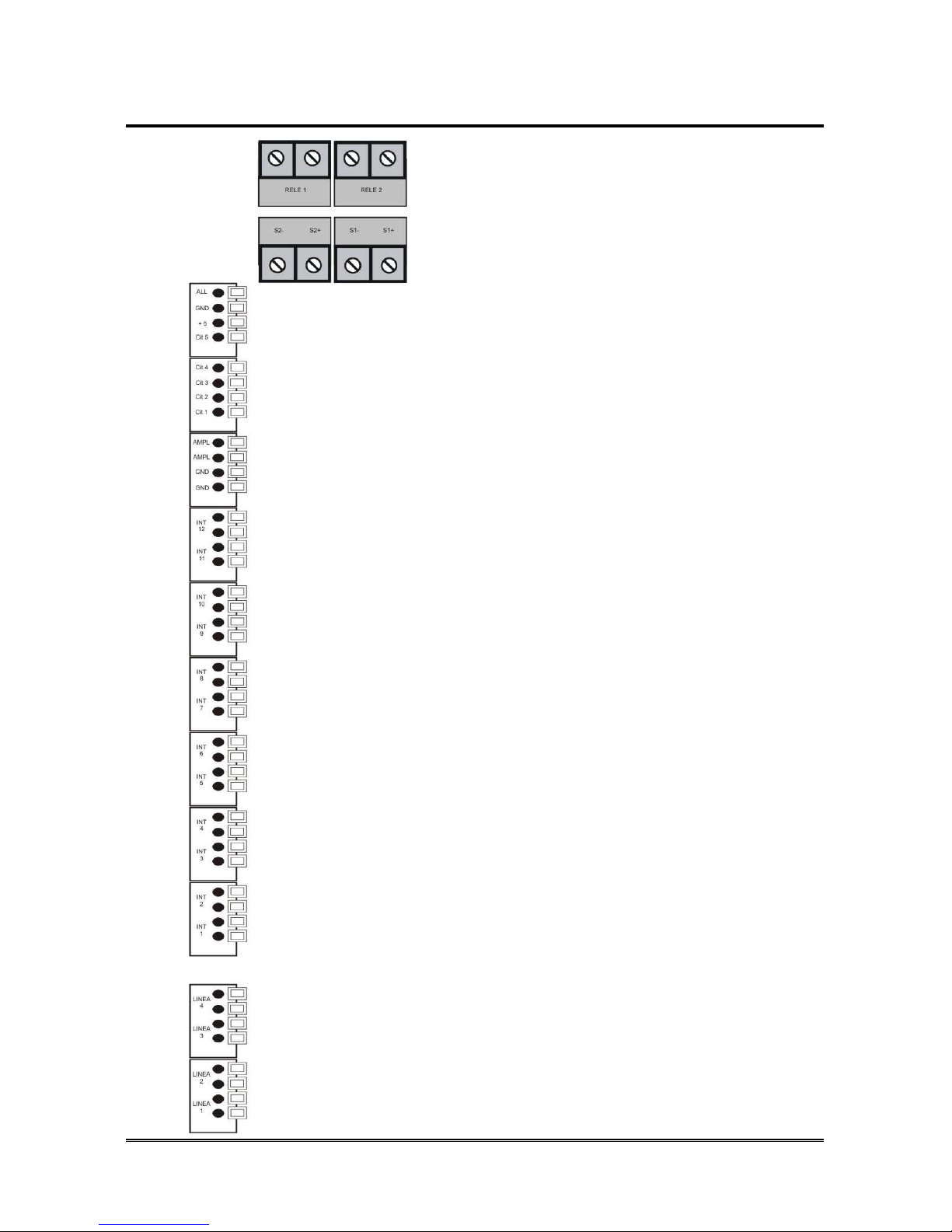
Terminals
Relay 1: Relay 1 terminals
Relay 2: Relay 2 terminals
S2 –: “–“ signals terminal (extensions 7~12)
S2 +: “+“ signals terminal (extensions 7~12)
S1 –: “–“ signals terminal (extensions 1~6)
S1 +: “+“ signals terminal (extensions 1~6)
ALL: Alarm input
+ 5: Common for Alarm input
Cit 5: Doorphone call 2
Cit 4: Doorphone call 1
Cit 3: Doorphone common terminal
Cit 2: Doorphone speech output
Cit 1: Doorphone speech input
AMPL: Amplifier exit
GND: Not used
INT 12: Extension 12 terminals
INT 11: Extension 11 terminals
INT 10: Extension 10 terminals
INT 9: Extension 9 terminals
INT 8: Extension 8 terminals
INT 7: Extension 7 terminals
INT 6: Extension 6 terminals
INT 5: Extension 5 terminals
INT 4: Extension 4 terminals
INT 3: Extension 3 terminals
INT 2: Extension 2 terminals
INT 1: Extension 1 terminals
Linea 4: Analogue line 4 terminals
Linea 3: Analogue line 3 terminals
Linea 2: Analogue line 2 terminals
Linea 1: Analogue line 1 terminals

HI-PRO 280 Pagina 15
LEDs
Hi-Pro 280 has 4 LEDs which are visible from outside the cabinet:
Electric mains Power Supply
Device status
Computer connection
Profile in use
Led Status
Power supply
OFF: mains absent
ON: mains present
Device status Flash: regular operation
Computer connection ON: Computer connected to Hi-Pro
Profile in use
OFF: DAY profile
ON: NIGHT profile
Flash: CUSTOM profile
DIP switches
The correct position of the switches is shown in the figure below:

Pagina 16 HI-PRO 280
HI-PRO 280 INSTALLATION
The following connections must be provided:
• connection to a 230 Vac power supply socket
• connection to external telephone networks, if needed
• connection of BCA (analogue standard) telephones
• connection of ST 600 Personal Phone system telephones
• connection of doorphone, if any
• connection of actuator relays, if any
• connection of digital inputs, if any.
Recommendations
- Do not install Hi-Pro near other electronic or magnetic devices, since they
could be affected by RF interferences coming from the device.
- Do not lay the telephone cables near the 230 Vac mains.
- We recommend connecting the telephones to Hi-Pro using a twisted pair
cable. Use multi-pair cables only when absolutely inevitable (and, in any case,
never more than 20 m long).
Operations to perform
Drill two 5 mm diameter holes on the wall, 6 cm apart and screw the
bracket.
Place Hi-Pro on the bracket and make it slide
Loosen the right lateral part of the lid and rotate it downwards.
Connecting the external lines
Connect, if present, the external lines to the analogue lines terminals
(see Terminals page Errore. Il segnalibro non è definito.).
Connecting internal telephones
Connecting ST 600 Personal Phone system telephones
Up to 8 system telephones can be connected to Hi-Pro .
ST 600 telephones allow knowing the status of the external lines and the
extensions, making the use easier. Moreover, they are interfaceable with the
PC.
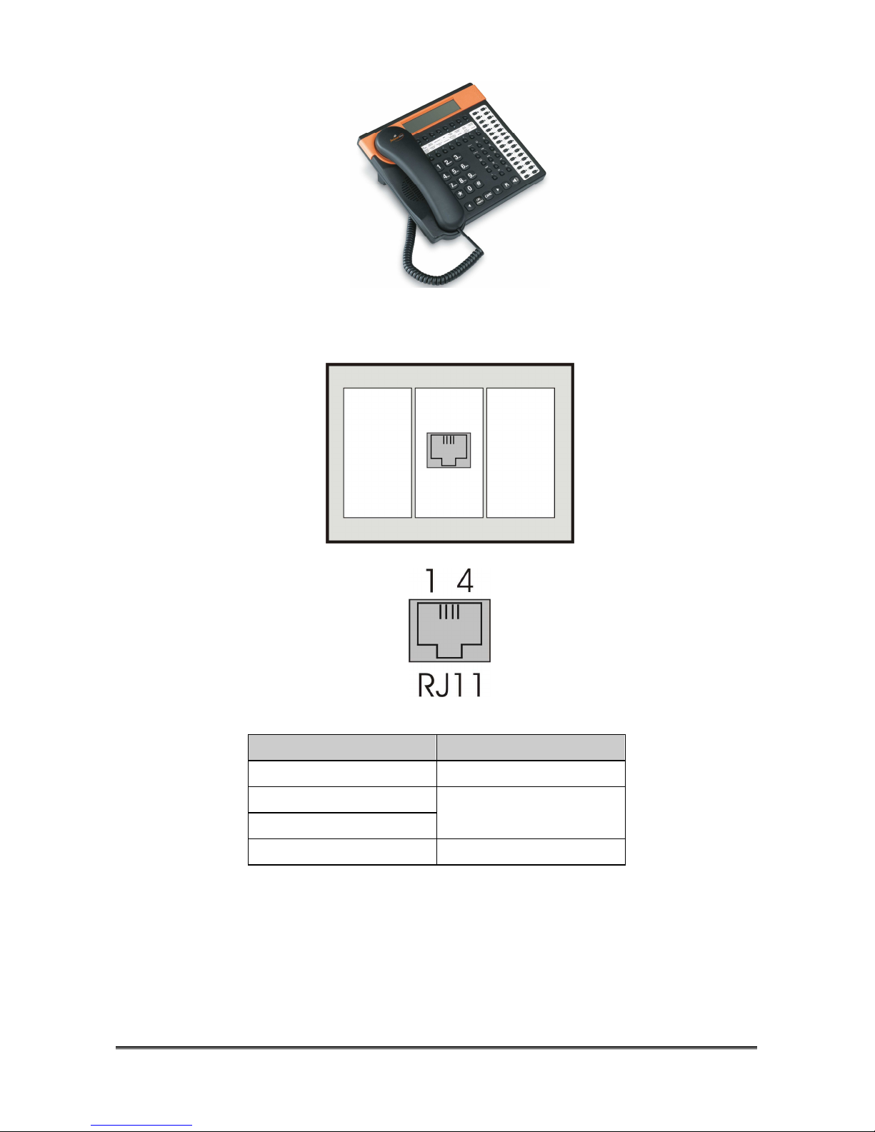
HI-PRO 280 Pagina 17
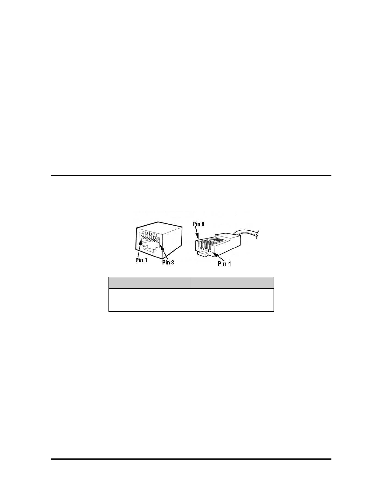
Preparing the connection of ST 600 Personal Phone system telephones, RJ11
sockets must be provided, and wiring must be made with a 2-pair cable.
Plug RJ11 6/4 ST 600
Pin 1
S +
Pin 2 Numbered
terminal
Pin 3
Pin 4
S -
When a system telephone is connected to the Hi-Pro terminal board, the first
pair (Pin 2-3) must be connected to the terminal marked with the number of the
extension to be connected; the second pair (Pin 1-4, power supply and signals
terminals) must be connected to the “S+/S-” terminals, paying attention on the
polarity. Specifically “S1+/S1-“ terminals are intended to extensions 1~6, while
“S2+/S2-“ terminals are intended to extensions 7~12).
Pagina 18 HI-PRO 280
Connecting BCA (analogue) telephones
When connecting BCA telephones, it is sufficient to provide for the passage of
the cable to one pair. The pair (Pin 2-3) must be connected to the terminal
marked with the number of the extension to be connected.
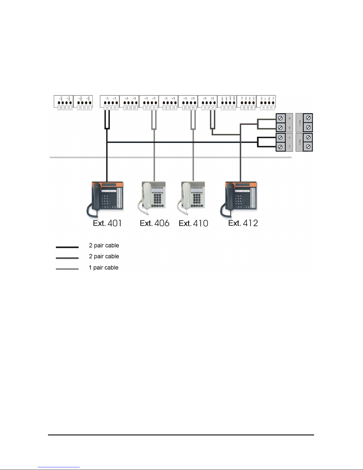
Connection example
Connect the telephones.
Start-up
Reposition the lateral part of the lid.
Connect mains cable to power supply.
This way, Hi-Pro is operative and ready to be programmed and used.
Switch-off
Disconnect the power supply cable.

HI-PRO 280 Pagina 19
A
CCESSORY CONNECTIONS
PSTN (analogue lines) optional board
With the PSTN optional board (2 external lines and 4 extensions), it is possible
to extend the Hi-Pro 280 up to 4 analogue lines and 12 extensions.
Installation
Disconnect Hi-pro from the mains.
Unhook the right side of the lid and turn it down.
Open the remaining part of the lid unfastening the screw on top and
turn it down.
Remove jumpers in JP3 (H in picture page 13).
Insert the optional board in connectors: JP1, JP2, JP3, JP5 and JP9
making sure that all the pins are inserted into the slots.
Reassemble the main part of the lid and tighten the screw.
Replace the right side of the lid .
Connect the mains.
ISDN optional board
With the ISDN optional board (2BRI – 4 extensions – doorphone), it is possible
to extend the Hi-Pro 280 up to 2 BRI and 12 extensions.
Note: with ISDN board it is possible to configure the system for 2
BRI or 2 analogue lines and 1 BRI.
This board it is also integrated with a doorphone interface for the connection of
traditional doorphone systems (4/5 wires). The interface manages 2 ringer
inputs and 1 speech input.
If the optional board is inserted, relays 1 and 2 are automatically assume the
function of a door opener (door 1 and door 2 respectively), but they may also
be used as actuators.
Note: relays 1 and 2 can command loads with up to 10A to 24V
absorption.
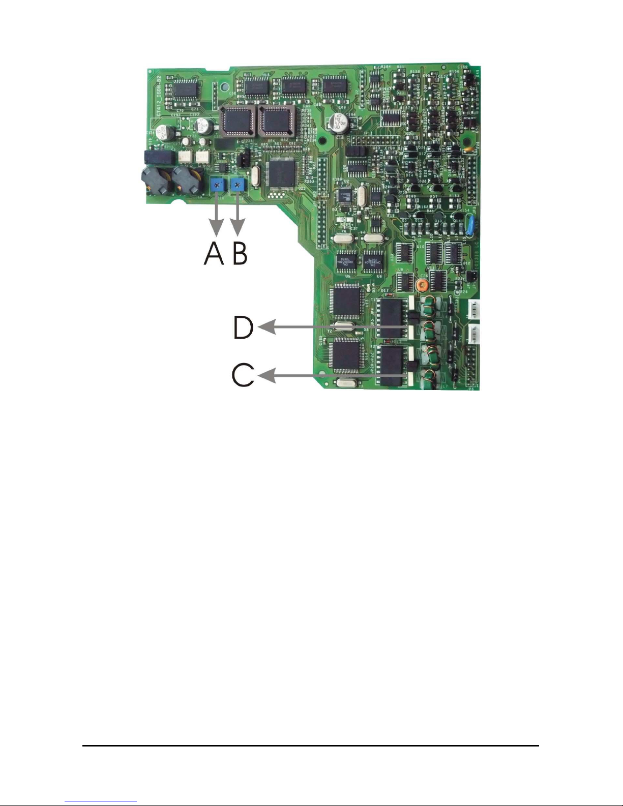
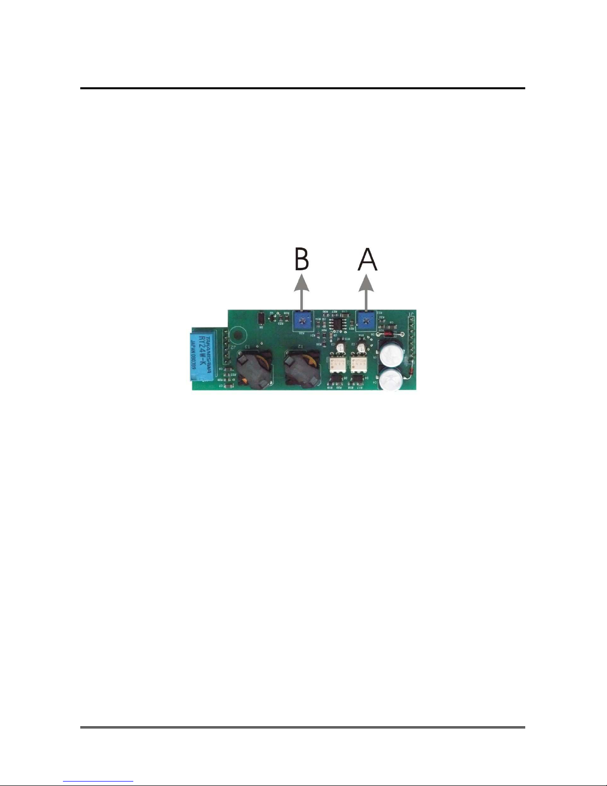
Pagina 20 HI-PRO 280
A Input volume adjusting trimmer (from doorphone to telephone)
B Output volume adjusting trimmer (from telephone to doorphone)
C Bus ISDN T01 termination jumpers (resistance)
D Bus ISDN T02 termination jumpers (resistance)
Installation
Disconnect Hi-pro from the mains.
Unhook the right side of the lid and turn it down.
Open the remaining part of the lid unfastening the screw on top and
turn it down.
Remove jumpers in JP3 (H in picture page 13).
Insert the optional board in connectors: JP1, JP2, JP3, JP5 and JP9
making sure that all the pins are inserted into the slots.
If necessary remove bus termination jumpers (C and D in previous fig.).
Note: the termination resistances must be inserted only in the last
plug of the bus.
Reassemble the main part of the lid and tighten the screw.
Replace the right side of the lid .
Connect the mains.
HI-PRO 280 Pagina 21
Doorphone optional board
The Doorphone optional board allows to interface Hi-Pro 280 with a
traditional doorphone (4/5 wires doorphones). The board manages 2 ringer
inputs and 1 speech input.
If the optional board is inserted, relays 1 and 2 are automatically assume the
function of a door opener (door 1 and door 2 respectively), but they may also
be used as actuators.
Note: relays 1 and 2 can command loads with up to 10A to 24V
absorption.
A Input volume adjusting trimmer (from doorphone to telephone)
B Output volume adjusting trimmer (from telephone to doorphone)
Installation
Disconnect Hi-pro from the mains.
Unhook the right side of the lid and turn it down.
Open the remaining part of the lid unfastening the screw on top and
turn it down.
Insert the doorphone board in the related connectors as shown in figure
at page 13 (D).

Pagina 22 HI-PRO 280
Doorphone connection
Cit 1: Speech input
Cit 2: Speech output
Cit 3: Common
Cit 4: Ringer 1
Cit 5: Ringer 2
Connect the doorphone station to the corresponding contacts in
the terminal.
Connect the door openers to relays terminals (Relay 1 and Relay 2
terminals).
Connect the mains.
Power on doorphone station.
Check audio levels, if necessary use trimmers on the doorphone or ISDN
board.
Reassemble the main part of the lid and tighten the screw.
Replace the right side of the lid .
Actuator Relays
Hi-Pro has 2 relay which can command loads with up to 10A to 24V
absorption. For Relays configuration use teleprogramming software or
programming codes at page 108.
Note: if the doorphone or ISDN optional board is inserted, relays 1
and 2 are automatically assume the function of a door opener
(door 1 and door 2 respectively), but they may also be used as
actuators dialling the related code.
HI-PRO 280 Pagina 23
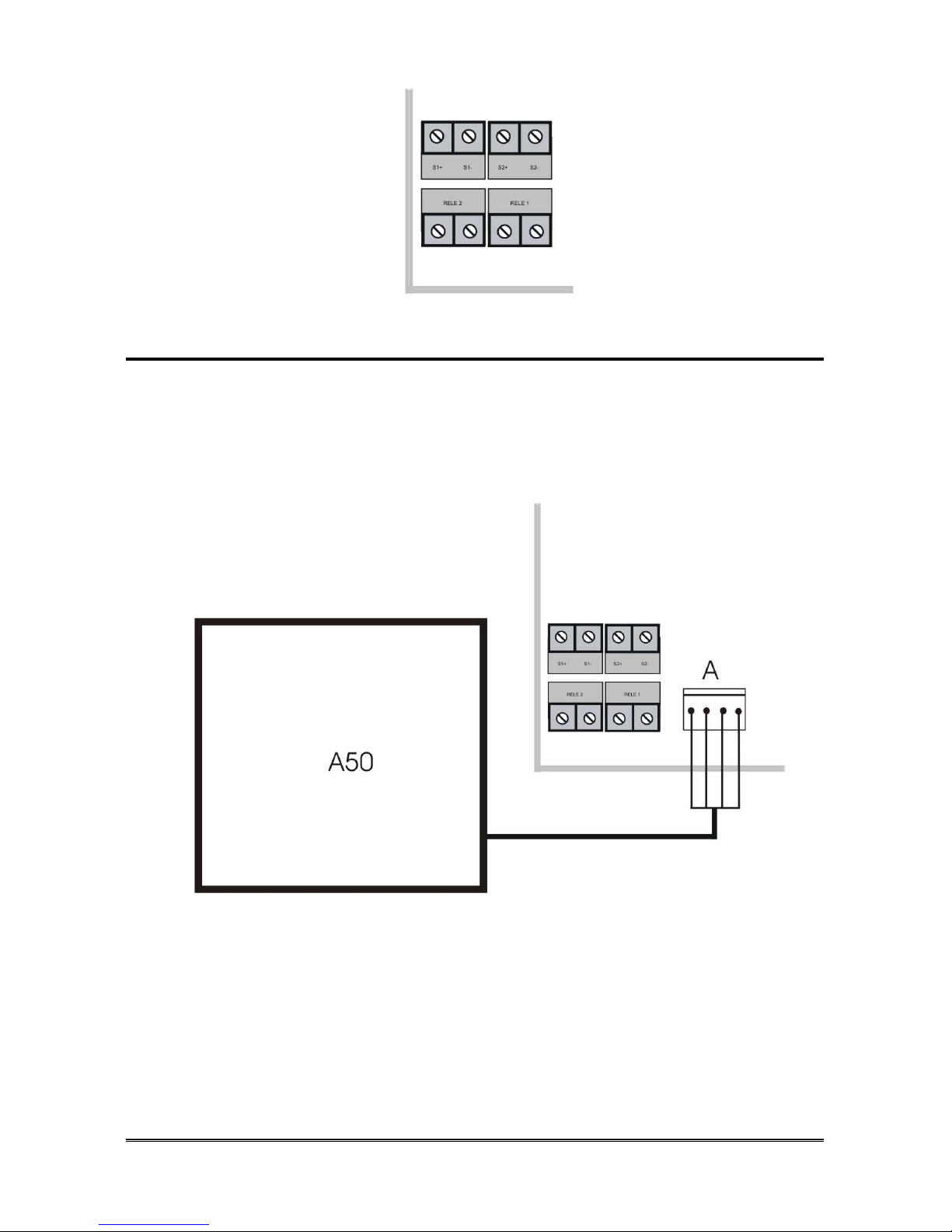
External Music on-hold source
Hi-Pro is projected for the connection of an external music source, which may
be used both as music on-hold and as background music for Responder, DISA
and Voicemail messages.
Esse-ti external source: A50
A: A50 connector
Disconnect Hi-pro from the mains.
Unhook the right side of the lid and turn it down.
Connect A50 in its connector (E in figure page 13).
Replace the right side of the lid and connect the mains.
Note: for activation, please refer to the programming paragraph
“External music source”.
Pagina 24 HI-PRO 280
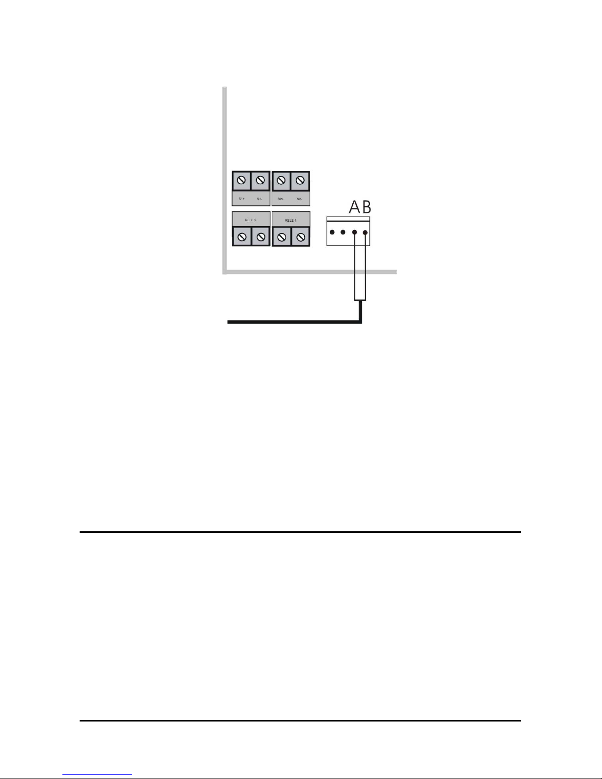
Other music sources
A: Aux
B: Ground
Disconnect Hi-pro from the mains.
Unhook the right side of the lid and turn it down.
Connect music source in its connector (E in figure page 13) as shown in
previous figure.
Replace the right side of the lid and connect the mains.
Note: for activation, please refer to the programming paragraph
“External music source”.
Amplifier
Hi-Pro can be connected to an external amplifier, to be used as a pager. The
amplifier must be provided with an AUX input with volume control.
Disconnect Hi-pro from the mains.
Unhook the right side of the lid and turn it down.
Using an appropriate shielded cable, connect amplifier input to AMPL
connector on the terminal. The connection has no polarity.
Replace the right side of the lid and connect the mains.
Note: for activation, please refer to the programming paragraph
“Amplifier”.
HI-PRO 280 Pagina 25
Note: activating the Amplifier on Hi-Pro 412 will deactivate last
extension.
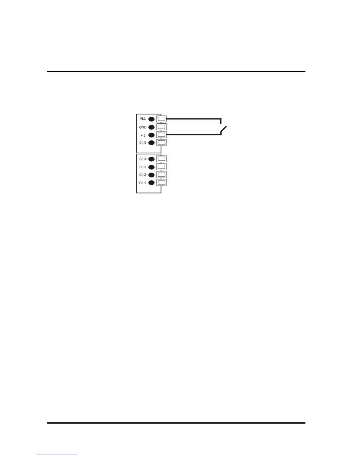
Digital Input
Hi-Pro in equipped with a digital input (ALL) customizable as “normally
closed” or “normally open”. Configuration and use are possible only by
teleprogramming software.
Connect a pushbutton switch between the +5 contact and the ALL
contact.

Pagina 26 HI-PRO 280
CONNECTION TO THE
PC
Hi-Pro can be connected to a PC via USB port, to access programming (with
teleprogramming software) or to acquire informations about incoming/outgoing
calls stored in the buffer memory (with a terminal emulation utility, e.g.: Hyper
Terminal).
Using a USB cable, connect the Hi-pro USB port to a USB port of the PC.
In case of driver installation request, follow the instructions and search
for drivers in CD-ROM drivers folder (supplied with Hi-Pro).
If a terminal emulation utility/program is used, the following parameters
must be set up:
Bit per second 115200
Parity None
Data Bits 8
Stop Bits 1
Flow control None

HI-PRO 280 Pagina 27
W
ORKING IN EMERGENCY MODE
In case of mains supply absence, Hi-Pro 280 and Hi-Pro 412 rack (only
analogue external lines) work as the following emergency mode:
- extension 401 can call and receive from external line 01;
- extension 402 can call and receive from external line 02;
- extension 409 can call and receive from external line 03;
- extension 410 can call and receive from external line 04.
In Hi-Pro 280 hybrid version (1BRI and 2 analogue lines) emergency mode
works in the following way:
- extension 401 can call and receive from external line 01;
- extension 402 can call and receive from external line 02.
If using Hi-Pro 280 or Hi-Pro 412 ISDN rack only with ISDN lines, emergency
mode is not available.
M
AINTENANCE
There are no parts of the product that need maintenance or that can be replaced
by the user in case of damage.
In case of faults, please contact our technical servicing department.
Pagina 28 HI-PRO 412 RACK (ISDN)
HI-PRO 412 RACK (ISDN)
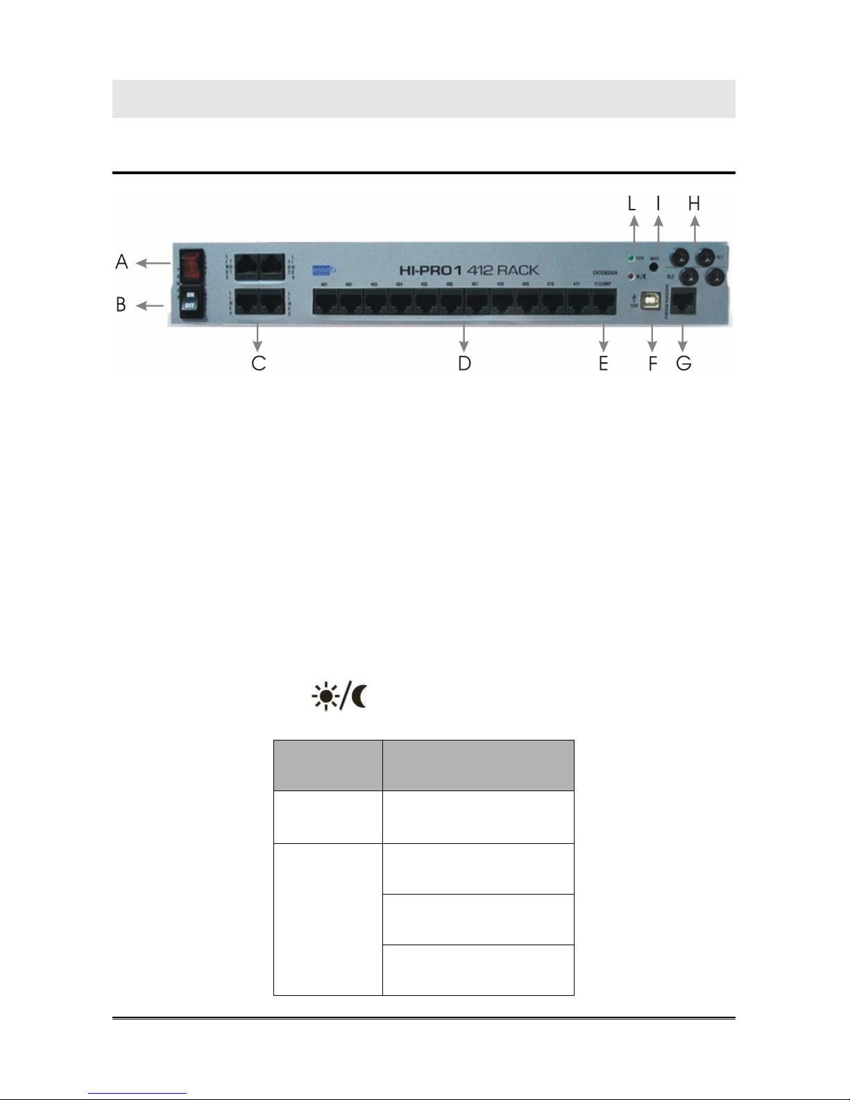
Front panel description
A 230V~ mains switch
B Optional batteries switch
C L01~L04, T01~T02 jack
D Extensions 401~411 jack
E Extension 412 or amplifier jack
F USB Port for pc connection
G Doorphone jack
H Relay inputs (banana connectors)
I External music source Input
L LED
RUN Device status
Profile in use
LED Status
Device status
Flash: regular operation
Profile in use
Off: DAY profile
On: NIGHT profile
Flash: CUSTOM profile
HI-PRO 412 RACK (ISDN) Pagina 29
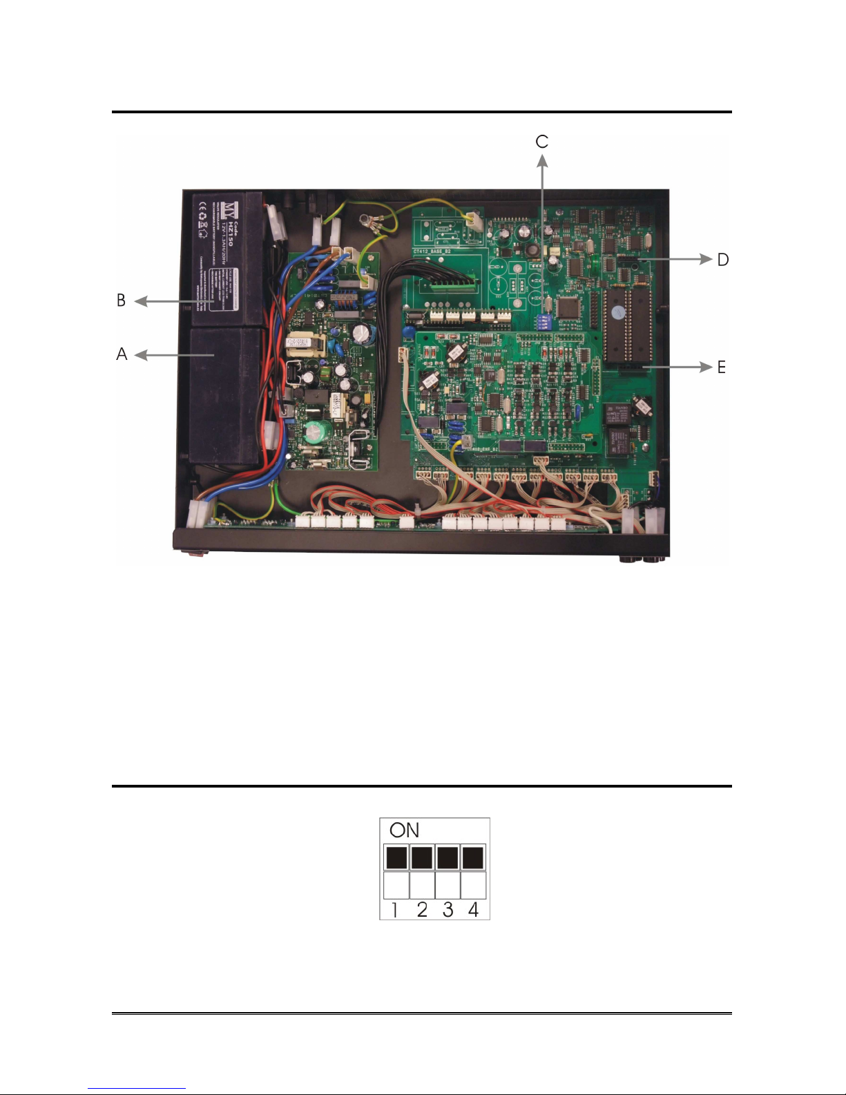
Hardware description
A Battery ( 12V 1,3A/h)
B Battery ( 12V 1,3A/h)
C DIP switches
D Optional Doorphone board connector (analogue equipement)
E Optional Doorphone board connector (analogue equipement)
F Esse-Ti A50 connector
DIP switches
The correct position of the switches is shown in the figure below:
Pagina 30 HI-PRO 412 RACK (ISDN)
HI-PRO 280 RACK (ISDN) INSTALLATION
The following connections must be provided:
• connection to a 230 Vac power supply socket
• connection to external telephone networks, if needed
• connection of BCA telephones
• connection of ST 600 Personal Phone system telephones
• connection of doorphone, if any
• connection of actuator relays, if any
• connection of digital inputs, if any.
Recommendations
- Do not install Hi-Pro Rack (ISDN) near other electronic or magnetic devices
if they were not designed to be combined with it.
- Do not lay the telephone cables near the 230 Vac mains.
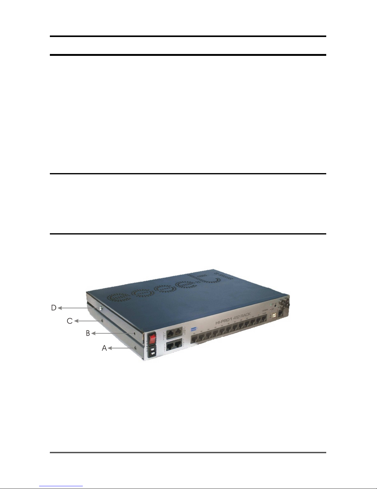
Installation
Hi-Pro 412 Rack (ISDN) can be installed in a rack cabinet or wall-mounted
using mounting brackets supplied with PBX.
Rack installation
Remove the 3 screws shown as A, B and C in previous figure and the
other 3 on the opposite side.
Apply the rack mounting brackets to Hi-Pro 412 Rack (ISDN).
Fix the brackets by tightening the screws previously removed.
Fix Hi-Pro 412 Rack (ISDN) to the rack cabinet.
HI-PRO 412 RACK (ISDN) Pagina 31
Wall mounting
Follow the instructions of the optional brackets.
Operations to perform
External lines connection
Connect external lines to the RJ45/RJ11 connectors located in Hi-Pro
412 Rack (ISDN) (C in figure page 28).
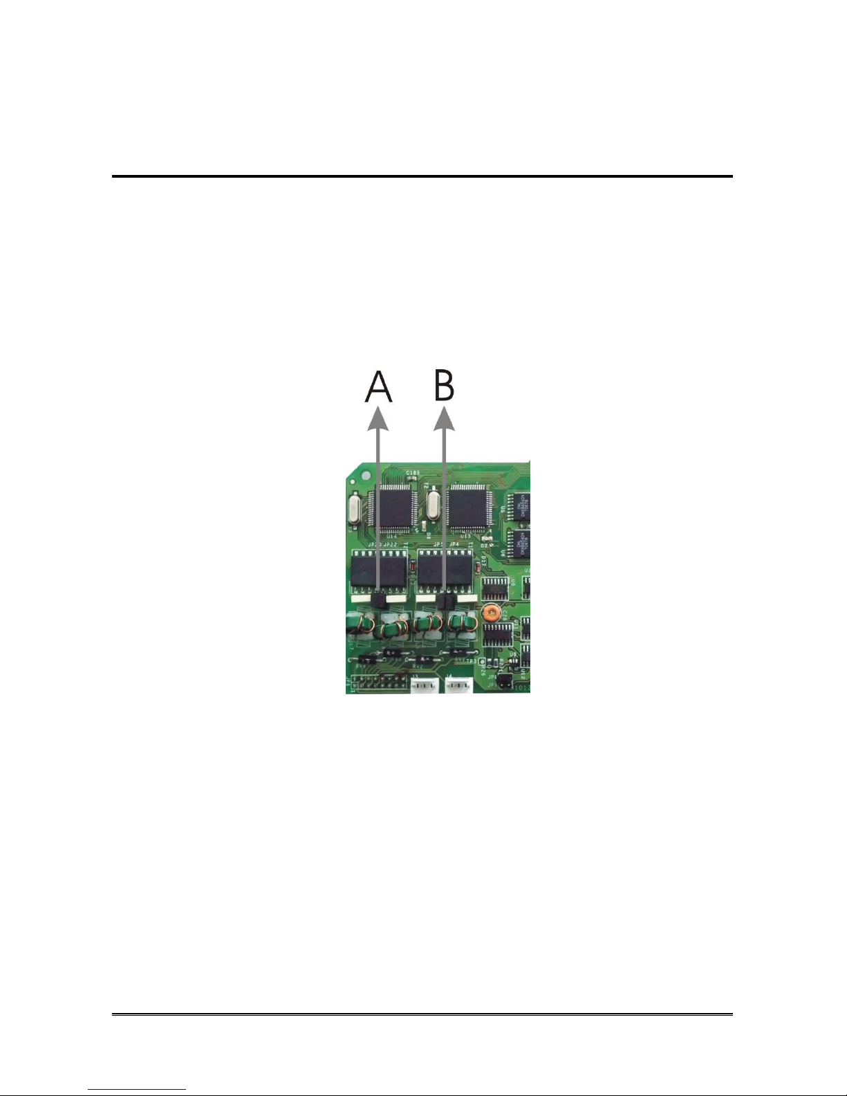
If necessary remove bus termination jumpers (resistance), in case of
ISDN lines (A and B in figure below).
Note: the termination resistances must be inserted only in the last
plug of the bus.
.
A Bus ISDN T01 termination jumpers (resistance)
B Bus ISDN T02 termination jumpers (resistance)
Connecting internal telephones
Connecting ST 600 Personal Phone system telephones
Up to 8 system telephones can be connected to 412 Rack (ISDN). ST 600
telephones allow knowing the status of the external lines and the extensions,
making the use easier. Moreover, they are interfaceable with the PC.

Pagina 32 HI-PRO 412 RACK (ISDN)
When preparing the connection of ST 600 Personal Phone system telephones,
use Category 5 straight cable from Hi-Pro 412 Rack (ISDN) to Patch Panel.
System telephones connection require a 2-pair cable, one pair for data (pin 3
with positive polarity and pin 6 with negative polarity) and the other for the
speech (pin 4/5).
Plug RJ45 ST 600
Pin 3
Segn. +
Pin 4
Numbered
terminal
Pin 5
Pin 6
Segn. -
Connect extension to RJ45/RJ11 jacks present on Hi-Pro 412 Rack
(ISDN) front panel (D in figure page 28).
Connect system telephones to the RJ45 jacks arranged in the various
environments using the inverted plug-plug cable supplied with
telephone.
Connecting BCA telephones
Connect BCA telephones requires a single pair (pin 4/5).
Connect extension to RJ45/RJ11 jacks present on Hi-Pro 412 Rack
(ISDN) front panel (D in figure page 28).
Connect BCA telephones to the RJ45 jacks arranged in the various
environments.
Starting
Connect power supply cable to Hi-Pro 412 Rack (ISDN).

HI-PRO 412 RACK (ISDN) Pagina 33
Connect the plug to the mains.
Turn on the mains switch and the battery switch (if any).
Hi-Pro Rack (ISDN) is now working and ready to be programmed and used.
Hi-pro can't start by turning on battery switch only.
Switch-off
Turn off the mains switch and the battery switch (if any).
O
PTIONAL CONNECTIONS
Batteries
It is possible to connect 2 back-up batteries (12V 1,3A/h rechargeable) to HiPro 412 Rack (ISDN) in order to ensure the functioning of the
product in case of power failures.
In case of mains supply absence, Hi-Pro 412 Rack work as the following
emergency mode:
Working batteries
PBX works normally as in presence of power supply;
Not Working batteries
PBX allows following operations:
- extension 401 can call and receive from external line 01;
- extension 402 can call and receive from external line 02;
- extension 409 can call and receive from external line 03;
- extension 410 can call and receive from external line 04.
In case of mains supply absence, Hi-Pro 412 ISDN Rack work as the following
emergency mode:
Working batteries
PBX works normally as in presence of power supply;
Not Working batteries
No operations available with PBX.
Installation
Remove the 2 screws shown as B and D in figure page 30 and the other
2 on the opposite side.
Remove Hi-Pro 412 Rack (ISDN) cover by sliding towards the rear.

Pagina 34 HI-PRO 412 RACK (ISDN)
Using faston cables supplied with batteries, connect batteries in series
and then to Hi-Pro 412 Rack (ISDN).
Place batteries in battery compartments (A and B in figure page 29).
Replace the cover.
Tighten the screws removed before.
Optional o Integrated Doorphone Board
Hi-Pro 412 ISDN Rack
Hi-Pro 412 ISDN Rack has a built-in doorphone board for interfacing to the
most common doorphone systems (traditional 4/5 wire doorphones). The
Doorphone board is equipped with 2 ringer inputs and 1 speech input.
In Hi-Pro 412 ISDN Rack, relays 1 and 2 assume the function of a door opener
(door 1 and door 2 respectively), but they may also be used as actuators.
Note: relays 4 and 5 can command loads with up to 10A to 24V
absorption.
A Input volume adjusting trimmer (from doorphone to telephone)
B Output volume adjusting trimmer (from telephone to doorphone)
Hi-Pro 412 Rack
Hi-Pro 412 Rack can be interfaced with the most common doorphone systems
(4/5 wires doorphones) thanks to the optional Doorphone board. The board
manages 2 ringer inputs and 1 speech input.
If the optional board is inserted, relays 1 and 2 are automatically assume the
function of a door opener (door 1 and door 2 respectively), but they may also
be used as actuators.
Note: relays 1 and 2 can command loads with up to 10A to 24V
absorption.

HI-PRO 412 RACK (ISDN) Pagina 35
A Input volume adjusting trimmer (from doorphone to telephone)
B Output volume adjusting trimmer (from telephone to doorphone)
Remove the 2 screws shown as B and D in figure page 30 and the other
2 on the opposite side.
Remove Hi-Pro 412 Rack cover by sliding towards the rear.
Insert the doorphone board in the related connectors (D and E page
29).
Connecting Doorphone
Plug RJ45 DOORPHONE
Pin 1
Ringer 2
Pin 2
Ringer 1
Pin 3
Common terminal
Pin 4
Speech output
Pin 5
Speech input
Arrange a RJ45 plug (according to the instructions given in the
table above) at the end of the cable used to connect the door phone.
Using the cable prepared, connect the doorphone station to RJ45
DOORPHONE jack on Hi-Pro 412 Rack (ISDN) front panel (G in figure
page 28).

Pagina 36 HI-PRO 412 RACK (ISDN)
Switch on PBX.
Power on doorphone station.
Check audio levels, if necessary use trimmers on the optional (or
integrated) doorphone board.
Replace the cover.
Tighten the screws removed before.

HI-PRO 412 RACK (ISDN) Pagina 37
Actuator relays
Hi-Pro has 2 actuator relays to command loads with up to 10A to 24V
absorption. Use the remote programmer software or the programming codes at
page Errore. Il segnalibro non è definito. to configure the relays.
Note: if the doorphone or ISDN optional board is inserted, relays 1
and 2 are automatically assume the function of a door opener
(door 1 and door 2 respectively), but they may also be used as
actuators dialling the related code.
Connect the door opener mechanisms to the relay contacts (inputs H in
figure page 28) using banana connectors supplied with Hi-Pro.
External Music source
Hi-Pro is projected for the connection of an external music source, which may
be used both as music on-hold and as background music for Responder, DISA
and Voicemail messages.
Esse-ti external source: A50
Remove the 2 screws shown as B and D in figure page 30 and the other
2 on the opposite side.
Remove Hi-Pro 412 Rack (ISDN) cover by sliding towards the rear.
Remove the cable inserted in A50 connector (F in figure page 29) and
connect A50.
Replace the cover.
Tighten the screws removed before.
Note: for activation, please refer to the programming paragraph
“External music source”.
Other music sources
Connection must be realized with the mini-jack supplied with PBX.
Pagina 38 HI-PRO 412 RACK (ISDN)
Loosen the mini-jack and insert properly the two wires of your external
music source within the plastic.
Connect the AUDIO wire to the flap of the mini-jack labelled A in the
figure above.
Connect the GND wire to the flap of the mini-jack labelled B in the figure
above.
Refit the mini-jack.
Connect mini-jack to Hi-Pro 412 Rack (ISDN) music source input (I in
figure page 28).
Note: for activation, please refer to the programming paragraph
“External music source”.
Amplifier
Hi-Pro can be connected to an external amplifier, to be used as a pager. The
amplifier must be provided with an AUX input with volume control.
Plug RJ45 412/AMP
Pin 1
Amplifier
Pin 2
Amplifier
Arrange a RJ45 plug (according to the instructions given in the
table above) at the end of the cable used to connect the amplifier.
Using the cable prepared, connect the amplifier to RJ45 amplifier jack on
Hi-Pro 412 Rack (ISDN) front panel (E in figure page 28).
Note: for activation, please refer to the programming paragraph
“Amplifier”.
Note: activating the Amplifier on Hi-Pro 412 will deactivate last
extension.

HI-PRO 412 RACK (ISDN) Pagina 39
Digital input
Hi-Pro in equipped with a digital input (ALL) customizable as “normally
closed” or “normally open”. Configuration and use are possible only by
teleprogramming software.
Plug RJ45 DOORPHONE
Pin 6
+5V reference voltage
for alarm input
Pin 8
Alarm input
Arrange a RJ45 plug (according to the instructions given in the
table above) at the end of the cable used to connect a pushbutton
switch.
Connect the cable prepared to RJ45 Doorphone jack on Hi-Pro 412 Rack
(ISDN) front panel (G in figure page 28).

Pagina 40 HI-PRO 412 RACK (ISDN)
C
ONNECTION TO THE
PC
Hi-Pro can be connected to a PC via USB port, to access programming (with
teleprogramming software) or to acquire informations about incoming/outgoing
calls stored in the buffer memory (with a terminal emulation utility, e.g.: Hyper
Terminal).
Using a USB cable, connect the Hi-pro USB port to a USB port of the PC.
In case of driver installation request, follow the instructions and search
for drivers in CD-ROM drivers folder (supplied with Hi-Pro).
If a terminal emulation utility/program is used, the following parameters
must be set up:
Bit per second 115200
Parity None
Data Bits 8
Stop Bits 1
Flow control None
M
AINTENANCE
Except for the backup batteries (if any), there are no parts of the product that
need maintenance or that can be replaced by the user in case of damage.
In case of faults, please contact our technical servicing department .

Programmings to be performed during installation phase Pagina 41
PROGRAMMINGS TO BE PERFORMED
DURING INSTALLATION PHASE
S
ETTING A DEFAULT CONFIGURATION
A default configuration is given by a set of programmings through which it is
possible to establish the basic operation of the system.
Hi-Pro has seven default configurations, which can be recalled by a single
programming code:
• DEFAULT: factory configuration;
• HOME: for Hi-Pro home installation;
• HOME /OFFICE: for Hi-Pro home/office installation;
• OFFICE: for Hi-Pro office installation.
• OFFICE with DEDICATED FAX LINE: for Hi-Pro office installation;
• OFFICE with DEDICATED GSM LINE: for Hi-Pro office installation;
• OFFICE with DEDICATED GSM and FAX LINE: for Hi-Pro office
installation (only for 4 lines equipped Hi-Pro).
Each configuration can be modified or customised
at any time using programming codes.
Default
DEFAULT configuration provides for:
- under any profile, all telephones will ring in event of incoming call;
- premium rate call barring (e.g. 144-166-899);
- time bands inactive;
- call forwarding towards a number to be programmed is enabled for
doorphone calls;
- call forwarding towards a number to be programmed is enabled for
incoming external calls;
Home
HOME configuration provides for:
- the automatic engagement of the external line for all extensions (it is not
necessary to dial 0);
- premium rate call barring (e.g. 144-166-899);
- time bands inactive;

Pagina 42 Programmings to be performed during installation phase
- DAY profile
. under any profile, all telephones will ring in event of incoming
call;
- NIGHT profile
. all telephones will ring in event of incoming call;
. call forwarding towards a number to be programmed is enabled
for doorphone calls;
. call forwarding towards a number to be programmed is enabled
for incoming external calls;
- CUSTOM profile
. only first extension (401) will ring in event of incoming call
(making exception for VIP calls);
Home/Office
HOME/OFFICE configuration provides for:
- a different allocation of the lines between home and office:
. home: line L01, extensions 401~404, doorphone 1;
. office: lines L02~L04, extensions 405~412, doorphone 2;
- premium rate call barring (e.g. 144-166-899);
- time bands work this way: DAY profile: from 8 to 12 a.m. and from 2 to 6
p.m., NIGHT profile: in the remaining hours of the day and on Saturday
and Sunday;
- automatic switch-FAX enabled (FAX extension: 408; automatic line
engagement for this extension);
- DAY profile
. home extensions will ring in event of incoming call from L01,
while first office extension(405) will ring in event of incoming
call from L02~L04, other office extensions will ring with a
time-delay;
. courtesy responder enabled on lines L02~L04, with the message
“we are busy at the moment, please hold the line”;
- NIGHT profile
. home extensions will ring in event of incoming call from L01,
while office extensions will ring in event of incoming call from
L02~L04;
. call forwarding towards a number to be programmed is enabled
for doorphone calls;
. call forwarding towards a number to be programmed is enabled
for incoming external calls;

Programmings to be performed during installation phase Pagina 43
. courtesy responder enabled on lines L02~L04, with the message
“we are absent, please kindly phone back”;
- CUSTOM profile
. home extensions will ring in event of incoming call from L01,
while office extensions will ring in event of incoming call from
L02~L04;
. courtesy responder enabled on lines L02~L04, with the message
“we are absent, please kindly phone back”;
Office
OFFICE configuration provides for:
- premium rate call barring (e.g. 144-166-899);
- time bands work this way: DAY profile: from 8 to 12 a.m. and from 2 to 6
p.m., NIGHT profile: in the remaining hours of the day and on Saturday
and Sunday;
- automatic switch-FAX enabled (FAX extension: 408; automatic line
engagement for this extension);
- DAY profile
. first extension (401) will ring in event of incoming call, while
all other extensions will ring with a time-delay;
. courtesy responder enabled with the message “we are busy at
the moment, please hold the line”;
- NIGHT profile
. all telephones will ring in event of incoming call;
. call forwarding towards a number to be programmed is enabled
for doorphone calls;
. call forwarding towards a number to be programmed is enabled
for incoming external calls;
. courtesy responder enabled with the message “we are absent,
please kindly phone back”;
- CUSTOM profile
. all telephones will ring in event of incoming call;
. courtesy responder enabled with the message “we are absent,
please kindly phone back”;
Office with dedicated FAX line
OFFICE with dedicated FAX line configuration provides for:
- last defined line (L02 or L04, depending on PBX equipment) is dedicated
for FAX receiving and it’s used for last in event of outgoing call;

Pagina 44 Programmings to be performed during installation phase
- FAX extension: 408; automatic line engagement for this extension;
automatic switch-FAX disabled;
- premium rate call barring (e.g. 144-166-899);
- time bands work this way: DAY profile: from 8 to 12 a.m. and from 2 to 6
p.m., NIGHT profile: in the remaining hours of the day and on Saturday
and Sunday;
- DAY profile
. first extension (401) will ring in event of incoming call, while
all other extensions will ring with a time-delay;
. courtesy responder enabled with the message “we are busy at
the moment, please hold the line”;
- NIGHT profile
. all telephones will ring in event of incoming call;
. call forwarding towards a number to be programmed is enabled
for doorphone calls;
. call forwarding towards a number to be programmed is enabled
for incoming external calls;
. courtesy responder enabled with the message “we are absent,
please kindly phone back”;
- CUSTOM profile
. all telephones will ring in event of incoming call;
. courtesy responder enabled with the message “we are absent,
please kindly phone back”;
OFFICE with dedicated GSM line
OFFICE with dedicated GSM line configuration provides for:
- last defined line (L02 or L04, depending on PBX equipment) is dedicated
for GSM calls;
- L.C.R. service automatically routes GSM calls via GSM dedicated line
(L02 or L04);
- premium rate call barring (e.g. 144-166-899);
- time bands work this way: DAY profile: from 8 to 12 a.m. and from 2 to 6
p.m., NIGHT profile: in the remaining hours of the day and on Saturday
and Sunday;
- DAY profile
. first extension (401) will ring in event of incoming call, while
all other extensions will ring with a time-delay;
. courtesy responder enabled with the message “we are busy at
the moment, please hold the line”;

Programmings to be performed during installation phase Pagina 45
- NIGHT profile
. all telephones will ring in event of incoming call;
. call forwarding towards a number to be programmed is enabled
for doorphone calls;
. call forwarding towards a number to be programmed is enabled
for incoming external calls;
. courtesy responder enabled with the message “we are absent,
please kindly phone back”;
- CUSTOM profile
. all telephones will ring in event of incoming call;
. courtesy responder enabled with the message “we are absent,
please kindly phone back”;
OFFICE with dedicated FAX line and GSM line
(only 4 lines equipments)
Office with dedicated FAX line and GSM line configuration provides for:
- line L03 is dedicated for FAX receiving, while line L04 is dedicated for
GSM calls;
- FAX extension: 408; automatic line engagement for this extension;
automatic switch-FAX disabled;
- L.C.R. service automatically routes GSM calls via GSM dedicated line
(L04);
- premium rate call barring (e.g. 144-166-899);
- time bands work this way: DAY profile: from 8 to 12 a.m. and from 2 to 6
p.m., NIGHT Profile: in the remaining hours of the day and on Saturday
and Sunday;
- DAY profile
. first extension (401) will ring in event of incoming call, while
all other extensions will ring with a time-delay;
. courtesy responder enabled with the message “we are busy at
the moment, please hold the line”;
- NIGHT profile
. all telephones will ring in event of incoming call;
. call forwarding towards a number to be programmed is enabled
for doorphone calls;
. call forwarding towards a number to be programmed is enabled
for incoming external calls;
. courtesy responder enabled with the message “we are absent,
please kindly phone back”;

Pagina 46 Programmings to be performed during installation phase
- CUSTOM profile
. all telephones will ring in event of incoming call;
. courtesy responder enabled with the message “we are absent,
please kindly phone back”;
Programming
... (installer password)
(configuration) (confirm)
Pick up the handset of the system administrator extension (401).
Dial the code 200.
Dial the installer password (factory setting 12345).
Dial:
1 for the DEFAULT configuration
2 for the HOME configuration
3 for the HOME/OFFICE configuration
4 for the OFFICE configuration
5 for the OFFICE with dedicated FAX line configuration
6 for the OFFICE with dedicated GSM line configuration
7 for the OFFICE with dedicated FAX line and GSM line
configuration
Wait for the confirmation tone and hang up the handset.
ATTENTION
If a wrong password is inserted for 5 consecutive
times, the access to programming will be inhibited
for an hour.

Programmings to be performed during installation phase Pagina 47
P
ROGRAMMING FOR CALL FORWARDING
Programming a telephone number to which divert doorphone calls
... (telephone number) (confirm)
Pick up the handset of the system administrator extension (401).
Dial the code 3591.
Dial the telephone number to which you are diverting the doorphone
calls.
Dial # to confirm.
Wait for the confirmation message and hang up.
Programming a telephone number to which divert external calls
... ( telephone number) (confirm)
Pick up the handset of the system administrator extension (401).
Dial the code 3581.
Dial the telephone number to which you are diverting the external calls.
Dial # to confirm.
Wait for the confirmation message and hang up.

Pagina 48 Programmings to be performed during installation phase
P
ROGRAMMING OF THE SWITCHBOARD MODEL
AND OF THE INTERNAL CONNECTION TO THE
PERSONAL PHONE
ST600 Personal Phone is designed to automatically recognize theconnection to
the Hi-Pro.
It is therefore not necessary to specify the PBX model or the extension position.
How to connect
Connect ST 600 Personal Phone to Hi-Pro (refer to installation
paragraph).
When connecting the telephone for the first time to Hi-pro, the display turns on
and, within a minute, shows the parameter 0 inside menu “Settings/Extension
position” within a minute.
Press OK for an automatic recognition of the position or set “Extension
position” manually.
Note: repeat the procedure for every system telephone.
Note: if telephone is moved to another extension, set the parameter
0 inside menu “Settings/Extension position” again, this way
the system phone can recognize its new position.

PROGRAMMINGS Pagina 49
PROGRAMMINGS
The following programmings allow custom Hi-Pro according to your needs.
To perform a programming, either an ST 600 Personal Phone system
telephone, or a normal BCA telephone with multifrequency dialling can be
used. Programming can be performed only from the system administrator
extension, which is connected to extension 1 connection.
From the system administrator extension you can use a telephone (ST 600
Personal Phone or BCA) to program:
• Installer password;
• User password;
• Remote programming number;
• Date and time;
• Daily time band;
• Weekly time band.
Moreover, you can:
• Set a default configuration;
• Recall the device reset;
• Restore the factory setting;
• Delete the phonebook and the buffer memory;
• Define extension numbering;
• Define extension call groups;
• Define the presence of an external lines;
• Define ISDN settings:
• Type of ISDN line;
• TEI;
• MSN numbers;
• Incoming calls manging;
• IDs managing;
• Customise extension operations regarding:
• Incoming calls;
• Outgoing calls;
• Doorphone calls;
• Permitted dialling;
• Service activation;
• Lines engagement order;

Pagina 50 PROGRAMMINGS
• Enable the lines for external call forwarding;
• Enable doorphone call forwarding;
• Activate FAX recognition;
• Activate DISA service;
• Activate responder;
• Activate automatic operator (IVR);
• Record DISA, Responder, and IVR messages;
• Define filter groups;
• Activate LCR;
• Configure the actuator relays;
• Associate functions to memory buttons of ST series telephones;
• Enable the external music source;
• Activate the external music source for each external line;
• Enable amplifier exit;
• Add numbers to the phonebook;
• Set ACD;
• Set buffer memory operating mode;
• Enable remote disconnect recognition;
• Set the flash time of a non-type approved telephone;
• Send information regarding outgoing/incoming calls to a PC;
• Recall the DAY, NIGHT, and CUSTOM profiles.
Only via the remote programmer software (connecting Hi-Pro to a pc, or via
a V.21 modem) you can:
• Define an alphanumeric ID for each extension;
• Define an alphanumeric ID for each phonebook number;
• Set the duration and the recording quality of the messages;
• Set the voicemail;
• Create action sequences;
• Set the digital input;
• Set the action sequences activation timer;
• Activate system events;
• Set the relay timer;
• Set system timers.

PROGRAMMINGS Pagina 51
A
CCESS TO PROGRAMMING
Enabling programming
Allows you to access the Hi-Pro programming mode.
... ( installer password) (confirm)
Pick up the handset of the system administrator extension (401).
Dial the code 2921.
Dial the installer password (max. 5 digits).
Wait for the confirmation tone and hang up.
Note: the default system administrator extension is the first
extension.
Note: the factory installer password is 12345.
Note: this code allows you to access all password-protected
programmings (beginning with 2). In order to exit
programming, you must dial the relevant code.
Note: date/time, profile recall, storing a number in the phonebook
are not password-protected.
ATTENTION
If a wrong password is inserted for 5 consecutive
times, the access to programming will be inhibited
for an hour.
Disabling programming
Allows you to exit the Hi-Pro programming mode.
(confirm)
Pick up the handset of the system administrator extension (401).
Dial the code 2920.
Wait for the confirmation tone and hang up.
Note: in any case, programming mode will be disabled within 30
minutes from the enabling.

Pagina 52 PROGRAMMINGS
P
ASSWORD
Modifying the installer password
The password allows accessing functions that require a high security level.
DEFAULT: 12345.
... ( old) ... ( new) ...
( new) (confirm)
Pick up the handset of the system administrator extension (401).
Dial the code 207.
Dial the digits (max. 5) of the current password.
Dial # to confirm.
Dial the digits (max. 5) of the new password.
Dial # to confirm.
Dial the digits of the new password to confirm.
Dial # to confirm.
Wait for the confirmation tone and hang up.
ATTENTION
If a wrong password is inserted for 5 consecutive
times, the access to programming will be inhibited
for an hour.
Modifying the user password
The password allows accessing functions that require a high security level.
DEFAULT: 00000.
... (old) ... ( new) ...
( new) (confirm)
Pick up the handset of the system administrator extension (401).
Dial the code 206.
Dial the digits (max. 5) of the current password.
Dial # to confirm.
Dial the digits (max. 5) of the new password.
PROGRAMMINGS Pagina 53
Dial # to confirm.
Dial the digits of the new password to confirm.
Dial # to confirm.
Wait for the confirmation tone and hang up.
ATTENTION
If a wrong password is inserted for 5 consecutive
times, the user PW programming will be inhibited
for an hour.
R
EMOTE PROGRAMMING NUMBER
This configuration allows to set a telephone number for the remote
programming, in order to automatically accept the remote connection request
from the installer.
In event of an incoming call from the Remote programming number, Hi-Pro
automatically engages and checks the password, then starts remote
programming (see Teleprogramming software manual).
In event of an incoming call from any other number, instead, the user must
enable access to the Hi-Pro remote programming with a code (see “Remote
programming”).
Note: in event of a speech call from the number stored, Hi-Pro will
manage it as a normal call.
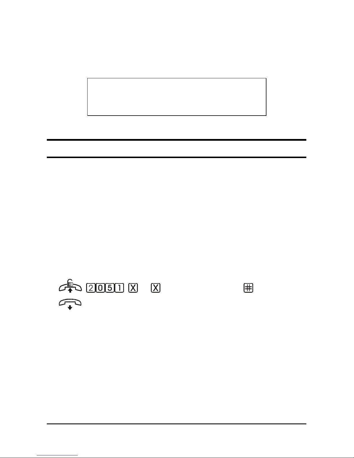
... (telephone number) (confirm)
Pick up the handset of the system administrator extension (401).
Dial the code 2051.
Dial the Remote Programming Number (max. 19 digits).
Dial # to confirm.
Wait for the confirmation tone and hang up.

Pagina 54 PROGRAMMINGS
Delete Remote Programming Number
(confirm)
Pick up the handset of the system administrator extension (401).
Dial the code 2050.
Wait for the confirmation tone and hang up.
D
EVICE RESET
Allows the Hi-Pro functional reset.
The reset does not modify the device programmings.
(confirm)
Pick up the handset of the system administrator extension (401).
Dial the code 2042580.
Wait for the confirmation tone and hang up.
R
ESTORING THE FACTORY SETTINGS
The restoration of the Hi-Pro factory settings is carried out by recalling one of
the seven basic default configurations: Default, Home, Home /Office, Office
with FAX line, Office with GSM line or Office with FAX and GSM line.
Recalling a default configuration brings each programming to the default
values of that configuration.
The numbers stored in the phonebook, and the call reports stored in the buffer
memory are not removed, while the voicemail is completely reset.
In order to recall a default configuration, follow the procedure described
at page. 41.
Note: restoring the factory settings does not delete the Hi-Pro system
messages.

PROGRAMMINGS Pagina 55
Deleting the phonebook and the buffer memory
Allows deleting all the numbers stored in the phonebook and all the calls
present in the buffer memory .
(confirm)
Pick up the handset of the system administrator extension (401).
Dial the code 204426580.
Wait for the confirmation tone and hang up.
C
LOCK
Note: the date/time setting is not password-protected.
Date
Allows you to update the date.
( day) ( month) ( year)
(confirm)
Pick up the handset of the system administrator extension (401).
Dial the code 2100.
Dial two digits for the day, two digits for the month and four digits for
the year.
Wait for the confirmation tone and hang up.
E.g.: supposing it’s the 10th of May, 2011, in order to program the
correct date, dial the following digits: 2100 10052011.
Time
Allows you to update the time.
(hour) (minutes) (confirm)
Pick up the handset of the system administrator extension (401).

Pagina 56 PROGRAMMINGS
Dial the code 2101.
Dial two digits for the hour and two digits for the minutes.
Wait for the confirmation tone and hang up.
E.g.: supposing it is 18:05, in order to program the correct time, dial the
following digits: 2101 1805.
Daylight saving time
Allows yuo to enabled the DST service.
DEFAULT: enabled.
(enable) (confirm)
Pick up the handset of the system administrator extension (401).
Dial the code 2109.
Dial:
0 to DISABLED the service
1 to ENABLED the service
Wait for the confirmation tone and hang up.

PROGRAMMINGS Pagina 57
P
ROFILES
The profile identifies the Hi-Pro behaviour according to the user’s needs:
DAY: the user is at home/in the office;
NIGHT: the user is not at home/in the office;
CUSTOM: the user is in a different situation.
These different profiles may be recalled either automatically according to the
set time band, or manually (see “Profiles” paragraph in User Manual).
DEFAULT:
- DAY profile for the Default and Home configurations;
- profile according to the time bands for all other configurations (DAY profile
from 8.00 a.m. to 12.00 p.m. and from 2.00 p.m. to 6.00 p.m., NIGHT profile
during the rest of the day and on Saturday and Sunday).
Daily time band
Allows setting up the beginning and the end of 2 time intervals, in which HiPro will use the NIGHT or the CUSTOM profiles. Outside these 2 intervals,
Hi-Pro will use the DAY profile.
Activating time band 1
(start: hour and minutes)
(end: hour and minutes) (profile) (confirm)
Pick up the handset of the system administrator extension (401).
Dial the code 2021.
Dial the starting hour (2 digits) and minutes (2 digits) of time band 1.
Dial the ending hour (2 digits) and minutes (2 digits) of time band 1.
Dial the digit referring to the profile to be used during this time band:
1 NIGHT profile
2 CUSTOM profile
Wait for the confirmation tone and hang up.
E.g.: if during the lunch break, from 12:00 to 14:00, you want to use the
CUSTOM profile, dial: 2021 1200 1400 2.
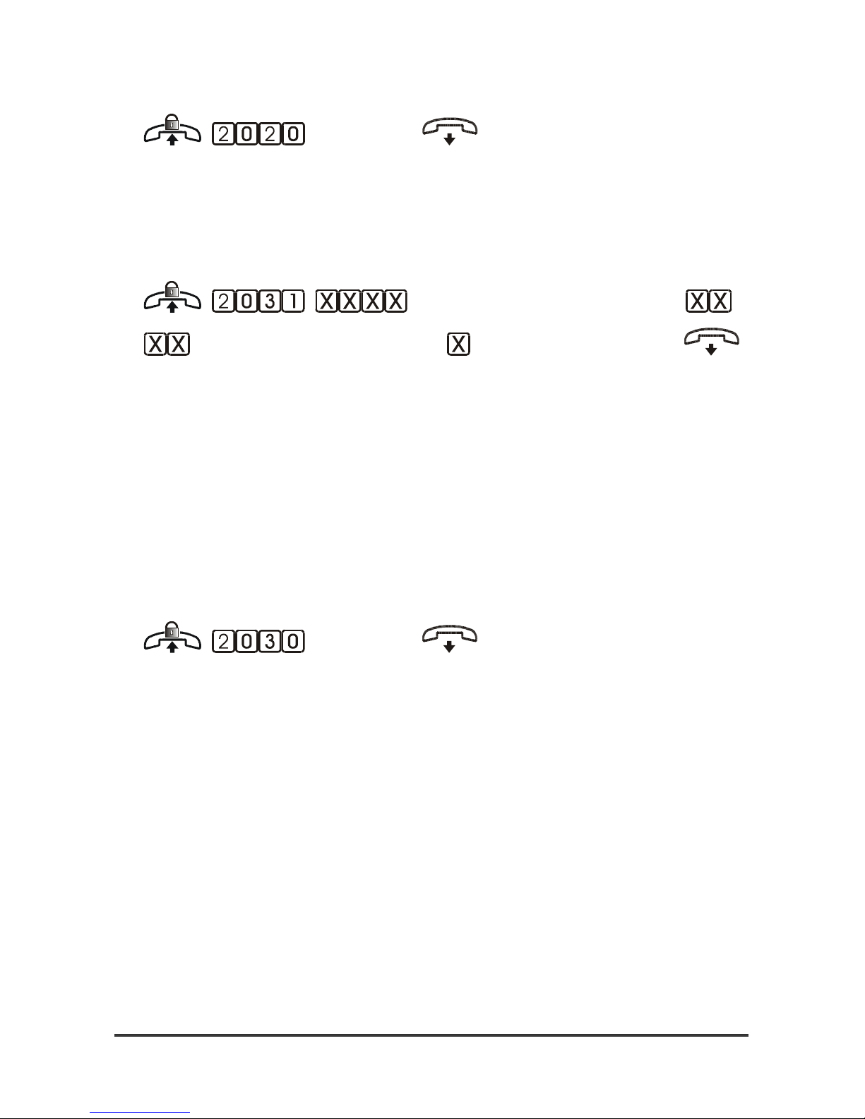
Pagina 58 PROGRAMMINGS
Deactivating time band 1
(confirm)
Pick up the handset of the system administrator extension (401).
Dial the code 2020.
Wait for the confirmation tone and hang up.
Activating time band 2
(start: hour and minutes)
(end: hour and minutes) (profile) (confirm)
Pick up the handset of the system administrator extension (401).
Dial the code 2031.
Dial the starting hour (2 digits) and minutes (2 digits) of time band 2.
Dial the ending hour (2 digits) and minutes (2 digits) of time band 2.
Dial the digit referring to the profile to be used during this time band:
1 NIGHT profile
2 CUSTOM profile
Wait for the confirmation tone and hang up.
Deactivating time band 2
(confirm)
Pick up the handset of the system administrator extension (401).
Dial the code 2030.
Wait for the confirmation tone and hang up.
Note: it is not mandatory to set both time bands.
Note: in the event the two time bands overlap, the last activated
time band has the priority.
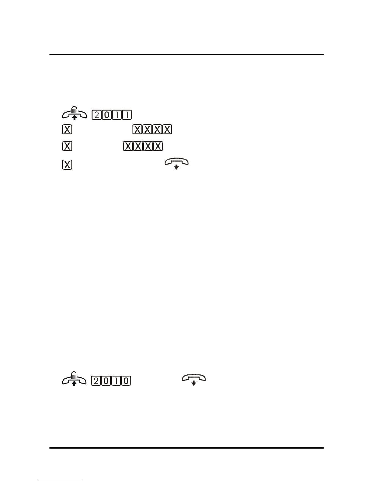
PROGRAMMINGS Pagina 59
Weekly time band
Allows you to set a period of the week during which Hi-Pro can automatically
activate a profile between NIGHT or CUSTOM.
DEFAULT: disabled.
Activating
(start: day) (start: hour and minutes)
(end: day) (end: hour and minutes)
(profile) (confirm)
Pick up the handset of the system administrator extension (401).
Dial the code 2011.
Dial the digit corresponding to the starting day of the weekly time band:
1 = Monday… 7 = Sunday.
Dial the starting hour (two digits) and minutes (two digits) of the weekly
time band.
Dial the digit corresponding to the ending day of the weekly time band:
1 = Monday… 7 = Sunday.
Dial the ending hour (two digits) and minutes (two digits) of the weekly
time band.
Dial the digit referring to the profile to be used during this time band:
1 NIGHT profile
2 CUSTOM profile
Wait for the confirmation tone and hang up.
E.g.: to set the weekly time band from 18:15 on Friday to 08:00 on
Monday with CUSTOM profile, dial: 2011 5 1815 1 0800 2.
Deactivating
(confirm)
Pick up the handset of the system administrator extension (401).
Dial the code 2010.
Wait for the confirmation tone and hang up.

Pagina 60 PROGRAMMINGS
N
UMBERING
Extension numbering
This function allows assigning a conventional number to an extension (flexible
numbering).
Conventional numbering varies between 40 and 499.
DEFAULT: numbering goes from 401 to 412 and corresponds to the position
of the terminals on the device.
(extension position)
(conventional) (confirm)
Pick up the handset of the system administrator extension (401).
Dial the code 214.
Dial two digits (between 01 and 12) indicating the extension connection.
Dial the code 4.
Dial the digit or the two digits corresponding to the extension numbering
to be assigned.
Dial # to confirm.
Wait for the confirmation tone and hang up.
Note: extension numbers must imperatively start with 4.
Note: the same number cannot be assigned to more than one
extension.
Note: if you set a two-digit number for an extension (e.g. 41), three-digit
numbers starting with the same digit (e.g. 410, 411, etc.) cannot be
used for other extensions.

PROGRAMMINGS Pagina 61
I
NTERNAL CALL GROUP
Hi-Pro allows the creation of two internal call groups.
The extensions belonging to a call group can be reached by the same internal
call at the same time. This way, it is possible to look for a person in different
rooms without having to call all the extensions one by one.
DEFAULT:
- group 1 (number 413): extensions 401~412;
- group 1 (number 414): extensions 401~406.
Call group numbering
Allows assigning a conventional number (flexible numbering) to a call group.
Conventional numbering may vary between 40 and 499.
DEFAULT:
- group 1: number 413;
- group 2: number 414.
(call group) (conventional)
(confirm)
Pick up the handset of the system administrator extension (401).
Dial the code 2130.
Dial a digit (between 1 and 2) indicating the call group.
Dial the code 4.
Dial the digit or the two digits corresponding to the extension number to
be assigned.
Dial # to confirm.
Wait for the confirmation tone and hang up.
Note: call group numbers must imperatively start with 4.
Note: the same number cannot be assigned to both call groups.
Furthermore, a number that has been assigned to an
extension cannot be assigned to a call group.
Note: if you set a two-digit number for an extension (e.g41), three-
digit numbers starting with the same digit (e.g 411, 412, etc.)
cannot be used for other extensions.
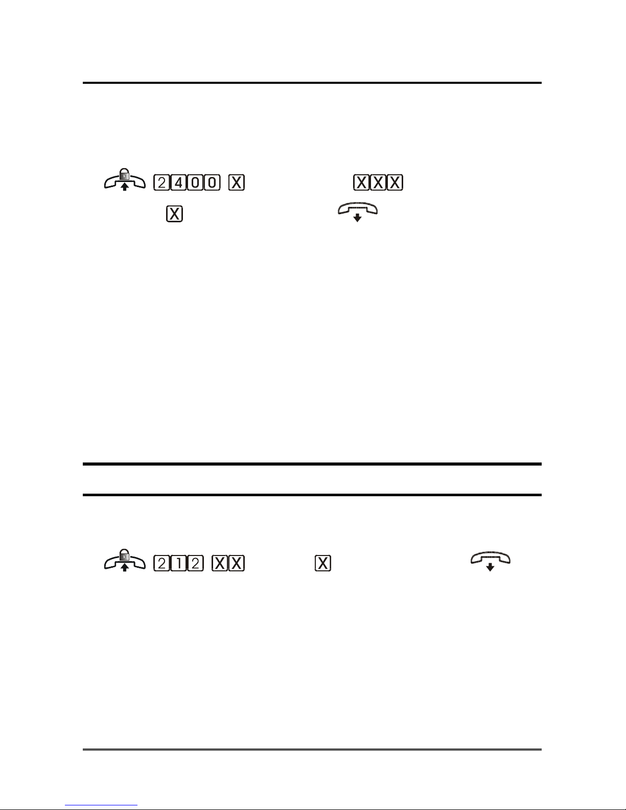
Pagina 62 PROGRAMMINGS
Creating call groups
Allows adding or removing an extension from a call group.
DEFAULT:
- group 1 (number 413): extensions 401~412;
- group 1 (number 414): extensions 401~406.
(call group) (extension
number) (action) (confirm)
Pick up the handset of the system administrator extension (401).
Dial the code 2400.
Dial:
1 for call group 1
2 for call group 2
Dial the two (or three) digits indicating the extension number.
Dial:
0 to REMOVE the extension
1 to ADD the extension
Wait for the confirmation tone and hang up.
T
RUNK LINES PROGRAMMING
Allows defining the presence of the various lines.
DEFAULT: all lines (depending on PBX equipment) are present.
(trunk) (type) (confirm)
Pick up the handset of the system administrator extension (401).
Dial the code 212.
Dial two digits (from 01 to 06) to indicate the number of the trunk line.
Dial:
0 Line excluded
2 Line with tone dialling
3 ISDN line
Wait for the confirmation tone and replace the handset.

PROGRAMMINGS Pagina 63
Note: this configuration is useful in case of unused trunk input.
ISDN
OPTIONS
BRI ISDN lines can be configured as:
• Point-to-Point
• Point-to-Multipoint
“Mono-number” contract:
The carrier delivers one socket with one telephone number and two voice
channels.
You need to:
• Configure the BRI as Point-to-Point or Point-to-Multipoint according to
the line type (please refer to the telephone carrier). Generally, the line is
Point-to-Multipoint in this case.
• Program both the BRI channels with the telephone number given by the
carrier (please see the “Errore. L'origine riferimento non è stata trovata.”
section).
“MSN” contract:
The carrier delivers one socket with max. 8 telephone numbers and two voice
channels.
You need to:
• Configure the BRI as Point-to-Point or Point-to-Multipoint according to
the line type (please refer to the telephone carrier). Generally, the line is
Point-to-Multipoint in this case.
• Programme the BRI lines with the telephone numbers given in the contract
(please see the “Errore. L'origine riferimento non è stata trovata.”
section).
Type of ISDN line
(BRI) (type) (confirm)
Pick up the handset of the system administrator extension (401).
Dial the code 2701.
Dial:

Pagina 64 PROGRAMMINGS
1 BRI T01
2 BRI T02
Dial:
0 Point-to-point
1 Point-to-multipoint
Wait for the confirmation tone and replace the handset.
TEI programming
You can assign a TEI value to each BRI. In the ISDN protocol the TEI value
can be set manually (values from 00 to 63) or automatically assigned by the
exchange to the terminal (values from 64 to 127).
(BRI) (TEI) (confirm)
Pick up the handset of the system administrator extension (401).
Dial the code 2706.
Dial:
1 BRI T01
2 BRI T02
Dial the TEI value (00-63 for manual and 64 for automatic mode).
Wait for the confirmation tone and replace the handset.
Note: the default TEI value is 00 for each BRI.
Note: for the automatic mode you must program the value 64.
BRI Numbers programming
Allows defining a table of the telephone numbers given by the carrier for each
BRI.
(BRI) (location 1~8) ...
(number) (confirm)
Pick up the handset of the system administrator extension (401).
Dial the code 2711.
Dial:
1 BRI T01
2 BRI T02
Dial the location in the table (from 1 to 8).
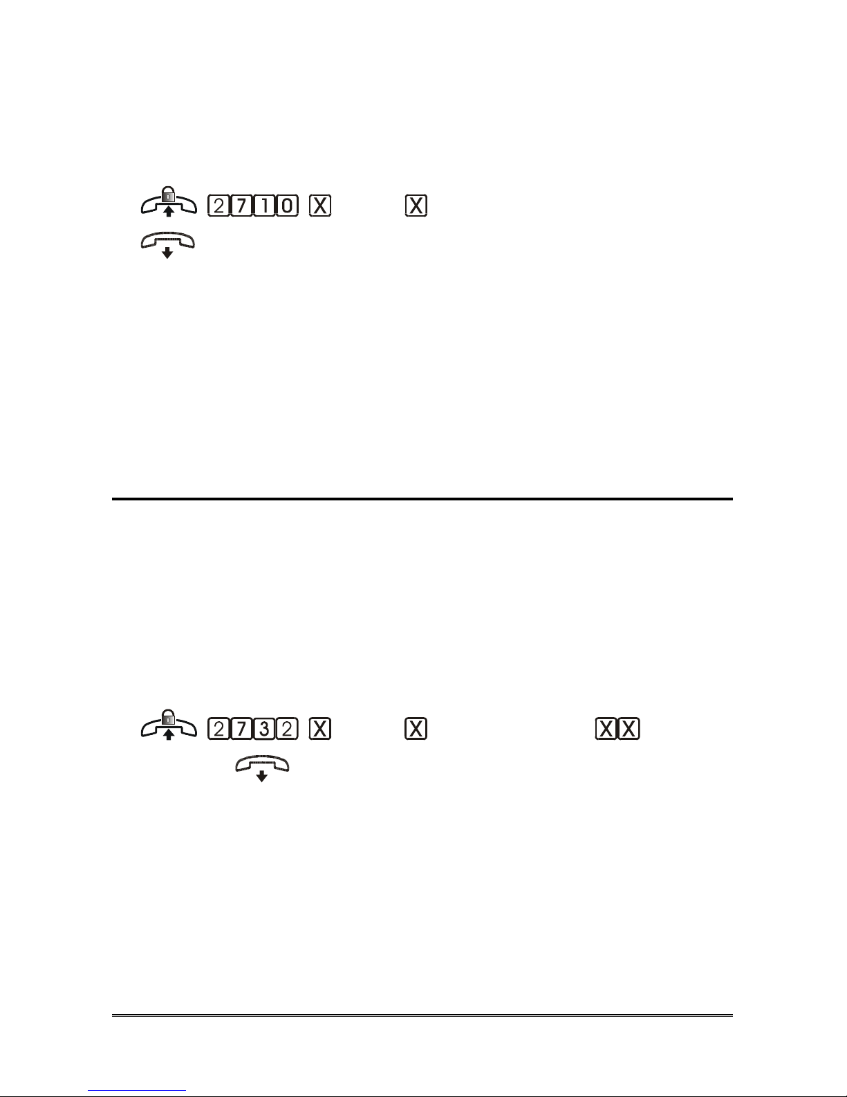
PROGRAMMINGS Pagina 65
Dial the telephone number given by the carrier (max 16 cifre).
Dial # to confirm.
Wait for the confirmation tone and replace the handset.
Deleting a number
(BRI) (location 1~8) (confirm)
Pick up the handset of the system administrator extension (401).
Dial the code 2710.
Dial:
1 BRI T01
2 BRI T02
Dial the location in the table (from 1 to 8).
Wait for the confirmation tone and replace the handset.
Incoming calls managing
For each number given by the carrier and inserted in the table of “BRI
numbers”, it is possible to diver incoming call :
- to a group of extensions (using VIP call)
- to one of the BRI trunk (L01 and L02 for T01, L03 and L04 for T02)
- to a single extension and then to a trunk or to a VIP call (virtual trunk)
(to define the working mode of a trunk or a virtual trunk, see “Incoming Calls”
chapter).
Associate a BRI number to a trunk or to a virtual trunk (VIP)
(BRI) (location 1~8) (trunk)
(confirm)
Pick up the handset of the system administrator extension (401).
Dial the code 2732.
Dial:
1 BRI T01
2 BRI T02
Dial the location in the table (from 1 to 8).
Dial the trunk number:
01 Trunk L01 (only for T01)

Pagina 66 PROGRAMMINGS
02 Trunk L02 (only for T01)
03 Trunk L03 (only for T02)
04 Trunk L04 (only for T02)
11 Trunk VIP1
12 Trunk VIP2
13 Trunk VIP3
14 Trunk VIP4
15 Trunk VIP5
16 Trunk VIP6
17 Trunk VIP7
18 Trunk VIP8
Wait for the confirmation tone and replace the handset.
Associate a BRI number to a single extension
(BRI) (location 1~8)
(extension) (confirm)
Pick up the handset of the system administrator extension (401).
Dial the code 2731.
Dial:
1 BRI T01
2 BRI T02
Dial the location in the table (from 1 to 8).
Dial the two (or three) digits of the extension where the call is to be
presented.
Wait for the confirmation tone and replace the handset.
Note: in event of the extension specified:
- does not answer
- has enabled “Do Not Disturb from DISA or DDI”
- is not enabled to receive DISA or DDI call
and the “General call for unanswered DISA" function is
enabled for the extension (see paragraph “Enabling
Services”), the call is sent to the trunk or virtual trunk (VIP)
associated to the BRI number.
If the “General call for unanswered DISA" function is not
enabled for the extension , the call is cleared.
Finally, if the extension is busy, the caller receive a busy tone.

PROGRAMMINGS Pagina 67
Delete an association
(BRI) (location 1~8) (confirm)
Pick up the handset of the system administrator extension (401).
Dial the code 2730.
Dial:
1 BRI T01
2 BRI T02
Dial the location in the table (from 1 to 8; or 9: all locations).
Wait for the confirmation tone and replace the handset.
IDs Managing
Outgoing calls IDs
Allows to define which of the BRI numbers in the table will be used by each
extension as its identifier in outgoing calls.
DEFAULT: all extensions use the first number in table of each BRI.
(BRI) (extension)
(location 1~8) (confirm)
Pick up the handset of the system administrator extension (401).
Dial the code 2737.
Dial:
1 BRI T01
2 BRI T02
Dial the two (or three) digits of the extension.
Dial the location in the table (from 1 to 8) of the number chosen as
outgoing ID.
Wait for the confirmation tone and replace the handset.
ID Sending Mode (CLIR)
This configuration allows to set if send or not the caller ID to the remote user.
(BRI) (mode) (confirm)
Pick up the handset of the system administrator extension (401).
Dial the code 2702.

Pagina 68 PROGRAMMINGS
Dial:
1 BRI T01
2 BRI T02
Dial:
0 Caller ID is sent
1 Caller ID is not sent
Wait for the confirmation tone and replace the handset.
Note: the modification of the ID mode must be supported by the
public telephone network.
ID Sending Mode, if connected user (COLR)
This configuration allows to set if send or not the ID to the remote caller.
(BRI) (mode) (confirm)
Pick up the handset of the system administrator extension (401).
Dial the code 2703.
Dial:
1 BRI T01
2 BRI T02
Dial:
0 Caller ID is sent
1 Caller ID is not sent
Wait for the confirmation tone and replace the handset.
Note: the modification of the ID mode must be supported by the
public telephone network.

PROGRAMMINGS Pagina 69
E
XTENSION PROGRAMMING
Outgoing calls
Allows to define the lines each extension is enabled to use for outgoing calls,
under each profile.
DEFAULT: under any profile, all extension are enabled to use all lines
available.
(extension) (profile)
(trunk) (enable) (confirm)
Pick up the handset of the system administrator extension (401).
Dial the code 22.
Dial the two (or three) digits of the extension number.
Dial:
0 DAY profile
1 NIGHT profile
2 CUSTOM profile
3 All profiles
Dial the code 14.
Dial two digits (from 01 to 04) to indicate the number of the trunk line.
Dial:
0 Disabled
1 Enabled
Wait for the confirmation tone and replace the handset.
Lines engagement order
It allows, for each extension, to indicate the priority order of external
lines, when dialling 0 key. The order of engagement is defined by the Lines
Engagement Table (see the next paragraph).
DEFAULT: mode 01.
(extension) (trunk
engagement mode)
(confirm)

Pagina 70 PROGRAMMINGS
Pick up the handset of the system administrator extension (401).
Dial the code 2179.
Dial the two (or three) digits of the extension number.
Dial two digits to indicate the selected mode in the Lines Engagement
Table (01~08).
Dial # to confirm.
Wait for the confirmation tone and replace the handset.
Lines Engagement Table programming
The Lines Engagement Table allows to define until 8 different line engagement
modes. For each one it is also possible to set if the engagement mode is cyclical
or not.
DEFAULT:
Mode Cyclical 1° line 2° line 3° line 4° line
01 no L01 L02 L03 L04
02 no L01 L02 L03
03 no L01 L02
04 no L03 L04
05 no L01
06 no L02
07 no L03
08 no L04 L03 L02 L01
(table position) (cyclical
engage) (trunks) (confirm)
Pick up the handset of the system administrator extension (401).
Dial the code 211.
Dial two digits to indicate the selected mode in the Lines Engagement
Table (01~08).
Dial:
0 Cyclical line engagement disabled
1 Cyclical line engagement enabled
Dial the line numbers (01~04) in the desired order.
Dial # to confirm.

PROGRAMMINGS Pagina 71
Wait for the confirmation tone and replace the handset.
Note: enter all lines is not needed. Not inserted lines won't be never
engaged by dialling 0 key.
Doorphone calls
This function allows you to enable extensions to receive calls from doorphone
stations and to open the doors. For each extension and doorphone station it is
possible to set:
No access the extension is not enabled to answer doorphone calls
and the door opener is disabled;
Call pick-up the extension does not ring, doorphone calls can be
answered with code 5; the door opener is enabled;
Ring the extension rings, incoming calls can be answered by
lifting the handset; the door opener is enabled;
Timed Ring the extension rings after 20 seconds (customizable
timer). Before it stars ringing doorphone calls can be
answered with code 5; while when it starts ringing
incoming calls can be answered by lifting the handset;
the door opener is enabled.
DEFAULT:
- Default and Home configurations: all extension will ring in event of
doorphone call;
- Home/Office configuration: under any profile, home extensions (401~404)
will ring in event of call from Doorphone 1; during NIGHT and CUSTOM
profiles, office extensions (405~412) will ring in event of call from Doorphone
2; while during DAY profile, only first office extension (405) will ring in event
of call from Doorphone 2; other office extensions will ring with a time-delay;
- Office and Office with dedicated GSM line configurations: during NIGHT
and CUSTOM profiles, all extensions will ring in event of Doorphone call,
while, during DAY profile, only first extension (401) will ring; other extensions
will ring with a time-delay;
- Office with dedicated FAX line and Office with dedicated GSM and FAX
line configurations: during NIGHT and CUSTOM profiles, all extensions
(except for FAX) will ring in event of Doorphone call, while, during DAY
profile, only first extension (401) will ring; other extensions (except for FAX)
will ring with a time-delay.

Pagina 72 PROGRAMMINGS
(extension) (profile)
(doorphone) (mode) (confirm)
Pick up the handset of the system administrator extension (401).
Dial the code 22.
Dial the two (or three) digits of the extension number.
Dial:
0 DAY profile
1 NIGHT profile
2 CUSTOM profile
3 All profiles
Dial the code 01.
Dial:
1 Doorphone 1
2 Doorphone 2
Dial:
0 No access
1 Call pick-up and door opening
2 Ring and door opening
3 Timed ring and door opening
Wait for the confirmation tone and replace the handset.
Unrestricted numbers
This function allows you to define the numbers that can be dialled for each
extension. It also allows to associate service classes to the extensions (see
“Service classes”).
DEFAULT: each extension is associated with all filter groups, except for class
8, which includes the telephone codes of premium service numbers.
( unrestricted) (extension)
(profile) (class) (confirm)
Pick up the handset of the system administrator extension (401).
Dial the code 2170.
Dial:
0 Class not associated with extension
1 Class associated with extension

PROGRAMMINGS Pagina 73
Dial the two (or three) digits indicating the extension number.
Dial:
0 DAY profile
1 NIGHT profile
2 CUSTOM profile
3 All profiles
Dial the two digits (between 01 and 08) indicating the service class.
Wait for the confirmation tone and replace the handset.
Note: an extension that is not associated to any group will not be
able to make any calls over the external line.
Note: if you assign the extension to only one service class, (i.e. the
class that permits calls starting with 0) you hear the
dissuasion tone when dialling area codes starting with 0 that
are inserted in other classes.
Example: if the extension is associated with the filter group that allows
calls starting with 0, but is not associated with the 07 filter group, you
will hear the dissuasion tone if you dial 07.
Service activation
Allows activating the following services for each extension:
Unlimited phonebook
recall
Allows the extension to bypass dialling filters to
call the numbers stored in the phonebook.
Timed call forwarding
Allows the extension to activate the timed call
forwarding service.
Call forwarding on
busy user
Allows the extension to activate the call
forwarding service on busy user.
Call forwarding all
calls
Allows the extension to divert all calls to another
extension.
Automatic engagement
Allows the extension to access external lines
without dialling 0.
Selective call pick up
Allows the other extensions to intercept calls
(external and internal) towards the extension in
question.

Pagina 74 PROGRAMMINGS
DISA or “DDI from
phonebook” calls (VIP)
Allows the extension to receive DISA or “DDI
from phonebook” calls (VIP calls).
Voicemail
Allows the extension to access voicemail service.
Amplifier
Allows the extension to make announcements via
the amplifier connected to Hi-Pro.
External call
forwarding
Allows the extension to activate the automatic
external call forwarding service.
Relay activation
Allows the extension to activate the relays.
Do not disturb
Allows the extension to activate the “do not
disturb” services.
Doorphone call
forwarding
Allows the extension to activate the doorphone call
forwarding service.
Trunk to Trunk
Conversation
Allows the extension to access to the Trunk to
Trunk Conversation service.
ETSI External call
forwarding
Allows the extension to acce
ss to the activation of
ETSI call forwarding service.
Alarm button (only
with ST 350
telephones)
Allows the extension to generate an alarm by
pressing the special button on the ST 350
telephone.
No dial alarm
Allows the extension to generate an alarm in case
of no dialling.
L.C.R.
Allows the extension to activate control on the
outgoing calls based on Least Cost Routing
settings.
General call in case of
unanswered DISA or
VIP call
This option determines whether a DISA or VIP
call, unanswered by the extension after a set time,
should be converted into a general call.
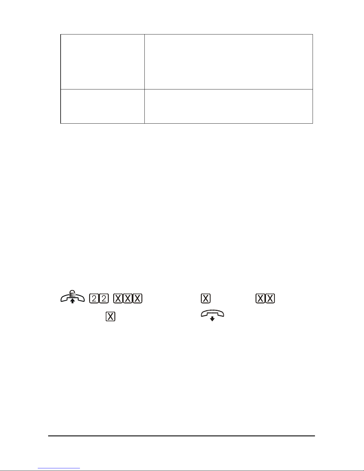
PROGRAMMINGS Pagina 75
Basic call pick up (only
with ST 600
telephones)
Allows the extension to answer one or more
incoming external calls during conversation, or
when not enabled to ring, by pressing the
(L01~L04) button on the ST 600 telephones. The
conversation in progress is put on hold.
Selective pick up (only
with ST 600
telephones)
Allows answering one or more incoming external
calls by simply pressing the (L01~L04) button on
the ST 600 telephones.
DEFAULT:
- the following services: time call forwarding, call forwarding on busy user, call
forwarding all calls, do not disturb, Trunk to Trunk Conversation, ETSI
external call forwarding, no dial alarm, basic call pick up and selective pick up,
are not enabled for any extension;
- the following services: external call forwarding, doorphone call forwarding,
relay activation, amplifier, voicemail, DISA or VIP call, general call in case of
unanswered DISA or VIP call, selective pick up, unlimited phonebook recall,
ST 350 alarm button, are enabled for every extension;
- the “automatic engagement” service is enabled for every extension in Home
configuration, while it is enabled only for extension 408 (FAX extension) in
Home / Office, Office, Office with dedicated FAX line and Office with
dedicated GSM and FAX line configurations.
- the L.C.R. service is active in Office with dedicated GSM line and Office
with dedicated GSM and FAX line GSM configurations.
(extension) (profile)
(service) (enable) (confirm)
Pick up the handset of the system administrator extension (401).
Dial the code 22.
Dial the two (or three) digits indicating the extension number.
Dial:
0 DAY profile
1 NIGHT profile
2 CUSTOM profile
3 All Profiles

Pagina 76 PROGRAMMINGS
Dial:
13 Unlimited phonebook recall
30 Access to Timed call forwarding service
31 Access to Call forwarding on busy user service
32 Access to Call forwarding all calls service
33 Automatic engagement
34 Selective call pick up
35 DISA or “DDI from phonebook” calls (VIP calls)
36 Access to Voicemail service
37 Amplifier
38 External call forwarding
39 Relay activation
40 Access to Do not disturb service
41 Doorphone call forwarding
42 Access to Trunk to Trunk Conversation service
43 Access to ETSI external call forwarding service
50 ST 350 Alarm button
51 No dial alarm
80 L.C.R.
82 General call in case of unanswered DISA or VIP call
84 Basic call pick up
85 Selective pick up
Dial:
0 to DISABLE the service
1 to ENABLE the service
Wait for the confirmation tone and hang up.
I
NCOMING CALLS
The fully equipped Hi-Pro is provided with four analogue and/or ISDN lines
for incoming calls.
Furthermore, Hi-Pro is provided with an automatic call distribution system
(ACD) based on caller ID.
Thanks to the ACD system, it is possible to address incoming calls from a
certain telephone number to a single extension, or to a group of extensions, or
again, to a single extension first, and then to a group of extensions.
The routing of the calls to groups of extensions is carried out via virtual lines
named VIP1 ...VIP8. Just as for the real line, also for the VIP line it is possible
to determine the behaviour of the various extensions and the active services. As

PROGRAMMINGS Pagina 77
for the telephone numbers associated with a VIP line, please consult the chapter
“ACD”.
Programming incoming calls
This programming allows defining the behaviour of the extensions after an
incoming call over each real or virtual line. For every extension and for every
line it is possible to determine:
Call excluded the extension is not enabled to answer incoming calls
over a certain line;
Call pick up the telephone does not ring, but incoming calls can be
answered with code 5;
Ring the telephone rings, to answer the incoming call it is
sufficient to pick up the handset.
Timed ring the phone starts to ring only after 20 seconds. Before
the incoming calls can be answered with code 5; while
when it starts ringing incoming calls can be answered
by lifting the handset.
DEFAULT:
- Default configuration: all the extensions will ring regardless of the profile and
the line;
- Home configuration: during DAY and NIGHT profiles all the extensions will
ring regardless of the line, during CUSTOM profile, the incoming calls over the
real lines will make only extension 401 ring, while the incoming calls over the
VIP will make all the extensions ring;
- Home / Office configuration: the incoming calls over L01 will make home
extensions (401~404) ring regardless of the profile; during NIGHT and
CUSTOM profile, the incoming calls over L02~L04 will make office
extensions (405~412), while, during DAY profile, only first office extension
(405) will ring, all other office extensions will ring with a time-delay;
- Office and Office with dedicated GSM line configurations: during NIGHT
and CUSTOM profile all the extensions will ring regardless of the line, while,
during DAY profile, only first extension (401) will ring, all other office
extensions will ring with a time-delay;
- Office with dedicated FAX line and Office with dedicated GSM and FAX
line configurations: the incoming calls over FAX line (L02 o L04) will make
only FAX extension (408) regardless of the profile; during NIGHT and
CUSTOM profile, the incoming calls over the other lines will make all the
extensions (except for FAX 408) ring, while, during DAY profile, only first

Pagina 78 PROGRAMMINGS
extension (401) will ring, all other extensions (except for FAX 408) will ring
with a time-delay.
(extension) (profile)
(line) (enable) (confirm)
Pick up the handset of the system administrator extension (401).
Dial the code 22.
Dial the two (or three) digits indicating the extension number.
Dial:
0 DAY profile
1 NIGHT profile
2 CUSTOM profile
3 All profiles
Dial 00.
Dial line number:
01 Line L01
02 Line L02
03 Line L03
04 Line L04
11 VIP1 Line
12 VIP2 Line
13 VIP3 Line
14 VIP4 Line
15 VIP5 Line
16 VIP6 Line
17 VIP7 Line
18 VIP8 Line
Dial activation number:
0 Call excluded
1 Call pick up
2 Ring
3 Timed ring
Wait for the confirmation tone and hang up.
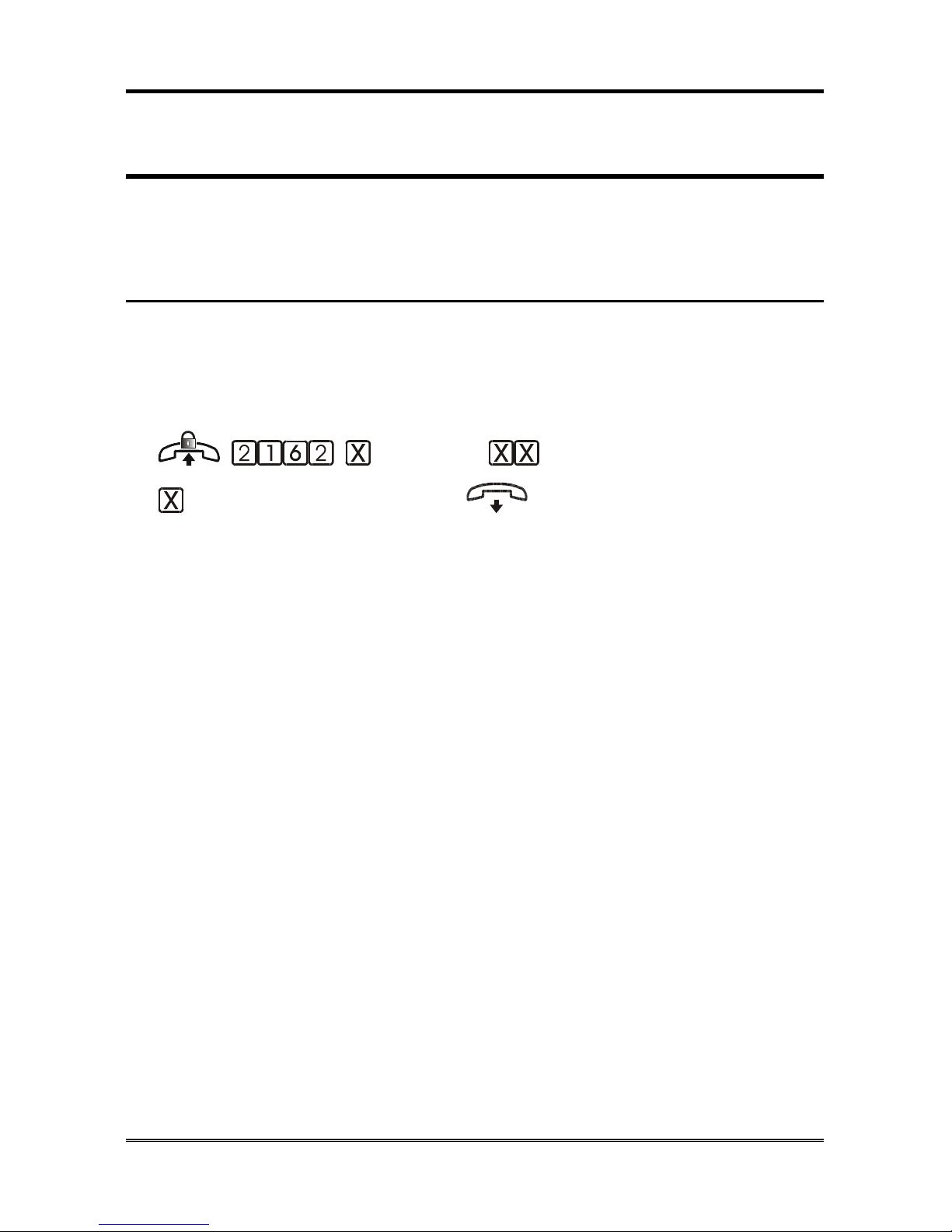
PROGRAMMINGS Pagina 79
L
INE ACTIVATION FOR EXTERNAL CALL
FORWARDING
It allows determining, for each external line, whether the incoming calls over
that line can be diverted via the external call forwarding service.
Analogue Lines
DEFAULT:
- Default configuration: call forwarding enabled regardless of the profile and
the line;
- all other configurations: call forwarding enabled only during NIGHT profile.
(profile) (line)
( activation) (confirm)
Pick up the handset of the system administrator extension (401).
Dial the code 2162.
Dial:
0 DAY profile
1 NIGHT profile
2 CUSTOM profile
3 All profiles
Dial line number (01~04).
Dial:
0 to DISABLE the service
1 to ENABLE the service
Wait for the confirmation tone and hang up.
Note: for the actual activation of the external call forwarding
service, please refer to paragraph “External call forwarding”
of the User Manual.

Pagina 80 PROGRAMMINGS
ISDN Lines
DEFAULT:
- Default configuration: call forwarding enabled for all numbers inserted in the
table of “BRI numbers”, regardless of the profile;
- all other configurations: call forwarding enabled only during NIGHT profile
regardless of the BRI number.
(BRI) (location 1~8) (profile)
(activation) (confirm)
Pick up the handset of the system administrator extension (401).
Dial the code 2733.
Dial:
1 BRI T01
2 BRI T02
Dial the location in the table (from 1 to 8).
Dial:
0 DAY profile
1 NIGHT profile
2 CUSTOM profile
3 All profiles
Dial:
0 to DISABLE the service
1 to ENABLE the service
Wait for the confirmation tone and hang up.
Note: for the actual activation of the external call forwarding
service, please refer to paragraph “External call forwarding”
of the User Manual.

PROGRAMMINGS Pagina 81
E
NABLING DOORPHONE CALL FORWARDING
Allows determining (indicating the priority order of engagement) to which
external line the doorphone calls can be diverted, through the doorphone call
forwarding service.
DEFAULT:
- Default configuration: doorphone call forwarding enabled regardless of the
profile and the line (with line engagement mode 01);
- other configurations: doorphone call forwarding enabled only during NIGHT
profile (with line engagement mode 01).
(profile) (doorphone station)
(line engagement mode) (confirm)
Pick up the handset of the system administrator extension (401).
Dial the code 2180.
Dial:
1 DAY profile
1 NIGHT profile
2 CUSTOM profile
3 All profiles
Dial:
1 Doorphone 1
2 Doorphone 2
Dial two digits to indicate the selected mode in the Lines Engagement
Table (01~08; 00: no line).
Wait for the confirmation tone and hang up.
Note: for the actual activation of the Doorphone call forwarding
service, please refer to paragraph “Doorphone call
forwarding” of the User Manual.

Pagina 82 PROGRAMMINGS
FAX
There are two different possibilities for FAX management:
- activate the FAX-switch service, which recognizes FAX call and redirects
them to the FAX extension;
- reserve a specific external line for FAXes, without activating FAX-switch
service.
In Home/Office and Office configurations the FAX-switch service is active,
while in Office with dedicated FAX line and Office with dedicated FAX and
GSM line one line is reserved for FAX receiving.
The following paragraph describes the programmings needed for both the
possibilities of FAX management.
Analogue line devoted to receiving all kinds of calls, using FAX recognition
- Define FAX extension (see “Dedicated FAX line
- Set the FAX extension with incoming calls with ringer (mode 2) (see
“Programm”).
- Disable calls from dedicated FAX line for all other extension.
- extension”).
- Enable FAX recognition (see “Note: to avoid the selection of “0”
(line engagement digit) from FAX extension, see “Automatic
Engagement” service in paragraph “Enable Services”
- recognition”).
- Disable FAX extension to ring upon incoming calls over the various lines
(see “Programming incoming calls”, enter the call pick up option).
Note: in the event a doorphone board is provided, predispose the
FAX extension with doorphone ringer disabled (see
“Doorphone calls”, enter access type 0 or 1).
Note: to avoid the selection of “0” (line engagement digit) from
FAX extension, see “Automatic Engagement” service in
paragraph “Enable Services”.
Dedicated FAX line
- Set the FAX extension with incoming calls with ringer (mode 2) (see
“Programm”).
- Disable calls from dedicated FAX line for all other extension.

PROGRAMMINGS Pagina 83
Programming the fax extension
Analogue lines
It allows you to set, for each external line, the extension where the calls
recognized by the FAX-switch are presented.
DEFAULT: 408 for all trunks.
(trunk) (extension) (confirm)

Pagina 84 PROGRAMMINGS
Pick up the handset of the system administrator extension (401).
Dial the code 239.
Dial line number (01~04).
Dial the two (or three) digits indicating the extension number to be
programmed as FAX.
Wait for the confirmation tone and hang up.
Note: to avoid the selection of “0” (line engagement digit) from
FAX extension, see “Automatic Engagement” service in
paragraph “Enable Services”.
ISDN Lines
It allows you to set, for each BRI, the extension where the calls recognized by
the FAX-switch are presented.
DEFAULT: 408 for both BRIs.
(BRI) (extension) (confirm)
Pick up the handset of the system administrator extension (401).
Dial the code 2707.
Dial:
1 BRI T01
2 BRI T02
Dial the two (or three) digits indicating the extension number to be
programmed as FAX.
Wait for the confirmation tone and hang up.
Note: to avoid the selection of “0” (line engagement digit) from
FAX extension, see “Automatic Engagement” service in
paragraph “Enable Services”
FAX-switch activation
Allows enabling automatic fax recognition over each external line.
Analogue lines
DEFAULT:
- Home/Office configuration: recognition enabled over L02~L04;
- Office configuration: recognition enabled over all the lines;
- all other configurations: recognition enabled over all lines.

PROGRAMMINGS Pagina 85
(trunk) (enable) (confirm)
Pick up the handset of the system administrator extension (401).
Dial the code 2163.
Dial line number (01~04).
Dial:
0 to DISABLE service
1 to ENABLE service
Wait for the confirmation tone and hang up.
Note: the activation of this service does not inhibit the display of the
caller identification (CLI) for the incoming calls over the line.
ISDN Lines
(BRI) (location 1~8) ( enable)
(confirm)
Pick up the handset of the system administrator extension (401).
Dial the code 2736.
Dial:
1 BRI T01
2 BRI T02
Dial the location in the table (from 1 to 8).
Dial:
0 to DISABLE service
1 to ENABLE service
Wait for the confirmation tone and hang up.
Note: the activation of this service does not inhibit the display of the
caller identification (CLI) for the incoming calls over the line.

Pagina 86 PROGRAMMINGS
M
ESSAGES
Hi-Pro is provided with 30 customisable messages, which are available for the
DISA, the Response, the Automatic operator and the Voicemail services.
As a default setting, messages 1~20 are enabled for use.
The first 13 messages are pre-recorded with a standard text.
DEFAULT:
Msg Protection Name Duration Quality
01 Protected Service disabled 5 6,4 kHz
02 Protected Service enabled 5 6,4 kHz
03 Protected Service carried out 5 6,4 kHz
04 Protected Not available 5 6,4 kHz
05 Non-Protected Controller 30 6,4 kHz
06 Protected Control menu 30 6,4 kHz
07 Protected Alarm Clock 10 6,4 kHz
08 Non-Protected Voicemail 1 20 6,4 kHz
09 Non-Protected Voicemail 2 20 6,4 kHz
10 Non-Protected Voicemail 3 20 6,4 kHz
11 Non-Protected DISA 30 6,4 kHz
12 Non-Protected Day responder 30 6,4 kHz
13 Non-Protected Night responder 30 6,4 kHz
Note: the quality and the duration of the messages can be modified
only via remote programmer software.
Note: Hi-pro 280 is provided with 30 recordable minutes (available
for the 30 customizable messages and Voicemail messages),
while 60 minute are available for 412 equippements.
Note: only messages with duration other than 0 will be enabled for
use.
Message recording/playback/deleting
Allows customising, playing back and deleting messages. The quality and the
duration of the messages can be modified only via remote programmer
software.
(message) (action) |
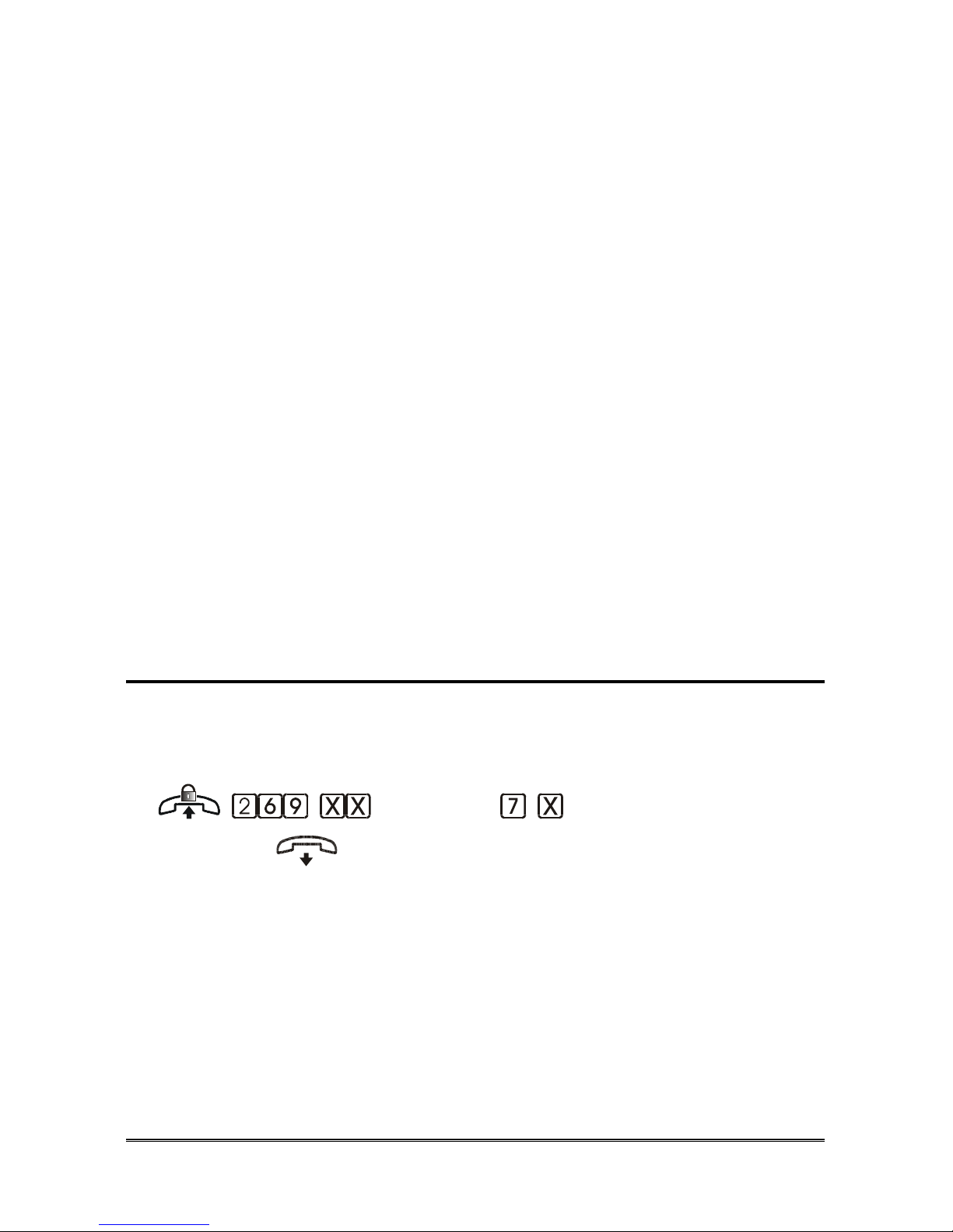
PROGRAMMINGS Pagina 87
Pick up the handset of the system administrator extension (401).
Dial the code 269.
Dial the message index from 01 to 30.
Dial:
0 to record
1 to play back
5 to delete
Press the R (flash) button, or hang up to end the procedure.
Note: recording can be performed only for non-protected messages
with a set duration other than 0.
Note: once exceeded the maximum recording time, you will hear a
confirmation tone.
Note: to end the recording procedure before the end of the set time,
press R or hang up.
Note: 01~13 factory pre-recorded messages can be overwrited, if
needed. In any case, they can be restored by deleting the
customized ones.
Note: message sequences can only be played back using as
message index 91 or 92. In order to customise them, it is
necessary to record the single messages.
Activate musical background
Allows to use the external music source (A50 or other) as messages musical
background.
DEFAULT: musical background activated for messages: 07, 11, 12 and 13.
(message) (activation)
(confirm)
Pick up the handset of the system administrator extension (401).
Dial the code 269.
Dial the message index (01~30).
Dial the code 7.
Dial:
0 to DISABLE the musical background
1 to ENABLE the musical background
Wait for the confirmation tone and hang up.

Pagina 88 PROGRAMMINGS
Note: for the activation of the External Music Source, please refer to
chapter “Errore. L'origine riferimento non è stata trovata.”.
Message protection
Allows activating/deactivating protection on message recording. A protected
message cannot be recorded.
DEFAULT: messages from 01 to 07 are protected, except for message 05.
(message) (activation)
(confirm)
Pick up the handset of the system administrator extension (401).
Dial the code 269.
Dial the message index (01~30).
Dial the code 8.
Dial:
0 to DISABLE protection
1 to ENABLE protection
Wait for the confirmation tone and hang up.
Note: protection activation can be made only for messages with
duration other than 0.
Creating message sequences
2 message sequences can be created by linking together two or three
customisable messages.
These “compound” messages will be number 91 and 92 respectively.
(sequence index) (1st
message) (2nd message) (3rd message)
(confirm)
Pick up the handset of the system administrator extension (401).
Dial the code 2761.
Dial the sequence index to be created (31 or 32).
Dial the index of the 1st message from 01 to 30.
Dial the index of the 2nd message from 01 to 30.

PROGRAMMINGS Pagina 89
Dial the index of the 3rd message from 01 to 30.
Wait for the confirmation tone and hang up.
Note: in the event you want to link together only two messages, the
code for the last message will be 00.
Note: only messages with duration other than 0 are enabled for use
and therefore, can be linked.
Deleting message sequences
Allows deleting message sequences defined in the previous paragraph.
(sequence index) (confirm)
Pick up the handset of the system administrator extension (401).
Dial the code 2760.
Dial the index of the sequence to be deleted (91 o 92).
Wait for the confirmation tone and hang up.
Activate musical background for message
sequences
Allows to use the external music source (A50 or other) as “compound”
messages musical background.
DEFAULT: musical background disabled.
(sequence index) (activation)
(confirm)
Pick up the handset of the system administrator extension (401).
Dial the code 2763.
Dial the index of the sequence (91 o 92).
Dial:
0 to DISABLE the musical background
1 to ENABLE the musical background
Wait for the confirmation tone and hang up.
Note: for the activation of the External Music Source, please refer to
chapter “Errore. L'origine riferimento non è stata trovata.”.
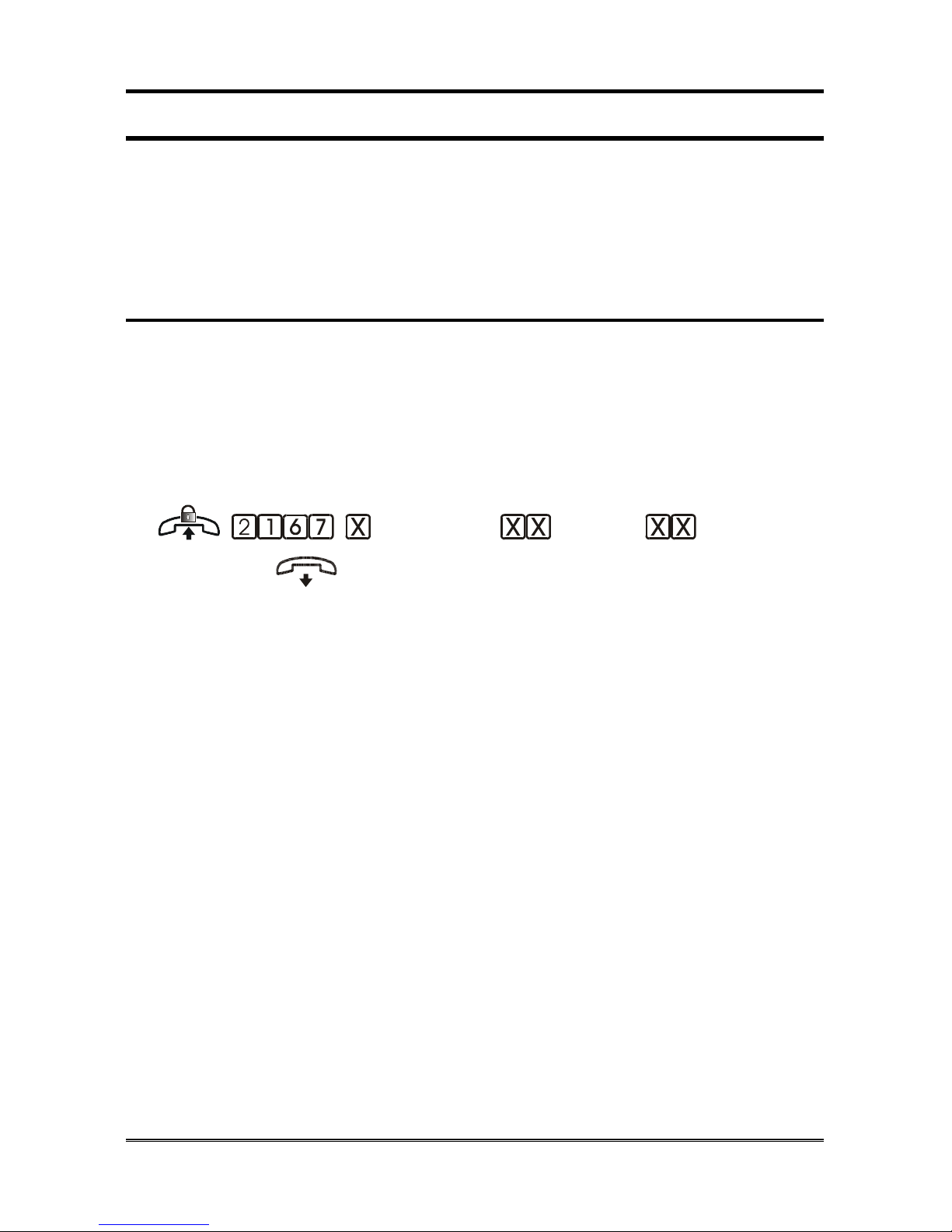
Pagina 90 PROGRAMMINGS
R
ESPONSE SERVICE
This service automatically responds to incoming calls, which the operator
cannot answer to in that moment, by sending a courtesy message according to
the profile used.
Note: the messages of the response service are customisable.
Choosing the Response message
This procedure assigns the message reproduced by the Response service,
according to the profile and the line.
DEFAULT:
- DAY profile: message 12, “We are busy at the moment, please hold the line”;
- NIGHT and CUSTOM profiles: message 13, “We are absent; please kindly
phone back”.
(profile) (line) (message)
(confirm)
Pick up the handset of the system administrator extension (401).
Dial the code 2167.
Dial:
0 DAY profile
1 NIGHT profile
2 CUSTOM profile
3 All profiles
Dial the line number:
01 Analogue line L01
02 Analogue line L02
03 Analogue line L03
04 Analogue line L04
11 VIP1 line
12 VIP2 line
13 VIP3 line
14 VIP4 line
15 VIP5 line
16 VIP6 line
17 VIP7 line
18 VIP8 line
99 All lines

PROGRAMMINGS Pagina 91
Dial the message index between 11 and 30 or 91 and 92.
Wait for the confirmation tone and hang up.
Note: only messages enabled for use, or compound messages can be
chosen.
Response programming
Allows activating the automatic response service over each line.
DEFAULT:
- Default and Home configurations: not enabled;
- Home /Office configurations: enabled over office lines (L02~L04) regardless
of the profile;
- all other configuration: on the real lines for all profiles.
(profile) (line)
(activation) (confirm)
Pick up the handset of the system administrator extension (401).
Dial the code 2161.
Dial:
0 DAY profile
1 NIGHT profile
2 CUSTOM profile
3 All profiles
Dial the line number:
01 Analogue line L01
02 Analogue line L02
03 Analogue line L03
04 Analogue line L04
11 VIP1 line
12 VIP2 line
13 VIP3 line
14 VIP4 line
15 VIP5 line
16 VIP6 line
17 VIP7 line
18 VIP8 line
Dial:
0 to DISABLE the service
1 to ENABLE the service

Pagina 92 PROGRAMMINGS
Wait for the confirmation tone and hang up.
DISA
SERVICE
The DISA (Direct Inward System Access) service allows an external caller to
call an extension directly (if the service is enabled for the extension). This
service sends a message to the external caller prompting to dial. The DISA
message is customisable according to the DAT, NIGHT, and CUSTOM
profiles.
Hi-Pro is provided with an immediate and a delayed DISA service. As for the
immediate DISA service, none of the extensions ring upon incoming calls and
the caller immediately receives the message.
As for the timed DISA service, the extensions enabled to receive a call over
that line ring, and only if nobody answers, after 10 rings, the caller will receive
the message.
After having listened the message, the external user can dial the number of the
extension desired. If Hi-Pro does not detect any dialling within 5 seconds, the
call will be diverted to the telephones enabled to receive calls over that line. If
the extension is not enabled for DISA calls and enabled for “General call for
unanswered DISA or VIP calls” , the caller will be redirected to the telephones
enabled to receive calls over that line, otherwise the call will be cleared. If the
extension is enabled for “General call for unanswered DISA or VIP calls” and
does not answer within the 25 seconds of the timer (customizable) or is busy,
the call will be redirected to the telephones enabled to receive calls over that
line, otherwise the call will be cleared.
Note: the activation of the DISA service on a line does not inhibit
showing the caller identification (CLI) on the display of the
extension reached by the call.
Note: the DISA service messages are customisable.
Choosing the DISA message
This procedure assigns the message reproduced by DISA service, according to
the profile and the line.
DEFAULT: message 11, “Select the extension required or hold the line”.
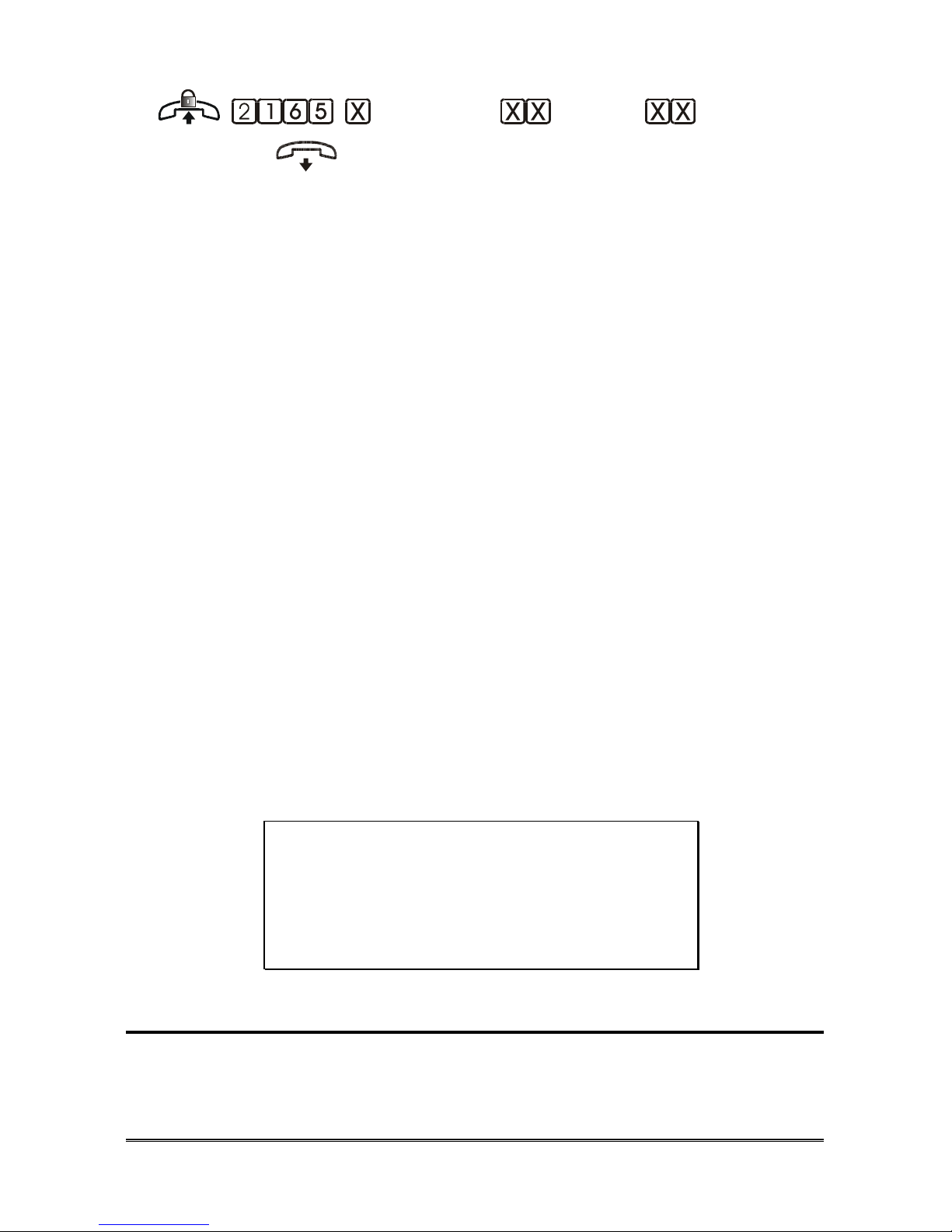
PROGRAMMINGS Pagina 93
(profile) (line) (message)
(confirm)
Pick up the handset of the system administrator extension (401).
Dial the code 2165.
Dial:
0 DAY profile
1 NIGHT profile
2 CUSTOM profile
3 All profiles
Dial the line number:
01 Analogue line L01
02 Analogue line L02
03 Analogue line L03
04 Analogue line L04
11 VIP1 line
12 VIP2 line
13 VIP3 line
14 VIP4 line
15 VIP5 line
16 VIP6 line
17 VIP7 line
18 VIP8 line
Dial the message index between 11 and 30 or 91 and 92.
Wait for the confirmation tone and hang up.
Note: only messages enabled for use, or compound messages can be
chosen.
ATTENTION:
if a IVR service menu is already assigned to
the line, the chosen DISA message will
substitute the menu prompting message and
for next calls DISA service will answer instead
of IVR.
DISA programming
Allows the activation of the DISA service over each line.
DEFAULT: not enabled over any of the lines and for any of the profiles.
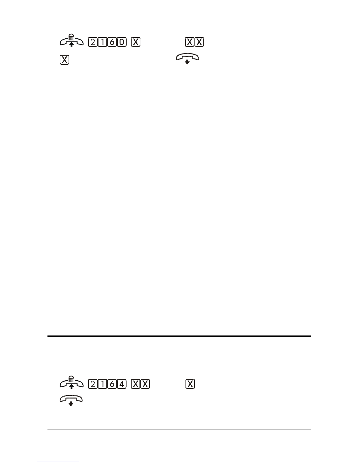
Pagina 94 PROGRAMMINGS
(profile) (line)
( activation) (confirm)
Pick up the handset of the system administrator extension (401).
Dial the code 2160.
Dial:
0 DAY profile
1 NIGHT profile
2 CUSTOM profile
3 All profiles
Dial the line number:
01 Analogue line L01
02 Analogue line L02
03 Analogue line L03
04 Analogue line L04
11 VIP1 line
12 VIP2 line
13 VIP3 line
14 VIP4 line
15 VIP5 line
16 VIP6 line
17 VIP7 line
18 VIP8 line
Dial:
0 to DISABLE the service
1 to ENABLE the service
Wait for the confirmation tone and hang up.
Delayed DISA programming
Allows activating the delayed DISA service over each real line.
Analogue Lines
DEFAULT: not enabled over any of the lines.
(trunk) (activation) (confirm)
Pick up the handset of the system administrator extension (401).
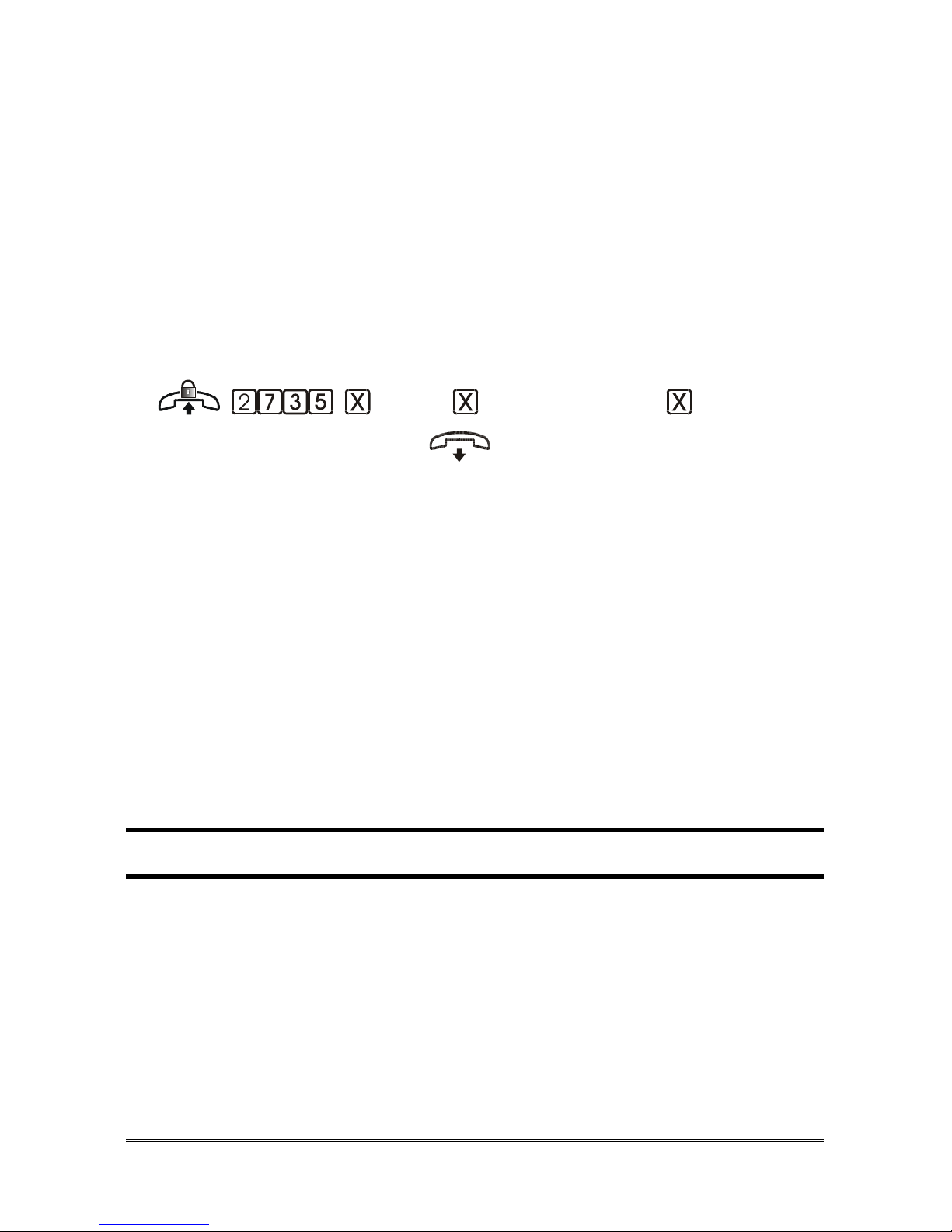
PROGRAMMINGS Pagina 95
Dial the code 2164.
Dial the line number (01~04).
Dial:
0 to DISABLE the service
1 to ENABLE the service
Wait for the confirmation tone and hang up.
Note: the delayed DISA service can be activated only over real
lines, regardless of the profile used.
ISDN Lines
DEFAULT: not enabled over any of the numbers in MSN table of both BRIs.
(BRI) (location 1~8)
(activation) (confirm)
Pick up the handset of the system administrator extension (401).
Dial the code 2735.
Dial:
1 BRI T01
2 BRI T02
Dial the location in the table (from 1 to 8).
Dial:
0 to DISABLE the service
1 to ENABLE the service
Wait for the confirmation tone and hang up.
A
UTOMATIC OPERATOR
(IVR)
The automatic operator allows you to browse through 10 customisable menus.
Each menu allows various operations: calling extensions, playing messages,
switching from one menu to the other, activating relays for remote control etc.
Each menu consists of:
• a customisable prompting message indicating the actions available in
that menu;
• up to 12 operations to be performed, each corresponding to the
telephone buttons.
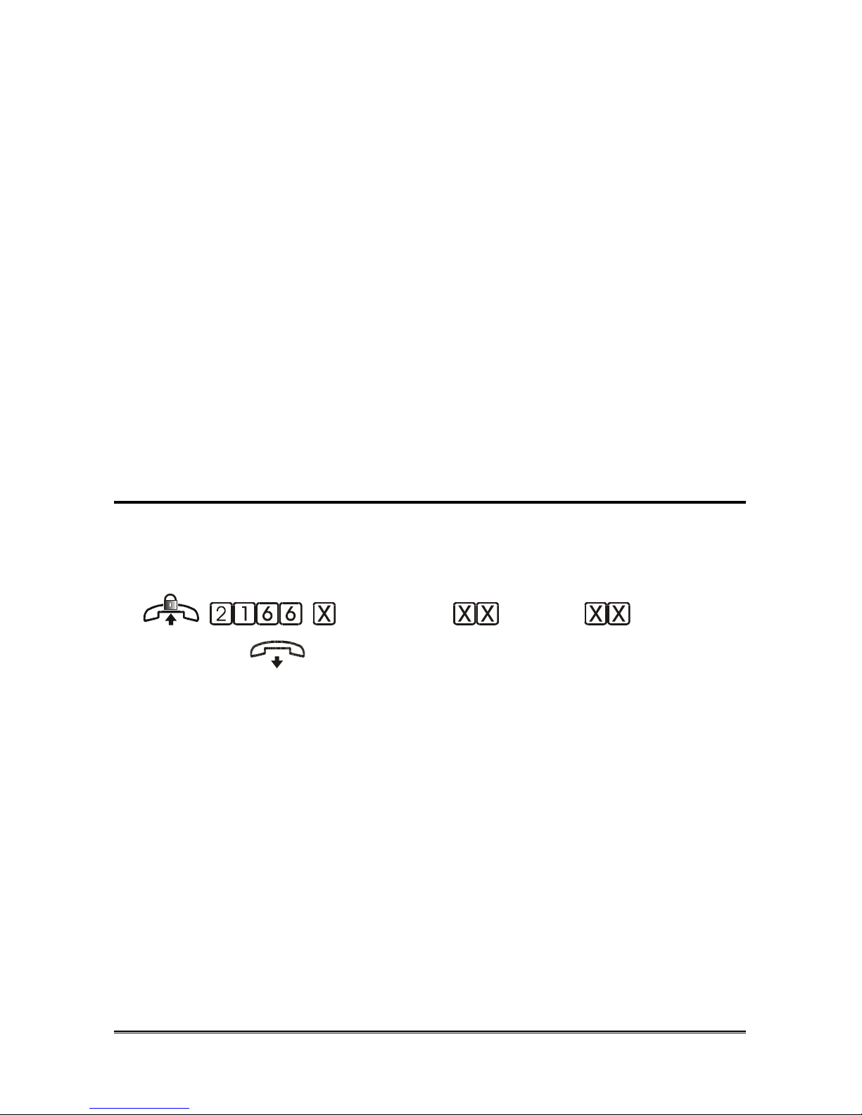
Pagina 96 PROGRAMMINGS
DEFAULT:
- menus 01~09: no prompting message, no operation assigned to the buttons,
except for the * button, which allows recalling the control menu (menu 10).
- menu 10:
. prompting message: Control menu (message 06)
. 0 button: allows disabling a relay. The index of the relay must be entered
after having pressed 0;
. 1 button: allows enabling a relay. The index of the relay must be entered
after having pressed 1;
. 2 button: allows enabling a relay for 1 second (programmable). The
index of the relay must be entered after having pressed 2;
. 6 button: turns the handsfree of an extension on. The extension number
must be entered after having pressed 6;
. # button: allows remote access to programming. The installer password
must be entered after pressing #.
Assigning a IVR menu to a line
This procedure assigns an IVR menu to a line for each profile.
Note: to carry out this procedure, the menus must be appropriately
programmed (see following paragraphs).
(profile) (line) (menu)
(confirm)
Pick up the handset of the system administrator extension (401).
Dial the code 2166.
Dial:
0 DAY profile
1 NIGHT profile
2 CUSTOM profile
3 All profiles
Dial the line number:
01 Analogue line L01
02 Analogue line L02
03 Analogue line L03
04 Analogue line L04
11 VIP1 line
12 VIP2 line
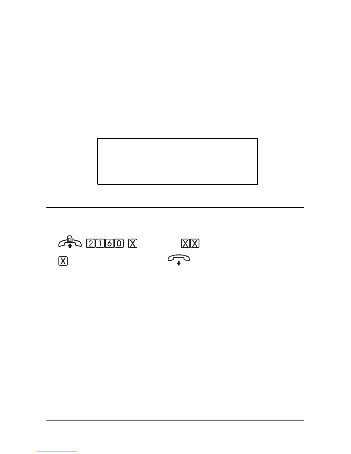
PROGRAMMINGS Pagina 97
13 VIP3 line
14 VIP4 line
15 VIP5 line
16 VIP6 line
17 VIP7 line
18 VIP8 line
99 All lines
Dial the index of the menu to be assigned (1~10).
Wait for the confirmation tone and hang up.
Note: the value 99 can be entered as “line”, in order to assign the
same menu to all six lines.
ATTENTION:
if a DISA service is already assigned to the
line, the IVR prompting message will
substitute the DISA one and for next calls IVR
service will answer instead of DISA.
Automatic operator (IVR) programming
Allows the activation of the IVR service over each line.
DEFAULT: not enabled over any of the lines and for any of the profiles.
(profile) (line)
(activation) (confirm)
Pick up the handset of the system administrator extension (401).
Dial the code 2160.
Dial:
0 DAY profile
1 NIGHT profile
2 CUSTOM profile
3 All profiles
Dial the line number:
01 Analogue line L01
02 Analogue line L02
03 Analogue line L03
04 Analogue line L04
11 VIP1 line
12 VIP2 line
13 VIP3 line

Pagina 98 PROGRAMMINGS
14 VIP4 line
15 VIP5 line
16 VIP6 line
17 VIP7 line
18 VIP8 line
Dial:
0 to DISABLE the service
1 to ENABLE the service
Wait for the confirmation tone and hang up.
Assign the menu prompting message
Allows assigning a prompting message to each menu.
(menu) (message) (confirm)
Pick up the handset of the system administrator extension (401).
Dial the code 2802.
Enter the menu index (01~10).
Enter the prompting message index (06, 14~30 o 91~92).
Wait for the confirmation tone and hang up.
Note: only messages enabled for use, or compound messages can be
chosen. System message (01~05 and 07~13 ) cannot be
chosen.
Deleting the assignation
(menu)( confirm)
Pick up the handset of the system administrator extension (401).
Dial the code 2801.
Enter the menu index (01~09).
Wait for the confirmation tone and hang up.
Note: removing the message assigned to menu 10 is not allowed
(“Control menu”).

PROGRAMMINGS Pagina 99
Prompting message recording/playback
Allows customising and playing back the prompting message of a menu.
(menu) (action) |
Pick up the handset of the system administrator extension (401).
Dial the code 2804.
Enter the menu index (01~10)
Dial:
0 to record
1 to play back
Press the R (flash) button, or hang up to end the procedure.
Note: once exceeded the maximum recording time, you will hear a
confirmation tone.
Note: in the event the prompting message is a compound message,
in order to customise it, it is necessary to record the single
messages (see “Errore. L'origine riferimento non è stata
trovata./deleting” at page 86)
Defining menu events
Allows defining the operations included in a menu, and the relevant buttons
that the caller can press. Each menu must have a previously assigned prompting
message.
(menu) (event) (operation)
(parameter) (confirm)
Pick up the handset of the system administrator extension (401).
Dial the code 2803.
Enter the menu index (01~10).
Enter the event:
00 the external user selects the 0 button
01 the external user selects the 1 button
…..
09 the external user selects the 9 button
0* the external user selects the * button
0# the external user selects the # button

Pagina 100 PROGRAMMINGS
10 the external user makes no selection and the menu message
is over
Enter the operation to be performed:
00 No action
01 Call to extension ( )
02 Call to FAX extension
03 DISA call
04 Incoming call
05 Incoming call over VIP ( ) line
06 Message ( ) playback and incoming call
07 Message ( ) playback ( ) and free line
08 Repeat prompting message
09 Menu ( ) recall ( )
10 Menu ( ) recall, with user PWD
11 Relay ( ) ON
12 Relay ( ) OFF
13 Relay ( ) impulse
14 Access to remote programmer with installer PWD
150 Handsfree ambient listening
151 Handsfree ambient listening ( )
Enter the parameter if required by the function ( ).
Wait for the confirmation tone and hang up.
The parameter is available only for some operations and it assumes different
values, according to the chosen operation.
No action
No action assigned to this selection.
Call to extension ( )
The call is diverted to the extension (401~412) set by
the parameter.
Call to FAX
extension
The call is diverted to the extension defined as FAX
extension.
DISA call
The caller can select the extension desired.
Incoming call
The incoming call is diverted to the extensions
enabled to ring over that line.
Incoming call over
VIP line ( )
The incoming call is diverted to the extensions
enabled to ring over the VIP line (1~8) defined by the
parameter (11~18).
 Loading...