


20/03/2017
Alarm system for elevators
QUICK GUIDES:
HELPY QUICK INTL
HELPY QUICK-TL INTL
ST61 INTL
DESCRIPTION Page 2
DESCRIPTION
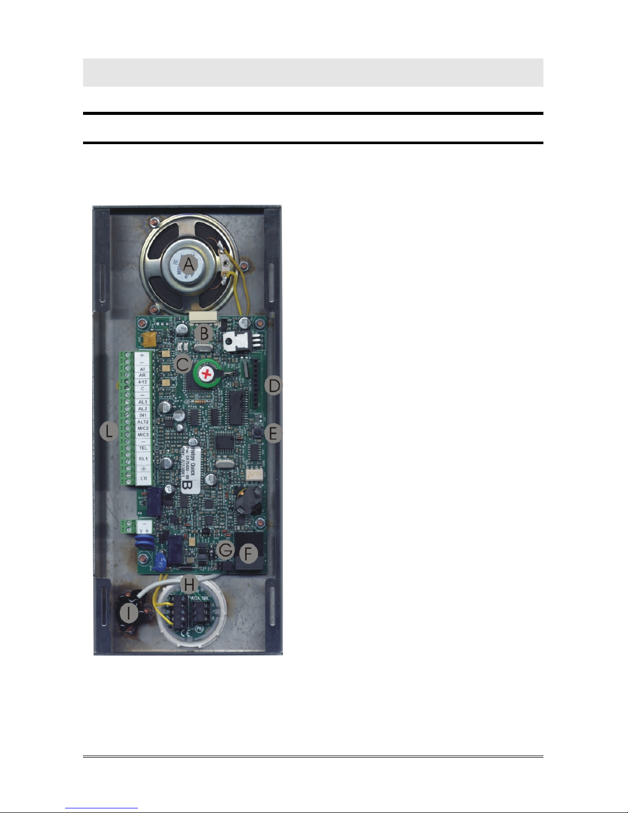
HELPY QUICK
A Built-in loudspeaker
B Connector for Esse-ti power
supply (12Vdc)
C LED indicating device operation (red)
LED indicating GSM200 signal
strength (green)
D Connector for FlashKey
E Reset pushbutton
F RJ45 connector for GSM200 module
G Jumpers for Telephone Line /
GSM200 Module selection
H Pushbutton (two contacts):
.C2: common
.NO2: normally open
.NC2: normally closed
I Built-in microphone
L Terminal blocks

Page 3 DESCRIPTION
Terminal blocks:
+ 12Vdc power supply input or 12Vdc output (max. 100mA,
if present Esse-ti power supply)
- Negative pole
AI Given alarm indicator light
AR Received alarm indicator light
+12 12Vdc output (max. 100mA)
C Common terminal for inputs AL1 and IN1
- Negative pole
AL1 Alarm input 1
AL2 Alarm input 2
IN1 Filter input
ALT2 Output for connecting loudspeaker of passive handsfree
terminal
MIC2 Input for connecting microphone of passive handsfree or
single microphone
MIC3 Input for connecting microphone of passive handsfree or
single microphone
- Negative pole
TEL Local Telephone
RL1 Relay
Ground terminal for telephone line
LTI Telephone line input
- Negative pole
V + Pit active handsfree
DESCRIPTION Page 4
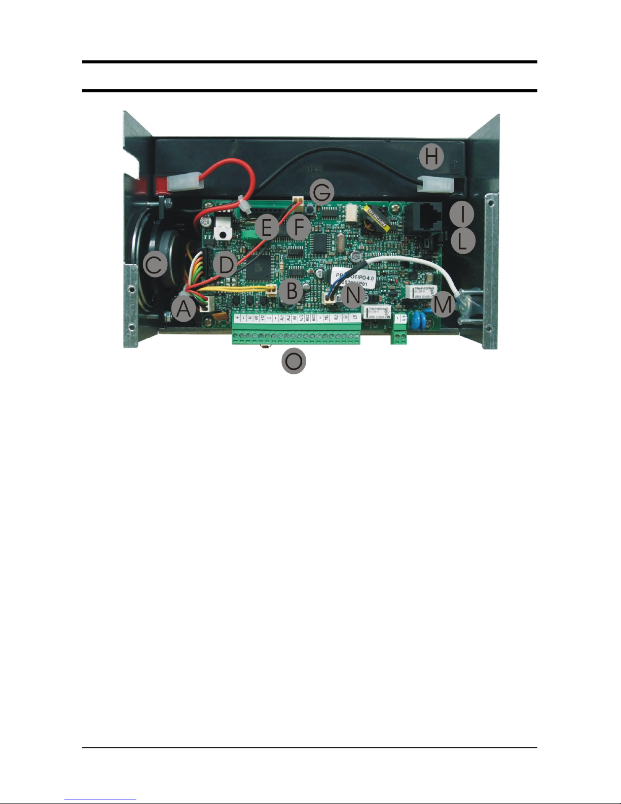
HELPY QUICK-TL
A Connector for external LEDs
B Connector for built-in loudspeaker
C Built-in loudspeaker
D Connector for internal power supply
E Connector for FlashKey
F Connector for external reset pushbutton
G Reset pushbutton
H Battery
I RJ45 connector for GSM200 module
L Jumpers for Telephone Line / GSM200 Module selection
M Built-in microphone
N Connector for built-in microphone
O Terminal blocks
Page 5 DESCRIPTION
Terminal blocks:
+ 12Vdc output (max. 100mA)
- Negative pole
AI Given alarm indicator light
AR Received alarm indicator light
+12 12Vdc output (max. 100mA)
C Common terminal for inputs AL1 and IN1
- Negative pole
AL1 Alarm input 1
AL2 Alarm input 2
IN1 Filter input
ALT2 Output for connecting loudspeaker of passive handsfree
terminal
MIC2 Input for connecting microphone of passive handsfree or
single microphone
MIC3 Input for connecting microphone of passive handsfree or
single microphone
- Negative pole
TEL Local telephone
RL1 Relay
Ground terminal for telephone line
LTI Telephone line input
- Negative pole
V + Pit active handsfree
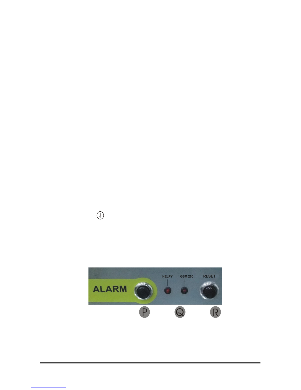
P Alarm pushbutton
Q LEDs indicating device operation and GSM200 signal
strength
R End alarm pushbutton (Reset pushbutton)
DESCRIPTION Page 6
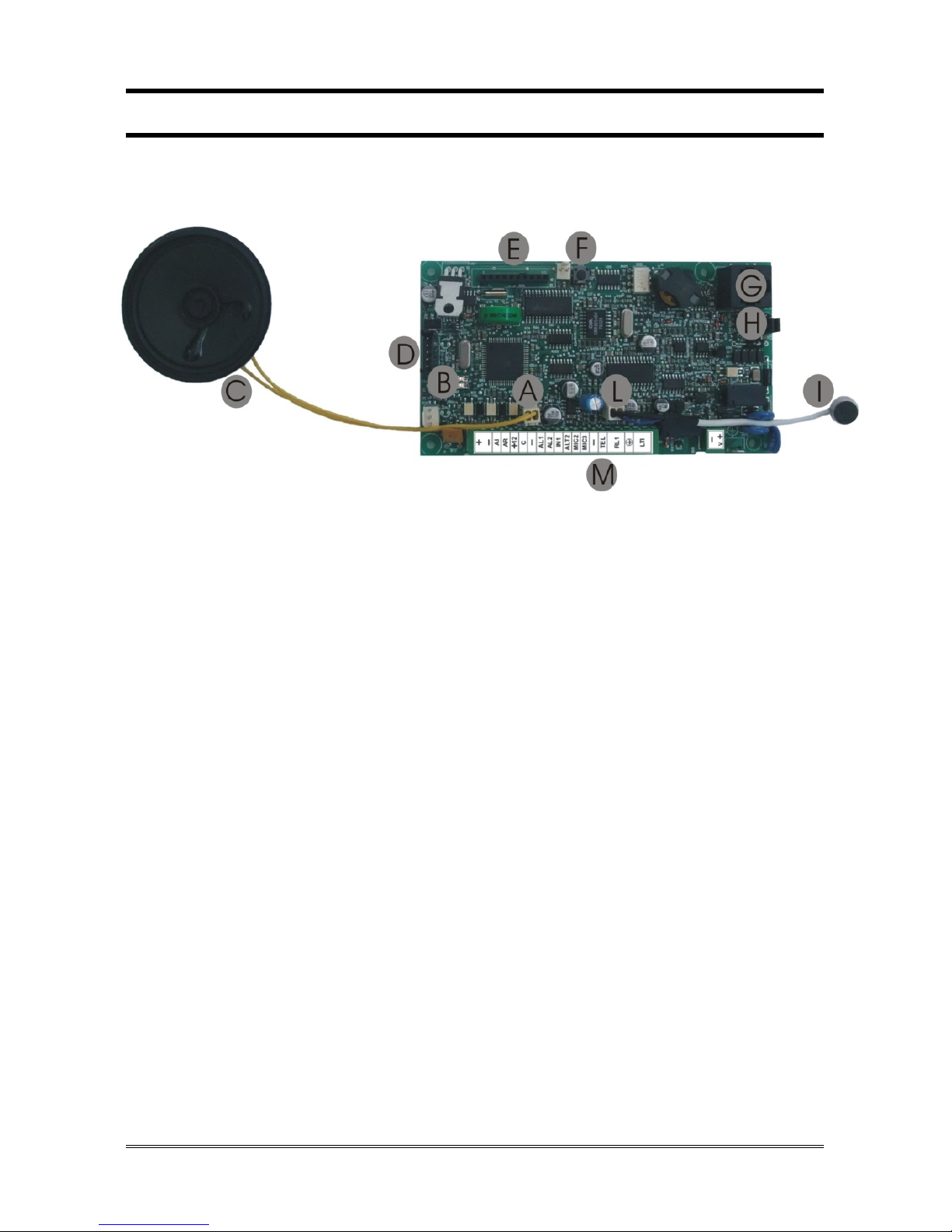
ST61
A Connector for built-in loudspeaker
B LED indicating device operation (red)
LED indicating GSM200 signal strength (green)
C Built-in loudspeaker
D Connector for Esse-ti power supply (12Vdc)
E Connector for FlashKey
F Reset pushbutton
G RJ45 connector for GSM200 module
H Jumpers for Telephone Line / GSM200 Module selection
I Built-in microphone
L Connector for built-in microphone
M Terminal blocks

Page 7 DESCRIPTION
Terminal blocks:
+ 12Vdc power supply input or 12Vdc output (max. 100mA,
if present Esse-ti power supply)
- Negative pole
AI Given alarm indicator light
AR Received alarm indicator light
+12 12Vdc output (max. 100mA)
C Common terminal for inputs AL1 and IN1
- Negative pole
AL1 Alarm input 1
AL2 Alarm input 2
IN1 Filter input
ALT2 Output for connecting loudspeaker of passive handsfree
terminal
MIC2 Input for connecting microphone of passive handsfree or
single microphone
MIC3 Input for connecting microphone of passive handsfree or
single microphone
- Negative pole
TEL Local Telephone
RL1 Relay
Ground terminal for telephone line
LTI Telephone line input
- Negative pole
V + Pit active handsfree
CONNECTING THE TELEPHONE LINE Page 8
CONNECTING THE TELEPHONE LINE
HELPY QUICK – ST61
The device allows the connection of a PSTN line or GSM line by means of the
GSM200 module or a traditional GSM interface.
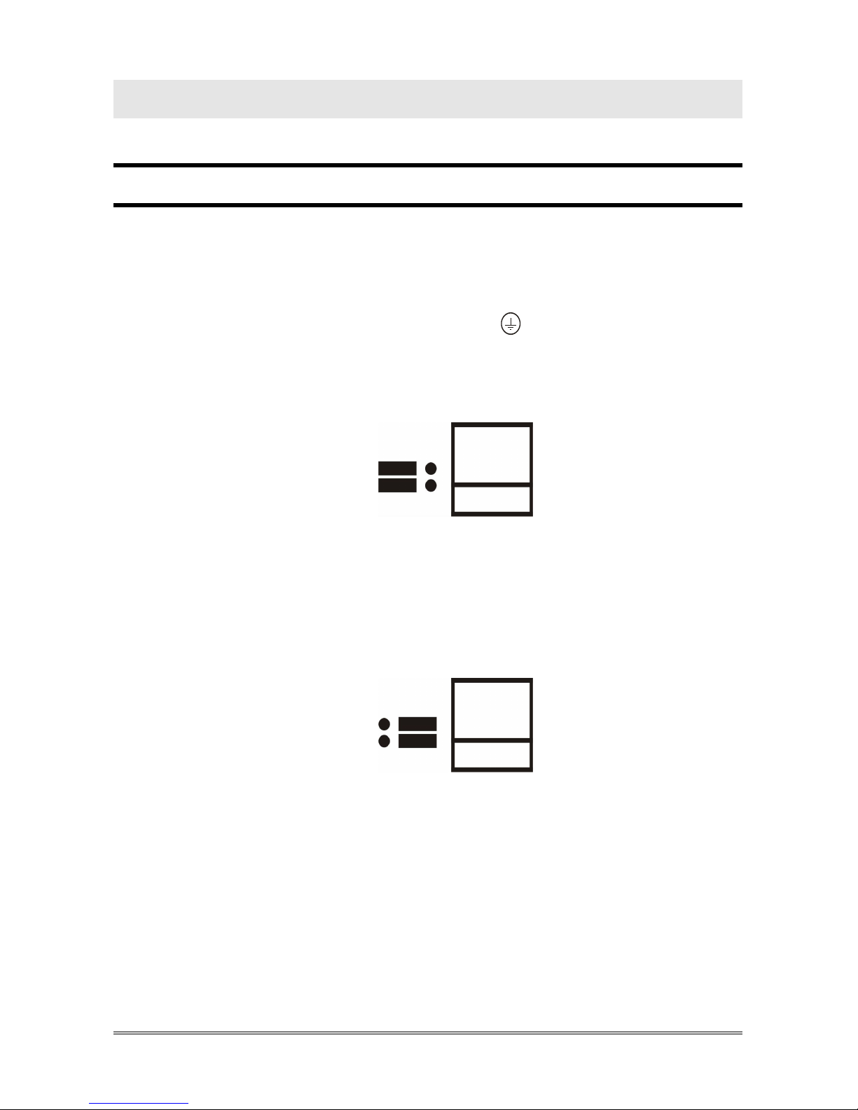
PSTN line or traditional GSM interface
Connect the ground terminal (indicated by ) to a ground socket in order
to increase the telephone line protection.
Make sure that Jumpers (G in the picture at page 2 or H in the picture at
page 6) are set in the position shown below (default setting).
Connect the telephone line to the LTI.
GSM200 Module
Please see also the GSM200 User Manual.
Make sure that Jumpers (G in the picture at page 2 or H in the picture at
page 6) are set in the position shown below.
Connect the RJ45 connector (F in the picture at page 2 or G in the picture at
page 6) to the GSM200 module by means of the supplied cable.

Page 9 CONNECTING THE TELEPHONE LINE
HELPY QUICK-TL
The device allows the connection of a PSTN line or GSM line by means of the
GSM200 module or a traditional GSM interface.
PSTN line or traditional GSM interface
Connect the ground terminal (indicated by ) to a ground socket in order
to increase the telephone line protection.
Make sure that Jumpers (L in the picture at page 4) are set in the position
shown below (default setting).
Connect the telephone line to the LTI.
GSM200 Module
Please see also the GSM200 User Manual.
Make sure that Jumpers (L in the picture at page 4) are set in the position
shown below.
Connect the RJ45 connector (I in the picture at page 4) to the GSM200
module by means of the supplied cable.

CONNECTING EMERGENCY PUSHBUTTON AL1 AND FILTER IN1 Page 10
CONNECTING EMERGENCY
PUSHBUTTON AL1 AND FILTER IN1
HELPY QUICK-TL – ST61
It is possible to connect (inside the elevator car) voltage free contact
pushbuttons or powered pushbuttons.
Voltage free contact pushbuttons
Connect the filter contact to IN1 terminal and – (negative pole).

Page 11 CONNECTING EMERGENCY PUSHBUTTON AL1 AND FILTER IN1
Powered pushbuttons (12~ 24Vdc)
Connect the filter contact to IN1 terminal and – (negative pole).
Connect the filter contact to IN1 terminal and +12V terminal.

WIRING DIAGRAMS Page 12
WIRING DIAGRAMS
HELPY QUICK

Page 13 WIRING DIAGRAMS
HELPY QUICK-TL
Wiring diagram with active handsfree terminal in
the pit

WIRING DIAGRAMS Page 14
Wiring diagram with passive handsfree terminal
in the elevator car bottom

Page 15 WIRING DIAGRAMS
ST61
Wiring diagram with active handsfree terminal in
the pit

WIRING DIAGRAMS Page 16
Wiring diagram with passive handsfree terminal
in the elevator car bottom

Page 17 CORRECT OPERATION CHECKLIST
CORRECT OPERATION CHECKLIST
1. PROGRAMMING
Access to programming: lift the local telephone handset and dial
.
You will hear the dialling tone (one longer tone followed by a shorter
tone).
Only if GSM200 module is present: dial .
Program a telephone number for the emergency-call alarm:
dial <telephone number> .
Record the identification message of the specific elevator (max. 22
seconds), which is meant to contain all necessary information
concerning the elevator location: dial , pronounce the
message and hang up.
To listen again to the previous message dial: .
Make an external call to check the telephone line presence: dial and
digit the telephone number to make a test call.
2. ALARM PROCEDURE CHECK
Press the emergency button.
The emergency call will be made.
3. ANSWERING AN ALARM
-1st mode: handsfree connection by “Handsfree activation” code (factory
default)
Answer by the called party.
The voice messages will be heard.
Press to speak with the trapped person.
-2nd mode: automatic handsfree connection
Answer by the called party.
Speak with the trapped person.
Remark: you can choose the 1st or the 2
nd
mode with the “Handsfree
connection mode” programming (code 78).

CORRECT OPERATION CHECKLIST Page 18
4. RESETTING AN ALARM
-1nd mode: reset by “End” code (factory default)
Press to end the alarm.
-2
st
mode: automatic reset
Hang up or press to end the alarm.
Remark: you can choose the 1st or the 2nd mode with the “Alarm
reset mode” programming (code 77).
In case it should not be possible to stop the alarm procedure remotely (i.e. the
entered telephone number is incorrect) simply lift the handset of the local telephone
and dial * <Password> # (by factory default: .
How to use the reset pushbuttons
Use of the reset pushbuttons (E in the picture at page 2, G in the picture at page
4, R in the picture at page 5, F in the picture at page 6):
Pressing shortly
Allows to interrupt an alarm call.
By pressing shortly you get the same result as lifting the handset of the local
telephone and entering : * <Password> #.
Pressing longer (15 seconds)
Allows to reset the device.
By pressing longer, the device will be re-started with no need to disconnect
the power supply.
The reset operation does not alert the previously set parameters.

Page 19 PROGRAMMING
PROGRAMMING
In the tables below:
INST indicates that the programming procedure is allowed for the installer;
OPER indicates that the programming procedure is allowed for the operator;
factory default values are highlighted in bold.
Basic programming
BASIC PROGRAMMING
ACCESS TO
PROGRAMMING
<INSTALLER or OPERATOR PASSWORD>
(by default: )
EXITING THE
PROGRAMMING
<INSTALLER or OPERATOR PASSWORD>
(by default: )
TYPE OF
TELEPHONE
LINE
(INST)
PSTN line or traditional GSM interface
GSM200 module
TELEPHONE
NUMBERS
(INST)
(position
from 01
to 12)
SOURCE RECEIVER
…
(X…X =
telephone
number,
max 20
digits)
emergency-
call button
ADEMCO
technological
alarms
USER
periodic
test call
ESSE-TI
-
CLI
alarm sent
alert
notification
SMS
(only with
GSM200)
alarm
terminated
alert
notification
P100

PROGRAMMING Page 20
BASIC PROGRAMMING
DELETING
TELEPHONE
NUMBER
(INST)
(position from
01 to 12)
HANDSFREE
CONNECTION
MODE
(INST)
handsfree activation by
“Handsfree activation” code
automatic handsfree activation
ALARM RESET
MODE
(INST)
automatic reset
alarm reset by “End” code
DATE
(INST)
WEEKDAY
(dd) (mm) (yy)
SUNDAY
MONDAY
TUESDAY
WEDNESDAY
THURSDAY
FRIDAY
SATURDAY
TIME
(INST)
(hhmm; from 0000 to 2359)
RECORD
MESSAGES
(INST)
identification message
(max. 22 sec.)
(beep)
record and
hang up
courtesy message
(max. 22 sec.)
LISTEN TO
MESSAGES
(INST/OPER)
identification message
(listen)
courtesy message
INSTALLATION
TYPE
(INST)
handsfree terminals only on the roof, in the
elevator car, in the bottom of the elevator car
active handsfree terminal also in the pit
DEAD BATTERY
ALARM
(INST)
disabled alarm
enabled alarm
NO MAINS
POWER SUPPLY
ALARM
(INST)
disabled alarm
from 01 to 99 = enabled alarm with XX minutes
delay

Page 21 PROGRAMMING
BASIC PROGRAMMING
ADEMCO / P100
PROTOCOL ID
(INST)
max 10-digits ID:
...
[]
ESSE-TI
PROTOCOL ID
(INST)
10-digits ID:
AUTOMATIC TEST
DATA
(INST)
Frequency
(days, from 1 to 9; factory default 3)
Time
(hhmm; from 0000 to 2359)
Automatic
test alarm
automatic test disabled
automatic test enabled
Make a test call
manually
BUILT-IN
HANDSFREE
VOLUME
(INST/OPER)
... (loudspeaker’s volume; factory default 3)
PIT HANDSFREE
VOLUME
(INST/OPER)
... (loudspeaker’s volume; factory default 3)
MESSAGES
VOLUMES
(INST/OPER)
... (volume; factory default 2)
LISTENING TO
PROGRAMMING
... (prefix programming code)
RESTORING
FACTORY
DEFAULT
(INST)

PROGRAMMING Page 22
Advanced programming
ADVANCED PROGRAMMING
CHANGING THE
INSTALLER
PASSWORD
(INST)
… (old) .. (new) .. (new)
CHANGING THE
OPERATOR
PASSWORD
(INST)
…(old) .. (new) .. (new)
LANGUAGE
(INST)
Italian
English
German
French
Polish
Portuguese
Russian
Spanish
TONE DECODER
SETTING
(INST)
Italy/Switzerland/Portugal/Poland/Bulgaria
England
Israel
Greece
Austria (digital)
Germany
France
Australia
Russia/Hungary
Netherlands/Croatia
EMERGENCY
BUTTON AL1
NORMALLY
OPEN/CLOSED
(INST)
normally closed
normally open
EMERGENCY
BUTTON DELAY
(INST)
(seconds, from 0 to 9; factory default 2)

Page 23 PROGRAMMING
ADVANCED PROGRAMMING
FILTER
ACTIVATION
(INST/OPER)
disabled
enabled
FILTER INPUT
NC/NO
(INST/OPER)
normally closed
normally open
“ACKNOWLEDGE”
CODE
(INST)
… (from 1 to 3 digits; factory default 5)
[]
“HANDSFREE
ACTIVATION”
CODE
(INST)
… (from 1 to 3 digits; factory default 0)
[]
“END” CODE
(INST)
… (from 1 to 3 digits; factory default 9)
[]
“EXCLUSION”
CODE
(INST)
… (from 1 to 3 digits; factory default 1)
[]
HANDSFREE
CONNECTION
TIME UPON
ALARM
(INST)
(minutes, from 2 to 9)
NUMBER OF
CALLS TO THE
SAME
TELEPHONE
NUMBER FOR
EACH CALL CYCLE
(INST)
(calls from 1 to 9)
CALL CYCLES FOR
TECHNOLOGICAL
ALARMS AND
TEST CALLS
(INST)
(cycles from 0 to 9; 0 = 10 cycles;
factory default 3)
CALL CYCLES FOR
EMERGENCY
CALLS
(INST)
(cycles from 0 to 9; 0 = unlimited)
AUTOMATIC
ANSWER
(INST)
(ring number from 0 to 9; 0 = disabled;
factory default 1)

PROGRAMMING Page 24
ADVANCED PROGRAMMING
CONNECTION
TIME AFTER
AUTOMATIC
ANSWER
(INST)
(minutes, from 1 to 9)
OFFSET FLOOR
MESSAGES
(INST)
(offset, from 0 to 9)
RELAY SETTINGS
(INST)
same behavior as output AI
same behavior as output AR
active for mains failure
door opener
active as long as the emergency alarm
progresses
active as long as the buttons are pressed
RELAY
INTERMITTENCE
(INST)
steady-state
intermittent (500 ms ON / 500 ms OFF)
DTMF
GENERATOR
SETTINGS WITH
GSM200
(INST)
DTMF generated by GSM network
DTMF generated by autodialer
(DTMF duration = X * 50ms)
READING
GSM200 SIGNAL
LEVEL
(INST)
Listened or read digits Quality
0-12 No signal
13-18 Low signal
19-24 Medium signal
>24 High signal

Page 25 PROGRAMMING VIA SMS (ONLY WITH GSM200)
PROGRAMMING VIA SMS (ONLY WITH
GSM200)
All parameters programmable locally by the local telephone may also be set
via SMS.
Programming via SMS is possible by any mobile phone or other device
supporting SMS.
An SMS notifying that programming has been completed will be sent back by
the autodialer to the same telephone number that forwarded the programming
SMS.
WARNING
Programming outgoing SMS from the Internet may not be
successful if the requested format is not respected.
Programming message format
Each programming SMS must contain the password, allowing to access
programming, and the codes corresponding to the desired settings.
The message format is required to be as follows:
ET-HL3 *xxx# n…n n…n n…n
Where:
ET-HL3 : programming string start
*xxx# : password string (default xxx = 0)
n…n : programming code (e.g. to enable battery check: 521).
To set more than one parameter, enter the related codes in a sequence separated
by a space, make sure you do not overcome the max number of characters
allowed by a single SMS ( 160 characters).
Notification message format
SMS settings are acknowledged with return SMS generated by autodialer
saying which parameter is set. The acknowledge SMS is returned as soon as the
setting SMS is received.
The message format is required to be as follows:
IP DTv DTv DTv OP
Where:
IP : programming access acknowledge (In Prog)

PROGRAMMING VIA SMS (ONLY WITH GSM200) Page 26
DTv: : string setting acknowledge (v = setting)
OP : programming exit acknowledge (Out Prog).
In case a telephone number has been programmed, the string setting will have
the following format:
DTaNbNy…y
Where:
a: source
b: receiver
y…y: telephone number
In case a wrong setting has been entered , the acknowledge string ER will be
returned.
In case the password is wrong , you will receive the acknowledge string RL ER
followed by as many ER as the sent codes are.
Remark: settings may be displayed fully or partially in the
acknowledge SMS returned after programming, depending on
the characteristics of the SMS recipient devices.
Examples
Desired settings:
- date: Thursday 04/02/16
- hour: 21.15
- automatic test call: enabled
Programming message:
ET-HL3 *0# 364040216 352115 341
Notification message:
IP DT4040216 DT2115 DT1 OP
Desired settings:
- phone number 0717506066 in the first location associated with Emergency
call (source) under User mode (receiver)
- phone number 0717506105 in the second location associated with Automatic
test call (source) under Esse-ti protocol mode (recipient)
Programming message:
ET-HL3 *0# 2101120717506066# 2102330717506105#
Notification message:
IP DT1N2N0717506066 DT3N3N0717506105 OP

Page 27 USE
USE
In the tables below:
: lift the local telephone handset;
: lift the local telephone handset and dial to access programming.
Local
LOCAL USE
CONVERSATION
WITH THE CAR
CONVERSATION
CONVERSATION
WITH ONE
HANDSFREE
TERMINAL
HANDSFREES IN ELEVATOR CAR
PIT ACTIVE HANDSFREE
DEACTIVATE ALL
OUTGOING CALLS
<TELEPHONE NUMBER>
RELAY
Remote use with autodialer in stand-by
Call the autodialer and wait for the answer.
After a short series of DTMF tones followed by the elevator identification
message, dial: <INSTALLER OR OPERATOR PASSWORD> (by
default: ).
Besides the programming, the following services are available:
REMOTE USE WITH AUTODIALER IN STAND-BY
CONVERSATION WITH ONE
HANDSFREE TERMINAL
HANDSFREES IN ELEVATOR CAR
PIT ACTIVE HANDSFREE
DEACTIVATE ALL
DOOR OPENER RELAY

Esse-ti s.r.l.
Via G. Capodaglio, 9
62019 Recanati (MC) – ITALY
Tel. +39 071 7506066
Fax +39 071 7506057
www.esse-ti.it
e-mail: support@esse-ti.it
 Loading...