

Esse-ti HELPY QUICK INTL, HELPY QUICK-TL INTL, ST61 INTL Quick Manual

20/03/2017
Alarm system for elevators
QUICK GUIDES:
HELPY QUICK INTL
HELPY QUICK-TL INTL
ST61 INTL
DESCRIPTION Page 2
DESCRIPTION
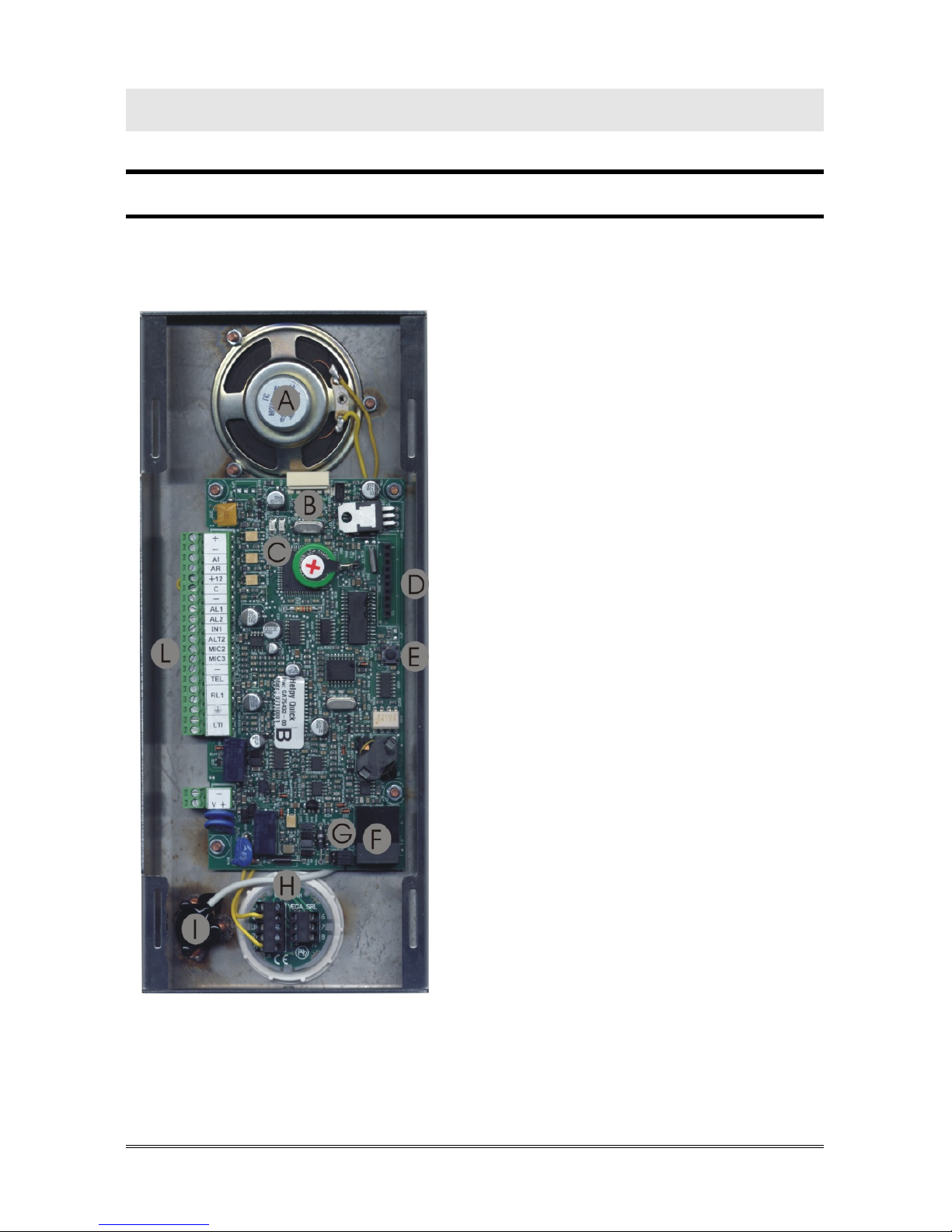
HELPY QUICK
A Built-in loudspeaker
B Connector for Esse-ti power
supply (12Vdc)
C LED indicating device operation (red)
LED indicating GSM200 signal
strength (green)
D Connector for FlashKey
E Reset pushbutton
F RJ45 connector for GSM200 module
G Jumpers for Telephone Line /
GSM200 Module selection
H Pushbutton (two contacts):
.C2: common
.NO2: normally open
.NC2: normally closed
I Built-in microphone
L Terminal blocks

Page 3 DESCRIPTION
Terminal blocks:
+ 12Vdc power supply input or 12Vdc output (max. 100mA,
if present Esse-ti power supply)
- Negative pole
AI Given alarm indicator light
AR Received alarm indicator light
+12 12Vdc output (max. 100mA)
C Common terminal for inputs AL1 and IN1
- Negative pole
AL1 Alarm input 1
AL2 Alarm input 2
IN1 Filter input
ALT2 Output for connecting loudspeaker of passive handsfree
terminal
MIC2 Input for connecting microphone of passive handsfree or
single microphone
MIC3 Input for connecting microphone of passive handsfree or
single microphone
- Negative pole
TEL Local Telephone
RL1 Relay
Ground terminal for telephone line
LTI Telephone line input
- Negative pole
V + Pit active handsfree
DESCRIPTION Page 4
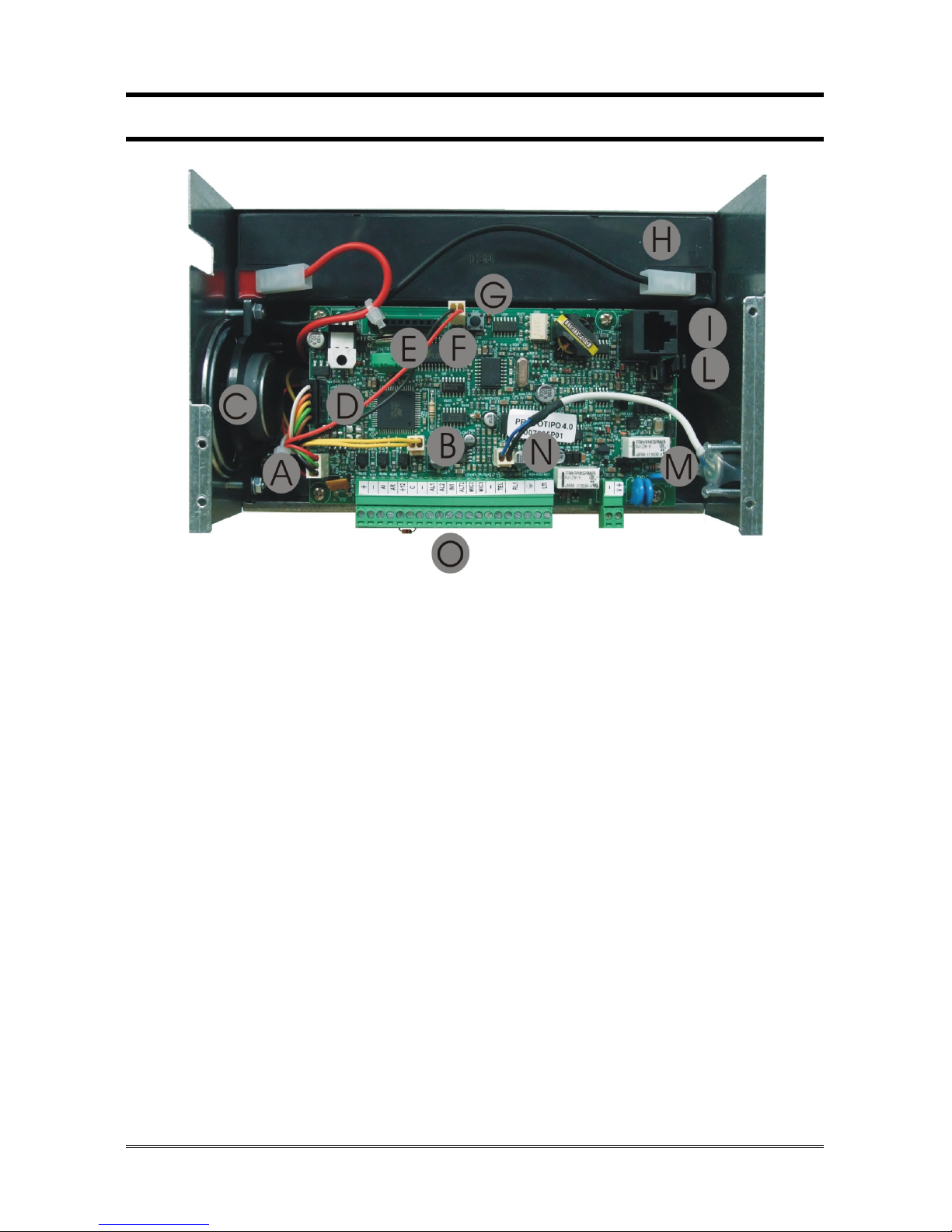
HELPY QUICK-TL
A Connector for external LEDs
B Connector for built-in loudspeaker
C Built-in loudspeaker
D Connector for internal power supply
E Connector for FlashKey
F Connector for external reset pushbutton
G Reset pushbutton
H Battery
I RJ45 connector for GSM200 module
L Jumpers for Telephone Line / GSM200 Module selection
M Built-in microphone
N Connector for built-in microphone
O Terminal blocks
Page 5 DESCRIPTION
Terminal blocks:
+ 12Vdc output (max. 100mA)
- Negative pole
AI Given alarm indicator light
AR Received alarm indicator light
+12 12Vdc output (max. 100mA)
C Common terminal for inputs AL1 and IN1
- Negative pole
AL1 Alarm input 1
AL2 Alarm input 2
IN1 Filter input
ALT2 Output for connecting loudspeaker of passive handsfree
terminal
MIC2 Input for connecting microphone of passive handsfree or
single microphone
MIC3 Input for connecting microphone of passive handsfree or
single microphone
- Negative pole
TEL Local telephone
RL1 Relay
Ground terminal for telephone line
LTI Telephone line input
- Negative pole
V + Pit active handsfree
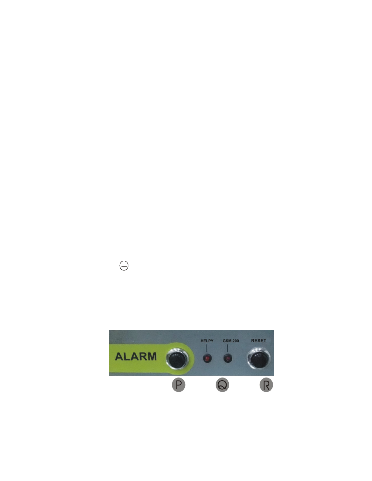
P Alarm pushbutton
Q LEDs indicating device operation and GSM200 signal
strength
R End alarm pushbutton (Reset pushbutton)
DESCRIPTION Page 6
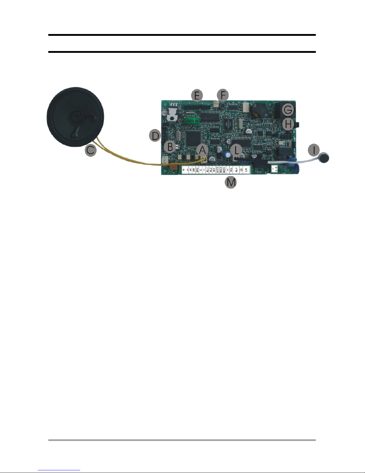
ST61
A Connector for built-in loudspeaker
B LED indicating device operation (red)
LED indicating GSM200 signal strength (green)
C Built-in loudspeaker
D Connector for Esse-ti power supply (12Vdc)
E Connector for FlashKey
F Reset pushbutton
G RJ45 connector for GSM200 module
H Jumpers for Telephone Line / GSM200 Module selection
I Built-in microphone
L Connector for built-in microphone
M Terminal blocks

Page 7 DESCRIPTION
Terminal blocks:
+ 12Vdc power supply input or 12Vdc output (max. 100mA,
if present Esse-ti power supply)
- Negative pole
AI Given alarm indicator light
AR Received alarm indicator light
+12 12Vdc output (max. 100mA)
C Common terminal for inputs AL1 and IN1
- Negative pole
AL1 Alarm input 1
AL2 Alarm input 2
IN1 Filter input
ALT2 Output for connecting loudspeaker of passive handsfree
terminal
MIC2 Input for connecting microphone of passive handsfree or
single microphone
MIC3 Input for connecting microphone of passive handsfree or
single microphone
- Negative pole
TEL Local Telephone
RL1 Relay
Ground terminal for telephone line
LTI Telephone line input
- Negative pole
V + Pit active handsfree
CONNECTING THE TELEPHONE LINE Page 8
CONNECTING THE TELEPHONE LINE
HELPY QUICK – ST61
The device allows the connection of a PSTN line or GSM line by means of the
GSM200 module or a traditional GSM interface.
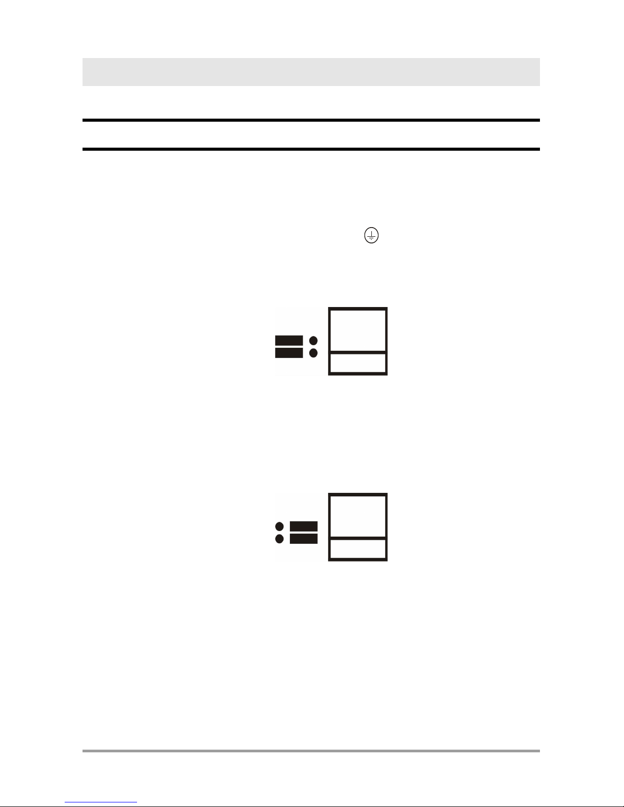
PSTN line or traditional GSM interface
Connect the ground terminal (indicated by ) to a ground socket in order
to increase the telephone line protection.
Make sure that Jumpers (G in the picture at page 2 or H in the picture at
page 6) are set in the position shown below (default setting).
Connect the telephone line to the LTI.
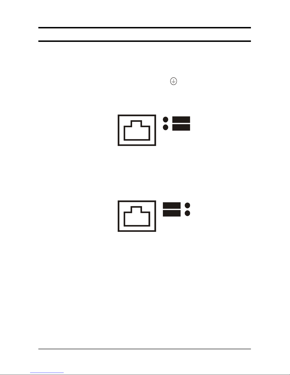
GSM200 Module
Please see also the GSM200 User Manual.
Make sure that Jumpers (G in the picture at page 2 or H in the picture at
page 6) are set in the position shown below.
Connect the RJ45 connector (F in the picture at page 2 or G in the picture at
page 6) to the GSM200 module by means of the supplied cable.
Page 9 CONNECTING THE TELEPHONE LINE
HELPY QUICK-TL
The device allows the connection of a PSTN line or GSM line by means of the
GSM200 module or a traditional GSM interface.
PSTN line or traditional GSM interface
Connect the ground terminal (indicated by ) to a ground socket in order
to increase the telephone line protection.
Make sure that Jumpers (L in the picture at page 4) are set in the position
shown below (default setting).
Connect the telephone line to the LTI.
GSM200 Module
Please see also the GSM200 User Manual.
Make sure that Jumpers (L in the picture at page 4) are set in the position
shown below.
Connect the RJ45 connector (I in the picture at page 4) to the GSM200
module by means of the supplied cable.
 Loading...