

Page 1

13/01/2016
GSM/GPRS/GPS TELECARE SYSTEM
User Quick Guide
HELPY OOPS
Page 2

2
DESCRIPTION
Helpy Oops is an emergency device specifically designed for personal
security, especially in relation to people with cognitive or mobility
impairment, either temporary or permanent.
Equipped with GSM, GPRS and GPS modules, Helpy Oops allows the
remote handsfree communication, to send emergency calls after an
accidental fall or by pressing a pushbutton, to send alarms if the end
user crosses the borders of geographical safety areas, to detect the
position of the end user in trouble.
Page 3

3
WARNINGS AND PRECAUTIONS
Helpy Oops has been designed , developed and manufactured according to specific
criteria for quality, reliability and top performance adopted by the producer; it must be
used as prescribed in the present user manual. Esse-ti declines any liability arising from
the improper use of the product. Warning: for correct operation, it is recommended to
use the product in areas where GSM coverage is guaranteed by the SIM card provider.
Esse-ti declines any liability for improper device operation due to mobile network
failures. The SIM card must always be topped up so as to guarantee a sufficient credit for
emergency calls. Make sure all above mentioned conditions are met with before using
the device. Warning: Helpy Oops is a personal device suitable for notifying emergency
and rescue situations which does not relieve users from adopting all other necessary
measures prescribed under the specific case.
Page 4

4
CONFORMITY DECLARATION
Esse-ti S.r.l. having its seat in Via G. Capodaglio 9, 62019 Recanati (MC), Italy,
hereby declares that the device HELPY OOPS is manufactured in Italy and
complies with the following regulations:
- EN 50385:2002 GSM
- EN 60950-1:2006 +A11:2009 +A1:2010 +A12:2011 +A2:2013
- EN 301489-1 V1.9.2
- EN 301489-3 V1.6.1
- EN 301489-7 V1.3.1
- EN 301511 V9.0.2
- EN 300440 V1.4.1
marking applied inside product. 16/06/2015
Page 5

5
MAIN FEATURES AND CHARACTERISTICS
Quad-Band GSM/GPRS Module.
GPS Module.
Inertial system: accelerometer / gyroscope / barometer
Power supply: 3,7 V 1150 mAh rechargeable LiPo battery
Micro-USB connector for power and PC connection
Locale configuration:
- via PC
Remote configuration:
- via SMS
Page 6

6
Sending out an emergency call:
- upon pressing Pushbutton 1
- upon fall detection
Emergency-call modes:
- phone call
- SMS
- SMS then call
- pre-alarm SMS (waiting for callback) and then voice call
Functions and alerts:
- SMS for low-battery alert
- SMS for periodic test
- SMS for GPS tracking
- geofencing
Page 7

7
- room-monitor
- standard phone call by pressing Pushbutton 2
- receiving incoming calls automatically or by pressing
Pushbutton 2
Volume adjustment through Pushbutton 2
Phonebook (12 listings)
ACCESSORIES INCLUDED
Fixing clip
Necklace hole
Silicone protection
USB adapter
Page 8
8
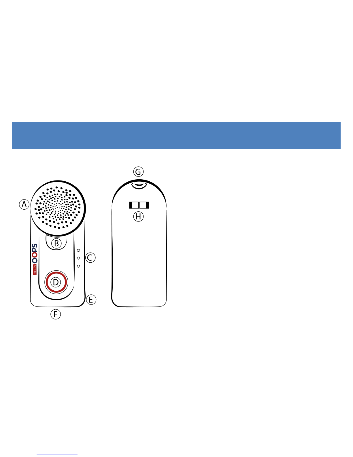
HARDWARE DESCRIPTION
A Loudspeaker
B Pushbutton 2
C LED
D Pushbutton 1
E Microphone
F Micro-USB connector
G Necklace hole
H Clip
Page 9
9
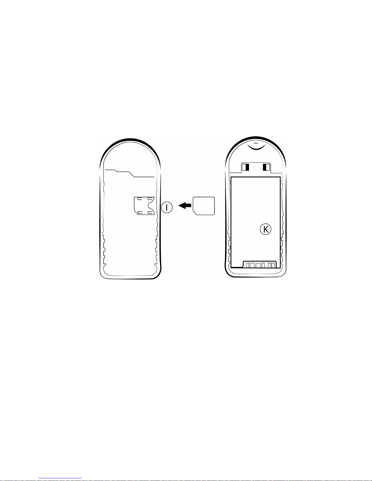
I Micro SIM Card holder
K 3,7V 1150 mAh LiPo battery
Page 10
10
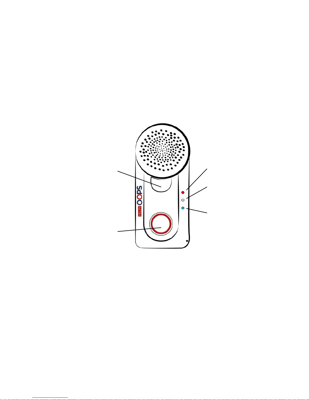
Pushbutton 2
- to send or end a standard
phone call
- to reset an alarm
- to answer an incoming call
- to adjust the conversation
volume
- to visualize the LED status
Pushbutton 1
- to power on HELPY OOPS
- to send an alarm
GSM / ALARM LED
BATTERY / CONVERSATION
LED
GPS LED
Page 11
11
OPERATION
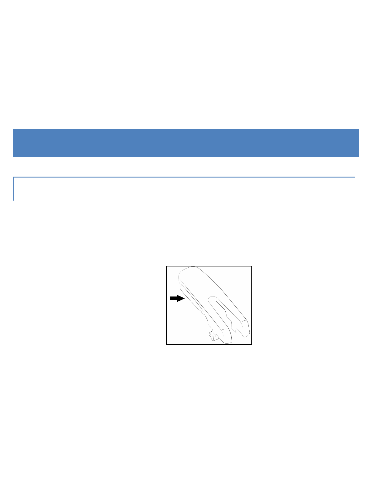
OPENING DEVICE
To open up the Helpy Oops, use the clip coming with the unit (picture
1) by sliding it from the top along the side hole, as shown in the
pictures 2 and 3:
1.
Page 12

12
2. 3.
Page 13

13
INSERTING SIM CARD
Insert the micro SIM card with the contacts facing down.
The PIN code of the SIM card must be removed before inserting.
The SIM card must support the GSM network and a voice & data
contract is highly recommended.
REMOVING BATTERY LABEL
Remove the adhesive label applied to the battery contacts.
Page 14
14
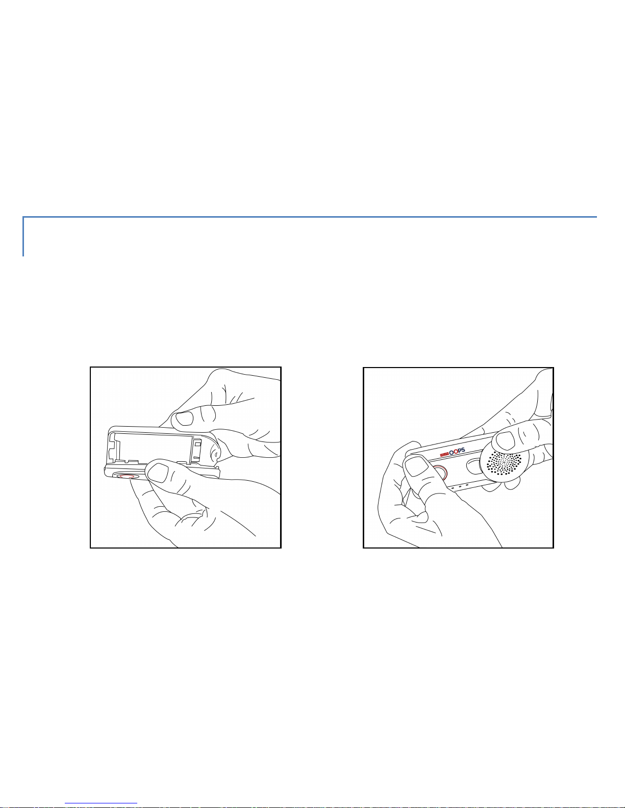
CLOSING DEVICE
Press to close the Helpy Oops until you hear it click , as shown in the
pictures. Once closed, the Helpy Oops automatically switches on.
1. 2.
Page 15

15
CONNECTING ACCESSORIES
SILICON PROTECTION
Insert the Helpy Oops in the silicon cover to protect the device from
shocks and to avoid the opening in case of fall.
NECKLACE
Insert the strap in the dedicated holes and fix it, as shown in the
following pictures:
Page 16

16
1. 2.
3. 4.
Page 17

17
CLIP
Hook the clip to the specific mount on the back of Helpy Oops (see H
at page 8).
To unhook the clip push the two ends one towards the other.
Page 18

18
POWER ON
Keep Pushbutton 1 pressed for 2 seconds.
All the LEDs will light up.
POWER OFF
Keep pressed Pushbutton 1 and Pushbutton 2 simultaneously for 2
seconds.
All the LEDs will light up steady and will switch off.
Page 19

19
LEDS
IDLE STATUS
With full-charge battery, only the white LED blinks slowly.
With low battery, only the red LED blinks slowly.
CHARGING STATUS
While charging, only the red LED is steady lit.
When the battery has been charged, only the white LED is steady lit.
Page 20

20
GSM/BATTERY/GPS STATUS
Push shortly Pushbutton 2 to visualize the GSM signal strength (red
LED), the battery charging level (white LED) and the GPS signal
strength (blue LED).
From 1 to 4 blinks (1: low level, ... , 4: high level).
A continuous blinking of the blue LED means the GSP signal search.
WARNING
To connect the GPS signal coming from
satellites may need to power on Helpy Oops
outside.
Page 21

21
ALARM STATUS OR GENERIC CALL
ALARM
The red LED blinks quickly during all the alarm procedure.
The white LED blinks quickly during the call and it lits up fixly during
the conversation.
GENERIC CALL
The white LED blinks quickly during the call and it lits up fixly during
the conversation.
Page 22

22
OPERATION
EMERGENCY CALL
Helpy Oops, properly programmed, sends a rescue call by pressing
the Pushbutton 1 or after an accidental fall.
WARNING
For proper fall detection, it is recommended
that Helpy Oops is anchored to the body and
secured through the clip coming with the unit.
Page 23

23
Remark
The fall detection systems evaluates, after an impact, the height variation and
the Helpy Oops' rotation comparing to the standard vertical position.
The alarm call is not sent if the person gets up within 15 seconds from the
impact restoring the correct position of Helpy Oops.
Remark
The Pushbutton 1 delay is programmable.
The alarm can be sent out in the following modes:
CALL MODE
Helpy Oops makes voice calls in a sequence to one or more preset
phone numbers until it is answered.
Page 24

24
WARNING
To prevent unsolicited interruption of the
alarm call cycle make sure the voicemail
service is disabled on the preset numbers or,
via pc, set the number of calls that you wish to
be answered.
SMS MODE
Helpy Oops sends an SMS to one or more preset numbers.
The message text also delivers the latest detected GPS position.
Page 25

25
SMS / CALL MODE
Helpy Oops sends an SMS to one or more preset numbers and then
makes voice calls in a sequence until it is answered.
PRE-ALARM SMS / CALL MODE
Helpy Oops sends an SMS to one or more preset numbers, expecting
to receive a callback. If Helpy Oops is not called back within a
programmable timeout, it will start making voice calls in a sequence
until it is answered.
Page 26

26
GENERIC CALL
Helpy Oops makes a standard phone call to a single preset number
upon pressing Pushbutton 2.
The pushbutton delay is programmable.
ALARM RESET OR GENERIC-CALL END
Helpy Oops allows to end a generic call or reset an alarm by pressing
twice Pushbutton 2.
Page 27

27
INCOMING CALLS
Helpy Oops incoming calls can be answered either by pressing
Pushbutton 2 or by automatic answer after a preset number of rings.
CONVERSATION VOLUME ADJUSTMENT
In idle status, Helpy Oops allows to adjust the conversation volume
by pressing twice Pushbutton 2; a beep will be heard repeatedly until
the desired volume level is achieved.
Page 28

28
LOW BATTERY
Helpy Oops can be configured so as to send an SMS notifying low
battery to a predefined phone number.
The battery status can be checked remotely by SMS request.
In idle mode, the low-battery status is signaled by the red LED slowly
blinking and by a prolonged beep (lasting 4 seconds) repeated every
3 minutes.
Page 29

29
PERIODIC TEST
Helpy Oops can be configured so as to send an SMS notifying proper
operation to a predefined phone number.
The periodic test can be forced remotely by SMS request.
ROOM-MONITOR
Helpy Oops allows selected remote callers to go into listening mode
for environmental monitor purposes.
Page 30

30
GPS TRACKING
Upon receiving an SMS request, Helpy Oops sends a return text
message delivering GPS location with map links for smartphone
users.
GEOFENCING
Helpy Oops, properly programmed, sends an SMS, followed by a
voice call if preset, to a stored number. This indicates that the person
wearing the unit has entered or exited a predefined geographic area.
Page 31

31
PARAMETER CONFIGURATION
PARAMETER SETTING VIA PC SOFTWARE
Advanced programming of Helpy Oops can only be performed via the
dedicated Helpy Oops Assistant software.
Helpy Oops Assistant is available as a free download on
www.helpyoops.it.
Page 32

32
PARAMETER SETTING VIA SMS
Helpy Oops can be partially configured remotely via SMS.
SMS configuration can be effected by any mobile phone or other tool
providing SMS-sending capability. A return SMS will be sent by Helpy
Oops delivering confirmation notification.
WARNING
SMS settings effected via Internet might not be
successfully sent if the required text format is
not respected.
Below is the quick list of message texts required to configure
remotely your Helpy Oops.
Page 33

33
CHANGING PASSWORD TO ACCESS
PROGRAMMING MODE
Et.h#old_password#PASS#new_password#new_password#
Factory-default password: 0
New password: max. 7 alphanumeric characters
Example:
To change the factory-default password (0) with a new password (abcd123) ,
send the following SMS:
Et.h#0#PASS#abcd123#abcd123#
Page 34

34
SETTING THE TELEPHONE NUMBERS TO BE
CALLED UPON PRESSING PUSHBUTTON 1
Et.h#password#S#first_telephone_number#second_telephone
_number#……#sixth_ telephone_number#
Example:
Accessing by factory-default password (0), in order to program 2 telephone
numbers (3338888888 and 3330000000) send the following SMS:
Et.h#0#S#3338888888#3330000000#
Remark
Each new SMS automatically removes the previously stored numbers.
Page 35

35
SETTING THE TELEPHONE NUMBER TO BE CALLED
UPON PRESSING PUSHBUTTON 2
Et.h#password#P2#telephone_number#
ACTIVATING NOTIFICATION SMS IN CASE OF LOW
BATTERY
Et.h#password#BATT#telephone_number#
Page 36

36
ACTIVATING DAILY SMS OF SELF-TESTS
Et.h#password#AThhmm#telephone_number#
where hhmm = hours and minutes
Example:
Accessing by factory-default password (0), send the following message text in
order to program the telephone number (3338888888) to be notified the daily
self-test and set the time at 10.15:
Et.h#0#AT1015#3338888888#
Page 37

37
ACTIVATING ROOM-MONITOR FUNCTIONALITY
Et.h#password#RM#telephone_number#
APN SETTINGS
Et.h#password#APN#APN_gsm_provider#
Setting the APN is recommended to reduce the time for locating your Helpy
Oops. To avoid undesidered extra-costs, please verify that your SIM card
provides a voice & data plan. The correct APN for your SIM card must be
requested to your GSM provider.
Page 38

38
DELETING A CONFIGURATION
To delete a single configuration (i.e. disabling a function or deleting a
previously stored telephone number) send the related activation SMS
neglecting the telephone number.
Example:
Accessing by factory-default password (0), send the following message text in
order to disable the room-monitor functionality:
Et.h#0#RM##
DELETING ALL PARAMETERS
Et.h#password#RESET#
Page 39

39
REQUESTING GPS LOCATION
Et.h#password#POS#
REQUESTING BATTERY STATUS
Et.h#password#BATTERY#
REQUESTING DAILY SELF-TEST
Et.h#password#AUTOTEST#
Page 40

40
CHARGING BATTERY
Low battery is indicated:
- in idle status, by the red LED slowly blinking
- by a prolonged beep (lasting 4 seconds) repeated every 3 minutes.
- To charge the battery, use the USB adapter supplied with the unit or
other certified USB adapter.
- To replace the battery, contact your local authorized technical
center.
- Do not expose the battery or the device to heat sources.
Page 41

41
DISPOSAL
This appliance is marked according to the European directive 2002/96/EC on Waste Electrical and
Electronic Equipment (WEEE).
The symbol (above) appears on this product. It indicates that the product should not be disposed of as
unsorted household waste, but by means of separate collection.
Electrical and electronic equipment may contain pollutants having a negative impact on both the
environment and the human health. The WEEE should be therefore returned to the local collection
points, in order to ensure proper treatment, or it should be returned to the reseller upon the purchase
of an equivalent product.
Esse-ti S.r.l. wishes to inform its customers that the unauthorized treatment of WEEE is punished by the
law and harmful to the environment and the human health.
Page 42

42
Page 43

43
Page 44

Esse-ti s.r.l.
Via G. Capodaglio, 9
62019 Recanati (MC) – ITALIA
Tel. +39 071 7506066
Fax +39 071 7506057
www.helpyoops.it
e-mail: support@esse-ti.it
 Loading...