

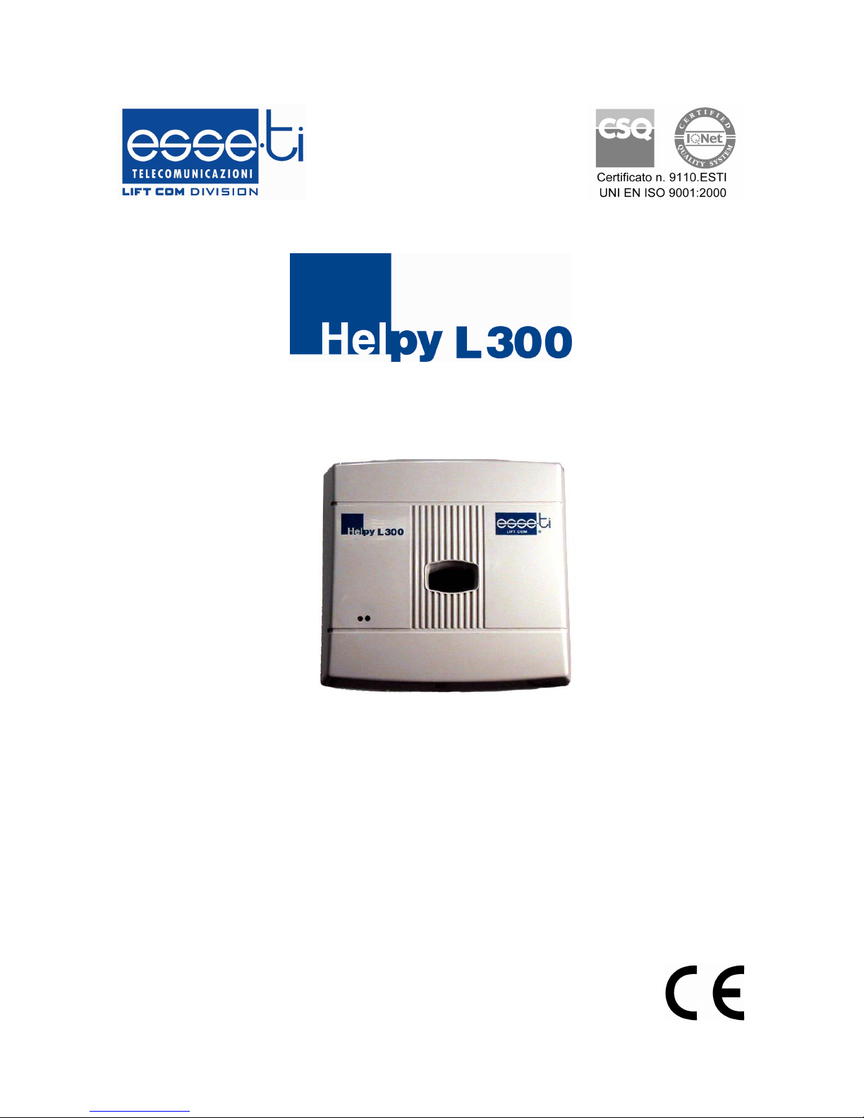
Elevator alarm system
USER’S MANUAL
Installation and use

Thanks for choosing an Esse-ti product
This product has been especially designed to
manage emergency calls generated in elevators. It
has been manufactured with perfect workmanship
using suitable materials for long-lasting
performance.
All Esse-ti products are subjected to extensive
specific testing in our laboratories in order to
provide total guarantee for the User.
The User shall be responsible for defects arising from the use of the product. Esse-ti
shall only be responsible for defects according to and within the limitations set by the
Presidential Decree dated 24/05/1988 no. 224 (fulfilling the EEC directive no. 85/374 on
the harmonization of statutory and administrative regulations of the Member States on
the liability for damages arising from defective products under art. 15 of Law no. 183 of
16 April 1987).
Esse-ti reserves the right to modify the product characteristics at any time
without prior notice.

TABLE OF CONTENTS
EDITING CRITERIA.............................................................................................................5
GENERAL INSTALLATION INSTRUCTIONS ..................................................................7
General Notes.....................................................................................................................7
Warnings ............................................................................................................................7
Making the installation.......................................................................................................7
DESCRIPTION ......................................................................................................................8
Main Functions And Features ............................................................................................8
OPERATION .......................................................................................................................11
Operation in idle state.......................................................................................................11
Alarm calls .......................................................................................................................11
Call cycles ........................................................................................................................................12
Emergency-call alarm ......................................................................................................................13
Technological, remaining SIM credit alarms and Diagnostics .......................................................19
Automatic Test calls.........................................................................................................20
Automatic test ..................................................................................................................................20
Manual test.......................................................................................................................................21
INSTALLATION .................................................................................................................23
Recommendations............................................................................................................................23
Mounting..........................................................................................................................23
Connections......................................................................................................................24
Connecting the telephone line .........................................................................................................25
Other connections ............................................................................................................................27
Quick instructions to check the correct installation..........................................................31
HOW TO USE THE RESET PUSHBUTTON................................................................32
PROGRAMMING................................................................................................................33
Accessing and exiting programming ...............................................................................................33
From the local telephone..................................................................................................................34
From a remote telephone .................................................................................................................35
BASIC PROGRAMMING...............................................................................................36
Programming the type of telephone line..........................................................................................36
Programming the telephone numbers ..............................................................................................37
Programming the clock ....................................................................................................................39
Recording/playing the identification message.................................................................................40
Type of installation ..........................................................................................................................41
Activating the “dead battery” alarm ................................................................................................42
Programming the automatic test data ..............................................................................................42
Programming the protocols identification code ..............................................................................45
Volumes setting ...............................................................................................................................46
Listening to the settings again .........................................................................................................48
Restoring the default settings ...........................................................................................49
ADVANCED PROGRAMMING ....................................................................................51
Changing the installer password ......................................................................................................51
Changing the operator password .....................................................................................................52
Activating the “no power supply” alarm .........................................................................................53
Activating the “diagnostics” alarm..................................................................................................53
Expiring credit alarm .......................................................................................................................54
Activating the auxiliary alarm 1 ......................................................................................................56
Activating the auxiliary alarm 2 / Gong ..........................................................................................56
Emergency call button normally closed/open .................................................................................57

Delay for emergency call buttons ....................................................................................................58
Filter activation ................................................................................................................................58
Codes for alarms’ management .......................................................................................................59
Recording/playing the courtesy message ........................................................................................62
Handsfree connection time upon alarm ...........................................................................................63
Pulse or DTMF dialling ...................................................................................................................63
Call cycles ........................................................................................................................................64
Connection to switchboard or PSTN line ........................................................................................64
Automatic answer ............................................................................................................................65
USE OF OTHER FUNCTIONS ...........................................................................................67
LOCAL USE....................................................................................................................67
Conversation between the local telephone and the car....................................................................67
Conversation between the local telephone and the handsfree selected by the user ........................68
Testing the handsfree terminals .......................................................................................................68
Making an outgoing call from the local telephone..........................................................................69
Opening doors ..................................................................................................................................70
Remote use with HelpyL300 in stand-by mode................................................................70
Conversation with a handsfree terminal selected by the user. ........................................................71
Testing the handsfree terminals .......................................................................................................71
Opening the doors............................................................................................................................72
Remote use while the emergency call alarm is suspended ...............................................72
Handsfree connection and door opening .........................................................................................72
Resetting the emergency call alarm by remote................................................................................72
Ademco Contact ID Protocol ...........................................................................................74
MAINTENANCE.................................................................................................................75
fuse replacement...............................................................................................................75
QUICK GUIDE – PROGRAMMING ..................................................................................76
Basic programming ..........................................................................................................76
Advanced Programming...................................................................................................79
QUICK GUIDE – USE.........................................................................................................81
Local.................................................................................................................................81
Remote use with HelpyL300 in stand-by .........................................................................81
TECHNICAL SPECIFICATIONS .......................................................................................82
Tones ................................................................................................................................................82
Status indicator LED’s .....................................................................................................................82
GSM Signal indicator LED’s (only with GSM200 module)...........................................................83
Power supply....................................................................................................................................83
Signalling system .............................................................................................................................83
Voice messages ................................................................................................................................84
Data transmission / communication.................................................................................................84
Protocols...........................................................................................................................................84
Telephone terminations....................................................................................................................84
Connections......................................................................................................................................84
Inputs/ Outputs.................................................................................................................................84
Safety system ...................................................................................................................................85
Other characteristics.........................................................................................................................85
CE conformity declaration ...............................................................................................85
EDITING CRITERIA 5
EDITING CRITERIA
This paragraph describes the editing criteria followed in this manual for easier
user’s reference.
The following table contains examples of the styles used (left) with their logical
meaning (right).
Example Meaning
CHAPTER
TITLE
Style used for the title of chapters. A new
chapter begins on a new page.
PRIMARY TITLE
Style used for the title of large sections in a
chapter, such as the main titles of the chapter.
Secondary Title
Style used for the title of a specific paragraph
in the primary title.
Tertiary Title
Style used for additional sections in a specific
paragraph
Example
Style used for examples.
Note
Style used for explicatory notes: pay attention!
Warning
Style used to indicate possible risks for
individuals and properties: caution!
Normal text
Style used for normal text.
¾ Operation to be carried out
Style used to indicate the sequence of
operations that must be carried out for
programming or service implementation.
6 EDITING CRITERIA
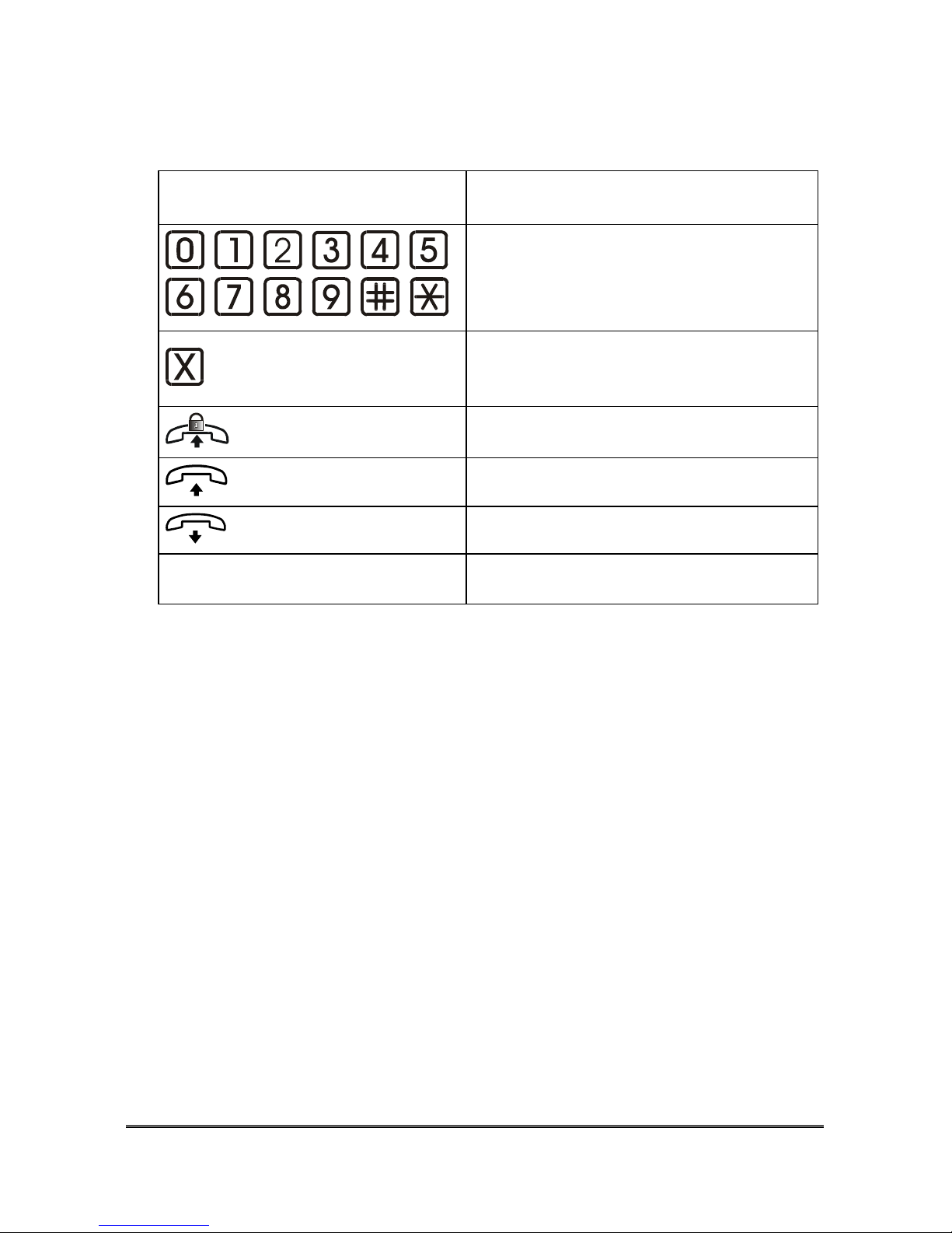
In addition to styles, the manual contains images and symbols showing the
operations to be performed by the User.
Symbol Meaning
, , , , , ,
, , , , , .
Press this button on the telephone keypad.
This symbol indicates a telephone digit. It is
used to indicate the values that must be
entered by the operator during programming.
Pick up the handset. The programming mode
must be active.
Pick up the handset.
Replace the handset.
A [B]
Square brackets indicate optional parts of
codes that can be omitted.

GENERAL INSTALLATION INSTRUCTIONS 7
GENERAL INSTALLATION
INSTRUCTIONS
GENERAL NOTES
Carefully read the notes contained in this section as they provide important
information on safe correct installation, use and maintenance of the product.
• The product must be EXCLUSIVELY used for the purpose it was designed
for. Esse-ti shall not be responsible for damages arising from improper use.
• The product has been designed in compliance with the regulations in force and
must be installed in systems that comply with the provisions of law.
• Before connecting the product to the electric mains, make sure that the line
voltage corresponds to the value indicated on the product label.
• Always disconnect power supply before performing internal or external
operations on the product (cleaning, maintenance, etc.).
• A protection cut-out switch must be installed upstream to interrupt power
supply in case of fault.
• Always refer to an authorized service centre for repair.
• Beware of symbols showing lightening with an arrow inside a triangle, since
they indicate the presence of dangerous voltage.
• For information on how to use the product see "Technical Features”.
• Do not install the product in environments with risk of explosion.
WARNINGS
• Check that the product has been installed correctly.
• Connect protections for power supply and telephone line to the installation.
• For effective protection connect the earth terminal to an earth socket.
• Do not introduce objects, liquids or powders inside the product. Do not use
sprays inside the product.
• When replacing the external battery, arrange for suitable disposal. Do not
dispose of with ordinary waste.
• Packing (plastic bags, foam polystyrene, etc.) must be kept out of the reach of
children because potentially dangerous.
MAKING THE INSTALLATION
The product must be installed by specialized installers.

8 DESCRIPTION
DESCRIPTION
Helpy L300 is an alarm system specifically designed for elevators in
compliance with EN81-28:2004..
Its main function is to make automatic calls to the programmed telephone
numbers if a person is trapped in the elevator and establish a bi-directional
communication between the trapped person and the rescue service. The device
can also make calls to inform about malfunctioning or anomalies of the alarm
system and automatic test calls on a regular basis (in compliance with section
4.2.1 of the EN81:28:2004 standard).
The device is typically installed in the elevator room near the electric control
cabinet of the elevator and can be programmed and used with an ordinary
multi-frequency telephone, defined as “local telephone" in the manual, directly
connected to the device.
MAIN FUNCTIONS AND FEATURES
• It can be connected to the fixed public telephone network (standard
operation mode) or to the GSM line (with the installation of the Esse-ti
GSM200 proprietary module).
• Types of alarm:
- Emergency-call alarm: max. of 3 buttons, of which, typically, one
button for the elevator car and two optional buttons for roof and pit.
Each button can be matched with a handsfree device (Esse-ti
“active” handsfree terminal) for external two-way communication
or with the local telephone situated in the elevator machine room.
Alternatively to standard active handsfree terminals connected to
the three Helpy L300 independent outputs VV1, VV2 or VV3, you
can connect one Esse-ti proprietary “passive” handsfree device in
parallel to each active handsfree terminal. For the roof, for example,
you can use one passive handsfree connected in parallel to the
active handsfree of the car. For information on connection please
refer to the instructions supplied with the passive handsfree device.
- Technological alarms:
- dead battery
- no power supply

DESCRIPTION 9
- 2 inputs for auxiliary alarm
- Alarm from diagnostics
- Alarm from remaining SIM credit (only with GSM200 module)
• Automatic Test Call (EN-81:28 4.2.1).
• 12 telephone numbers that, during programming, can be individually
associated with:
- emergency-call alarm
- technological alarms and diagnostics
- remaining SIM credit alarm
- automatic test call
• 5 types of alarm destination:
- ordinary telephone users
- service center with Ademco contact ID protocol
- service center with Esse-ti protocol (HeCall).
- service center wotking under CLI mode
- SMS (only with GSM200, except for emergency-call alarms)
In case of standard telephone users, the person who answers the calls must
enter suitable programmable codes to manage the alarm. In case of service
centers with automatic protocols and software, please refer to the
corresponding documentation. In case of SMS , a text message is sent out
to the programmed telephone number warning about the alarm event.
Each type of alarm can be associated with multiple telephone numbers
(which will be called in a sequence), also with different destination types.
• 1 filter input for an external sensor in order to avoid emergency call alarms
when the car is at the floor and all doors are open or the car is moving and
the doors will open at the next floor. The filter has no effect on buttons 2
(pit) and 3 (roof), if any.
• 60 voice messages totalling 4 minutes’ recording:
- Customisable elevator identification message (max. 22 seconds). It
must be recorded during the first installation.
- Courtesy message broadcast in the car after the emergency call by
the trapped person (max. 22 seconds). The device is provided with a
pre-recorded courtesy message. Alternatively, you can record your
own courtesy message.
- Pre-recorded messages that identify the type of alarm (not
customizable).

10 DESCRIPTION
• Management of GIVEN ALARM INDICATOR LIGHT and RECEIVED
ALARM INDICATOR LIGHT.
• 2 Relays for door-openers.
• Local Programming through the local telephone. Remote programming via
analog telephone or Esse-ti programming software.
The device has three priority levels for the events.
• High priority: emergency call buttons
• Medium priority: technological alarms, remaining SIM credit alarm.
• Low priority: automatic test, diagnostics.
Higher priority alarms abort lower priority alarms (thus the emergency call
alarm aborts all the others). When the higher priority alarm ends, the system
resumes the aborted alarm procedure.

OPERATION 11
OPERATION
OPERATION IN IDLE STATE
In idle state the device (if these checks are enabled):
• Checks the battery status every 2 hours (“dead battery” technological
alarm);
• Checks the operation of the alarm system (diagnostics) every day at
programmable time.
If the one of these checks shows a malfunction (dead battery or malfunction
detected by the diagnostics procedure) the device starts the alarm procedure
described in “Alarm calls”.
• Makes a periodical automatic test call in compliance with EN 81-28:2004
with programmable frequency.
At the time set for the periodic automatic test call the device will call the
programmed number (or numbers) according to the procedure illustrated in
section “Automatic Test calls ”.
ALARM CALLS
WARNING
If the alarm procedure is activated by mistake and
you have programmed a wrong number, and IT IS
IMPOSSIBLE TO INTERRUPT THE ALARM
PROCEDURE REMOTELY, please follow the
procedure below: lift the handset of the local
telephone and enter * <Key word> # within 20
seconds (by default: ). The alarm ends
and the device returns to the idle state.

12 OPERATION
This section continues with a description of the alarm management mode by
standard telephone users. For information about alarm management with
automatic protocols (Esse-ti or Ademco Contact ID) please refer to the
corresponding documentation. The following codes (“Acknowledgement”,
“Handsfree”, “Exclusion” and “End”) are factory-set codes. In case of reprogramming, you must use the new codes. The “Exclusion” and “End” codes
are also used in the Ademco Contact ID protocol.
Call cycles
Upon an alarm or during the automatic test, the device generates a sequence of
calls to the numbers programmed and associated with the event. The device
makes two consecutive calls to each number. Each call lasts up to 1 minute.
After calling the last number, the device starts a new cycle of calls, supposed
no one answered and gave HelpyL300 the proper codes, starting from the first
number.
The number of call cycles can be programmed from 1 to 10 for technological
alarms, diagnostics, remaining credit and automatic test call (by default it is set
at 5). In order for the calls to be held valid and accepted by Helpy L300, the
called party must not be found busy.
A special feature of the technological alarms, diagnostics and the automatic test
call is the "CLI" – mode. By routing the calls associated with different alarms
to different telephone lines, the call center manages to discriminate which type
of alarm has been received thanks to the information contained in the CLI
(caller line identification). In this way, it is not required to establish a
connection in order to determine the event, you simply need to be sure that at
least one call has been forwarded to a free telephone number. By setting a call
center working under “CLI” mode as the destination of an alarm call, the Helpy
L300 will carry out as many call cycles to the programmed numbers until it
succeeds to reach a free telephone number. At this point, the calls will end
without any further need to be answered.
As far as the emergency-call alarms are concerned, the number of call cycles is
unlimited.

OPERATION 13
Emergency-call alarm
This is the main function of the device.
When the emergency-call pushbutton is pressed, the device makes a sequence
of calls to the programmed numbers associated with the specific type of alarm.
Simultaneously:
• a courtesy message is played back in alternation with pauses and tones
in the place where the alarm is generated (e.g. elevator car)
• the “given alarm” indicator light turns on.
Note: the alarm for button 1 (installed in the car) is subject to the
filter input status, if enabled.
WARNING:
The filter input must be disabled during
maintenance operations of the elevator system.
How to answer an emergency call and reset
immediately the alarm
Please refer to the diagram on page 17.
¾ After answering the call, a series of tones will be heard.
¾ Dial
(“Acknowledge” code) or wait a few seconds. You listen to the
alarm identification message (“Emergency call”) followed by the elevator
identification message (which must be recorded during installation).
Note: you can listen to the messages again at any time by re-
dialling
(“Acknowledge” code).
¾ After 30 seconds an automatic connection with the handsfree is
established and you can talk to the person who called for help. You can
also establish the handsfree connection immediately, while listening to
the ID message, by dialling
(“Handsfree activation” code).
The duration of the handsfree connection is limited (programmable, 2 minutes
by default). The conversation time can be extended by entering any digit

14 OPERATION
different from (“Exclusion”), (“End”) and (“Acknowledge”) at
warning tone. Conversation time can be extended an unlimited number of
times.
¾ Dial (“Exclusion” code) to suspend the alarm. The “Received alarm”
indicator light turns on.
¾ Dial
(“End” code).
The alarm is reset and the device goes in stand-by mode.
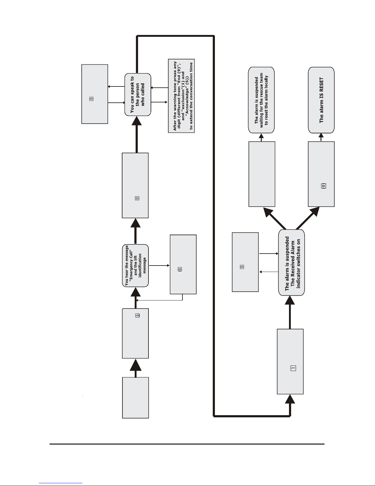
How to answer an emergency call and suspend the
alarm: the alarm will be terminated by the rescue team
locally.
Please refer to the diagram on page 17.
¾ Answer the alarm call. You hear a series of tones.
¾ Dial
(“Aknowledge” code) or wait. You listen to the alarm
identification message (“Emergency call”) followed by the elevator
identification message (which must be recorded during installation).
Note: you can listen to the messages at any moment by dialling
(“Acknowledge” code).
¾ After 30 seconds an automatic connection to the handsfree is
established and you can talk to the person who called for help. You can
also establish the handsfree connection immediately, while listening to
the messages, by dialling
(“Handsfree activation” code).
The duration of the handsfree connection is limited (programmable, 3
minutes by default). The conversation time can be extended by entering any
digit different from
(“Exclusion”), (“End”) and (“Aknowledge”)
at warning tone.
¾ Dial (“Exclusion” code) to suspend the alarm. The “Received alarm”
indicator light turns on. The alarm is suspended, waiting for the rescue
team to terminate it.
¾ Hang up. If the alarm is not reset within 60 minutes it automatically
restarts. While the alarm is suspended, by pressing any emergency
button another alarm cycle begins.
OPERATION 15
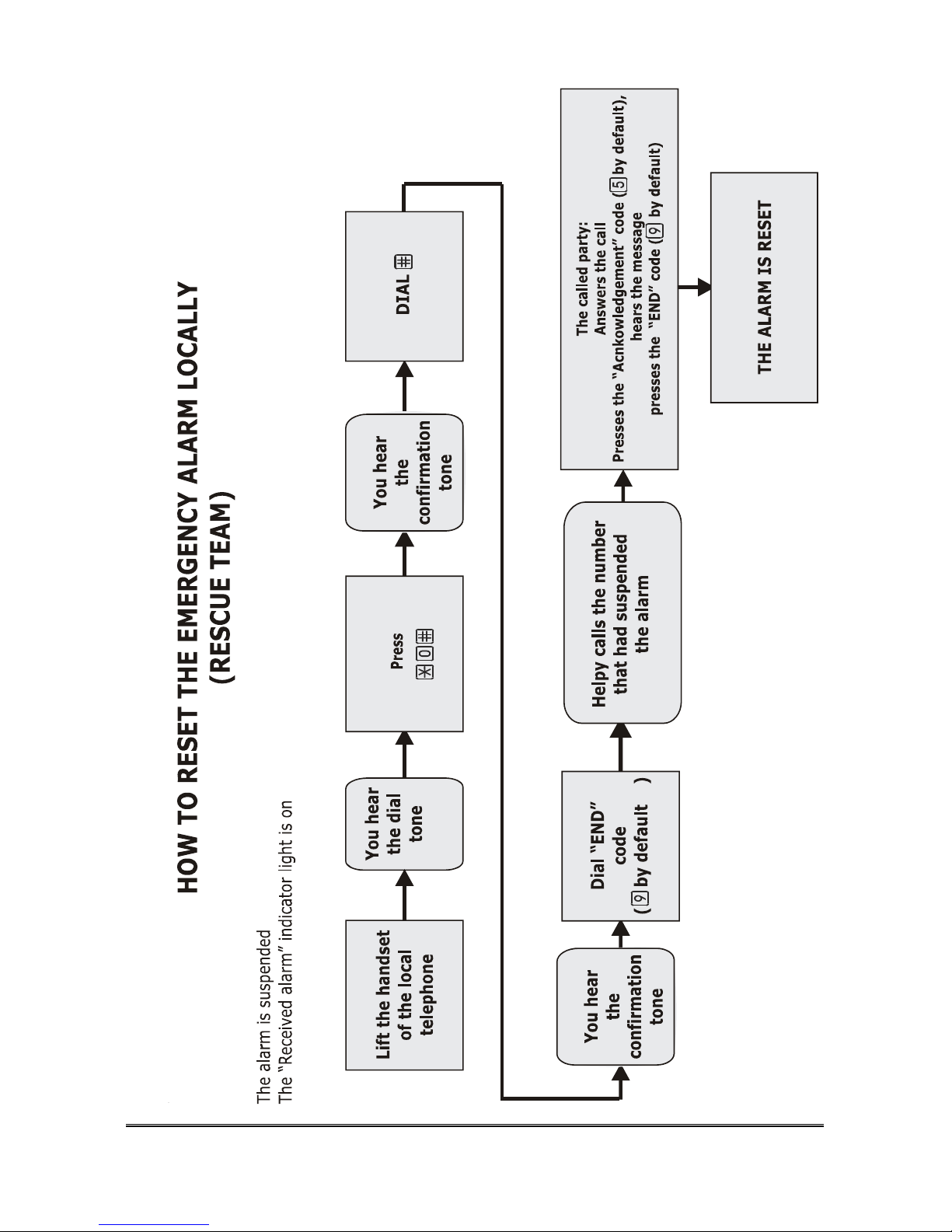
Local reset (rescue team)
Please refer to the diagram on page 18.
The alarm is suspended, the “Received alarm” indicator light in the car is on.
¾ Lift the handset of the local telephone; you hear the dialling tone.
¾ Dial
<password> (by default: ).
¾ Dial
. You hear the confirmation tone.
¾ Dial
(“End” code). You hear the confirmation tone.
HelpyL300 automatically generates a call to the number that suspended the
alarm in order to notify that the alarm has been reset. The called user must:
¾ Answer the call (he hears a series of tones).
¾ Dial
(“Acknowledge” code) or wait.
He listens to the “Alarm end” message followed by the elevator identification
message.
¾ Dial (“End” code). The line is cleared.
The following operations can be carried out from remote while
the alarm is suspended:
While the alarm is suspended it is also possible to call HelpyL300 and:
• Establish a handsfree connection with the person who called for help
and with the other handsfree devices;
• Open the doors;
• Reset the alarm by remote.
¾ Call HelpyL300 and wait for the answer.
As soon as HelpyL300 answers the call a handsfree connection is automatically
established with the person who called for help.
¾ Dial <password> (by default: ).
1. In order to establish a connection with any of the handsfree devices
dial:
Handsfree 1;
Handsfree 2;

16 OPERATION
Handsfree 3;
Disconnect all;
The activation of Handsfree 2 and 3 depends on the type of installation
programmed.
2. In order to open the doors dial:
Open door 1;
Open door 2.
3. In order to reset the alarm by remote:
¾ Dial . You hear the confirmation tone.
¾ Dial
(“End” code). The line is cleared and the alarm is reset.
OPERATION 17
HOW
TO
MANAGE
THE HELP C
A
LL
Answer the call
You hear a
series of tones
Press the “Acknowledge”
code ( by default)
to listen to the message
again
Press the
“ACNOWLEDGE”
code (by default )
or await
Dial the “Exclusion”
code ( by default)
Hang up
Press the
“HANDSFREE” code
( by default)
or await
Press the “Acknowledge”
code ( by default)
to listen to the message
again
Press the “Acknowledge”
code ( by default)
to listen to the message
again
Press the “END” code
( by default)
18 OPERATION

OPERATION 19
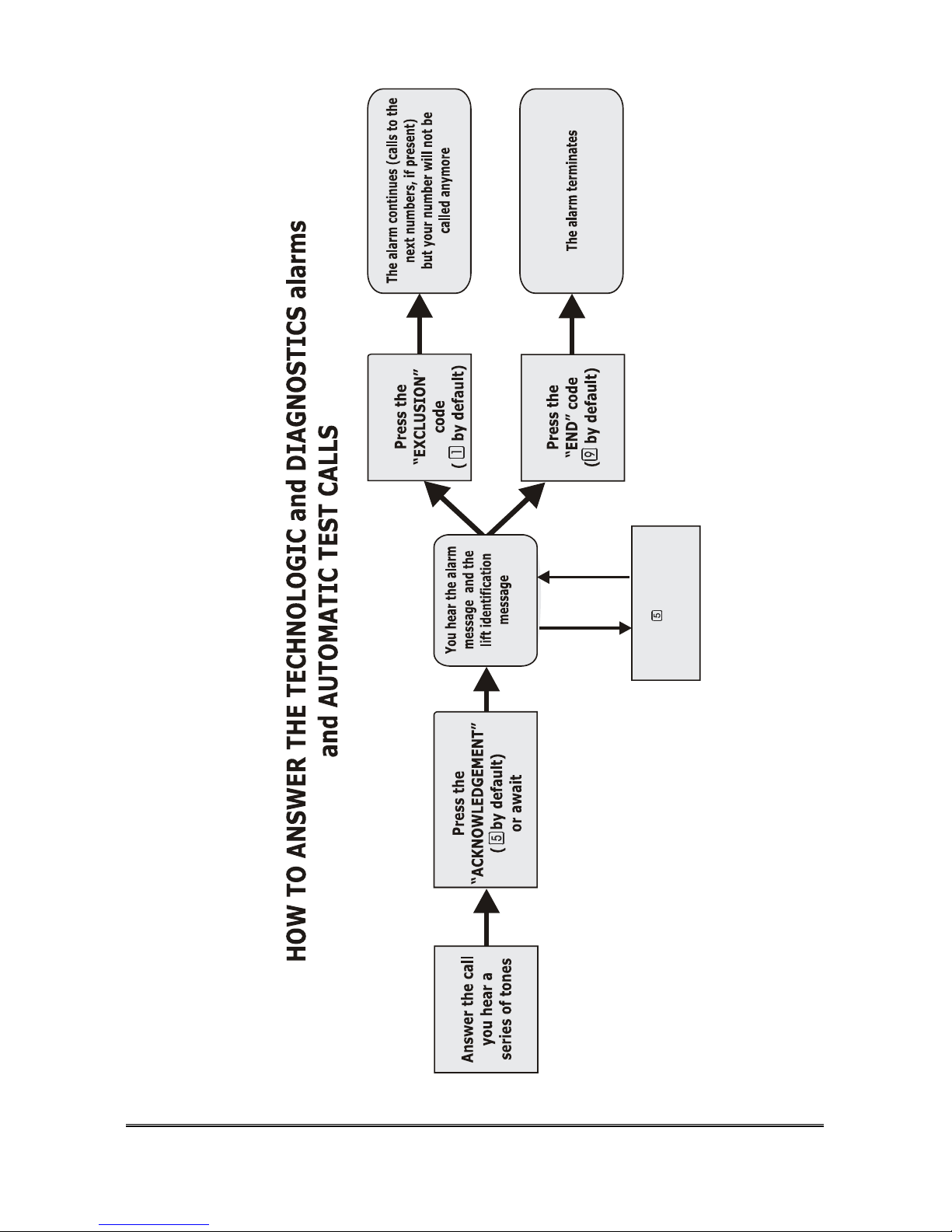
Technological, remaining SIM credit alarms and
Diagnostics
In case of a technological alarms:
• no power supply
• dead battery
• auxiliary alarm
the device calls the numbers associated to this type of events.
The diagnostic procedure, if enabled, is performed every day at the time
programmed for the automatic test call (default setting: 04:00 a.m.). The
following checks are made:
• The recorded messages
• The correct operation of the tone decoder
• The correct operation of handsfree devices
When malfunction is detected in the diagnostics procedure the device starts a
cycle of calls to the programmed numbers associated with this type of event.
If the remaining SIM credit alarm is enabled (only in connection with
GSM200), the amount of the remaining SIM credit will be acquired at the end
of each outgoing call. Such an amount will be compared with the pre-set
minimum value, and in case it should be lower the device will start a cycle of
calls to the programmed telephone numbers associated with this type of event.
Please refer to the diagram on page 22.
¾ Answer the alarm call. You hear a series of tones.
¾ Dial
(“Acknowledge” code) or wait.
¾ You listen to the alarm identification message (“No power supply” or “Dead
battery”, or” Auxiliary” or “Diagnostics” or “Remaining SIM credit) followed
by the elevator identification message.
Now:
¾ In order to exclude yourself from the alarm procedure dial “Exclusion”
code): the procedure continues, but the number is not called again in the
next cycles.
OR

20 OPERATION
¾ In order to interrupt the alarm dial (“End” code). No other telephone
number will be called and the alarm is terminated.
Note: the above-mentioned procedure is not applicable under the
CLI-mode.
AUTOMATIC TEST CALLS
Automatic test
According to the norms on elevator alarm systems (EN 81-28:2004) the system
makes periodical calls to indicate normal operation (for the activation of this
feature please see “Programming the automatic test data” on page 42). The
device makes calls to the numbers associated with the automatic test.
Please refer to the diagram on page 22.
¾ Answer the alarm call. You hear a series of tones.
¾ Dial
(“Acknowledge” code) or wait.
¾ You listen to the “Automatic test” message followed by the elevator
identification message.
Now:
¾ In order to exclude yourself from the procedure dial “Exclusion” code):
the procedure continues, but the number is not called again in the next
cycles.
OR
¾ In order to interrupt the calls dial (“End” code). No other telephone
number will be called and the procedure is terminated.
NOTE: the above-mentioned procedure is not applicable under the
CLI-mode.

OPERATION 21
WARNING
If the automatic test call cannot be ended from
remote (for example because the telephone number
is wrong), you can interrupt the procedure as
shown below:
Lift the handset of the local telephone and enter *
<Key word> # within 20 seconds
(by default: ).
Dial * <key word> # again
Dial 340
Dial *< key word ># again
Manual test
In compliance with norms and regulations, a manual test of the installation
must be performed periodically by pressing the emergency call button and
establishing a handsfree conversation.
The device considers the test as an ordinary emergency call.
22 OPERATION
Press the “Acknowledge”
code ( by default)
to listen to the message
again
INSTALLATION 23
INSTALLATION
Recommendations
• Keep the cables away from high voltage cables or other cables that may
produce electromagnetic interference.
• Do not lay telephone cables near the 230V mains.
• To protect the telephone line, connect the terminal shown with
in the
connection diagram to the earth terminal.
MOUNTING
The device is normally installed in the elevator room near the elevator electrical
board.
¾ Drill two holes on the wall 6 cm apart and fix the bracket with the screws
¾ Place the device on the bracket and make it slide.
¾ Open the device by loosening the screw.

24 INSTALLATION
CONNECTIONS
A RJ11 Connector for local telephone
B LEDs indicating device operation and GSM signal strength
C Jumpers JP11 and JP12 for:
Telephone Line / GSM200 module selection
D RJ45 connector for GSM200 module
E Programmer strip
F Power supply terminals 230V~
G Serial plug for connection to elevator CPU

INSTALLATION 25
H Battery protection fuse (1A)
R Reset pushbutton
I Terminal blocks:
Earth for external line
LTI Telephone line input
LTO Telephone line output
TEL Local Telephone
VV1+ Output Handsfree 1
VV1- Common Handsfree 1
VV2+ Output Handsfree 2
VV2- Common Handsfree 2
VV3+ Output Handsfree 3
IN3 Auxiliary alarm input 2 or Gong
AL1 Alarm input 1
AL2 Alarm input 2
AL3 Alarm input 3
AR Received alarm indicator light
+12 Output 12Vdc (max. 100mA)
C Common terminal for inputs IN1, IN2, IN3
IN1 Alarm filter input
IN2 Auxiliary alarm input 1
RL1 Relay contact 1
RL2 Relay contact 2
BATT Battery
AI Given alarm indicator light
UA Vacant
LD Vacant
Connecting the telephone line
The device allows the connection of a PSTN line or GSM line by means of the
GSM200 module (see “Programming the type of telephone line” on page 36).
PSTN Line connection:
• Connect the ground terminal (indicated with ) to increase telephone line
protection.

26 INSTALLATION
• Make sure that Jumpers JP11 e JP12 are set as in position 1-2 (default
setting).
• Connect the telephone line to terminal LTI.
GSM200 Module Connection:
• Please see also the GSM200 User Manual.
• Make sure that Jumpers JP11 e JP12 are set as in position 2-3 (towards
the RJ45 connector)
• Connect the cable supplied with the GSM module to connector RJ45 (D in
the figure 24).
Note: when connecting the GSM200 Module, please make sure that
a 2A/h-12V battery is connected with Helpy L300.

INSTALLATION 27
Other connections

28 INSTALLATION
It is recommended to remove the terminals, make the connections and replace
the terminals in the correct position.
¾ Connect the local telephone (for programming and managing HelpyL300)
to the TEL terminals (irrespective of the polarity) or directly to the RJ11
connector (see “A” in the picture at page 24).
¾ Connect the handsfree terminals and the emergency buttons:
You can install up to 3 independent handsfree terminals:
¾ Handsfree 1 in the CAR: VV1+,VV1-
¾ Handsfree 2 on the ROOF: VV2+,VV2-
¾ Handsfree 3 in the PIT: VV3+,VV2-
Beware of terminal polarity.
The total number of active hands-free terminals must correspond to the type of
installation programmed in the device (please see “Type of installation” at page
41); the association between alarm buttons and handsfree terminals is made
according to the type of installation, as follows:
Type of installation 1:
HANDSFREE 1 (VV1+, VV1-)
Button 1 corresponds to HANDSFREE 1;
also buttons 2 and 3 (optional)
correspond to HANDSFREE 1
BUTTON 1
BUTTON 2
(OPTIONAL)
BUTTON 3
(OPTIONAL)
VV1
Type of installation 2:
HANDSFREE 1 (VV1+, VV1-);
HANDSFREE 2 (VV2+,VV2-).
Buttons 1 e 3 (3 is optional) correspond
to HANDSFREE 1, button 2 corresponds
to HANDSFREE 2..
VV1
V
V2
BUTTON 1 BUTTON 2
BUTTON 3
(OPTIONAL)
Type of installation 3:
HANDSFREE 1 (VV1+, VV1-);
HANDSFREE 2 (VV2+,VV2-).
HANDSFREE 3 (VV3+,VV2-).
Button 1 corresponds to HANDSFREE 1,
button 2 corresponds to HANDFREE 2,
button 3 corresponds to HANDSFREE 3.
VV1
VV2V
V3
BUTTON 1 BUTTON 2 BUTTON 3

INSTALLATION 29
The type of installation refers to the number of active handsfree connected, and
not to the passive handsfree connected in parallel, if any.
Note: if the programmed type of installation is not correct (for
example you connect 2 handsfree, and you program type of
installation 1), some of the handsfree will not be active
(handsfree 2 is not active in the example).
Note: the VV terminals must be connected subsequently: do not
connect one handsfree to VV1+,VV1- and the next one to
VV3+, VV2- by leaving VV2+,VV2- empty.
Note: outputs VV1- and VV2- are connected together and can be
used as negative pole up to max. 100mA current.
¾ Connect the “Given alarm” indicator light (YELLOW). It switches on after
pressing the emergency button to indicate the beginning of the alarm
procedure and stays steady light until the end. The indicator light must be a
LED light at 12V, max. 40mA.
¾ Connect the “Received alarm” indicator light (GREEN). It must be 12V,
max. 40mA.
¾ Connect the filter input to IN1.
¾ Connect the “Auxiliary Alarm 1” (if any) to IN2 and the “Auxiliary Alarm 2 /
GONG” to terminal IN3.
IN1, IN2 and IN3 cab be closet in 2 different ways::
• Common terminal (C) connected to the pole of a separate device,
and inputs set at -12V with respect to the Common terminal (when
activated).
OR:
• Common terminal (C) connected to the pole of a separate device,
and inputs set at +12V with respect to the Common terminal (when
activated).
The outputs labelled as +12 and BATT- on the Helpy l300’s block terminals
may be exploited.
¾ Connect , if required, a telephone to the LTO terminals. This telephone is
connected downstream of HelpyL300 and can share the same telephone
line used by HelpyL300 (in case of connection to the fixed telephone line).
¾ Connect, if required, the door openers to relays RL1 and RL2.

30 INSTALLATION
It is also possible to connect a siren and a LED for the emergency call button
according to the following diagram:
A +12V
B AL1 or AL2 or AL3
C VV1- or VV2-
D ALARM SIREN 8-12V max 100mA
E EMERGENCY BUTTON LED
F EMERGENCY BUTTON
Note: the LED is connected in series to the emergency call button
and must have no resistance in series.
¾ Connect the power supply cable:
• Remove the small cover and connect the cable to terminals F shown in the
picture at page 24
• Place the small cover back
• Place the Helpy L300 case back
• Connect the other end of the cable to the 230V~ mains.
¾ Upon switching on, check that the device status LED LD2 (B in the picture
at page 24) stays steady on for about 5 seconds and then starts flashing.
(see paragraph “Status indicator LED’s” on page 82).
Note: in case of GSM200 Module, if the LED “LD2” stays steady
on for more than 2 minutes, please check that the GSM200
Module is properly connected with the HelpyL300.
Note: in case of GSM200 Module , The GSM signal level indicated
by led “LD1” is measured every 10 seconds (see par. “GSM
Signal indicator LED’s (only with GSM200 module)” at page
83).

INSTALLATION 31
Note: the GSM signal strength can also be checked by means of the
associated LED placed on GSM200 module.
¾ Connect the battery (2Ah 12V), paying attention to terminal polarity. In
case of error the battery protection fuse is interrupted.
¾ Disconnect the device from the mains to check the battery operation and
reconnect the device to the mains.
QUICK INSTRUCTIONS TO CHECK THE CORRECT
INSTALLATION
1. PROGRAMMING
• Program the telephone line (PSTN or GSM, by means of the
proprietary GSM200 module): dial
from the local
telephone. You will hear 3 short tones. Dial
for PSTN line
or
for GSM line.
• Program a telephone number for the emergency call: lift the handset
of the local telephone and dial:
<telephone
number>
.
• Record the identification message: (max 22 seconds), which must
contain information about the elevator’s location: dial
and
record the message.
• To listen to the message again : dial
.
• Make an outgoing call in order to check the telephone line: lift the
handset of the local telephone , press
and dial a telephone number.
2. CHECKING THE ALARM PROCEDURE
Press emergency button 1 for more than 2 seconds (factory default setting). The
alarm must start.
32
WARNING
If the alarm procedure is activated by mistake and
you have not programmed the telephone number or
you have programmed a wrong number, and IT IS
IMPOSSIBLE TO INTERRUPT THE ALARM
PROCEDURE FROM REMOTE, please follow the
procedure below: Lift the handset of the local
telephone and enter * <Key word> # within 20
seconds (by default: ). The alarm ends
and the device returns to the idle state.
3. ANSWERING THE ALARM AND RESETTING IT
From the called number answer the call and:
¾ Dial . You will hear the identification message you recorded.
¾ Dial
. You will go into handsfree mode.
¾ Dial
. After about 2 seconds dial .
Note: in case the handsfree termianl’s volumes are not adequately
set, refer to paragraph “Volume setting” at page 46.
HOW TO USE THE RESET PUSHBUTTON
Reset pushbutton (R in picture at page 24):
• Pressing shortly
Allows to interrupt an alarm call.
By pressing shortly you get the same result as lifting the handset of the local
telephone and entering : * <Password> #.
• Pressing longer (15 seconds)
Allows to reset the device.
By pressing longer, Helpy L300 will be re-started with no need to
disconnect the mains cable or the battery.
The reset operation does not alert the previously set parameters.

PROGRAMMING 33
PROGRAMMING
The system can be programmed:
• Locally by means of a DTMF telephone connected to TEL
• Remotely by making a call to the device with a multifrequency telephone
or with the Esse-ti remote programmer and management software. The
Automatic Answer function must be active. The function is active by
default.
It is recommended to use the first option to install the device and check the
correct operation. The remote programmer and management and control
software should be used to programme the device and check the settings. In this
manual reference is made to the local programming mode with DTMF
telephone (also valid in case of remote programming mode). For information
on the remote programming mode see the remote programmer manual.
Note: the default value is shown in bold.
Nota: it is possible to listen again to the programmed settings either
locally or remotely by means of a standard telephone. (see
paragrapf “Listening to the settings again” at page 48).
Accessing and exiting programming
In order to programme the device it is necessary to enter (either locally or
remotely) the programming mode. In addition to the INSTALLER password,
the OPERATOR password is used to perform a reduced number of
programming operations In this manual the password that must be entered is
indicated with 9.
To check whether you are in the programming mode, lift the handset of the
local telephone:
- if you hear the DIALING TONE (1 long tone followed by 1 short
tone, see par. “Tones” at page 82), the device is in programming
mode and you can enter the desired programming codes;
- if you are automatically connected to handsfree 1, the programming
mode has not been entered.

34 PROGRAMMING
Note: if the INSTALLER and the OPERATOR password are the
same (as in the default setting) the device reads the password
as the INSTALLER password.
From the local telephone
ACCESS TO PROGRAMMING
¾ Lift the local telephone handset. The telephone is automatically connected
to handsfree 1.
¾ Dial
<INSTALLER OR OPERATOR PASSWORD> (by default:
).
¾ You will hear the dialling tone (one longer tone followed by a shorter
tone).
It is now possible, also without hanging up, insert the programming codes. It is
not necessary to hang up between a code and another or to insert the password
again (please refer to sections “Basic programming” and “Advanced
programming”).
If you hang up, when lifting the handset again you receive the dialling tone and
it is not necessary to insert the password again to go on with programming.
If a programmed code is correct you receive the confirmation tone (3 short
tones), while if it is wrong you receive the error tone (longer continous tones);
in this case you need to hang up to continue.
EXITING THE PROGRAMMING MODE
In order to activate the settings made you must exit the programming mode.
The same procedure will be used as for entering programming:
¾ Lift the local telephone handset. You hear the dialling tone.
¾ Dial
<INSTALLER OR OPERATOR PASSWORD> (by default:
).
¾ The telephone is automatically connected to handsfree 1.
Note: the programming mode is automatically exited after 30
minutes.

PROGRAMMING 35
From a remote telephone
The Automatic Answer function must be active. The function is active by
default.
ACCESS TO PROGRAMMING
¾ Call HelpyL300. It automatically answers the call (after the programmed
rings; 1 ring by factory default)) and you will listen to the elevator
identification message (recorded during installation), followed by the
dialling tone.
¾ Dial, within 1 minute,
<INSTALLER OR OPERATOR PASSWORD>
(by default:
).
¾ Programme the device.
If the entered code is correct you receive the confirmation tone (3 short tones),
whilst if it is incorrect you receive the error tone (longer continous tones); in
this case you do not need to hang up to continue. The device generates a
warning tone before the maximum conversation time after the automatic
answer has elapsed (see section “Automatic Answer”). Press any key within 10
seconds to reset the maximum conversation time.
EXITING THE PROGRAMMING MODE
Simply hang up to exit the programming mode.

36 PROGRAMMING
BASIC PROGRAMMING
• Select the type of telephone line (PSTN line or GSM line bymeans of
GSM200 module)
• Date and time
• Telephone numbers, in association with the type of alarm and recipient
• Dead battery alarm activation
• Automatic test activation
• Identification message recording
• Type of installation if handsfree terminals are connected to VV2 or
VV3
• Protocols identification code (for use with Call Centers with Ademco
Contact ID or Esse-ti protocols). The device Id number must be
generated by the Call center itself.
• Volume setting with reference to handsfree terminals and messages.
Programming the type of telephone line
Installe
r
Operato
r
9 9
It allows to programme the type of external line:
• PSTN line
• GSM200 Module.
WARNING
This programming must always be done at
installation.
WARNING
Please check that jumpers JP11 and JP12 are in
placed in the correct position (see “Connecting the
telephone line” on page 25)

PROGRAMMING 37
(type)
¾ Lift the handset.
¾ Press 66.
¾ Enter the type of external line:
0 Telephone line (PSTN);
1 GSM 200 module
Note: the use of rechargeable SIM cards is not recommended to
avoid problems when credit is over.
Programming the telephone numbers
Installe
r
Operato
r
9
You can programme up to 12 telephone numbers. Each number may be
associated with any of the following events:
• Emergency-call alarm
• Technological alarms and diagnostics
• Automatic test call
• Remaining SIM credit alarm
and it may correspond to one of the following receivers:
• Standard telephone user
• Call Center working under the Esse-ti protocol (HeCall software)
• Call Center working under the Ademco ContactID protocol
• Call Center working under CLI mode
• SMS (only by means of the GSM200 module , except for emergency-
call alarms)
In order to program the telephone numbers, follow the procedure below:
(POSITION) (SOURCE) (RECEIVER)
… (telephone number with max 20 digits) [ ]
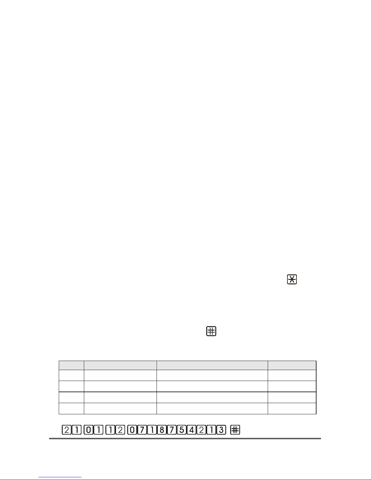
38 PROGRAMMING
¾ Lift the handset.
¾ Press 21.
¾ Enter the position of the telephone number within the table of 12 available
numbers, from 01 to 12.
¾ Enter the type of source, that is to say the event associated with the
number:
1 Emergency call button;
2 Technological alarm and diagnostics alarm;
3 Automatic test alarm
4 Vacant;
5 Exhausting SIM credit alarm.
¾ Enter the figure related to the type of RECEIVER , corresponding to the
specific telephone number:
1 Call Center working under Ademco Contact ID protocol;
2 standard telephone user (manual management of the alarm call);
3 Call Center working under Esse-ti protocol (He Call software);
4 Call Center working under CLI mode;
5 SMS.
¾ Enter the telephone number (max. 20 digits).
¾ Press #.
Note: to enter one or more 2-sec pauses during dialling press
once or repeatedly.
To enter more telephone numbers repeat the assigned code; numbers are called
according to the introduction position.
To delete a telephone number enter directly
after the RECEIVER.
Example:
POS. SOURCE RECEIVER NUMBER
01 EMERGENCY CALL=1 STANDARD TEL USER = 2 0718754213
02 EMERGENCY CALL=1 CALL CENTER ESSE-TI = 3 071986532
03 TECHN. ALARM. = 2 CALL CENTER ADEMCO = 1 071863265
04 EXPIRING CREDIT.= 5 SMS = 5 3331234567
Dial:
for the first number
PROGRAMMING 39
for the second number
for the third number
for the fourth number
WARNING
The receiver can be set as an SMS destination only
when the GSM200 module is connected and the
event is not an emergency-call alarm.
Programming the clock
Installe
r
Operato
r
9
The system is provided with an internal clock. You must programme the date
first and then the time. Besides, if you programme the date you must always
programme the time, too.
Note: the internal clock is provided with a specific battery therefore
it works even if the Helpy L300 is not fed.
DATE
(wd) (dd) (mm) (yy)
¾ Lift the handset.
¾ Press 36.
¾ Enter a number for the weekday:
0 = SUNDAY
1 = MONDAY
2 = TUESDAY’
3 = WEDNESDAY
4 = THURSDAY
5 = FRIDAY
6 = SATURDAY
¾ Enter the date (day month year – two digits).

40 PROGRAMMING
Example: Tuesday Dec 14, 2004 dial:
.
TIME
(hhmm)
¾ Lift the handset.
¾ Press 35.
¾ Enter hour and minutes (from 00:00 to 23:59).
Example: For 14:50 dial:
Note: The system automatically switches from legal to solar time
and vice versa.
Recording/playing the identification message
The elevator’s identification message must be recorded during installation. This
message identifies the elevator during alarm procedures and must contain
information about the elevator’s location.
RECORDING THE MESSAGE
Installe
r
Operato
r
9
(beep) (recording)(beep)
¾ Lift the handset.
¾ Press 7101.
¾ Record the message (22 seconds) after the beep.
¾ At the end of the message, hang up.
Note: it is not compulsory to use all available seconds for correct
recording.

PROGRAMMING 41
Note: A beep indicates that the recording time has elapsed.
PLAYING THE MESSAGE
Installe
r
Operato
r
9 9
(playback)
¾ Lift the handset.
¾ Press 7201. The message will be heard.
Type of installation
Installe
r
Operato
r
9
It allows you to configure the installation based on the number of active
handsfree terminals connected:
• Type 1: VV1; all buttons go to VV1.
• Type 2: VV1 and VV2; buttons 1 and 3 (if any) go to VV1; button 2
goes to VV2.
• Type 3: VV1, VV2 and VV3. Each button goes to its related
handsfree.
The type of installation refers to the number of active handsfree connected, and
not to the passive handsfree connected in parallel.
(type)
¾ Lift the handset.
¾ Press 63.
¾ Enter the number of the installation type (from 1 to 3).

42 PROGRAMMING
Activating the “dead battery” alarm
Installe
r
Operato
r
9
You can activate the Dead Battery technological alarm. The system will make a
call to the programmed number when the battery is dead.
(setting)
¾ Lift the handset.
¾ Press 52.
¾ Enter:
- 0 to deactivate the battery dead alarm;
- 1 to activate the dead battery alarm.
Note: after the dead battery alarm activation, the device
immediately checks the battery status.
Example: in order to activate the dead battery alarm dial: .
Programming the automatic test data
Installe
r
Operato
r
9
According to the norm on elevator alarm systems (EN 81-28), the system
should make periodical calls to signal the ordinary operation status. The
following parameters are programmed:
Frequency of the automatic test call
(days 1-9)
¾ Lift the handset.

PROGRAMMING 43
¾ Press 31.
¾ Enter the number of days between two calls.
Example: in order to programme a 3-days frequency (default setting),
dial
.
Note: after the frequency has been programmed, the device makes an
automatic test call as soon as the current hour equals or
overcomes the previously set hour for the automatic test call.
Nota: before programming the parameters for the automatic test
call, make sure the telephone numbers have been
programmed as par. ”Programming the telephone numbers”
at page 37.
Setting the hour for the automatic test call
(hhmm, 0000 2359)
¾ Lift the handset.
¾ Press 32.
¾ Enter the hour (hh mm) at which the automatic test call must be made.
Example: in order to programme the hour for the automatic test call at
15:20 dial:
.
Note: the programmed time is also valid for the diagnostic
procedure.
Nota: for a correct operation, the clock must have been previously
set (page. 39).

44 PROGRAMMING
Automatic test activation
(setting)
¾ Lift the handset.
¾ Press 34.
¾ Enter:
- 0 to deactivate the periodical automatic test call
- 1 to activate the periodical automatic test call
Example: in order to activate the automatic test call dial:
.
Make an automatic test call now.
After programming the above parameters, you can test the automatic test call.
Such a test does not interfere with the previously set frequency:
¾ Lift the handset.
¾ Press 34
¾ Press 2.
The device immediately makes an automatic test call.

PROGRAMMING 45
WARNING
If the automatic test call cannot be ended from
remote (for example because the telephone number
is wrong), you can interrupt the procedure as
shown below:
Lift the handset of the local telephone and enter *
<Key word> # within 20 seconds
(by default: ).
Dial * <key word> # again
Dial 340
Dial *< key word ># again
Programming the protocols identification code
If calls are made to a service centre with Ademco Contact ID or Esse-ti
protocol, you must programme the elevator identification code assigned by the
centre to the device. The code is sent by the device to the service centre during
the alarm calls in order to be identified and in order to signal the malfunction
according to the above mentioned protocol.
(protocol) … (code) [ ]
¾ Lift the handset.
¾ Press 22.
¾ Enter the protocol number:
1 Ademco Contact ID;
2 Esse-ti.
¾ Enter the code assigned to the system:
4 digits for the Ademco Contact ID protocol
10 digits for the Esse-ti protocol)
¾ Press # (only for the Ademco Contact ID).
Installe
r
Operato
r
9

46 PROGRAMMING
It is only possible to use figures, not letters.
Volumes setting
Installe
r
Operato
r
9 9
HANDSFREE TERMINAL
The loudspeakers’ volume and the microphone’s sensitivity may be adjusted :
(handsfree) (loudspeaker’s volume)
(microphone’s sensitivity)
¾ Lift the handset.
¾ Press 80.
¾ Enter the figure related to the specific hadsfree terminal:
1 Handsfree 1;
2 Handsfree 2;
3 Handsfree 3.
¾ Enter the figure relating to the loudspeaker’s volume (from 1 to 4).
¾ Enter the figure relating to the microphone’s sensitivity (from 8 to 9).
¾ Press #.
Note: upon programming, the handsfree terminal turns on thus
making it possible to listen to and adjust volumes
accordingly.
Note: upon the same programming operation, you can enter more
than one figure relating to volume or sensitivity, until the
desired result is achieved.
Example: in order to set the highest loudspeaker’s volume and
microphone’s sensitivity on handsfree 1 , dial :
.
Example: in order to set the lowest loudspeaker’s volume and
microphone’s sensitivity on handsfree 2 , dial:
.

PROGRAMMING 47
Messages
The messages’ volume may be adjusted.
(volume)
¾ Lift the handset.
¾ Press 804.
¾ Enter the figure relating tot he desired volume level (from 1 to 4).
¾ Press #.
Note: in order to listen to the message at the previously set volume,
simply press 7 while programming.
Gong
The gong message’s volume may be adjusted.
(Gong message) (volume)
¾ Lift the handset.
¾ Press 80.
¾ Enter the figure relating to the gong message:
5 Day-mode Gong message;
6 Night-mode Gong message.
¾ Enter the figure relating to the message volume (from 1 to 4).
¾ Press #.
Note: the day-mode gong message is broadcast in the car by the
hands free terminal from 8 a.m. to 8 p.m. the night-mode
gong message is broadcast from 8 p.m. to 8 a.m.
Nota: to listen to the previously set message volume upon
programming, simply press 7.

48 PROGRAMMING
Listening to the settings again
Installe
r
Operato
r
9 9
It is possible to listen again to all previously-set parameters.
( ... )
¾ Lift the handset.
¾ Enter the prefix of the programmed code to be listened to again.
¾ Dial *.
Example: to listen again to the previously set type of line dial: .
Example: to listen again to the telephone number previously set on
position 02 dial:
.
Note: after listening, it is possible to continue programming
operations, listening to other set codes, or simply hang up.
Note: when listening to a previously-set parameter, if the
confirmation tone is heard this means that no value has been
programmed.

PROGRAMMING 49
RESTORING THE DEFAULT SETTINGS
It allows to restore all factory-default settings:
Installe
r
Operato
r
9
¾ Lift the local telephone handset
¾ Press 99.
Note: this code exits the programming mode. Conversation with the
handsfree 1 is established at the end.
Date and time, the telephone numbers, the identification codes and the type of
line are not modified. The default settings are as follows:
Tipo di impianto
1 (1 handsfree terminal)
Automatic answer
Active with 1 ring and 1-minute connection
Emergency call button
normally open
Emergency call button
delay
2 seconds
Filter
Disabled/normally open
Dead battery Disabled
No power supply Disabled
Technological alarms
Diagnostics Disabled
Expiring credit alarm
Disabled
Dialling mode
DTMF
Number of call cycles for
tech. Alarms, diagnostics
and automatic test
5
Automatic test call
Disabled
END 9
EXCLUSION 1
HANDSFREE ACTIVATION 0
CODES
ACKNOWLEDGE 5

50 PROGRAMMING
handsfree connection
upon alarm
2 minutes
Installer password
0
Operator password
0

PROGRAMMING 51
ADVANCED PROGRAMMING
Please find below some settings which are not compulsory in order for the
device to operate correctly, which may be useful for customized purposes:
• Changing the installer or operator password
• Activation of technological alarms (“No power supply”, “Auxiliary
alarm”) and diagnostics.
• Activation of expiring SIM credit alarm.
• Emergency buttons’ configuration a s normally open or closed.
• Increasing the delay for emergency call buttons from the factory-
default setting (2 sec) to max. 9 sec.
• Filter activationa nd confguration as N/O or N/C
• Customizing the codes used for the alarms’management
• Courtesy message recording
• Modifying the handsfree connection time (2 minutes by factory
default).
• DTMF ot pulse dialling (only with PSTN line)
• Call cycles programming for technological alarms, expiring SIM
credit, diagnostics and automatic test calls (5 by factory default)
• Connection to PABX or PSTN.
• Automatic answer function or modifying the number of rings before
answer
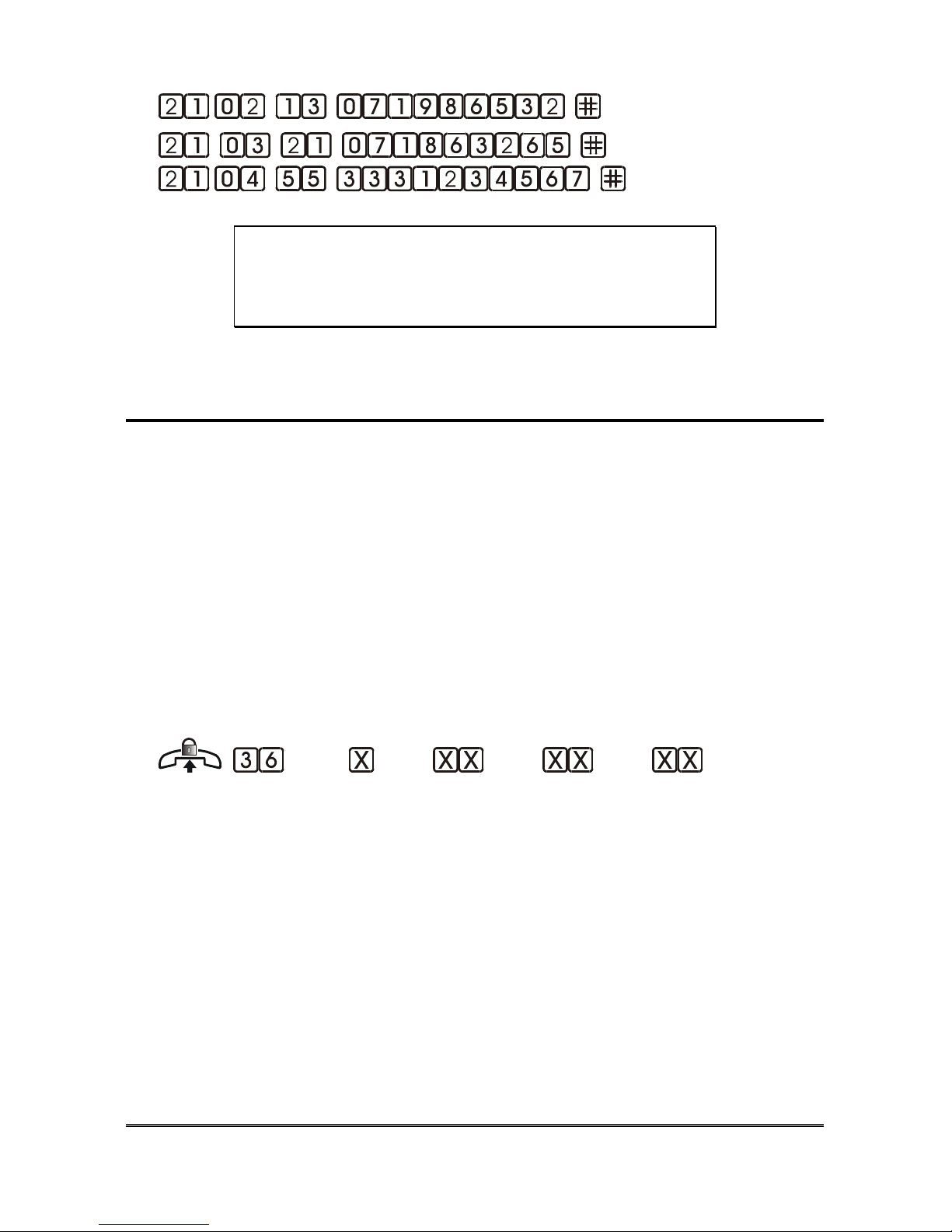
Changing the installer password
Installe
r
Operato
r
9
… (old) … (new)
… (new) [ ]
¾ Lift the handset
¾ Press 91.
¾ Enter the old password (up to 5 digits)
52 PROGRAMMING
¾ Press *.
¾ Enter the new password (up to 5 digits)
¾ Press *.
¾ Enter the new password (up to 5 digits) to confirm
¾ Press *.
Example: to change the INSTALLER PASSWORD from the default
value (0) to 123 dial:
.
WARNING!!
Make a note with the password. If you forget it, you
must contact our technical support center.
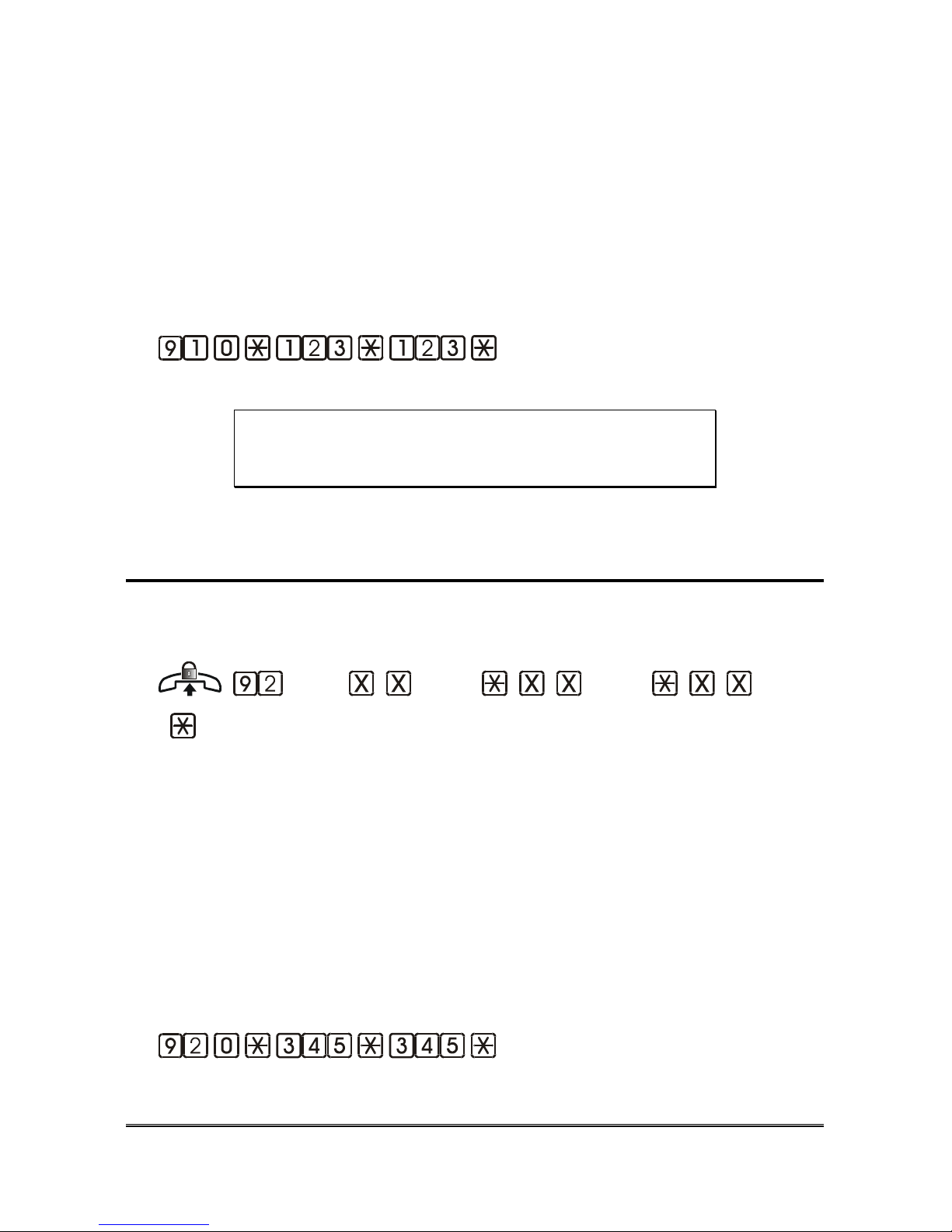
Changing the operator password
Installatore Operatore
9
… (old) … (new) … (new)
[
]
¾ Lift the handset.
¾ Press 92.
¾ Enter the old password (up to 5 digits) and press * .
¾ Enter the new password (up to 5 digits) and press *.
¾ Enter the new password (up to 5 digits) to confirm and #.
Example: To change the OPERATOR PASSWORD from the default
value (0) to 345 dial:
.

PROGRAMMING 53
WARNING!!
Make a note with the password. If you forget it, you
must contact the installer.
Activating the “no power supply” alarm
Installe
r
Operato
r
9
You can activate the alarm and set the minimum time interval without power
supply in order to activate the alarm.
(setting)
¾ Lift the handset.
¾ Press 51.
¾ Enter:
- 00 = disabled alarm
- from 01 to 99 = active, with 1 minute “No power supply” time for
each unit.
Example: to activate the alarm with a delay of 3 minutes dial:
.
Activating the “diagnostics” alarm
Installe
r
Operato
r
9 9
You can activate the Diagnostics procedure and enable the related alarm in case
the procedure should detect any malfunctioning.
( setting)
¾ Lift the handset.

54 PROGRAMMING
¾ Press 54.
¾ Enter:
- 0 to deactivate the diagnostics alarm
- 1 to activate the diagnostics alarm
Note: the diagnostic procedure is performed every day at the same
time set for the automatic test call.
Note: when the diagnostic alarm is enabled, the device always
performs the diagnostic procedure upon switching on.
Expiring credit alarm
Installe
r
Operato
r
9 9
It allows to activate the check procedure on the SIM card remaining credit and
its related alarm, in case the Hepy L300 is connected with a GSM200 module.
The check is performed at the end of each outgoing call, the value acquired is
compared with the minimum value previously set; in case the acquired credit is
lower, the corresponding alarm is generated.
WARNING
The remaining credit request can only be enabled
on pre-paid SIM cards (no contracts accepted)
from the following providers: Tim, Vodafone Italy
and Wind.
Activating the expiring SIM credit alarm
(setting)
¾ Lift the handset.
¾ Press 240.
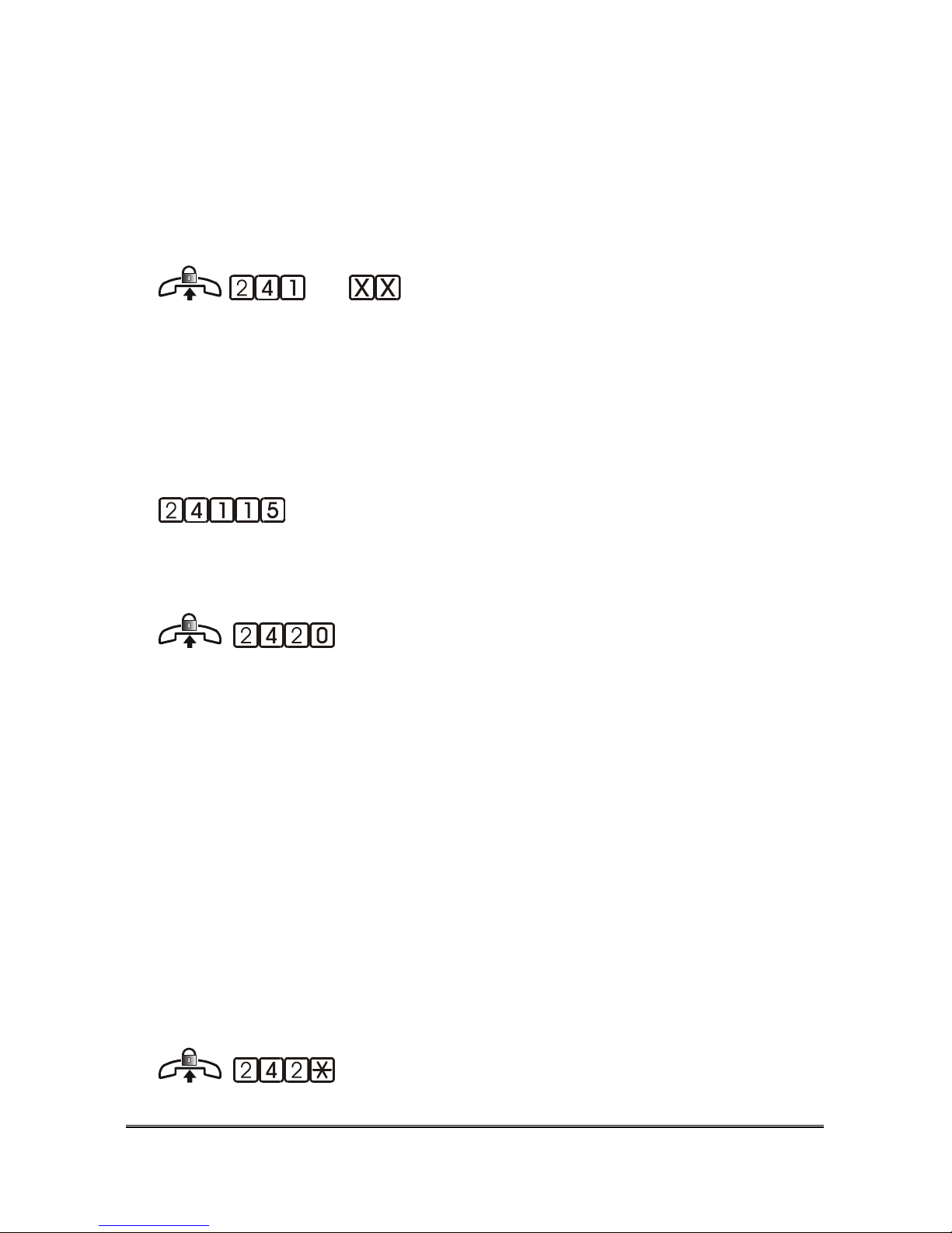
PROGRAMMING 55
¾ Enter:
- 0 to disable the remaining credit request
- 1 to enable the remaining credit request
Programming the minimum credit value
(minimum credit value expressed in
Eur)
¾ Lift the handset.
¾ Press 241.
¾ Enter the minimum credit value expressed in Eur (from 01 to 99)
Example: to program a minimum value equal to 15 Eur dial:
.
Make a remaining credit request now.
¾ Lift the handset.
¾ Press 2420.
Note: this function allows to request immediately the remaining
credit to the GSM provider and generates an immediate
alarm in case the credit should be expiring. Please make sure
the telephone number has been previously set (see page 37)
Listening to the remaining credit value.
It is possible to listen to the remaining SIM credit value directly from the local
telephone.

56 PROGRAMMING
¾ Lift the handset.
¾ Press 242*.
Nota: in order to listen to the remaining credit value, please make
sure that the expiring credit check has been previously
enabled and that at least one remaining credit request has
been performed by Helpy L300
Activating the auxiliary alarm 1
Installe
r
Operato
r
9 9
It allows to enable the input IN2 for the auxiliary technological alarm 1.
(setting)
¾ Lift the handset.
¾ Press 55.
¾ Enter:
- 0 to disable the input for auxiliary technological alarm 1
- 1 to enable the input for auxiliary technological alarm 1
Note: the technological alarm input IN2 is normally open, not
configurable. In order to start the alarm procedure, the
contact must remain closed for a time at least equal to the
minimum activation time set for the emergency call buttons.
Activating the auxiliary alarm 2 / Gong
Installe
rOp
erato
r
9 9
It allows to enable the input IN3 for the auxiliary technological alarm 2 or the
Gong message.

PROGRAMMING 57
(setting)
¾ Lift the handset.
¾ Press 56.
¾ Enter:
- 0 to disable the input
- 1 to enable the input for auxiliary technological alarm 2
- 2 to enable the input for the Gong message
Note: the input IN3 is normally open, not configurable.. In order to
start the alarm procedure, the contact must remain closed for
a time at least equal to the minimum activation time set for
the emergency call buttons.
Note: the Gong message is played by the car’s handsfree terminal
when the contact is closed.
Emergency call button normally closed/open
Installe
rOp
erato
r
9
The emergency call buttons can be programmed as normally closed or normally
open. Programming refers all the emergency call buttons connected to the
system. The individual buttons cannot be configured separately.
(setting))
¾ Lift the handset.
¾ Press 41.
¾ Enter:
0 for normally closed contact;
1 for normally open contact.

58 PROGRAMMING
Note: if you programme the emergency call buttons as normally
closed you must connect the Alarm inputs not used to a
negative pole (for ex. VV1- or VV2-).
Delay for emergency call buttons
Installe
r
Operato
r
9
You can programme the minimum number of seconds for which the emergency
call button must be pressed in order to activate the alarm (2 sec. by factory
default)
(seconds)
¾ Lift the handset.
¾ Press 42.
¾ Enter the value corresponding to the desired delay time (from 2 to 9
seconds).
Filter activation
Installe
r
Operato
r
9 9
The filter is used to avoid sending the alarm (from emergency button 1, in the
car) in the following cases:
• The car is at the floor and all doors are open
• The car is moving and the doors will open at the next floor.
• The filter must be deactivated during maintenance.
The filter has no effect on buttons 2 and 3, if present.
(setting)
¾ Lift the handset.
¾ Press 53.
0 to disabile the filter
1 to enable the filter.
PROGRAMMING 59
Note: if the filter is enabled and the filter input is active (doors are
open or the elevator car is moving and doors are going to
open at the next floor), the alarm does not start when pressing
the emergency call button. If any, technological alarms or the
automatic test procedure are temporarily suspended to permit
HelpyL300 to record the emergency call alarm and resumed
immediately afterwards.
Warning
The filter input must be disabled during
maintenance operations of the elevator system.
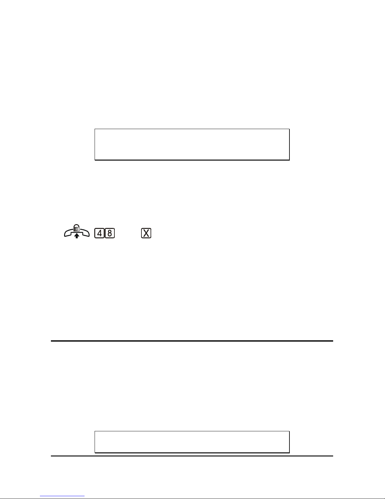
Programming the filter input as normally closed / open
It allows to program the filter input as normally open or normally closed.
(setting)
¾ Lift the handset.
¾ Press 48.
¾ Enter:
0 for normally closet contact;
1 for normally open contact.
Codes for alarms’ management
You can customize the codes used for managing the alarms differently from the
factory-default settings:
− “ACKNOWLEDGE” CODE: by default 5
− “HANDSFREE ACTIVATION” CODE: by default 0.
− “END” CODE: by default 9
− “EXCLUSION” CODE: by default 1.
WARNING
Each code must be different from all others

60 PROGRAMMING
“ACKNOWLEDGE” CODE
It is the code that must be dialed by the user who answers the emergency call to
listen to the alarm and elevator identification message (5 by factory default).
Installe
r
Operato
r
9
… (from 1 to 3 digits)[ ]
¾ Lift the handset.
¾ Press 47.
¾ Enter the “Acknowledge” code. If the code’s length is less than 3 digits
dial #.
Note: if you don’t dial this code after answering the alarm call, the
elevator identification message will be automatically heard
within 10 seconds.
Nota: upon alarm, you can listen again to the elevator identification
message at any time simply by pressing the “Acknowledge”
code.
“HANDSFREE ACTIVATION” CODE UPON ALARM
It’s the code that can be dialled by the called user to establish the handsfree
conversation with the person who has asked for help. If the called user does not
dial this code the handsfree connection is automatically established after about
30 seconds. By factory default it is set at 0.
Installe
r
Operato
r
9
… (from 1 to 3 digits) [ ]
¾ Lift the handset.
¾ Press 45.

PROGRAMMING 61
¾ Enter the “Handsfree activation” code. If the code’s length is less than 3
digits dial #.
“END” CODE UPON ALARM
It is the code entered by the called remote user to abort the alarms. By factory
default it is set at 9.
Installe
r
Operato
r
9
… (from 1 to 3 digits) [ ]
¾ Lift the handset.
¾ Press 43.
¾ Enter the “End” code. If the code’s length is less than 3 digits dial #.
Note: For the emergency call alarm, it is possible to end the alarm
only after entering the “Exclusion” code (1 by default).
“EXCLUSION” CODE UPON ALARM
It’s the code that must be dialled by the called user in order to:
• exclude his number from the next alarm call cycles in case of technological
alarms, diagnostics, automatic test call;
• Suspend the emergency call alarm .
It is set at 1 by factory default.
Installe
r
Operato
r
9
… (from 1 to 3 digits) [ ]
¾ Lift the handset.
¾ Press 44.

62 PROGRAMMING
¾ Enter the “Exclusion” code. If the code’s length is less than 3 digits dial
#.
Recording/playing the courtesy message
The courtesy message is the message played by the handsfree when the help
call button is pressed to reassure the people trapped in the elevator. The device
is supplied with a pre-recorded courtesy message (Italian/English) that can be
changed by the user.
Note: in case the courtesy message should be modified, the pre-
recorded one will no longer be available.
RECORDING THE COURTESY MESSAGE
Installe
r
Operato
r
9
(message) (beep) (recording)(beep)
¾ Lift the handset.
¾ Press 7102.
¾ Record the message (max 22 seconds).
¾ Hang up at the end of the message.
Note: it is not compulsory to use all available seconds for correct
recording.
Note: a beep indicates that the recording time has elapsed.
PLAYING THE COURTESY MESSAGE
Installe
r
Operato
r
9 9
(message) (playback)
¾ Lift the handset.

PROGRAMMING 63
¾ Press 7202. You will listen to the message.
Handsfree connection time upon alarm
Installe
r
Operato
r
9
The handsfree connection has a limited duration. It can be programmed from 1
to 9 minutes. When the time has almost expired, the system sends a warning
tone to the called user. The called user has a few seconds to extend the
connection by the programmed time value by dialling any digit (different from
the “Exclusion code”, 1 by default, from the “End” code, 9 by default, and from
the “Acknowledge” code, 5 by default).
The conversation time can be extended indefinitely.
(MINUTES)
¾ Lift the handset.
¾ Press 46.
¾ Enter the maximum time (1, 2 , … 9 minutes) for the handsfree
conversation.
Example: To set the connection time at 6 minutes dial: .
Pulse or DTMF dialling
Installatore Operatore
9
You can set the type of dialling over the external line.
(setting)
¾ Lift the handset.
¾ Press 61.
¾ Enter :
- 0 for pulse dialling

64 PROGRAMMING
- 1 for DTMF dialling.
Call cycles
Installe
r
Operato
r
9
It permits to programme the number of call cycles made by the device in case
of :
- technological alarms,
- diagnostic alarms
- expiring SIM credit alarms
- automatic test calls.
By factory default the number of call cycles is set at 5. The number of call
cycles is always indefinite for emergency call alarms.
(cycles)
¾ Lift the handset.
¾ Press 62.
¾ Enter the number of alarm call cycles (from 0 to 9). “0” indicates 10 call
cycles.
Example: To set the call cycles at 5 dial: .
Connection to switchboard or PSTN line
Installe
r
Operato
r
9
It allows to indicate whether the device is connected to a PABX or directly to
the fixed line (as per factory default setting). This setting is required for the
device to encode correctly the tones coming from the external line connector
LTI.
(setting)

PROGRAMMING 65
¾ Lift the handset.
¾ Press 67.
¾ Enter
- 0 if the system is connected to a switchboard extension
- 1 if it is connected to the PSTN line.
Note: When the system is connected to a switchboard, the external
line seize code of the switchboard must be dialled before the
programmed number.
Automatic answer
Installe
r
Operato
r
9
The device can automatically answer the incoming calls over the external line.
You can programme the device by remote with a DTMF telephone, open a door
or establish a handsfree conversation with the handsfree terminals.
Activation
(number of call rings)
¾ Lift the handset.
¾ Press 64.
¾ Enter the number of rings (from 0 to 9) before the alarm system
engages the line to answer the call (automatic answer). “0” sets the
number of rings at 10. The factory default setting is 1.
Connection Time after the Automatic Answer
You can set the maximum connection time after the automatic answer. When
the time has almost expired, the system sends a warning tone to the external
user. The user has a few seconds to enter any digit and extend the connection
by the programmed time value. By factory default it is set at 1 minute.

66 PROGRAMMING
(MINUTES)
¾ Lift the handset.
¾ Press 65.
¾ Enter the number of minutes (from 1 to 9) for the connection after the
automatic answer.

USE OF OTHER FUNCTIONS 67
USE OF OTHER FUNCTIONS
Following is the description of HelpyL300 local and remote use.
The icon
indicates that the feature is available by simply lifting the
handset of the local telephone connected with Helpy L300;
The icon
indicates that the feature is available only after inserting the
password (*0# by default). If, by lifting the handset of the local telephone, you
hear the dialling tone (one long tone followed by a shorter one) this means that
the key word has already been inserted. Otherwise you need to insert it.
LOCAL USE
Conversation between the local telephone and the
car
Installe
r
Operato
r
9 9
You can establish a conversation with the handsfree 1 in the car from the local
telephone.
(conversation)
¾ Lift the handset.
¾ Conversation is automatically established with the car’s handsfree 1
Note: the maximum conversation time with the car is 10 minutes.
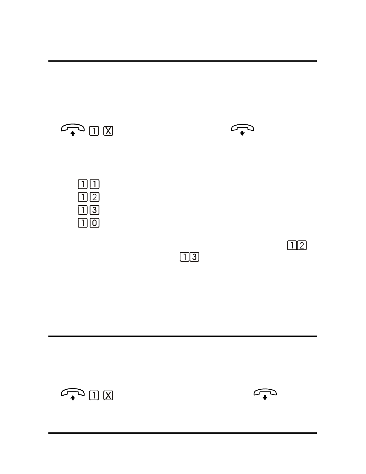
68 USE OF OTHER FUNCTIONS
Conversation between the local telephone and the
handsfree selected by the user
Installe
r
Operato
r
9 9
The local telephone can be used to have a conversation with any of the
handsfree terminals connected to the device. This is also possible in the
programming mode.
(handsfree) internal call
¾ Lift the telephone handset.
¾ Press:
Activate Handsfree 1;
Activate Handsfree 2;
Activate Handsfree 3.
Deactivate all.
Example: to speakt to handsfree 2 pick up the handset and dial
;
now to speak to handsfree 3 dial
, event without hanging up.
Handsfree 2 and 3 can be used only if the installation type has been
programmed accordingly.
Note: the maximum conversation time with each handsfree is 10
minutes.
Testing the handsfree terminals
Installe
rOp
erato
r
9 9
It allows to check the correct operation of the hands-free terminals, even during
programming operations.
(setting) (tone) internal call
¾ Lift the handset.
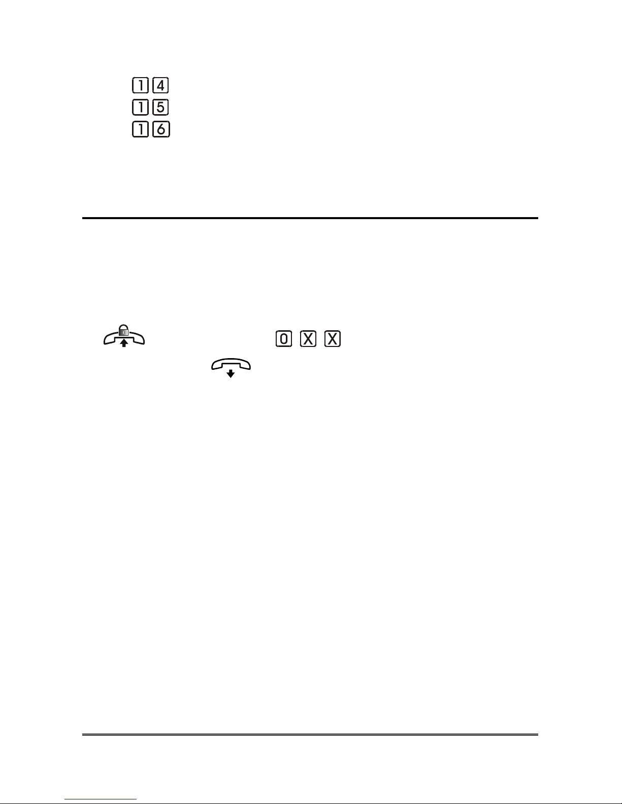
USE OF OTHER FUNCTIONS 69
¾ Press:
to check handsfree 1;
to check handsfree 2;
to check handsfree 3.
¾ If you hear a tone and then the conversation is establiished with the
selected handsfree , the test result is OK.
Making an outgoing call from the local telephone
Installe
rOp
erato
r
9 9
It allows to make an external call both via PSTN line and via GSM line (with
GSM200 module only) from the local telephone connected to the Helpy L300.
The password (installer or operator) must have been previously entered.
(dialling tone) … (telephone number)
outgoing call
¾ Lift the handset.
¾ If you hear the dialling tone , this means you are already in programming
mode, otherwise, you need to access programming by dialling : * <operator
or installer’s password> #.
¾ Press 0.
¾ In case of PSTN line, the dialling tone will be heard; in case of GSM200
module the Helpy L300’s dialling tone will be heard.
¾ Dial the desired telephone number.
¾ At the end of the call enter the password again to exit, in order to avoid
unauthorized people from making outgoing calls (by the way Helpy L300
exits automatically after 30 minutes).
Note: in case of GSM200 Module, you must wait for 10 seconds
after dialing the telephone number before you receive the
confirmation tone informing that the call is sent.
.

70 USE OF OTHER FUNCTIONS
Opening doors
It allows to activate relays RL1 and RL2. The password must have been
inserted.
Installe
r
Operato
r
9 9
¾ Lift the handset
¾ If you hear the dialling tone you don’t need to insert the password,
otherwise dial * <INSTALLER or OPERATOR PASSWORD> # (by default:
*0#).
¾ Press:
= Relay 1
= Relay 2
Example: to open the door associated with relay 1 , dial:
.
¾ At the end of the call enter the password again to exit, in order to avoid
unauthorized people from opening the doors. HelpyL300 exits
automatically after 30 minutes.
REMOTE USE WITH HELPYL300 IN STAND-BY MODE
You can call the device from a remote telephone (mobile or DTMF telephone)
to:
• programme it
• make a handsfree connection
• check the handsfree status
• open doors.
The Automatic Answer function must be active (this function is active by
default).
The procedure is as follows:
¾ Make a call to HelpyL300. When the device answers the call, the user
hears a short series of DTMF tones followed by the elevator
identification message and the dialling tone.
¾ After the message dial * <INSTALLER or OPERATOR PASSWORD> #
(by default:
).

USE OF OTHER FUNCTIONS 71
If the codes are correct, the user hears the confirmation tone (one short DTMF
tone for three times) or the error tone (one DTMF tone for three times). It is
now possible to access the following features.
Conversation with a handsfree terminal selected
by the user.
Installe
r
Operato
r
9 9
¾ Dial:
Activate handsfree 1;
Activate handsfree 2;
Activate handsfree 3.
Deactivate all.
The activation of handsfree 2 or 3 depends on the type of installation previously
set.
Note: the handsfree connection has a limited time. When the time
has almost expired, the system sends a warning tone to the
external user. The user has a few seconds to enter any digit
and extend the connection by the programmed time value.
.
Testing the handsfree terminals
Installe
rOp
erato
r
9 9
¾ Dial:
to check handsfree 1;
to check handsfree 2;
to check handsfree 3.
¾ If you hear a tone and then the conversation is establiished with the
selected handsfree , the test result is OK.

72 USE OF OTHER FUNCTIONS
Opening the doors
Installe
r
Operato
r
9 9
¾ Dial:
= Relay 1
= Relay 2
REMOTE USE WHILE THE EMERGENCY CALL ALARM IS
SUSPENDED
While the emergency call alarm is suspended it is possible, by calling Helpy
L300 remotely, to perform the following operations:
• Establish a handsfree connection with the person who called for help
• Reset the emergency alarm by remote
• Establish a handsfree connection with the other handsfree devices installed
in the system, if any
• Open the doors
Following are the procedures for each feature.
Handsfree connection and door opening
While the emergency call alarm is suspended:
¾ Call Helpy L300 remotely
As soon as Helpy L300 answers the call a handsfree connection is
automatically established with the person who called for help (without any need
to insert the password).
It is then possible to insert the codes to open the doors or connect to the other
handsfree devices installed in the system, if any. (please see “Remote use with
HelpyL300 in stand-by mode”).
Resetting the emergency call alarm by remote
This procedure allows to reset an emergency call alarm, which has previously
been suspended, by remote.
¾ Make a call to Helpy L300 by remote.

USE OF OTHER FUNCTIONS 73
¾ After hearing the messages, the conversation is automatically set up with
the trapped person.
¾ Dial
<installer or operator password> . By default, the password is :
.
¾ Press
. The confirmation tone will be heard.
¾ Dial the “End” code (
by default). The telephone line will be
disconnected.

74 USE OF OTHER FUNCTIONS
ADEMCO CONTACT ID PROTOCOL
Following are the details concernine the use of the Ademco Contact ID
protocol.
The data format is as follows:
ACCT MT QXYZ GG CCC S
Each field is explained in the following table:
FIELD MEANING USE BY HELPYL300
ACCT
4 Digit Account number (0-9)
See “Programming the protocols
identification code”. Letters can
not be used.
MT
Message Type Always set to 18
1= New Event
or Opening
Used for any new alarm event.
3= New
Restore or
Closing
Used only for emergency alarm
reset by the local telephone (upon
the call which notifies the alarm
end)
Q
Event
qualifier
6= Previously
reported
condition still
present
Not used
140= Emergency call
301 = No power supply
302 = Dead battery
307 = Diagnostics
330 = Alarm from the elevator
CPU
380 = Auxiliary alarm
XYZ
Event code
600 = Automatic test
GG
Group Always set to 00
CCC
Zone Always set to 000
S
Checksum Checksum

MAINTENANCE 75
MAINTENANCE
The device does not contain parts that require maintenance or user-replaceable
parts. Exception is made for the battery protection fuse.
Contact the service centre in case of malfunction.
Check the battery charge status periodically.
Contact the technical service if normal operation is not restored.
WARNING:
The filter input must be disabled during
maintenance operations of the elevator system.
FUSE REPLACEMENT
¾ Disconnect the device from the 230V mains.
¾ Open the device by loosening the upper screw.
¾ Disconnect the battery.
¾ Remove the fuse and replace it.
¾ Connect the battery.
¾ Close the device.
¾ Connect the device to the 230V mains.

76 QUICK GUIDE – PROGRAMMING
QUICK GUIDE – PROGRAMMING
In the following tables:
− INST indicates that the programming is allowed to the INSTALLER;
− OPER indicates that the programming is allowed to the
OPERATOR.
− The default settings are written in bold.
BASIC PROGRAMMING
BASIC PROGRAMMING
ACCESS TO
PROGRAMMING
<INSTALLER or OPERATOR PASSWORD>
(by default:
)
EXITING THE
PROGRAMMING
<INSTALLER or OPERATOR PASSWORD>
(by default:
)
PSTN
TYPE OF
TELEPHONE
LINE
GSM200 module
SOURCE: RECEIVER:
emergency
call
ADEMCO
technological
and
diagnostic
alarm
USER
ESSE-TI
automatic
test call
CLI
TELEPHONE
NUMBERS
(
POSITIO
N FROM
01 to 12)
expiring
SIM credit
SMS
… (tel.
number.
max 20
digits)

QUICK GUIDE – PROGRAMMING 77
BASIC PROGRAMMING
Week day :
SUNDAY
MONDAY
TUESDAY’
WEDNESDAY
THURSDAY
FRIDAY
DATE
SATURDAY
(dd) (mm) (yy)
HOUR
(hhmm) from 0000 to 2359
ID message (22 sec.)
RECORD
MESSAGES
courtesy message (22
sec.)
(beep) Record
ID message
LISTENING TO
MESSAGES
courtesy message
(listen)
= 1 hands-free;
= 2 hands-free;
TYPE OF
INSTALLATION
= 3 hands-free.
= DISABLED NO POWER
SUPPLY ALARM
(INST)
from 01 to 99 = ENABLED ALARM with XX
minutes delay
= DISABLED
DEAD BATTERY
ALARM
(INST)
= ENABLED
= DISABLED
DIAGNOSTICS
ALARM
(INST/OPER)
= ENABLED
= DISABLED
AUXILIARY 1
ALARM
(INST/OPER)
= ENABLED

78 QUICK GUIDE – PROGRAMMING
BASIC PROGRAMMING
= DISABLED
= ENABLED
AUX. 2 ALARM /
GONG
(INST/OPER)
= ENABLED GONG
ADEMCO
PROTOCOL ID
(INST)
4 DIGITS ID:
ESSE_TI
PROTOCOL ID
(INST)
10 DIGITS ID:
Frequency
(days 1-9)
Time
(hhmm) from 0000 to 2359
AUTOMATIC TEST DISABLED
Activation
AUTOMATIC TEST ENABLED
AUTOMATIC
TEST DATA
(INST)
Making a manual
test call
= ALLARME DISABILITATO
Activation
= ALLARME ABILITATO
Min. value
(min. credit value in Eur)
Making a manual
call
EXPIRING
CREDIT
(INST/OPER)
Credit listening
HANDSFREE 1
HANDSFREE 2
HANDSFREE
VOLUMES
HANDSFREE 3
... (loudspeaker’s
volume)
... (mocrophone’s
sensitivity.)
MESSAGES
DAY GONG
MESSAGES
VOLUMES
NIGHT GONG
... (volume)
LISTENING TO
PROGRAMMING
... (prefix programming code)
RESTORING
FACTORY
DEFAULT

QUICK GUIDE – PROGRAMMING 79
ADVANCED PROGRAMMING
ADVANCED PROGRAMMING
CHANGING THE
INSTALLER
PASSWORD
(INST)
… (old)
.. (new) .. (new)
CHANGING THE
OPERATORPASSWOR
D
(INST)
… (new)
.. (new) .. (new)
=CLOSED
EMERGENCY BUTTON
NORMALLY
OPEN/CLOSED
(INST)
= OPEN
EMERGENCY BUTTON
DELAY
(INST)
2 to 9 seconds
= DISABLED
FILTER
(INST/OPER)
= ENABLED
= NORMALLY CLOSED
FILTER INPUT
NC/NA
(INST/OPER)
= NORMALLY OPEN
“ACKNOWLEDGE”
(INST)
… (1 to 3 digits) [ ]
“HANDSFREE
ACTIVATION”
(INST)
… (1 to 3 digits) [ ]
“END”
(INST)
… (1 to 3 digits) [ ]
“EXCLUSION”
(INST)
… (1 to 3 digits) [ ]
HANDSFREE
CONNECTION TIME
UPON ALARM
(INST)
MINUTES, 2 to 9
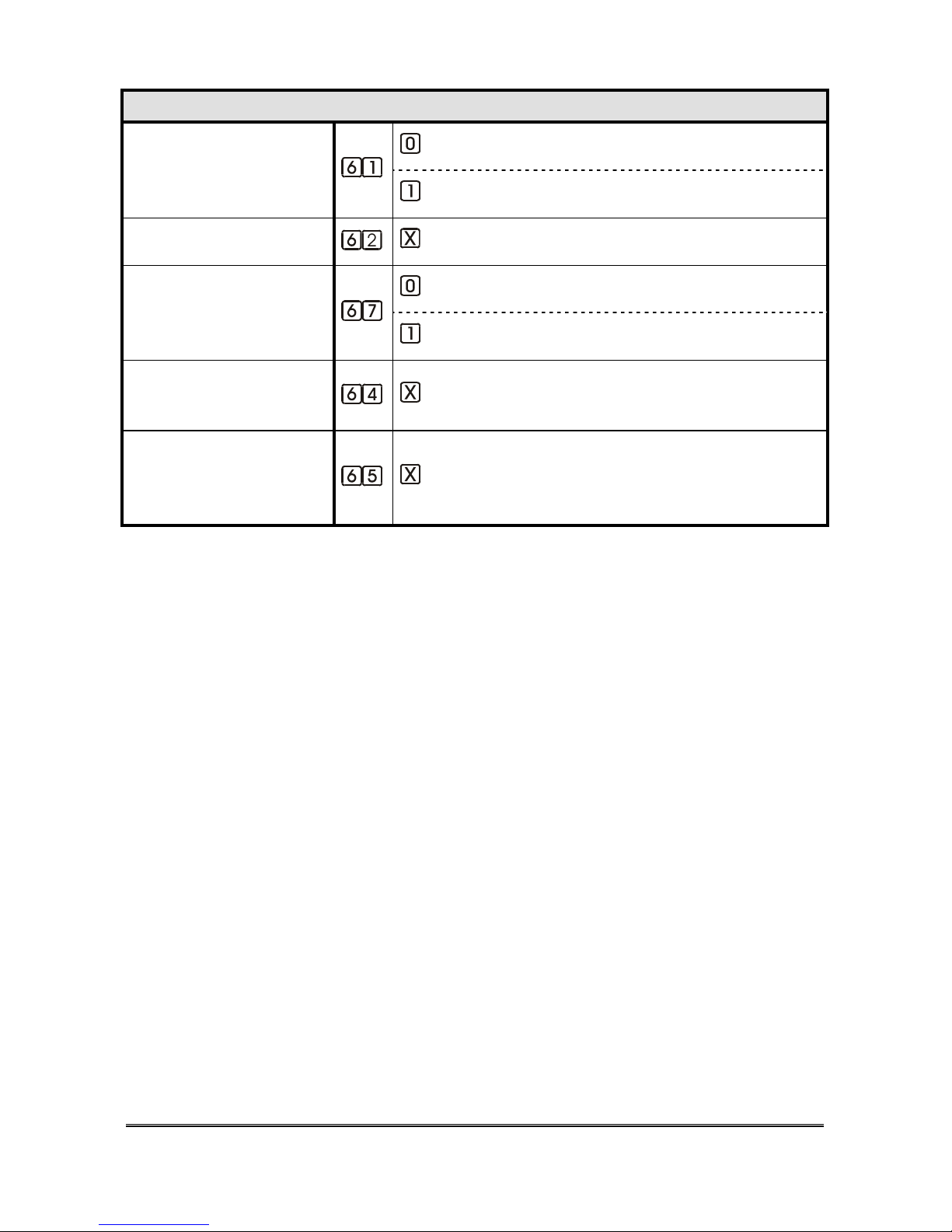
80 QUICK GUIDE – PROGRAMMING
ADVANCED PROGRAMMING
= PULSE
PULSE/DTMF
DIALLING
(INST)
= DTMF
CALL CYCLES
(INST)
(cycles from 0 to 9; 0=10 cycles)
= PABX
PABX/PSTN line
CONNECTION
(INST)
= PSTN line
AUTOMATIC
ANSWER
(INST)
(ring number, from 1 to 9; 0=10 ring)
CONNECTION TIME
AFTER AUTOMATIC
ANSWER
(INST)
(MINUTES from 1 to 9)
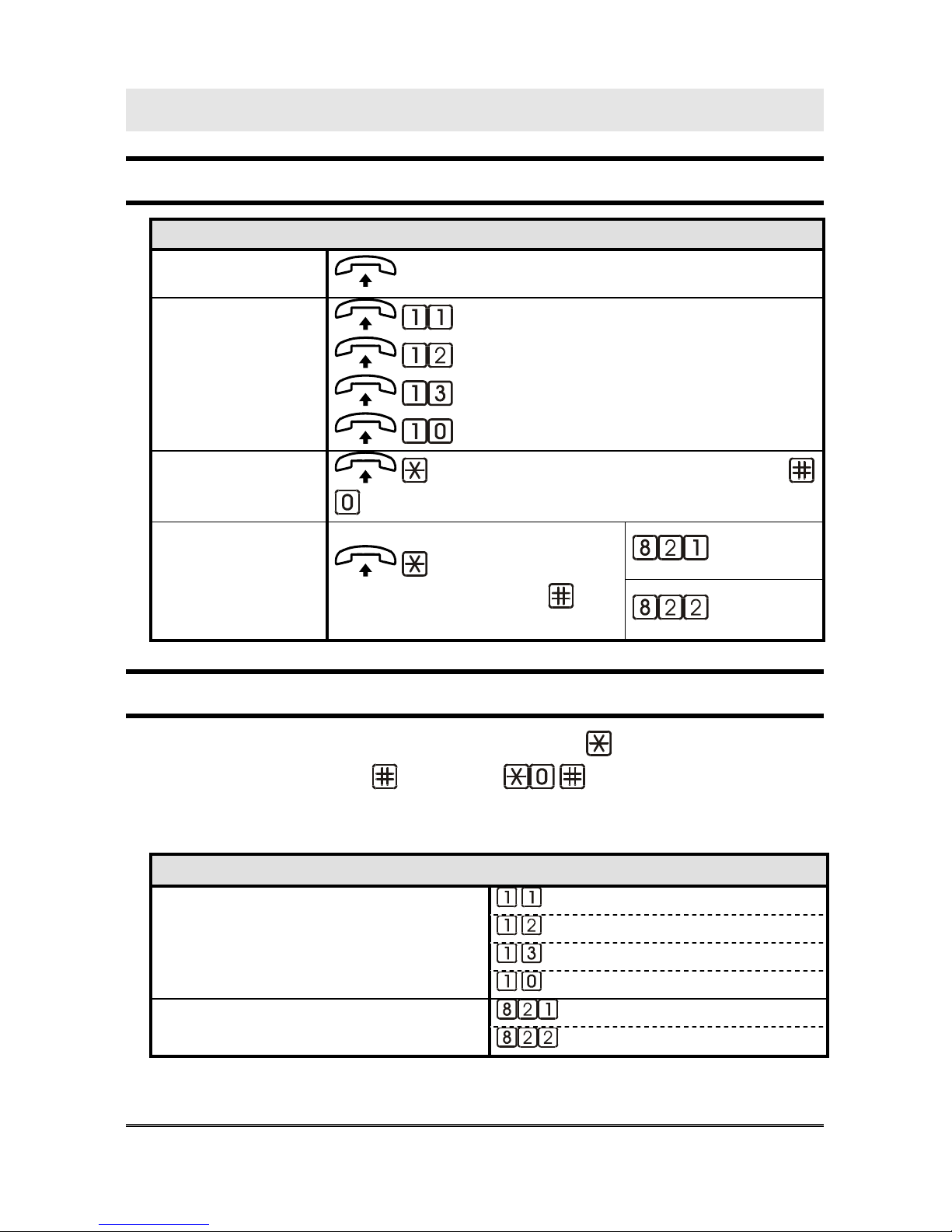
QUICK GUIDE – USE 81
QUICK GUIDE – USE
LOCAL
LOCAL USE
CONVERSATION
WITH THE CAR
CONVERSATION
CONVERSATION
WITH ONE
HANDSFREE
TERM.
= HANDSFREE 1
= HANDSFREE 2
= HANDSFREE 3
= DEACTIVATE ALL
OUTGOING
CALLS
<INSTALLER OR OPERATOR PASSWORD>
<TELEPHONE NUMBER>
RELAY’ 1
RELAYS
<INSTALLER OR
OPERATOR PASSWORD>
RELAY 2
REMOTE USE WITH HELPYL300 IN STAND-BY
Call HelpyL300 and wait for the answer. DAIL: <INSTALLER OR
OPERATOR PASSWORD>
(by default: ).
BESIDES THE PROGRAMMING, THE FOLLOWING SERVICES ARE
AVAILABLE:
REMOTE USE WITH HELPYL300 IN STAND-BY
= HANDSFREE 1
= HANDSFREE 2
= HANDSFREE 3
CONVERSATION WITH ONE
HANDSFREE TERM.
= DEACTIVATE ALL
= RELAY 1
DOOR OPENER RELAY
= RELAY 2
82 TECHNICAL SPECIFICATIONS
TECHNICAL SPECIFICATIONS
Tones
Dialling
Busy
Confirmation and warning connection time elapsed
Error from local
Error from remote
Status indicator LED’s
Normal operation – no alarm, filer disabled
Normal operation – no alarm, filer enabled
Alarm in progress

TECHNICAL SPECIFICATIONS 83
GSM Signal indicator LED’s (only with GSM200
module)
Normal operation, no signal
Normal operation, low signal
Normal operation, medium signal
Normal operation, high signal
Power supply
Power used....................................................................................................16W
Mains voltage ......................................................................... 230V ~+5% -10%
Buffer battery................................................................................ 12V 2A/h max
Expected operation time with a new 2A/h battery in idle state...............40 hours
Voltages.............................................................................. +3.3V,+5V, +13.8 V
Overvoltage protection and battery fuses
Self-restorable fuse on electrical mains
Signalling system
Pulse or DTMF dialling over external line
Pulse ratio ......................................................................................60/40 +/- 10%
Pulse frequency.............................................................................. 10Hz +/- 10%
Tone generator............................................................................ 659 Hz, 740 Hz
External line tone recognition................................................................... 425 Hz
HANDSHAKE tone recognition ............................................ 1400 Hz, 2300 Hz

84 TECHNICAL SPECIFICATIONS
Voice messages
Voive messages ................................................................................................60
Total recording time ................................................................................... 4 min
Elevator ID message........................................................................customizable
Courtesy message broadcast in the car ............................................customizable
Data transmission / communication
In-built modem ............FSK 1200 Tx/Rx – point to point 9600 baud over GSM
Serial plug for connection to elevator CPU.................................................. TTL
Protocols
Tele-programming protocol...................................................... PROPRIETARY
Elevator control protocol .......................................................... PROPRIETARY
Service centre protocol ............................................Ademco Contact ID, Esse-ti
Telephone terminations
Connections to public telephone network...........................................................1
Connections for extensions.....................................................................1 (RJ11)
Connections for handsfree terminals ..................................................................3
Outputs for doorkeeper telephone.......................................................................1
Connections to proprietary GSM200 device...........................................1 (RJ45)
Connections
Internal line – External telephone line
Internal line - Handsfree
External telephone line – Handsfree
Inputs/ Outputs
Alarm input.........................................................................................................3
Auxiliary input....................................................................................................2
Auxiliary input (filter) ........................................................................................1
Outputs (alarm given indicator light and recorded alarm indicator light)...........2

TECHNICAL SPECIFICATIONS 85
Signalling LED...................................................................................................2
Outputs for door open relay.............................................................. 2 (24V 1A)
Safety system
EEPROM memory for data protection in case of power failure...........................
Watch-dog system ................................................................................................
Other characteristics
Cooling .............................................................................. by natural convection
Temperatura di funzionamento.............................................................0° ~ 50°C
Dimensions...............................................................................160x180x80 mm.
Weight .........................................................................................................1 Kg.
CE CONFORMITY DECLARATION
Esse-ti s.r.l., with registered seat in Zona Ind. Squartabue, I-62019 Recanati
(MC), Italy, hereby declares that this device complies with the following
standards:
• TBR21 (Attachment requirements for pan-European approval for
connection to the analogue Public Switched Telephone Network
(PSTNs) of TE)
• EN50082-1, EN55022 (Electromagnetic compatibility)
• EN41003, EN60950 (Electric safety)
• EN 81-28:2004 (Safety rules for contruction and installation of lifts –
Lifts for the transport of persons and goods – Part 28: Remote
alarm on passengers and goods passenger lifts)
• EN 81-70:2004 Safety rules for the construction and installations of lifts
- Particular applications for passenger and good passengers lifts -
Accessibility to lifts for persons including persons with disability
and with the requirements of the 1999/5/CE Directive issued by the European
Parliament and by the Council on 9 March 1999 on radio sets,
telecommunication terminals and the mutual acknowledgement of their
conformity.
Conformity with these requirements is expressed with

Helpy L300
25/03/2008
 Loading...