

Esse-ti HELPY GSM-RM, HELPY GSM Quick Manual

14/12/2018
Alarm system for elevators
QUICK GUIDE
Page 2 DESCRIPTION
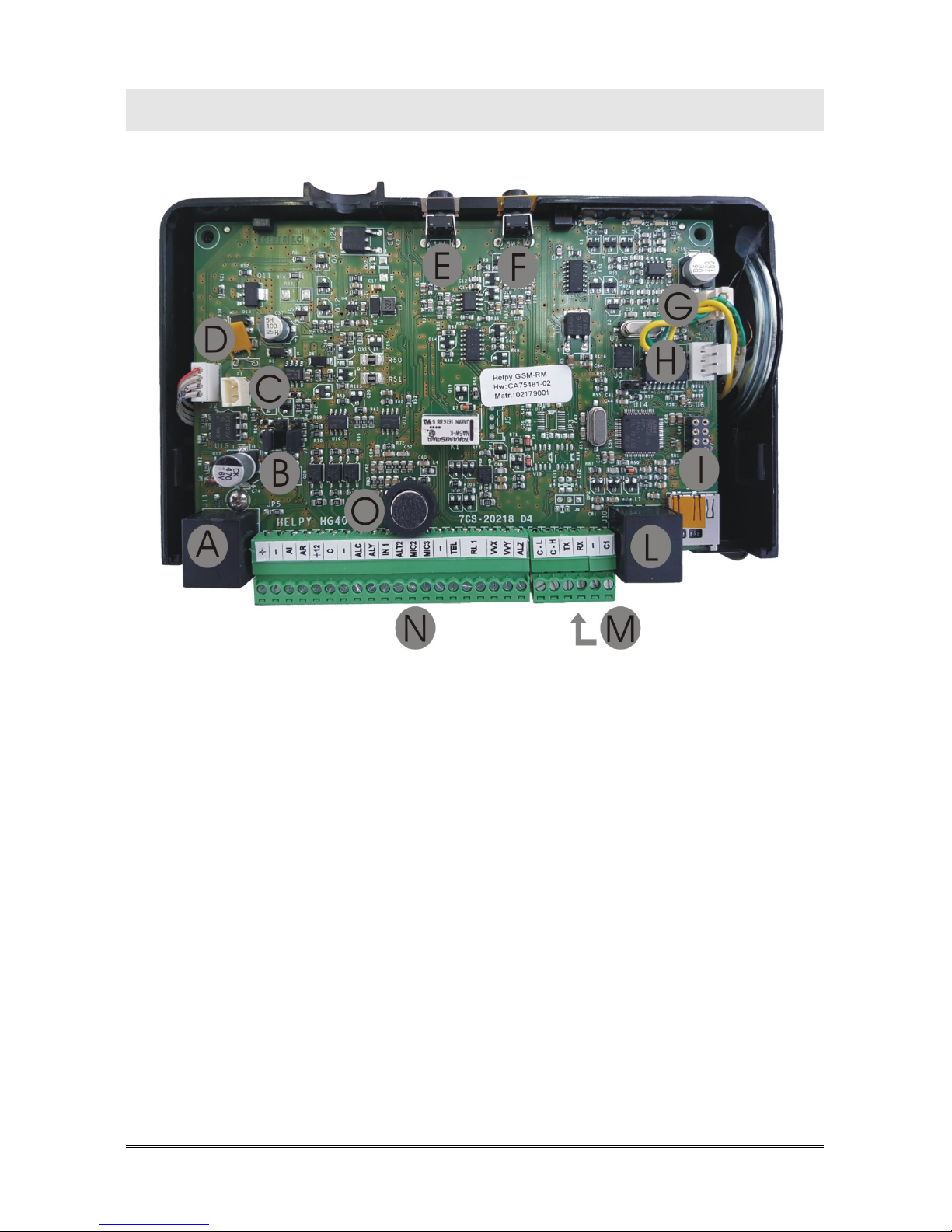
DESCRIPTION
A RJ45 connector for GSM satellite
B Jumper JP2 for define the behaviour of output AI
Jumper JP4 for define the behaviour of output AR
C Built-in backup battery connector
D Internal power-supply connector
E Reset pushbutton
F Alarm pushbutton
G Built-in loudspeaker connector
H Serial port for PC connection
I Micro SD Card slot
L RJ11 connector for local telephone
M Battery compartment door
N Terminal blocks
O Built-in microphone

DESCRIPTION Page 3
LED HELPYGSM-RM
LED signalling alarm / periodical test call (yellow)
LED signalling GSM signal strength (green)
(not used)
LED signalling power supply status (blue)
LED GSM SATELLITE
red LED signalling GSM status
green LED signalling GSM signal strength

Page 4 DESCRIPTION
Terminal blocks
N. NAME DESCRIPTION
01 + 12 VDC OUTPUT (max. 100 mA)
02 –
NEGATIVE POLE
03 AI GIVEN ALARM INDICATOR LIGHT (PNP/NPN by means of jumper JP2)
04 AR RECEIVED ALARM INDICATOR LIGHT (PNP/NPN by means of jumper JP4)
05 +12 12 VDC OUTPUT (max. 100 mA)
06 C COMMON TERMINAL FOR INPUT ALC
(1)
07 – NEGATIVE POLE
08 ALC ALARM INPUT FOR THE ELEVATOR CAR
(2)
09 ALY ALARM INPUT FOR THE PIT
(3)
10 IN1 FILTER INPUT
11 ALT2
OUTPUT FOR CONNECTING THE LOUDSPEAKER OF A PASSIVE SPEAKER
UNIT
12 MIC2
INPUT FOR CONNECTING THE MICROPHONE OF A PASSIVE SPEAKER
UNIT OR A SINGLE MICROPHONE
13 MIC3
INPUT FOR CONNECTING THE MICROPHONE OF A PASSIVE SPEAKER
UNIT OR A SINGLE MICROPHONE
14
–
NEGATIVE POLE
15 TEL LOCAL TELEPHONE
16 RL1 RELAY
(4)
17 RL1 RELAY
(4)
18 VVX OUTPUT FOR CONNECTING AN ADDITIONAL ACTIVE SPEAKER UNIT
19 VVY OUTPUT FOR CONNECTING THE PIT ACTIVE SPEAKER UNIT
20 ALZ ADDITIONAL ALARM INPUT
(3)
OR AUXILIARY INPUT
(4)
21 C-L CAN-BUS
22 C-H CAN-BUS
23 TX RS-232
24 RX RS-232
25
–
NEGATIVE POLE
26 C1 COMMON TERMINAL FOR INPUT IN1
(1)
(1)
: can be connected to a block –, to the block +12 or to an external reference
(2)
: allows to connect voltage free contact pushbuttons (NO or NC) or powered
pushbuttons
(3)
: allows to connect voltage free contact pushbuttons (NO)
(4)
: free contact NO
INSTALLING Page 5
INSTALLING
INSTALLING THE ANTENNA AND INSERTING THE SIM
CARD IN THE GSM SATELLITE
Before proceeding, make sure the device is off and use all due precaution to
avoid electrostatic discharge.
Remove the GSM satellite cover.
Screw the antenna in the appropriate connector (take care to only rotate
the metal ferrule to fix the antenna; do not rotate the antenna on itself).
Push the SIM Card housing cover as indicated by the arrow OPEN until it
unlocks and lift it.
Carefully slide the SIM Card into its housing cover.
Lower the SIM Card housing cover and push it as indicated by the arrow
LOCK until it locks in place.
Close the GSM satellite cover.
ATTENTION
It is not required to remove the PIN code prior to
the use of the HelpyGSM-RM.
The PIN code can be entered, if necessary, by
setting parameter 282.
ATTENTION
In order to avoid damage, never power up the
device without having first installed the antenna.
CONNECTING THE GSM SATELLITE
Connect the RJ45 connector of the GSM satellite to the RJ45 connector
of the HelpyGSM-RM (A in the picture at page 2) by means of the
supplied cable.

Page 6 INSTALLING
CONNECTING THE SPEAKER UNITS
HelpyGSM-RM comes with a built-in active speaker unit.
It is also possible to connect to the HelpyGSM-RM:
- up to 2 independent active speaker units
- up to 2 passive speaker units (or cables with microphone) combined to the
integrated active speaker unit.
It makes HelpyGSM-RM extremely flexible and allows to realize many
different types of installation.
Note:
an active speaker unit allows to realize an independent voice
point with dedicated pushbutton.
Note:
a passive speaker unit must be connected to an active speaker
unit and allows to double it. The passive speaker unit can be
installed at max 6 m distance from HelpyGSM-RM (or from
another active speaker unit) by using a shielded cable.
Note:
in case of connection of active speaker units, the type of
installation must be defined (by setting parameters 63 and
73).
Connect the speaker units (beware of terminal polarity):
ACTIVE SPEAKER UNIT term. blocks HELPYGSM-RM terminal blocks
+ VVY or VVX
– –
PASSIVE SPEAKER UNIT term. blocks HELPYGSM-RM terminal blocks
A ALT2
B MIC2 or MIC3
– –
Examples of types of installation
Installation with passive speaker unit in the elevator car
bottom
DEVICE
SPEAKER UNIT
terminal blocks
PUSHBUTTON
terminal blocks
ROOF HelpyGSM-RM Built-in active speak. unit Built-in pushbutton
CAR Microphone cable
MIC3 /
– ALC / –
CAR BOTTOM Passive speak. unit
ALT2 /MIC2 /
– ALY / –
PROGRAMMING CODES "TYPE OF INSTALLATION" TO BE SET
631 (factory) 730 (factory)
INSTALLING Page 7
Installation with active speaker unit in the pit
DEVICE
SPEAKER UNIT
terminal blocks
PUSHBUTTON
terminal blocks
ROOF HelpyGSM-RM Built-in active speak. unit Built-in pushbutton
CAR Microphone cable MIC3 / – ALC / –
PIT Active speak. unit
VVY /
– ALY / –
PROGRAMMING CODES "TYPE OF INSTALLATION" TO BE SET
632 730 (factory)
Installation with landing floors
DEVICE
SPEAKER UNIT
terminal blocks
PUSHBUTTON
terminal blocks
ROOF HelpyGSM-RM Built-in active speak. unit Built-in pushbutton
CAR Microphone cable
MIC3 /
– ALC / –
CAR BOTTOM Passive speak. unit
ALT2 /MIC2 /
– ALC / –
LANDING FLOOR 1 Active speak. unit VVY / – ALY / –
LANDING FLOOR 2
Passive speaker unit combined to the active
speaker unit positioned in the landing floor 1
ALY / –
LANDING FLOOR 3 Active speak. unit VVX / – ALZ / –
LANDING FLOOR 4
Passive speaker unit combined to the active
speaker unit positioned in the landing floor 3
ALZ / –
PROGRAMMING CODES "TYPE OF INSTALLATION" TO BE SET
633 730 (factory)
Installation with independent speaker units on car-top / carcabin / pit
DEVICE
SPEAKER UNIT
terminal blocks
PUSHBUTTON
terminal blocks
ROOF HelpyGSM-RM Built-in active speak. unit Built-in pushbutton
CAR Active speak. unit
VVX /
– ALC / –
PIT Active speak. unit VVY / – ALY / –
PROGRAMMING CODES "TYPE OF INSTALLATION" TO BE SET
633 731
Installation with HelpyGSM-RM installed in the machine room
DEVICE
SPEAKER UNIT
terminal blocks
PUSHBUTTON
terminal blocks
MACHINE ROOM HelpyGSM-RM Built-in active speak. unit Built-in pushbutton
ROOF
Passive speaker unit combined to the car active
speaker unit
ALZ / –
CAR Active speak. unit
VVX /
– ALC / –
PIT Active speak. unit VVY / – ALY / –
PROGRAMMING CODES "TYPE OF INSTALLATION" TO BE SET
633 731
Page 8 INSTALLING
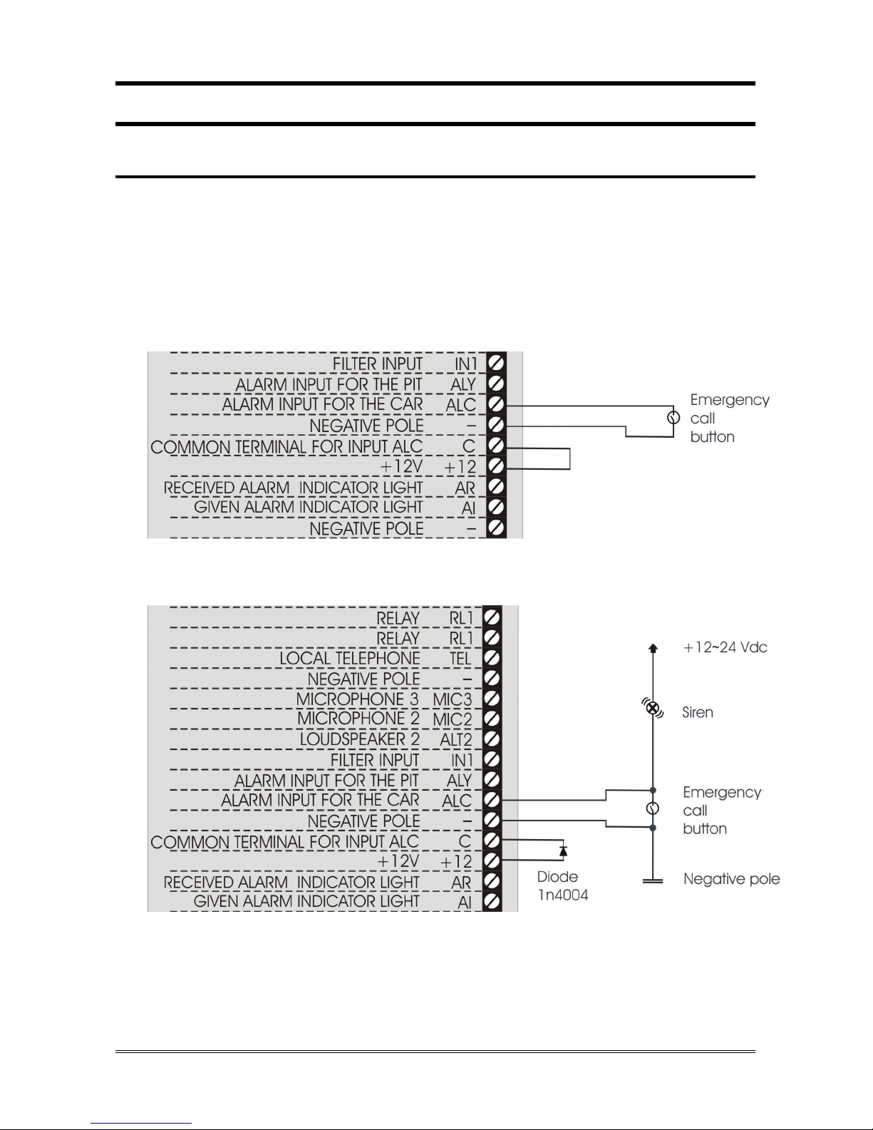
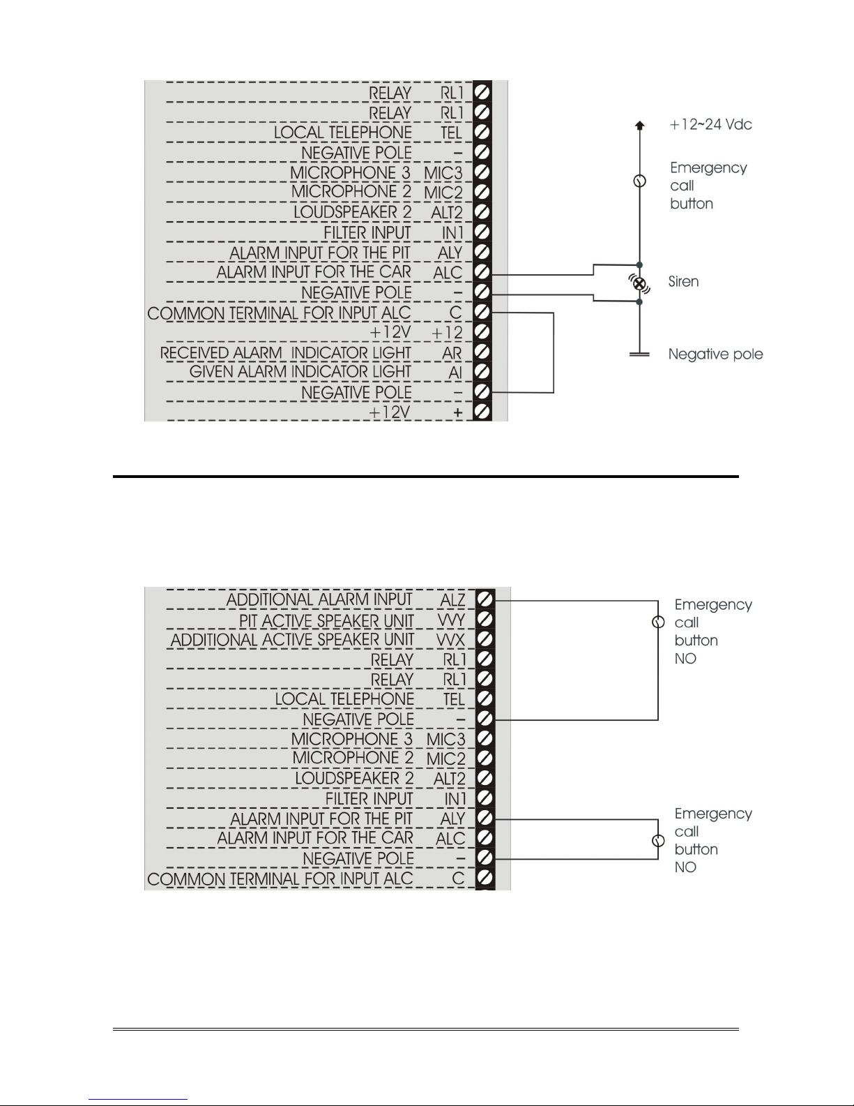
CONNECTING THE EMERGENCY CALL BUTTONS
Car pushbutton
It is possible to connect (inside the elevator car) voltage free contact
pushbuttons or powered pushbuttons.
Connect, following one of the diagrams shown below, the car
pushbutton.
Voltage free contact pushbuttons
Powered pushbuttons (12~24Vdc) – 2 solutions
INSTALLING Page 9
Other pushbuttons
It is possible to use for the pit, the car-top or the landing floors, voltage free
contact pushbuttons (NO).
Connect, following the diagram shown below, the other pushbuttons.
Page 10 INSTALLING
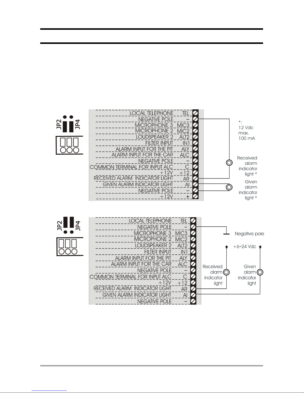
CONNECTING THE INDICATOR LIGHTS
The GIVEN ALARM INDICATOR LIGHT (yellow) switches on after pressing
the emergency button to indicate the beginning of the alarm procedure and
stays steady light until the end. The RECEIVED ALARM INDICATOR
LIGHT (green) switches on when the alarm call is answered.
Connect, following one of the diagrams shown below, the indicator
lights.
 Loading...