

Esse-ti HELPY 2W-TL Quick Manual

15/01/2019
Alarm system for elevators
compliant with the European Standard
EN 81-28:2018
HELPY 2W-TL
QUICK GUIDE
Page 2 DESCRIPTION
DESCRIPTION
Autodialer specifically designed for installation on car roof.
Versions:
Helpy 2W-TL comes with power supply and backup battery
Helpy 2W-TL 12 V 12 V power supply
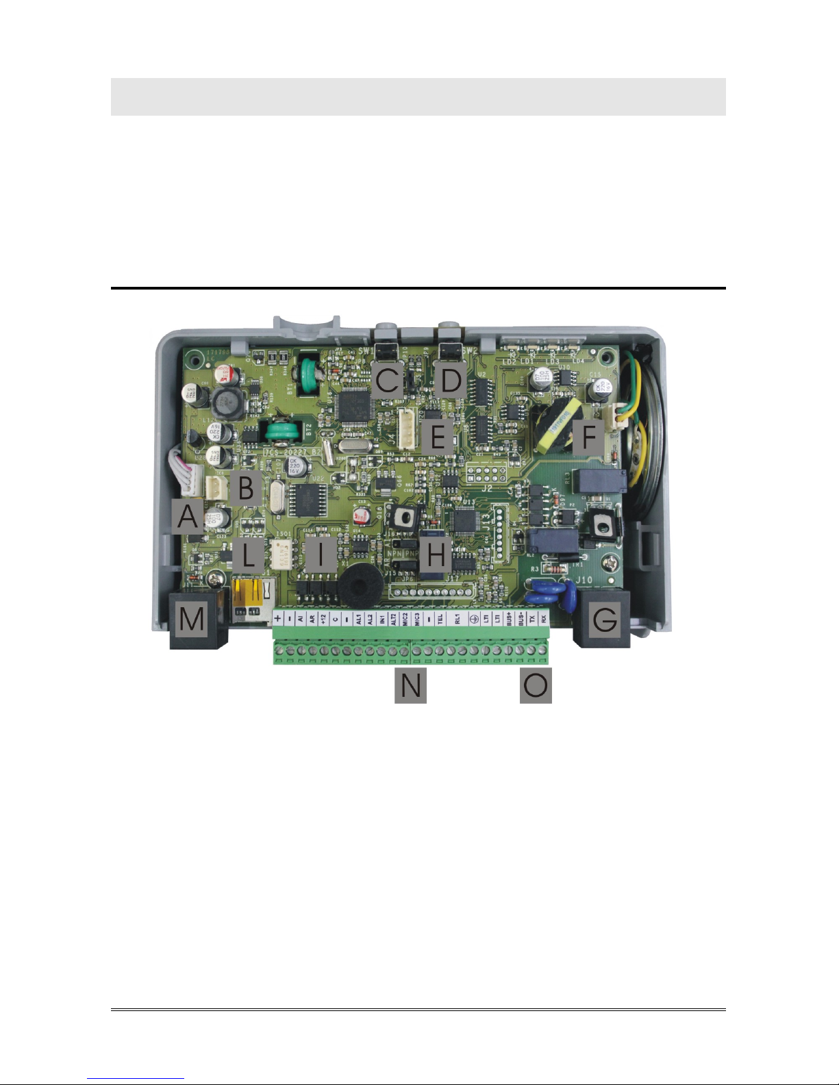
Helpy 2W-TL
A Internal power-supply connector
B Built-in backup battery connector
C Reset pushbutton
D Alarm pushbutton
E Serial port for PC connection
F Built-in loudspeaker connector
G RJ11 connector for local telephone
H Jumper J16 for define the behaviour of output AI
Jumper J15 for define the behaviour of output AR
I Built-in microphone
DESCRIPTION Page 3
L Micro SD card slot
M RJ45 connector for GSM200-C module
N Terminal blocks
O Battery compartment door
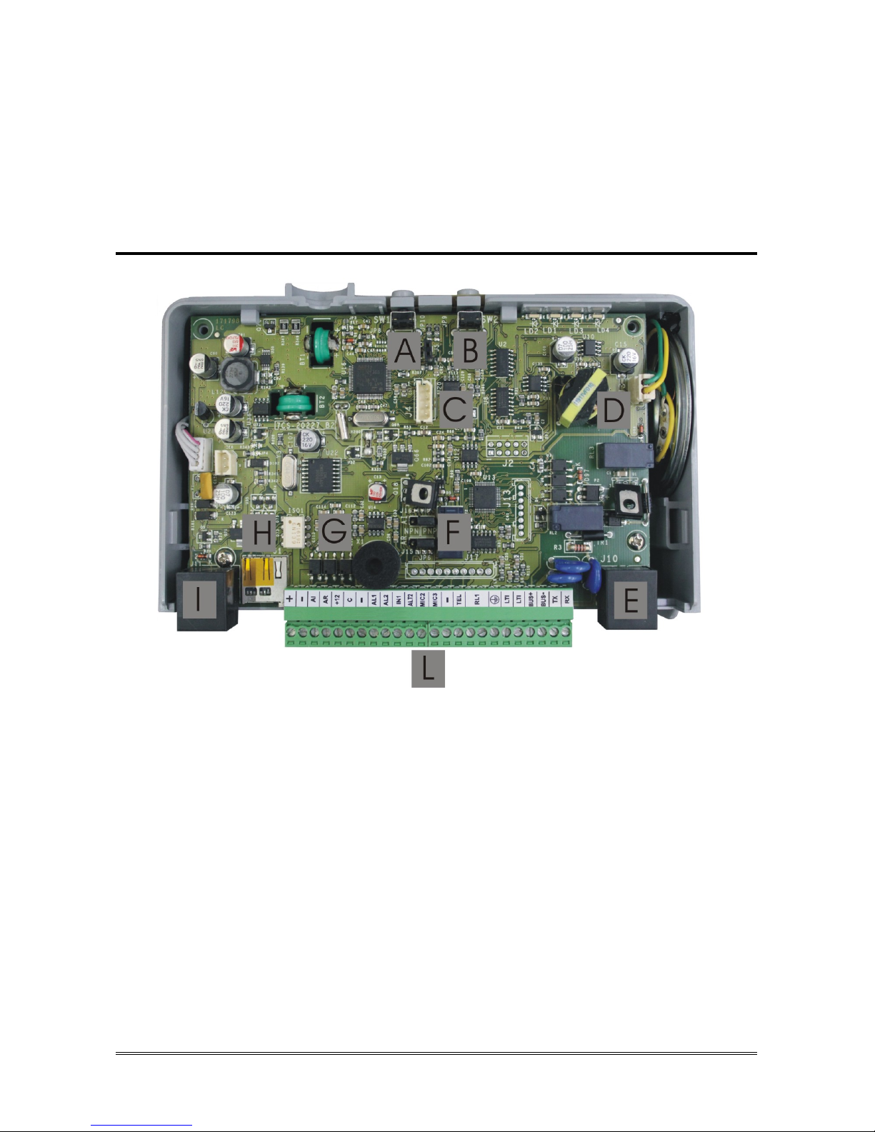
Helpy 2W-TL 12 V
A Reset pushbutton
B Alarm pushbutton
C Serial port for PC connection
D Built-in loudspeaker connector
E RJ11 connector for local telephone
F Jumper J16 for define the behaviour of output AI
Jumper J15 for define the behaviour of output AR
G Built-in microphone
H Micro SD card slot
I RJ45 connector for GSM200-C module
L Terminal blocks

Page 4 DESCRIPTION
LEDs
LED signalling alarm / periodical test call (yellow)
LED signalling GSM200-C signal strength (green)
LED signalling device status (red)
LED signalling power supply status (blue)
Terminal blocks
+ 12 Vdc power supply input
(1)
(14,5 Vdc power supply input if battery present)
- Negative pole
AI Given alarm indicator light
(NPN/PNP by means of J16)
AR Received alarm indicator light
(NPN/PNP by means of J15)
+12 12 Vdc output max. 100 mA
C Common terminal
(2)
for input AL1 and IN1
- Negative pole
AL1 Alarm input
(3)
1
AL2 Alarm input
(4)
2 / Auxiliary input
(4)
/ Reset input
(4)
IN1 Alarm 1 filter input
(3)
/ Reset input
(4)
ALT2 Output for connecting the loudspeaker of passive speaker units
MIC2 Input for connecting the microphone of a passive speaker unit or a
single microphone
MIC3 Input for connecting the microphone of a passive speaker unit or a
single microphone
- Negative pole
TEL Local telephone
RL1 Relay
(5)
RL1 Relay
(5)
Ground terminal for PSTN-line
LTI PSTN-line or universal GSM gateway input
LTI PSTN-line or universal GSM gateway input
BUS+ Bus for connecting 2W speaker units
BUS
- Bus for connecting 2W speaker units
TX TX for serial connection to elevator CPU
(RS-232)
RX RX for serial connection to elevator CPU
(RS-232)

DESCRIPTION Page 5
(1)
: before using this input disconnect the internal power-supply cable, if present, from the A
connector in the picture at page 2
(2)
: can be connected to a block –, to the block +12 or to an external reference
(3)
: allows to connect voltage free contact pushbuttons (NO or NC) or powered pushbuttons
(4)
: allows to connect voltage free contacts (NO or NC)
(5)
: free contact NO

Page 6 CONNECTING THE TELEPHONE LINE
CONNECTING THE TELEPHONE LINE
PSTN line or universal GSM gateway
Connect the ground terminal (indicated by ), to a ground socket in
order to increase the telephone line protection.
Connect the telephone line to terminal LTI.
GSM200-C module
Please see also the GSM200-C User Manual.
Connect the RJ45 connector (M in the picture at page 2 / I in the picture
at page 3) to the GSM200-C module by means of the supplied cable.

CONNECTING THE SPEAKER UNITS Page 7
CONNECTING THE SPEAKER UNITS
Helpy 2W-TL comes with a built-in speaker unit.
It is also possible to connect to the Helpy 2W-TL:
- up to 16 independent 2W speaker units by means of the 2-wire bus (4
units with direct power supply from the bus and 12 with separate power
supply)
- up to 2 passive speaker units (or cables with microphone) combined to the
built-in speaker unit.
Note:
a 2W speaker unit allows to realize an independent voice
point with dedicated pushbutton and indicator lights.
Note:
a passive speaker unit must be connected to the Helpy 2W-
TL’s built-in speaker unit or to another 2W speaker unit and
allows to double it. The passive speaker unit can be installed
at max. 6 m distance from Helpy 2W-TL (or from 2W speaker
unit) by using a shielded cable.
Each 2W speaker unit connected over the bus (the built-in speaker unit is
included) must have a unique ID. Speaker units with the same ID can not have
access to the bus and are not working.
Note:
the identifier 01 must be assigned to the cabin speaker unit
(default is assigned to the Helpy 2W-TL built-in speaker unit).
If the 01 ID is assigned to a 2W speaker unit, the built-in
speaker unit automatically takes the ID 99 (it is possible to
assign a new ID to the built-in speaker unit through the code
73).
Assign, using the DIP switch, an ID to each 2W speaker unit (see next
paragraph).
Connect the speaker units (beware of terminal polarity):
2W SPEAKER UNIT HELPY 2W-TL
BUS+ BUS+
BUS– BUS–
PASSIVE SPEAKER UNIT HELPY 2W-TL
A ALT2
B MIC2 or MIC3
– –
Page 8 CONNECTING THE SPEAKER UNITS
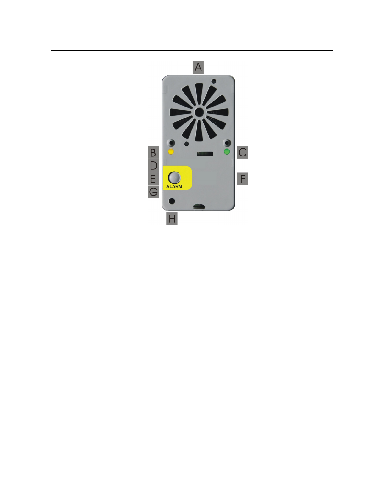
2W speaker unit description
A Loudspeaker
B Given alarm indicator light *
C Received alarm indicator light *
D DIP switch for ID assignation
E Pushbutton *
F Terminal blocks:
+12 Power supply input 12 Vdc
—
Negative
AR+
Received alarm indicator light (light positive pole)
AI+ Given alarm indicator light (light positive pole)
AR—
Received alarm indicator light (light negative pole)
AI—
Given alarm indicator light (light negative pole)
AL1—
Alarm input
AUX
Auxiliary input / Alarm input / Filter input
AL1+ Alarm input
BUS —
Bus for connecting Helpy 2W-TL
BUS +
Bus for connecting Helpy 2W-TL
* only for some models

CONNECTING THE SPEAKER UNITS Page 9
G Terminal blocks for connecting a passive speaker unit
ALT2
Output for connecting the loudspeaker of a passive
speaker unit
MIC2
Input for connecting the microphone of a passive
speaker unit or a single microphone
—
Negative
H Microphone
DIP switch
The DIP switch allows to assign an ID (01~16) to each 2W speaker unit
connected to the bus.
Note: it is possible to verify the operating devices over the bus
through the code 63.
ID: 01 (CAR) ID: 02 (PIT) ID: 03 (ROOF) ID: 04
ID: 05 ID: 06 ID: 07 ID: 08
ID: 09 ID: 10 ID: 11 ID: 12
ID: 13 ID: 14 ID: 15 ID: 16
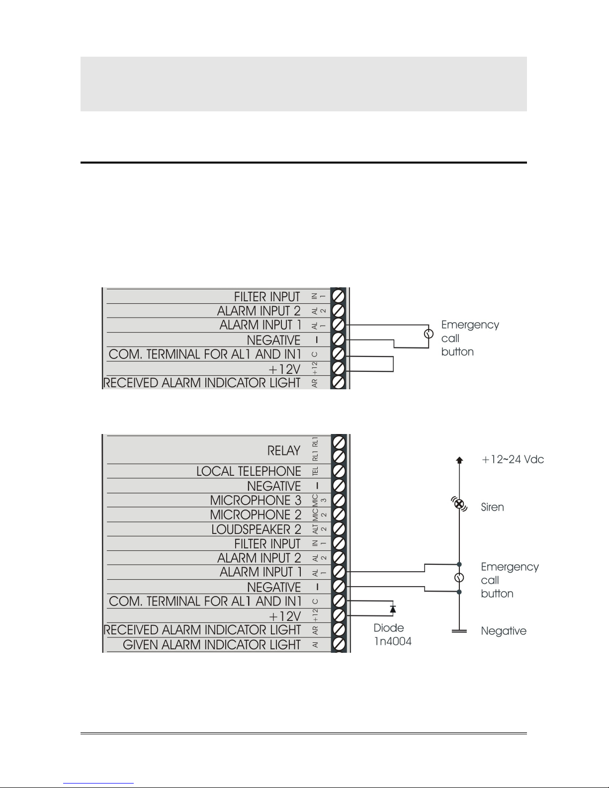
Page 10 CONNECTING THE EMERGENCY CALL BUTTONS
CONNECTING THE EMERGENCY
CALL BUTTONS
Car pushbutton
It is possible to connect (inside the elevator car) voltage free contact
pushbuttons or powered pushbuttons.
Connect, following one of the diagrams shown below, the car
pushbutton.
Voltage free contact pushbuttons
Powered pushbuttons (12~24Vdc) – 2 solutions
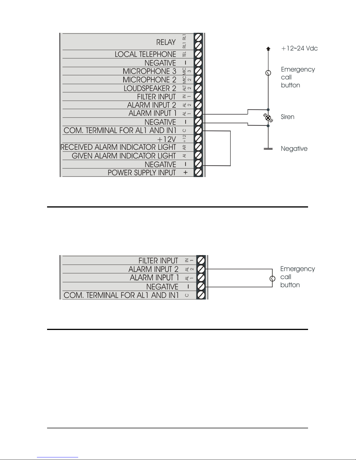
CONNECTING THE EMERGENCY CALL BUTTONS Page 11
Passive speaker unit pushbuttons
In case of passive speaker units without built-in pushbutton it is possible to use
voltage free contact pushbuttons (NO or NC).
Connect, following the diagram shown below, the external pushbutton.
2W speaker unit pushbuttons
It is possible to connect external pushbuttons (voltage free contact pushbuttons
or powered pushbuttons) to 2W speaker units without built-in pushbutton.
Connect, following one of the diagrams shown below, the external
pushbutton to the 2W speaker unit.
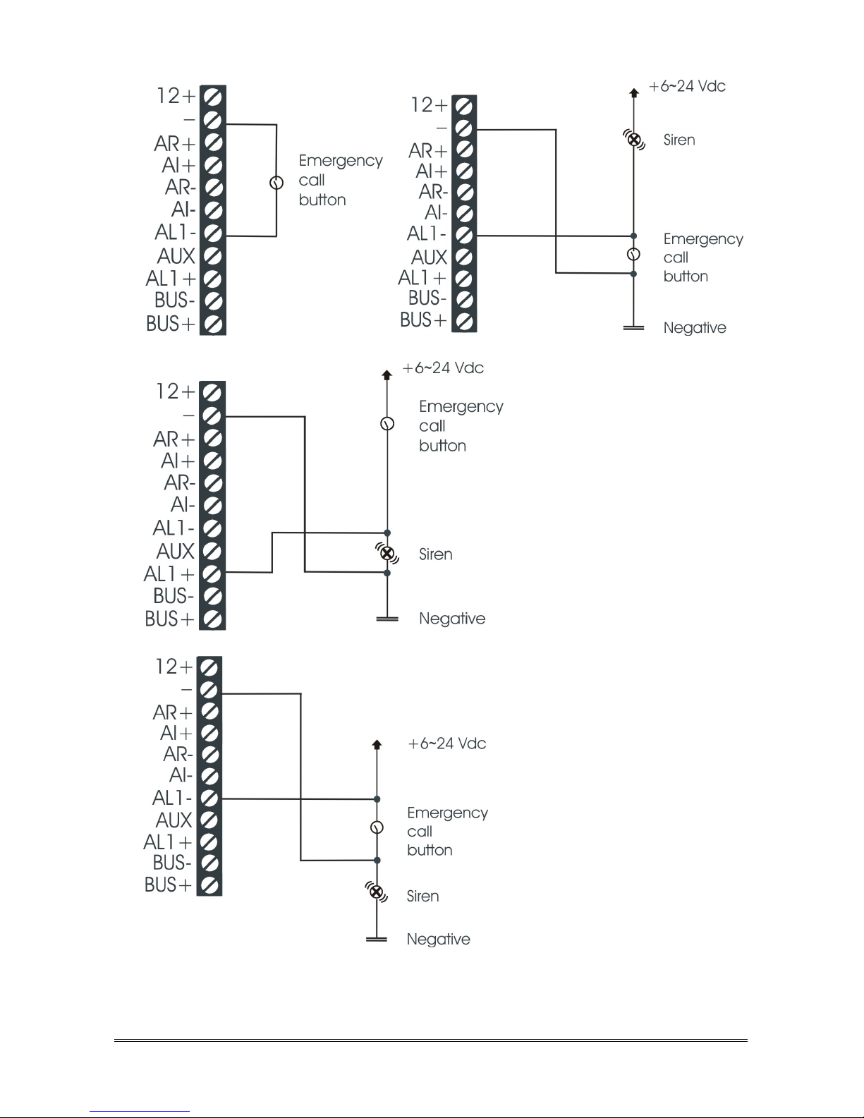
Page 12 CONNECTING THE EMERGENCY CALL BUTTONS
(this solution is allowed only if the
negative pole of Helpy 2W-TL is
not connected to the negative pole
of the lift)
 Loading...