

Page 1

05/04/2019
Alarm system for elevators
compliant with the European Standard
EN 81-28:2018
HELPY CONTROLLER
QUICK GUIDE
Page 2

Page 2 DESCRIPTION
DESCRIPTION
Autodialer specifically designed for installation on elevator controller.
A Connectors for optional PSTN-line board
B LEDs
C Reset pushbutton
D Micro USB A/B port for PC connection
E Serial port for PC connection
F RJ45 connector for GSM Satellite
G Terminal blocks
H Connector for machine room speaker unit
I 12 V backup battery connector
Page 3

TERMINAL BLOCKS Page 3
TERMINAL BLOCKS
+ 12 V In Power supply input 12 Vdc
- Negative
+ 12 V Out 12 Vdc output (max. 400 mA)
- Negative
TEL Local telephone
TEL Local telephone
BUS+ Bus for connecting 2W
speaker units
BUS- Bus for connecting 2W speaker units
C Common terminal
(1)
for input IN1
IN1 Filter input
(2)
/ Reset input
(2)
- Negative
(1)
: can be connected to a block –, to the block +12 V Out or to an external reference
(2)
: allows to connect voltage free contact (NO or NC) or powered contacts
Optional PSTN-line board
LTI PSTN-line or universal GSM gateway input
Ground terminal
LED
HELPY CONTROLLER
RED LED signalling device status
GREEN LED signalling GSM Satellite signal strength
WHITE LED signalling data transmission
YELLOW LED signalling alarm / periodical test call
BLU LED signalling power supply status
GSM SATELLITE
RED LED signalling GSM status
GREEN LED signalling GSM signal strength
Page 4

Page 4 CONNECTING THE TELEPHONE LINE
CONNECTING THE TELEPHONE LINE
The alarm system is ready for connection over the GSM line by the proprietary
GSM Satellite. It allows the connection of a PSTN line or an universal GSM
gateway with the optional PSTN-line board.
GSM Satellite
Installing the antenna and inserting the GSM SIM card in the
GSM satellite
Before proceeding, make sure the device is off and use all due precaution to
avoid electrostatic discharge.
Remove the GSM satellite cover.
Screw the antenna in the appropriate connector (take care to only rotate
the metal ferrule to fix the antenna; do not rotate the antenna on itself).
Push the SIM Card housing cover as indicated by the arrow OPEN until it
unlocks and lift it.
Carefully slide the SIM Card into its housing cover.
Lower the SIM Card housing cover and push it as indicated by the arrow
LOCK until it locks in place.
Close the GSM satellite cover.
ATTENTION
A GSM SIM card is required.
Do not use 3G/UMTS or 4G/LTE SIM cards.
ATTENTION
It is not required to remove the PIN code prior to
the use of the Helpy Controller.
The PIN code can be entered, if necessary, by
setting parameter 282.
ATTENTION
In order to avoid damage, never power up the
device without having first installed the antenna.
Page 5

CONNECTING THE TELEPHONE LINE Page 5
Connecting the GSM satellite
Connect the RJ45 connector of the GSM satellite to the RJ45 connector
of the Helpy Controller by means of the supplied cable.
PSTN line or universal GSM gateway
Insert the optional PSTN-line board in the dedicated connectors (A in the
picture at page 2)
Connect the ground terminal (indicated by
), to a ground socket in
order to increase the telephone line protection.
Connect the PSTN line or the universal GSM gateway to terminal LTI.
Page 6

Page 6 CONNECTING THE SPEAKER UNITS
CONNECTING THE SPEAKER UNITS
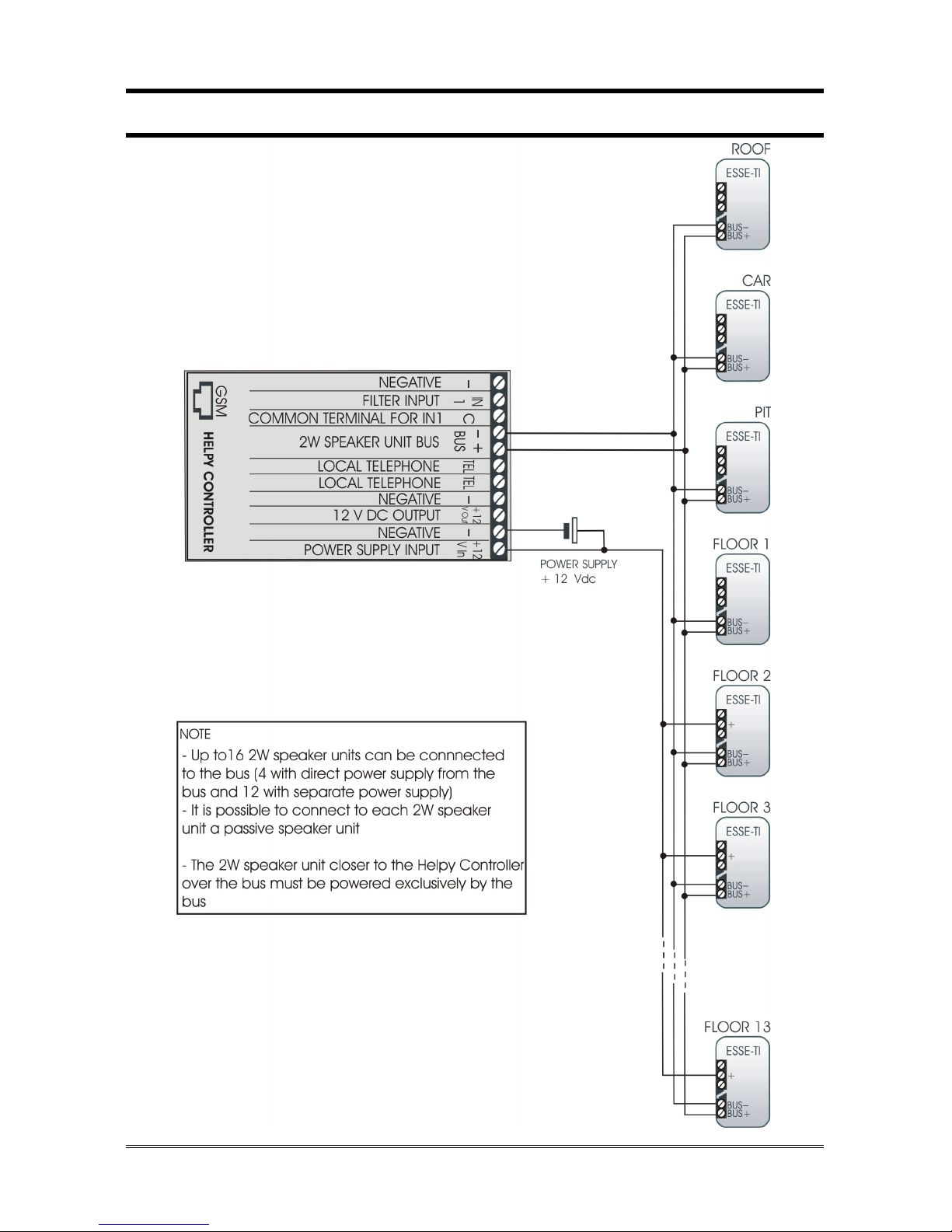
It is possible to connect to the Helpy Controller up to 16 independent 2W
speaker units by means of the 2-wire bus (4 units with direct power supply
from the bus and 12 with separate power supply).
Note:
a 2W speaker unit allows to realize an independent voice
point with dedicated pushbutton and indicator lights.
Note:
a passive speaker unit can be connected to each 2W speaker
unit and allows to double it. The passive speaker unit can be
installed at max. 6 m distance from 2W speaker unit by using
a shielded cable.
Each 2W speaker unit connected over the bus must have a unique ID. Speaker
units with the same ID cannot have access to the bus and are not working.
Note:
the identifier 01 must be assigned to the cabin speaker unit.
Assign, using the DIP switch, an ID to each 2W speaker unit (see next
paragraph).
Connect the speaker units (beware of terminal polarity):
2W SPEAKER UNIT HELPY CONTROLLER
BUS+ BUS+
BUS– BUS–
Page 7

CONNECTING THE SPEAKER UNITS Page 7
2W speaker unit description
A Loudspeaker
B Given alarm indicator light *
C Received alarm indicator light *
D DIP switch for ID assignation
E Pushbutton *
F Terminal blocks:
+12 Power supply input 12 Vdc
—
Negative
AR+
Received alarm indicator light (light positive pole)
AI+ Given alarm indicator light (light positive pole)
AR—
Received alarm indicator light (light negative pole)
AI—
Given alarm indicator light (light negative pole)
AL1—
Alarm input
AUX
Auxiliary input / Alarm input / Filter input
AL1+ Alarm input
BUS—
Bus for connecting Helpy Controller
BUS+
Bus for connecting Helpy Controller
* only for some models
Page 8
Page 8 CONNECTING THE SPEAKER UNITS
G Terminal blocks for connecting passive speaker unit
ALT2
Output for connecting loudspeaker of passive speaker
unit
MIC2
Input for connecting microphone of passive speaker
unit or single microphone
—
Negative
H Microphone
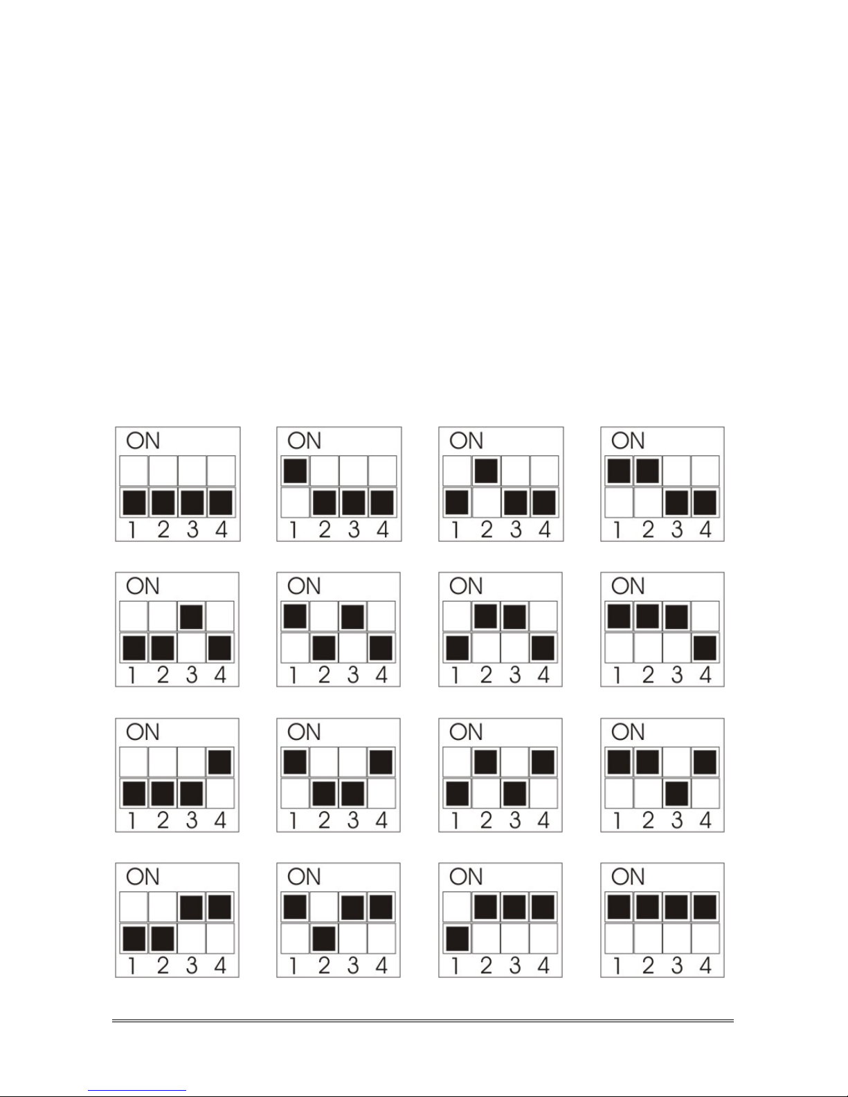
DIP switch
The DIP switch allows to assign an ID (01~16) to each 2W speaker unit
connected to the bus.
Note: it is possible to verify the operating devices over the bus
through the code 63.
ID: 01 (CAR) ID: 02 (PIT) ID: 03 (ROOF) ID: 04
ID: 05 ID: 06 ID: 07 ID: 08
ID: 09 ID: 10 ID: 11 ID: 12
ID: 13 ID: 14 ID: 15 ID: 16
Page 9
CONNECTING THE EMERGENCY CALL BUTTONS Page 9
CONNECTING THE EMERGENCY
CALL BUTTONS
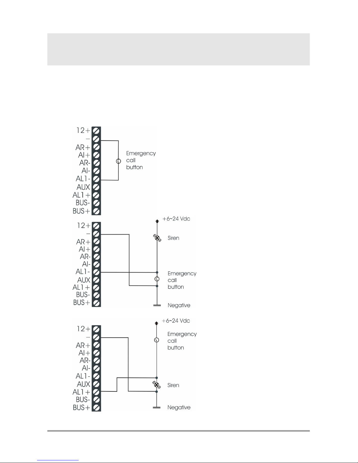
It is possible to connect external pushbuttons (voltage free contact pushbuttons
or powered pushbuttons) to 2W speaker units without built-in pushbutton.
Connect, following one of the diagrams shown below, the external
pushbutton to the 2W speaker unit.
Page 10

Page 10 CONNECTING THE INDICATOR LIGHTS
CONNECTING THE INDICATOR
LIGHTS
The GIVEN ALARM INDICATOR LIGHT (yellow) switches on after pressing
the emergency button to indicate the beginning of the alarm procedure. The
RECEIVED ALARM INDICATOR LIGHT (green) switches on when the
alarm call is answered.
Some 2W speaker unit models come with built-in indicator lights. It is also
possible to connect external indicator lights.
Connect, following one of the diagrams shown below, the external
indicator lights to the 2W speaker unit.
Page 11

OTHER CONNECTIONS Page 11
OTHER CONNECTIONS
CONNECTING THE LOCAL TELEPHONE
Connect the local telephone (for programming and managing the
device) to TEL and – terminals (irrespective of the polarity).
CONNECTING THE FILTER INPUT
Connect the filter contact as per one of the modes shown in the table:
C TERMINAL
CONNECTED TO:
FILTER CONTACT
TERMINAL BLOCKS
+12 V Out IN1 / –
–
IN1 / +12 V Out
external reference IN1 / external reference
Note: if a 2W speaker unit is installed in the cabin, it is possible to
use the terminal block’s filter input of the speaker unit (AUX
and – terminal blocks).
CONNECTING THE AUXILIARY INPUT
2W speaker units come with an AUX input (configurable as auxiliary input,
alarm input or filter input).
Connect the external contact to AUX and – terminals.
Note: the AUX input can be configured either as normally open or
closed.
Page 12
Page 12 WIRING DIAGRAMS
WIRING DIAGRAMS
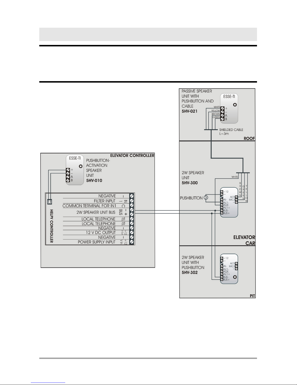
WIRING DIAGRAM WITH 2W SPEAKER UNITS IN THE
CAR AND IN THE PIT AND PASSIVE SPEAKER UNIT ON
CAR TOP
Page 13
WIRING DIAGRAMS Page 13
WIRING DIAGRAM WITH LANDING FLOORS
Page 14
Page 14 MINIMUM OPERATIONS TO VERIFY PROPER INSTALLATION
MINIMUM OPERATIONS TO VERIFY
PROPER INSTALLATION
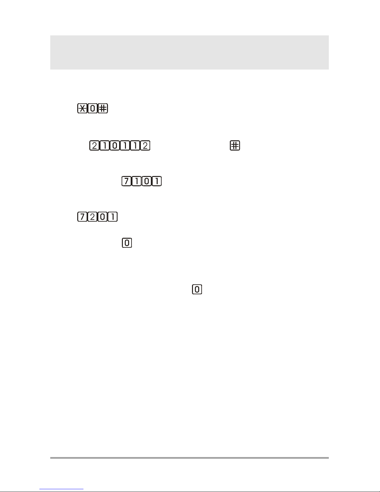
1. PROGRAMMING
Access to programming: lift the local telephone handset and dial
.
The programming activated message will be heard.
Program a telephone number for the emergency-call alarm:
dial
<telephone number> .
Record the identification message of the specific elevator, which is
meant to contain all necessary information concerning the elevator
location: dial
and, after the “Correct” message, pronounce
the message and hang up.
To listen again to the previous message: lift the handset and dial
.
Make an external call to check the GSM satellite module is properly
working: dial
and, after the “Correct” message, digit the telephone
number to make a test call.
or
Make an external call to check the PSTN line or the universal GSM
gateway is properly working: dial and digit the telephone number to
make a test call.
2. TESTING THE ALARM PROCEDURE
Press the emergency call button for more than 3 seconds (factory
value).
The alarm starts.
3. ANSWERING THE ALARM
Note: the activation mode of the communication with the trapped
person can be configured with the “Handsfree connection
mode during an alarm” programming (code 78).
-1
st
mode: automatic handsfree connection after the messages
(factory default)
Answer by the called party.
The handsfree mode will be activated after the voice messages.
Page 15

MINIMUM OPERATIONS TO VERIFY PROPER INSTALLATION Page 15
Speak with the trapped person.
-2nd mode: handsfree connection by “Handsfree activation” code
Answer by the called party.
The voice messages will be heard.
Press to speak with the trapped person.
-3nd mode: automatic handsfree connection without messages
Answer by the called party.
Speak with the trapped person.
4. RESETTING THE ALARM
Note: the alarm reset mode can be configured with the “Alarm reset
mode” programming (code 77).
-1
st
mode: reset by “End” code (factory default)
Press to end the alarm.
-2
nd
mode: automatic reset
Hang up (or press ) to end the alarm.
-3nd mode: automatic reset with local acknowledgement
Hang up to end the call.
Press the reset pushbutton or close the reset input IN1 to end the
alarm.
An end-of-alarm call will be generated.
Answer by the called party.
Press
.
If the reset input is not closed within 6 hours, the alarm is automatically ended.
Note:
the reset input can be configured with the “IN1 input setting”
programming (code 55).
Note: in case it should not be possible to stop the alarm procedure
remotely (i.e. the entered telephone number is incorrect)
simply lift the handset of the local telephone and dial
* <Password> # (by factory default:
) or press the
reset pushbutton.
Page 16

Page 16 MINIMUM OPERATIONS TO VERIFY PROPER INSTALLATION
USING THE RESET BUTTON
Note: the reset operation does not alter the previously set
parameters.
Use of the reset pushbutton (C in the picture at page 2):
- Pressing shortly
Allows to interrupt an alarm call.
By pressing shortly you get the same result as lifting the handset of the
local telephone and entering * <Password> #.
- Pressing longer (10 seconds)
Allows to reset the device.
By pressing longer, the Helpy Controller will be re-started with no need to
disconnect the power supply.
Note: it is also possible to reset the device through the code
995*0#.
Page 17
PROGRAMMING Page 17
PROGRAMMING
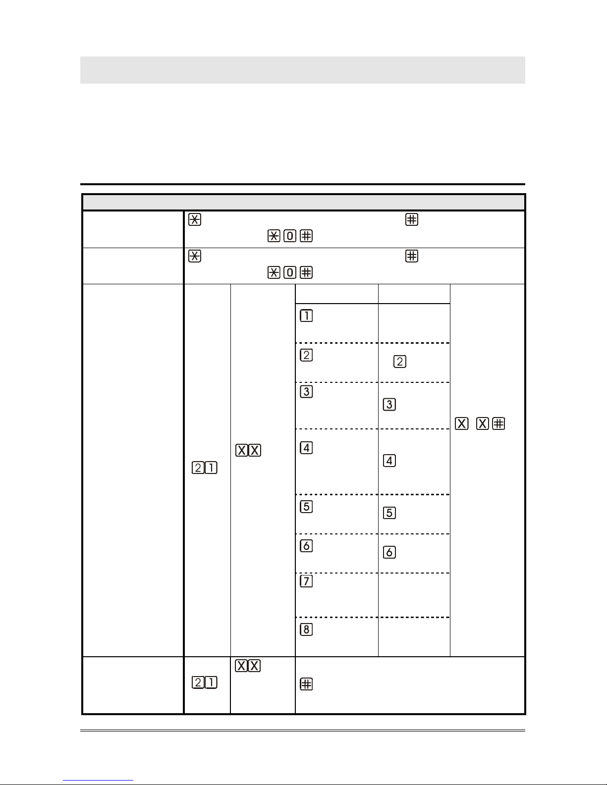
In the tables below:
INST indicates that the programming is allowed for the installer
OPER indicates that the programming is allowed by the maintenance technician
factory default values are highlighted in bold
Basic programming
BASIC PROGRAMMING
ACCESS TO
PROGRAMMING
< INSTALLER or OPERATOR PASSWORD >
(factory default:
)
EXITING THE
PROGRAMMING
< INSTALLER or OPERATOR PASSWORD >
(factory default:
)
TELEPHONE
NUMBERS
(INST)
* the programming
of the telephone
number
automatically
activates the
alarm/call
(position
from 01 to
12)
SOURCE RECEIVER
…
(X..X =
telephone
number,
max. 20
digits; * = 2
sec-pause)
emergency-
call button
-
battery
alarms *
USER
periodic
automatic test
call *
ESSE-TI
2W speaker
unit connection
failure alarm
CLI
SIM card
expiring alarm
SMS
diagnostic
alarm *
P100
no external
power supply
alarm
-
auxiliary
alarm
-
DELETE A
TELEPHONE
NUMBER
(INST)
(position
from 01 to
12)
Page 18
Page 18 PROGRAMMING
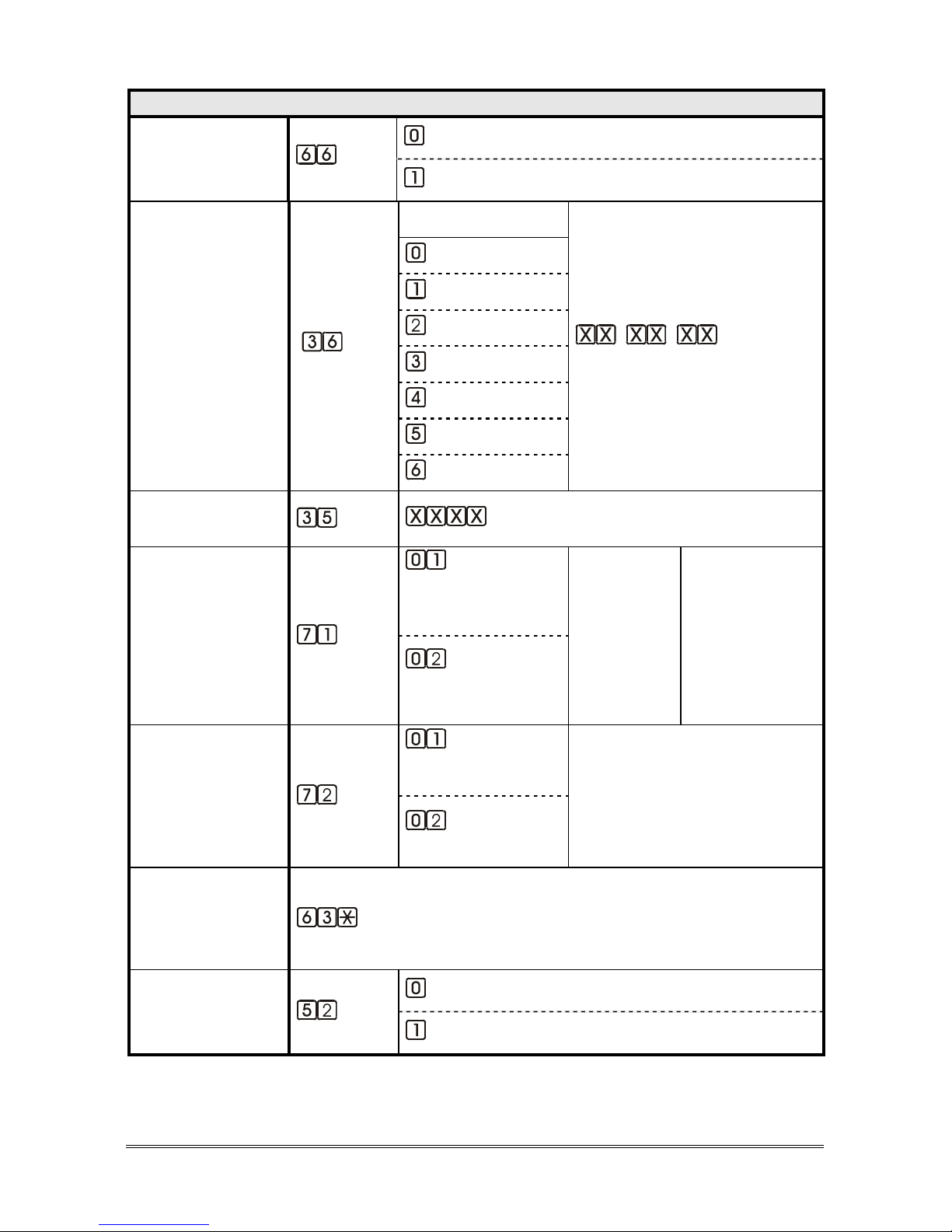
BASIC PROGRAMMING
TYPE OF
TELEPHONE LINE
(INST)
PSTN line or universal GSM gateway
GSM Satellite
DATE
(INST)
WEEKDAY
(dd) (mm) (yy)
SUNDAY
MONDAY
TUESDAY
WEDNESDAY
THURSDAY
FRIDAY
SATURDAY
TIME
(INST)
(hhmm; from 0000 to 2359)
RECORD
MESSAGES
(INST)
identification
message
(max. 25s )
(record) (hang up)
courtesy message
(max. 25 s)
LISTEN TO
MESSAGES
(INST/OPER)
identification
message
(listen)
courtesy message
LISTEN TO THE
ID DEVICES
OPERATING
OVER THE BUS
(INST)
LOW BATTERY
ALARM
(INST)
disabled alarm
enabled alarm
Page 19
PROGRAMMING Page 19
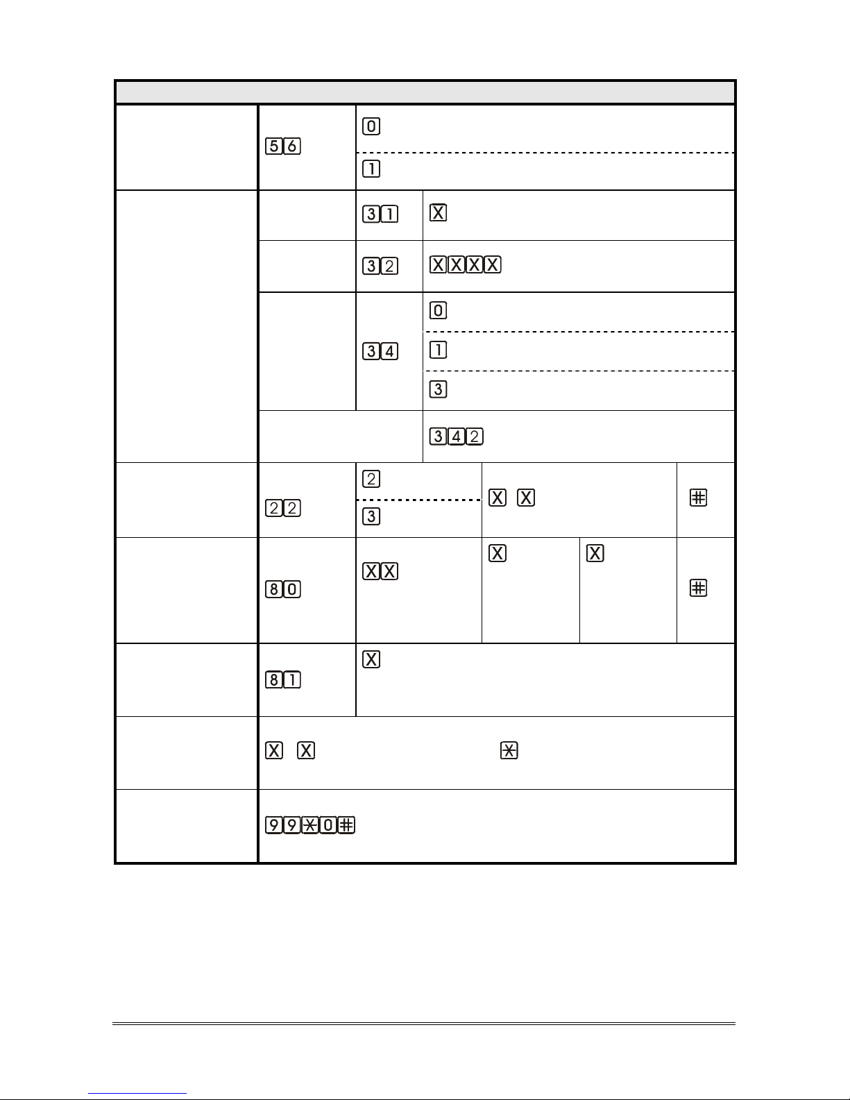
BASIC PROGRAMMING
REPLACE
BATTERY ALARM
(INST)
disabled alarm
enabled alarm
AUTOMATIC TEST
DATA
(INST)
Frequency
(days, from 1 to 9; factory default 3)
Time
(hhmm; from 0000 to 2359)
Automatic
test alarm
automatic test disabled
automatic test enabled (EN 81-28:2018)
automatic test enabled (EN 81-28:2004)
Make a test call
manually
PROTOCOLS
IDENTIFICATION
CODE
(INST)
Esse-ti
… (identification code) [ ]
P100
SPEAKER UNITS
VOLUME
(INST/OPER)
speaker unit ID
(from 01 to 16)
loudspeaker
(from 1 to
9; factory
default 3)
microphone
(from 1 to
9; factory
default 5)
[
]
VOLUME OF
LANDING FLOOR
MESSAGES
(INST/OPER)
(from 1 to 4; factory default 3; 4=loudspeaker
volume, 3=¾ of loudspeaker volume, 2=½ of
loudspeaker volume, 1=¼ of loudspeaker volume)
LISTEN TO THE
PROGRAMMING
AGAIN
(INST)
... (programming code prefix)
RESTORE
FACTORY
SETTINGS
(INST)
Page 20
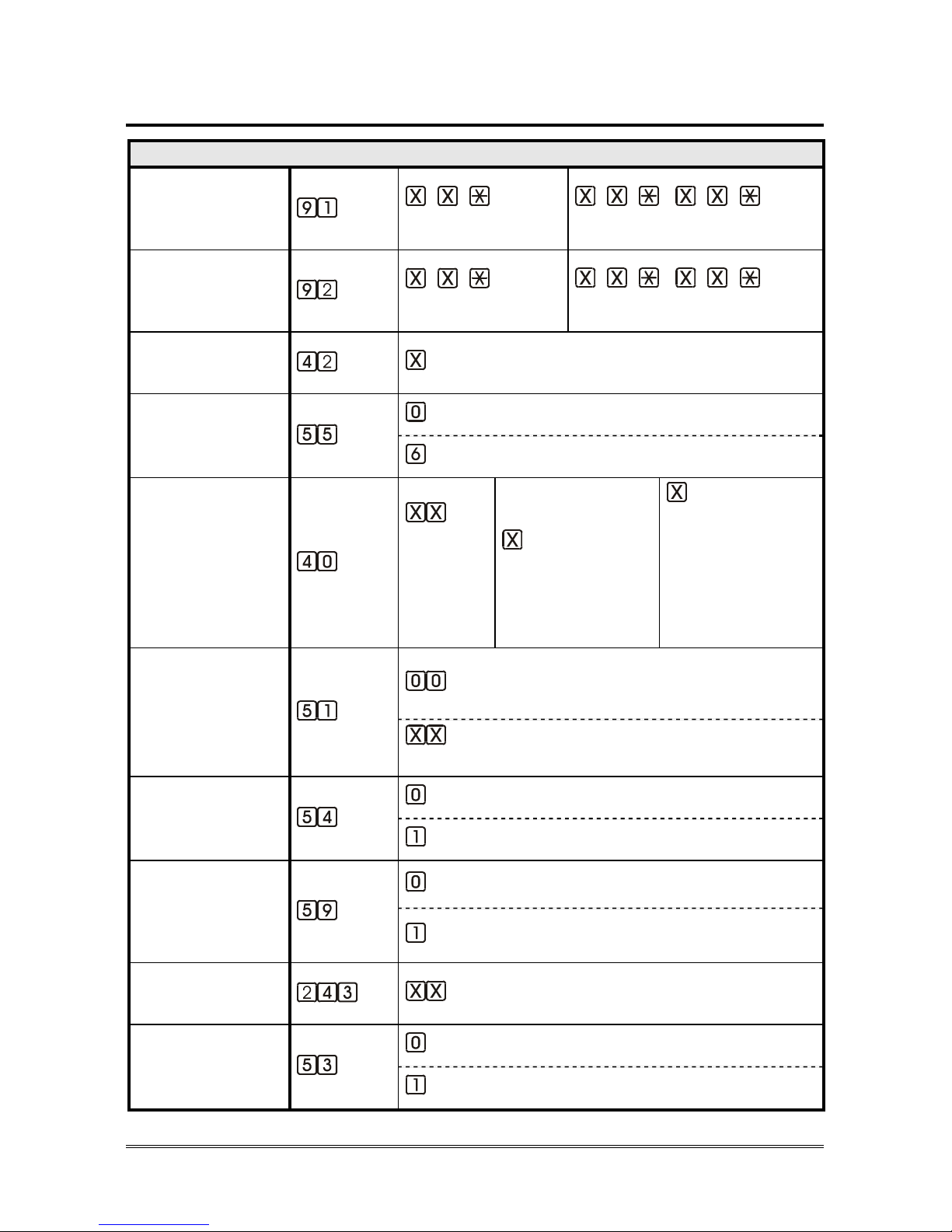
Page 20 PROGRAMMING
Advanced programming
ADVANCED PROGRAMMING
CHANGE THE
INSTALLER
PASSWORD “0”
(INST)
… [ ]
(old)
.. [ ] .. [ ]
(new) (new)
CHANGE THE
OPERATOR
PASSWORD “1”
(INST)
… [ ]
(old)
.. [ ] .. [ ]
(new) (new)
EMERGENCY CALL
BUTTONS DELAY
(INST)
(seconds, from 3 to 9)
IN1 INPUT
SETTING
(INST)
IN1 = filter
IN1 = reset
2W SPEAKER
UNIT INPUTS
SETTING
(INST)
speaker
unit ID
(from 01
to 16)
AL1
(0=normally closed
1=normally open)
AUX
(0=alarm NC
1=alarm NO
2=auxiliary NC
3=auxiliary NO
4=filter NC
5=filter NO)
NO EXTERNAL
POWER SUPPLY
ALARM
(INST)
disabled alarm
enabled alarm with XX minutes delay
(from 01 to 99)
DIAGNOSTIC
ALARM
(INST)
disabled alarm
enabled alarm
2W SPEAKER
UNIT
CONNECTION
FAILURE ALARM
(INST)
disabled alarm
enabled alarm
SIM CARD
EXPIRING ALARM
(INST)
(months, from 01 to 30; 00=disabled alarm)
FILTER
ACTIVATION
(INST/OPER)
disabled
enabled
Page 21
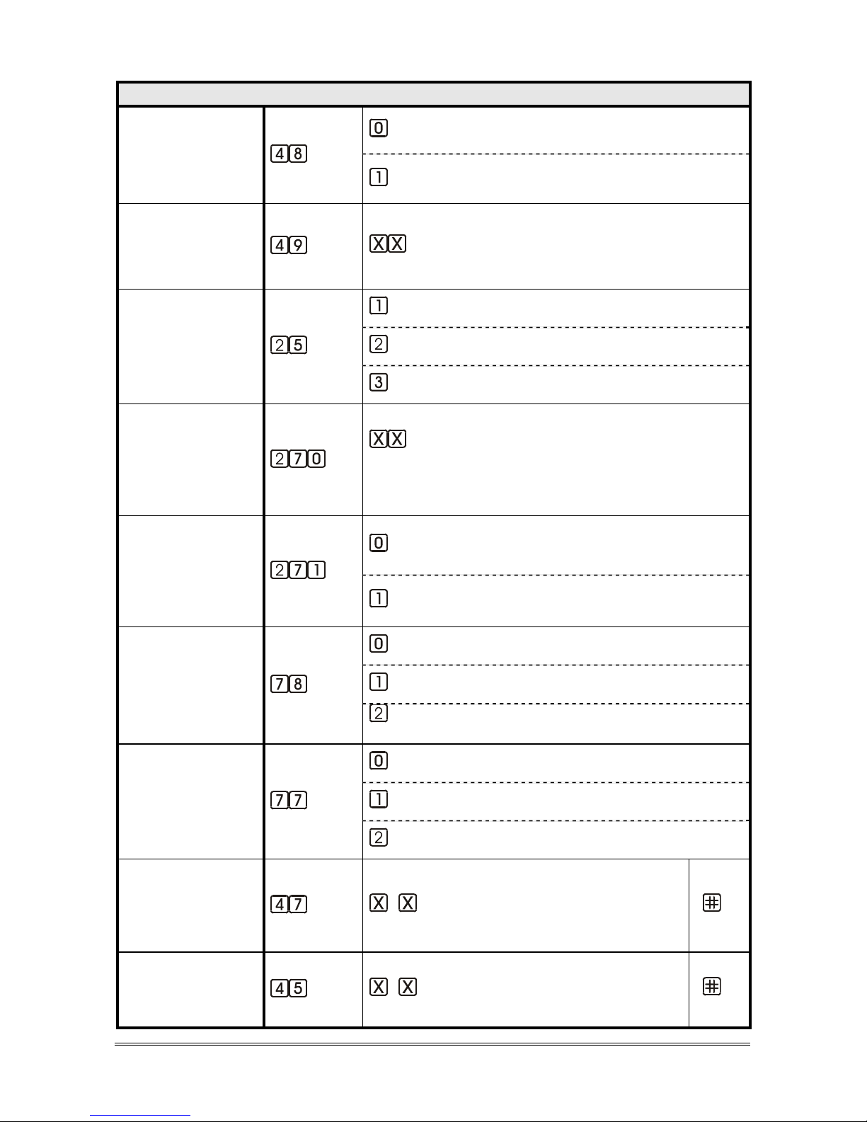
PROGRAMMING Page 21
ADVANCED PROGRAMMING
FILTER INPUT
NORMALLY
CLOSED/OPEN
(INST/OPER)
normally closed
normally open
FILTER BYPASS
(INST)
(seconds, from 15 to 30)
ALARM
OPERATION
WITHOUT
TELEPHONE LINE
(INST)
AI indicator light lit and courtesy message
AI indicator light unlit and no courtesy message
AI indicator light lit and no courtesy message
REPEATS OF
COURTESY
MESSAGE
DURING
AN ALARM
(INST)
(seconds between two courtesy messages, from
02 to 59; 00=no courtesy message; 01=one
courtesy message for each call)
“COMMUNICATION
ACTIVATED”
MESSAGE
SETTING
(INST)
disabled message
enabled message
HANDSFREE
CONNECTION
MODE DURING
AN ALARM
(INST)
handsfree activation by “Handsfree activation” code
automatic handsfree activation after messages
immediate and automatic handsfree activation
(no messages)
ALARM RESET
MODE
(INST)
automatic reset
alarm reset by “End alarm” code
automatic reset with local acknowledgement
“PLAY
IDENTIFICATION
MESSAGE”
CODE
(INST)
… (from 1 to 3 digits; factory default 5)
[ ]
“HANDSFREE
ACTIVATION”
CODE
(INST)
… (from 1 to 3 digits; factory default 0)
[ ]
Page 22
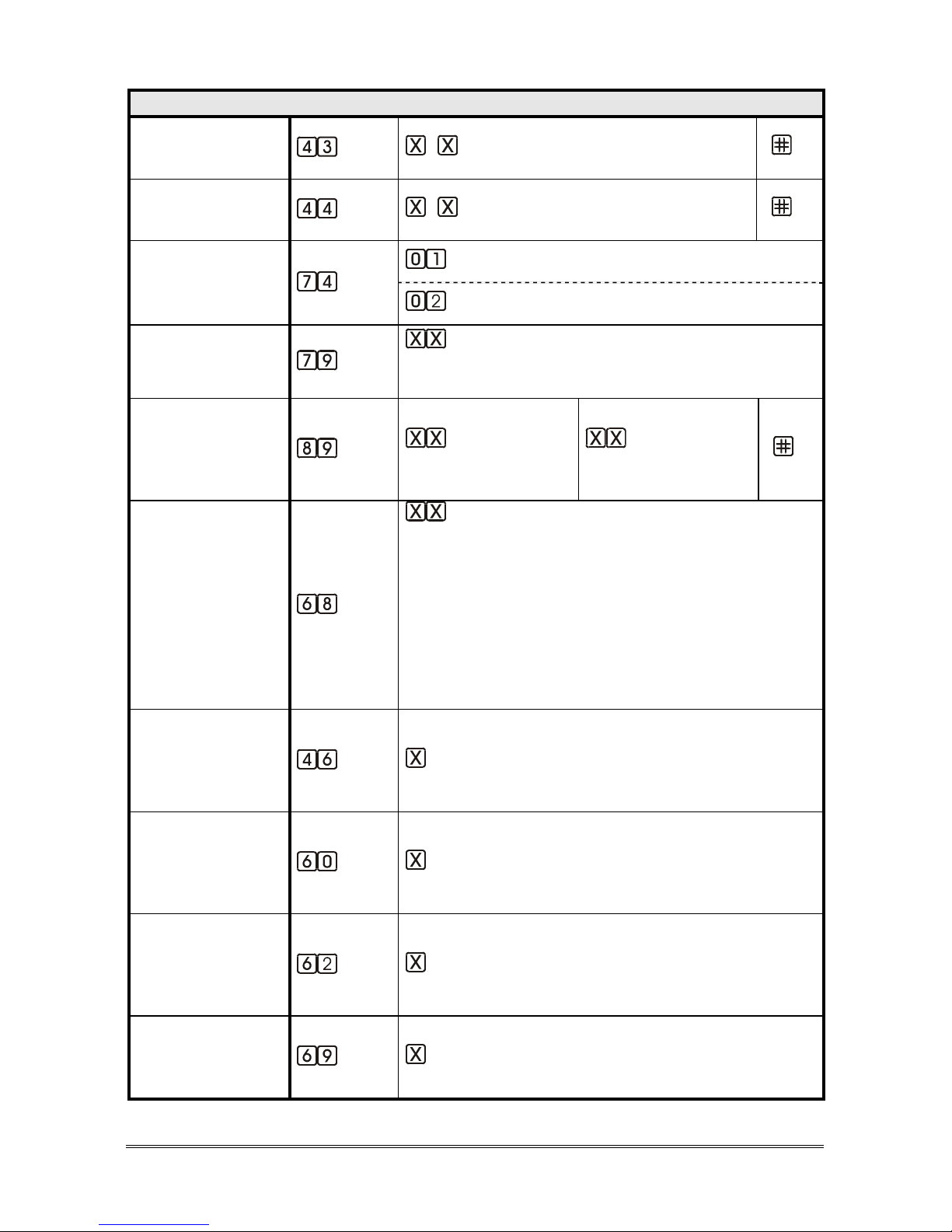
Page 22 PROGRAMMING
ADVANCED PROGRAMMING
“END ALARM”
CODE
(INST)
… (from 1 to 3 digits; factory default 9)
[ ]
“EXCLUSION”
CODE
(INST)
… (from 1 to 3 digits; factory default 1)
[ ]
RESTORE
FACTORY
MESSAGES
(INST)
identification message
courtesy message
LANGUAGE
(INST)
(language: 00 Italian, 01 English, 02 German,
03 French, 04 Polish, 06 Russian, 07 Spanish,
21 Flemish)
MULTILANGUAGE
COURTESY
MESSAGE
(INST)
(second language)
(third language)
[ ]
TONE DECODER
(INST)
(country: 00 IT/SM/AL/BA/GM/MK/MT/NO,
01 GB/AE, 02 DE/LB/LU, 03 FR/GP/GF, 04 PL,
05 PT, 06 RU/BY, 07 ES/AD/CY, 08 BG/BR/KY/
DK/ID/IR/IS/KW/MO/MW/MX/PY/UY/VE/YE/ZM/
FO/LR, 10 HR, 11 GR/EE/FI, 12 NL/AW/VU,
13 SI, 14 HU, 15 IL, 16 AT, 17 AU/IE, 18 CH,
19 CN, 20 US/CA/JM/AI/AG/BB/BM/VG/DM/MS/
KN/TT/TC 21 BE, 22 QA, 23 SE, 24 IN, 25 TR,
26 CZ/SK/LT/MD, 27 TN/SA, 28 DZ, 29 MA,
30 RS, 31 RO, 32 JO)
DURATION OF
HANDSFREE
CONNECTION
DURING ALARM
(INST)
(minutes, from 2 to 9)
NUMBER OF
CALLS TO THE
SAME NUMBER
FOR EACH CYCLE
(INST)
(calls, from 1 to 9)
CALL CYCLES FOR
TECHNOLOGICAL
ALARMS AND
TEST CALLS
(INST)
(cycles, from 1 to 9; 0=10 cycles; factory default 3)
CALL CYCLES FOR
EMERGENCY CALL
ALARMS
(INST)
(cycles, from 1 to 9; 0=unlimited)
Page 23
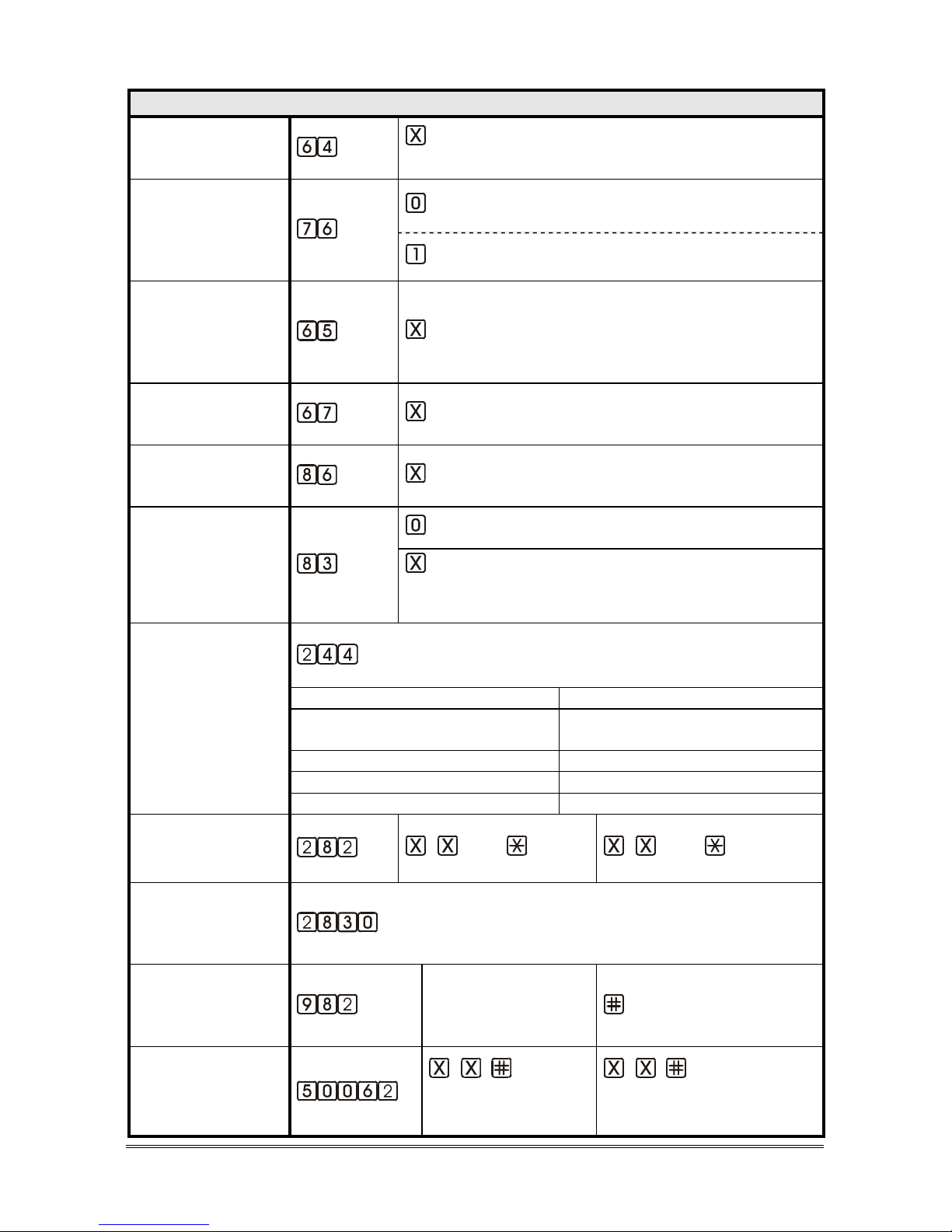
PROGRAMMING Page 23
ADVANCED PROGRAMMING
AUTOMATIC
ANSWER
(INST)
(ring number, from 1 to 9;
0=disabled; factory default 2)
OPERATION
MODE AFTER
AUTOMATIC
ANSWER
(INST)
programming mode
direct connection with the car
CONNECTION
DURATION AFTER
AUTOMATIC
RESPONSE
(INST)
(minutes, from 1 to 9)
CLI CALL
DURATION
(CLI)
(seconds, from 00 to 99; factory default 10)
MULTI-LINK
FUNCTION
(INST)
(from 0 to 9; 1=master, 0=function disabled)
DTMF
GENERATOR
SETTING
(INST)
DTMF generated by GSM network
DTMF generated by Helpy Controller
(DTMF duration=X*50ms; from 1 to 9;
factory default 2)
LISTEN TO THE
GSM SIGNAL
LEVEL
(INST)
Digits Quality
0-12 no signal or connection not
guaranteed
13-18 low signal
19-24 medium signal
>24 high signal
ENTER SIM CARD
PIN CODE
(INST)
… (PIN) … (PIN)
DISABLE SIM
CARD PIN
REQUEST
(INST)
GSM SATELLITE
APN SETTING
(only via SMS)
(INST)
APN[,user,pwd]
GSM SATELLITE
SIM NUMBER
SETTING
(INST)
…
(telephone number
with country code)
…
(telephone number with
country code)
Page 24
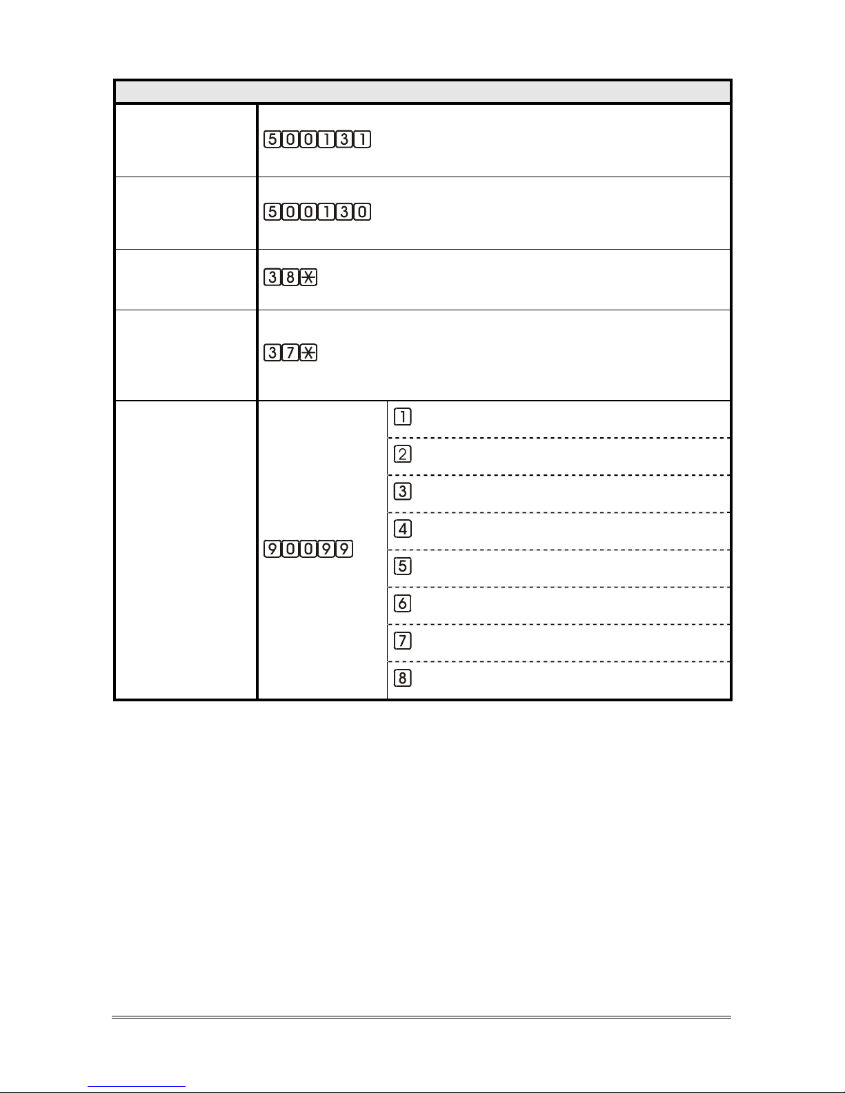
Page 24 PROGRAMMING
ADVANCED PROGRAMMING
REGISTER THE
GSM SATELITE TO
SERVER COMNET
(INST)
DELETE THE GSM
SATELLITE FROM
SERVER COMNET
(INST)
LISTEN TO THE
BATTERY LEVEL
(INST)
(expressed in mV)
LISTEN TO THE
EXTERNAL
POWER SUPPLY
LEVEL
(INST)
(expressed in mV)
TEST OF ALARMS
(INST)
emergency-call button
battery alarm
periodic automatic test call
2W speaker unit connection failure alarm
SIM card expiring alarm
diagnostic alarm
no external power supply alarm
auxiliary alarm
Page 25

PROGRAMMING Page 25
Programming via e-stant software
It is possible to program Helpy Controller via computer by using the
USB/serial proprietary cable and the dedicated e-stant software.
e-stant software also allows to:
- update the firmware of the Helpy Controller
- customize the messages of the Helpy Controller.
e-stant can be downloaded at the following link:
https://www.esse-ti.it/en/download/software-request
Page 26
Page 26 PROGRAMMING
Programming via SMS (only with GSM Satellite)
All parameters programmable locally by the local telephone may also be set via
SMS.
Programming via SMS is possible by any mobile phone or other device
supporting SMS.
An SMS notifying the programming was performed is sent by the Helpy
Controller to the number that sent the programming.
ATTENTION
Programmed performed via SMS sent from the Internet could not
have a positive result if the required format is not followed.
MESSAGE FORMAT
Each programming SMS must contain the password, which allows access to
programming, and the programming codes to be performed.
The message format must be as follows:
Et.he *xxx# c..c c..c
Where:
Et.he : is the start of the programming string
*xxx# : is the password string (default installer password xxx = 0)
c..c : is the programming code
The strings and programming codes must be separated by a space.
Refer to the related paragraphs for the programming codes.
NOTIFICATION MESSAGE FORMAT
The format of the notification message to the user who sent a programming
SMS is similar to the programming message:
Et!he *xxx# c..c c..cERROR
Where:
Et!he : is the start of the notification string
*xxx# : is the password string (default installer password xxx = 0)
c..c : is the accepted programming code
c..cERROR : is the refused programming code
Page 27
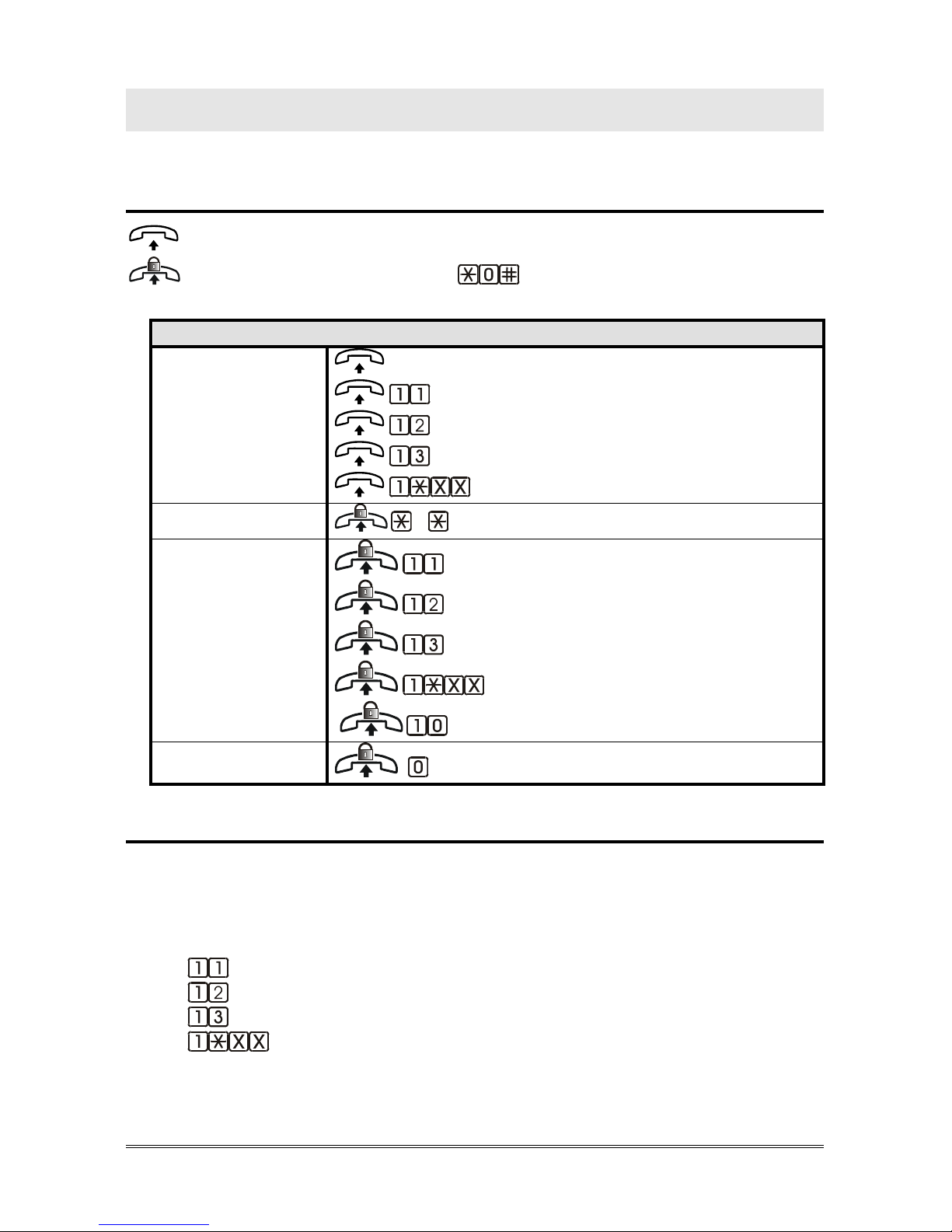
USE Page 27
USE
Local use
: lift the local telephone handset
: lift the local telephone handset and dial to access programming
LOCAL USE
CONVERSATION
WITH THE
SPEAKER UNITS
CABIN SPEAKER UNIT (ID 01)
CABIN SPEAKER UNIT (ID 01)
SPEAKER UNIT (ID 02)
SPEAKER UNIT (ID 03)
SPEAKER UNIT ID XX (04~16)
PROGRAMMING
…
CONVERSATION
WITH THE
SPEAKER UNITS
CABIN SPEAKER UNIT (ID 01)
SPEAKER UNIT (ID 02)
SPEAKER UNIT (ID 03)
SPEAKER UNIT ID XX (04~16)
DEACTIVATE ALL
EXTERNAL CALLS
<TELEPHONE NUMBER>
Use remotely with Helpy Controller at rest
Call Helpy Controller and wait for a response.
Listen to the elevator identification message, if present.
Dial:
to speak with the cabin speaker unit (ID 01)
to speak with the speaker unit (ID 02)
to speak with the speaker unit (ID 03)
to speak with the cabin speaker unit ID XX (04~16)
or
Page 28
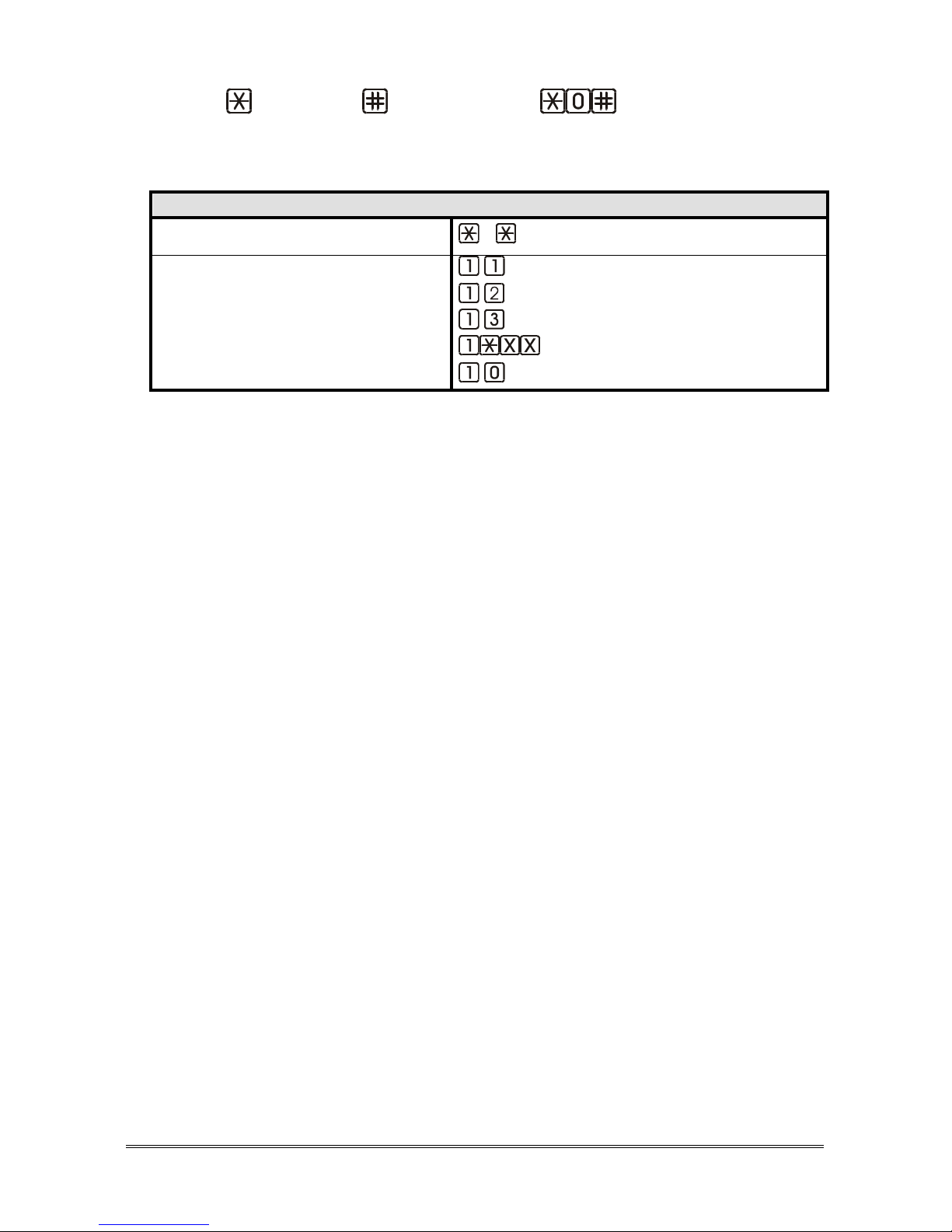
Page 28 USE
Dial <password> (factory default: ) to access
programming.
All of the programming and functions below can now be performed:
USE REMOTELY WITH HELPY CONTROLLER AT REST
PROGRAMMING
…
CONVERSATION
WITH THE SPEAKER UNITS
CABIN SPEAKER UNIT (ID 01)
SPEAKER UNIT (ID 02)
SPEAKER UNIT (ID 03)
SPEAKER UNIT ID XX (04~16)
DEACTIVATE ALL
Page 29
SIGNALS Page 29
SIGNALS
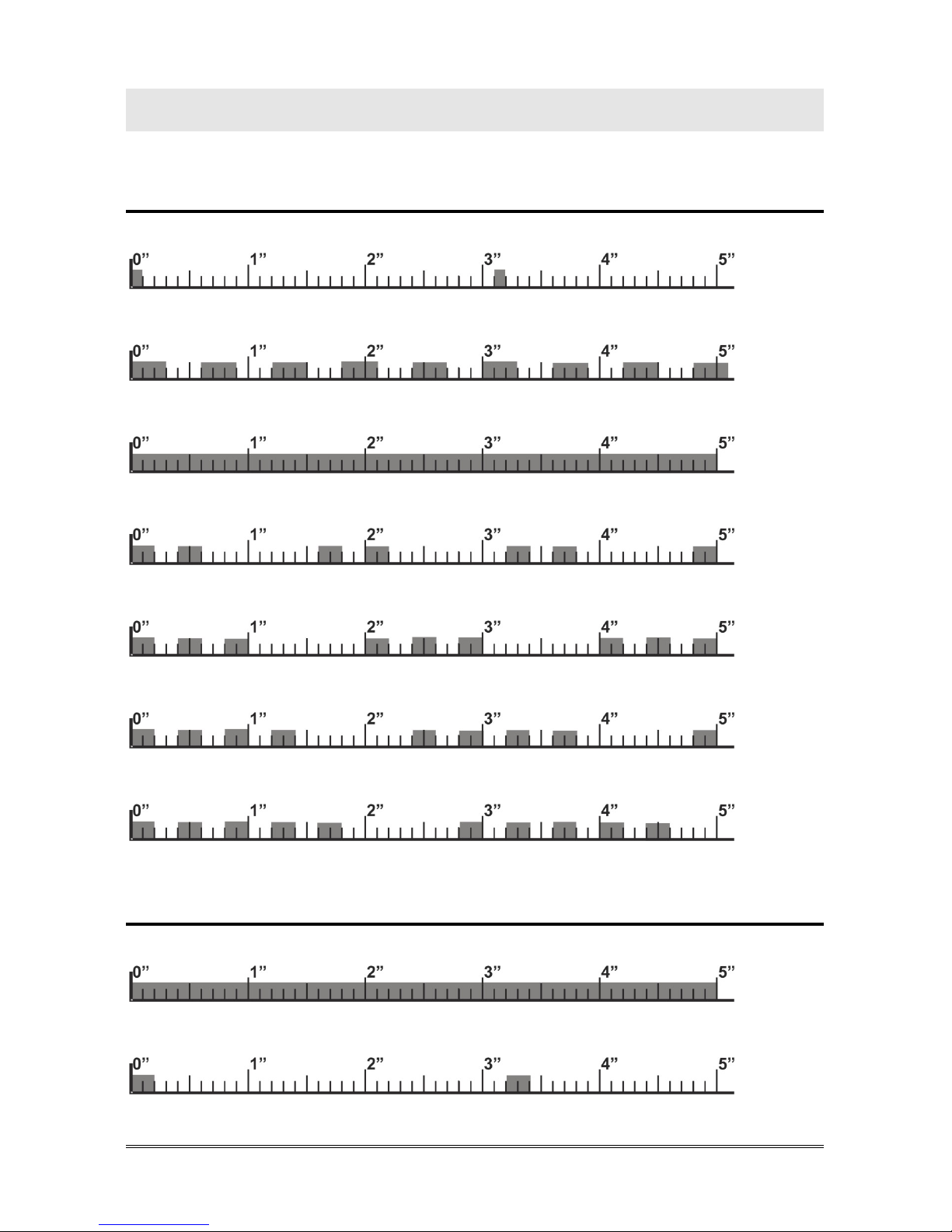
LED signalling device status (red)
Normal operation (no alarm)
Alarm
Voice connection
Battery disconnected or low battery (max. 1-hour operation in idle state)
2W speaker unit connection error or bus problem
Absence of telephone line
Button failure
LED signalling data transmission (white)
Data transmission in progress
GSM Satellite registered to COMNet Server
Page 30
Page 30 SIGNALS
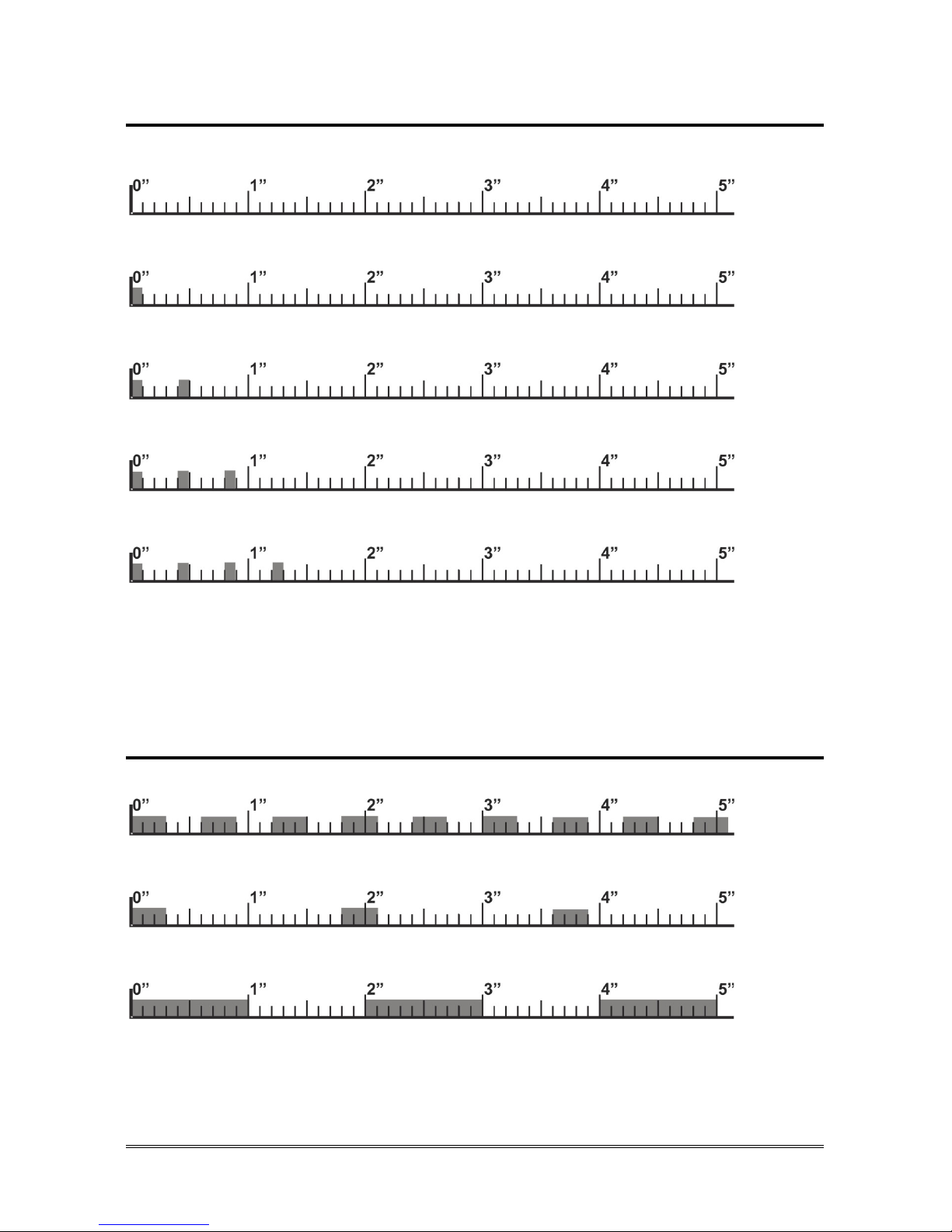
LED signalling GSM Satellite signal strength (green)
No signal
Low signal level
Medium signal level
Good signal level
High signal level
Note: the green LED on GSM satellite turns on during a call or when the
local telephone is used.
LED signalling alarm / periodical test call (yellow)
Emergency-call alarm
Emergency call alarm suspended
Other alarms - Test call
Page 31

SIGNALS Page 31
LED signalling power supply status (blue)
The external power supply is connected and the battery has max capacity
charge
The external power supply is connected and the battery has good capacity
charge
The external power supply is connected and the battery has medium
capacity charge
The external power supply is connected and the battery has low capacity
charge
The external power supply is connected and the battery is either
disconnected or dead
The external power supply is disconnected and the battery guarantees
more than 5-hour operation in idle state
The external power supply is disconnected and the battery guarantees
up to 5-hour operation in idle state
The external power supply is disconnected and the battery guarantees
2-hour operation in idle state
The external power supply is disconnected and the battery guarantees
1-hour operation in idle state
Page 32
Page 32 SIGNALS
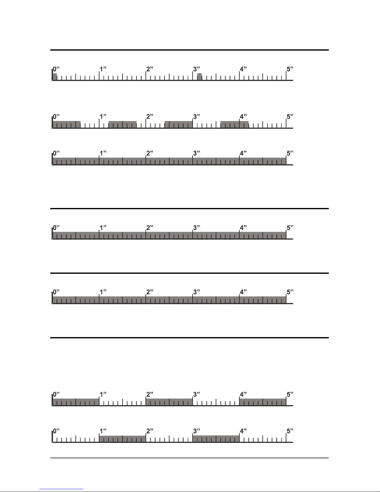
LED signalling GSM Satellite status (red)
GSM Satellite correctly registered on the network
GSM Satellite registering to the GSM network – GSM Satellite not
registered correctly – PIN request – PIN incorrect – Other problems
Call in progress
Given alarm indicator light (yellow)
Alarm
Received alarm indicator light (green)
Voice connection
Missed test call notification
The Given alarm indicator light and the Received alarm indicator light flash in
opposition to indicate the failure of the automatic test call.
The flashing sequence ends after the next successful test call or emergency call.
Given alarm indicator light
Received alarm indicator light
Page 33

EU DECLARATION OF CONFORMITY Page 33
EU DECLARATION OF CONFORMITY
Hereby, Esse-ti S.r.l. declares that the equipment type Helpy Controller is in
compliance with Directives 2014/30/EU - 2014/33/EU - 2014/35/EU.
The full text of the EU declaration of conformity is available from the
following Internet address:
https://www.esse-ti.it/en/dichiarazioni-di-conformita
Page 34

Page 34 NOTE
NOTE
Page 35

NOTE Page 35
Page 36

Esse-ti S.r.l.
Via G. Capodaglio, 9
62019 Recanati (MC) – ITALY
Tel. +39 071 7506066
Fax +39 071 7506057
www.esse-ti.it
[email protected]
 Loading...