


24/05/2016
User’s manual

Thanks for choosing
an Esse-ti product
This product has been especially designed for easy
operation. It has been manufactured with perfect
workmanship using suitable materials for long-lasting
performance.
All Esse-ti products are subjected to extensive reliability
and operational testing in our laboratories in order to
provide total guarantee for the user.
The User shall be responsible for defects arising from the use of the product. Esse-ti shall only be
responsible for defects according to and within the limitations set by the Presidential Decree dated
24/05/1988 no. 224 (fulfilling the EEC directive no. 85/374 on the harmonization of statutory and
administrative regulations of the Member States on the liability for damages arising from defective
products under art. 15 of Law no. 183 of 16 April 1987).
Esse-ti reserves the right to modify the product characteristics at any time without prior notice.

TABLE OF CONTENTS
GENERAL INSTALLATION INSTRUCTIONS .............................. 6
General Notes ................................................................................. 6
Making the installation ................................................................... 6
DESCRIPTION .................................................................................. 7
Features .................................................................................................... 7
LED .......................................................................................................... 8
INSTALLATION ............................................................................... 9
Inserting the SIM card ........................................................................... 10
Inserting the antenna .............................................................................. 10
Connection to the telephone line ........................................................... 11
Connection to the power supply ............................................................ 12
Turning the 3G.next gateway on ........................................................... 13
Gateway mounting operations ............................................................... 14
3G.next installation recommendations .................................................. 15
Absorption chart ..................................................................................... 15
PROGRAMMING VIA TELEPHONE ............................................ 16
Telephone line voltage ................................................................. 17
Use mode ..................................................................................... 18
Inter-digit dialling time ................................................................ 19
Country settings ........................................................................... 20
CLIP setting ................................................................................. 21
CLIR setting ................................................................................. 22
Permanent setting ................................................................................... 22
Temporary setting .................................................................................. 23
Roaming setting ........................................................................... 24
Provider's voicemail service deactivation .................................... 25
Setting telephone number for notification service ....................... 25
Setting the administrator telephone number ................................. 26
Programming password ................................................................ 27
Battery check ............................................................................... 28
Enabling ................................................................................................. 29
Programming the minimum value ......................................................... 29

External power failure control ...................................................... 30
Enabling ................................................................................................. 30
Relay-based notification of external power failure and/or
UMTS/GSM network loss ............................................................ 31
Automatic converter of selected telephone number ..................... 32
Entering preset numbers ........................................................................ 33
Matching telephone numbers manually ................................................. 35
Matching telephone numbers automatically .......................................... 36
Adjustments ................................................................................. 37
Relay settings ............................................................................... 38
Restoring default settings ............................................................. 39
Reset ............................................................................................ 40
PROGRAMMING VIA SMS ........................................................... 41
Message format ...................................................................................... 41
Notification message format .................................................................. 43
SERVICES ....................................................................................... 44
Incoming calls .............................................................................. 44
Outgoing calls .............................................................................. 44
Measuring the signal level ........................................................... 45
Reading the battery status ............................................................ 46
Reading “Automatic converter” numbers .................................... 47
Reading the relay status ............................................................... 48
Activation relay ............................................................................ 48
SENDING SMS THROUGH DB-9 ................................................. 49
DB-9 settings .......................................................................................... 49
Sending received SMS text messages through DB-9 connector ........... 51
Sending SMS from device wired in the DB-9 connector ...................... 53
DATA TRANSMISSION ................................................................ 54
FEMALE DB-9 CONNECTOR ....................................................... 57
SIGNALS ......................................................................................... 58
Tones ............................................................................................ 58
Call signals ................................................................................... 59
LED .............................................................................................. 59
UMTS/GSM signal indicator LED (GREEN) ....................................... 59
Status indicator LED (RED) .................................................................. 60

Line status indicator LED / Data transmission indicator LED (WHITE)
................................................................................................................ 60
Power supply status indicator LED (BLUE) ......................................... 61
PROBLEM-DETECTION GUIDE .................................................. 62

Page 6
GENERAL INSTALLATION
INSTRUCTIONS
GENERAL NOTES
Carefully read the notes contained in this section as they provide important
information on safe correct installation, use and maintenance of the product.
The product must be EXCLUSIVELY used for the purpose it was designed for.
Esse-ti shall not be responsible for damages arising from improper use.
The product has been designed in compliance with the regulations in force and
must be installed in systems that comply with the provisions of law.
Always disconnect power supply before performing internal or external operations
on the product (cleaning, maintenance, etc.).
Always refer to an authorized service centre for repair.
The device must be installed in a ventilated place, making sure that the ventilation
slots are never obstructed.
Do not install the product in environments with risk of explosion.
Make sure that the product has been installed as required.
Do not introduce objects, liquids or powders inside the product. Do not use sprays
inside the product.
Packing components (such as plastic bags, foam polystyrene, etc.) must be kept out
of the reach of children because potentially dangerous.
MAKING THE INSTALLATION
Internal telephone installations must be carried out by specialised personnel.
The installation and connection of telephone terminals to the telecommunications
network that do not comply with the regulations in force is not permitted.

Page 7
DESCRIPTION
3G.next is a device that, connected to a fixed telephone or to the PSTN
input terminals of a PABX or autodialer, allows you to make and receive
calls over the UMTS/GSM network. For correct operation the SIM card
must be enabled for voice and data traffic.
The 3G.next gateway comes with built-in backup batteries, a relay output
which can be activated either locally or remotely via SMS, a female DB-9
connector for data transmission and SMS forwarding, a micro USB A/B
port for direct connection to the UMTS/GSM module.
Features
Local programming via DTMF tones
Remote programming via SMS
Display of caller identification
Country setting
CLIP / CLIR
Roaming setting
Battery check
External power failure control
Relay-based notification of external power failure
Relay-based notification of UMTS/GSM network loss
SMS notifications (low-battery, dead battery, replaced battery,
external power failure/restore, UMTS/GSM network restore)
Measurement of UMTS/GSM signal level
Automatic converter of selected telephone number
Receiver and transmitter gain adjustment
Remote reboot function
Data transmission through standard RS-232 and CAN-bus (optional
RS-485)
Page 8
Incoming text messages transmission towards devices wired in the
DB-9 connector under RS-232 standard
Text messages transmission by devices wired into the DB-9
connector under RS-232 or CAN-bus standard
Remote firmware update
UMTS/GSM signal indicator LED
Status indicator LED
Line status indicator LED / Data transmission indicator LED
Power supply status indicator LED
Dual Band UMTS/GSM module
2W transmission power
12Vdc power supply input
230Vac external adapter input
Female DB-9 connector
Micro USB A/B port
Relay output
External antenna (cable length = 2m)
External adapter (230Vac 50Hz input; 12Vdc 500mA output; CE
mark)
LED
3G.next is equipped with 4 outer LEDs.
LEDs flashing is described at chapter “Signals” (see page 59).
Green LED: UMTS/GSM signal indicator LED
Red LED: Status indicator LED
/
White LED: Line status indicator LED / Data transmission
indicator LED
Blue LED: Power supply status indicator LED
Page 9
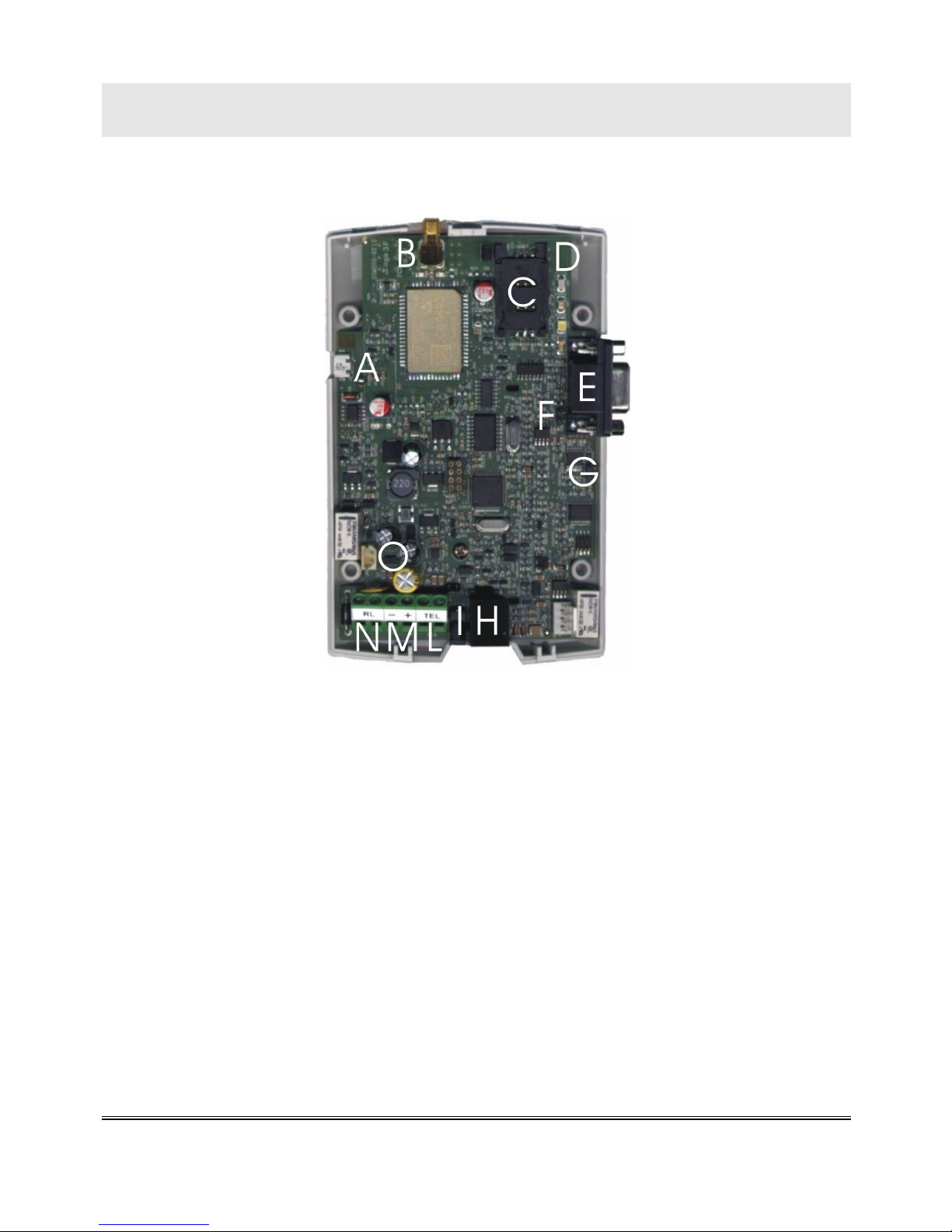
INSTALLATION
Remove the cover by pressing the upper side.
A Micro USB A/B port
B ANTENNA cable connector
C SIM CARD housing with front panel
D LED indicating signal strength (green), LED indicating device operation status
(red), LED indicating line status / data transmission (white) and LED indicating
power supply status (blue)
E Female DB-9 connector
F RS-485 termination jumper
G CAN-bus termination jumper
H Telephone line output (RJ11 connector) for telephone set connection or
autodialer/PABX analogue line connection
I 230Vac external adapter input
L Telephone line output (terminal block) for telephone set connection or
autodialer/PABX analogue line connection
M 12Vdc power supply terminal block
N Relay terminal block
O Backup battery connector
Page 10
Inserting the SIM card
Before inserting or replacing the SIM card, always make sure that the
gateway has been disconnected from the mains and take all necessary
measures to avoid electrostatic discharge.
Shift the SIM card housing cover downward until it unblocks and
lift it.
Carefully slide the SIM card into its housing cover.
Lower the SIM card housing cover and shift it upward until it
blocks.
WARNING
The SIM card PIN must be DISABLED. If the PIN is
enabled, it must be disabled through a mobile phone.
Inserting the antenna
Screw the antenna cable in to the connector on the top of the
module.
WARNING
NEVER connect 3G.next gateway without having
previously installed the antenna. The gateway may get
damaged.
WARNING
Do not install 3G.next near other electric or electronic
devices that were not especially designed to be used
with it. They could be subjected to RF interference
from the module.
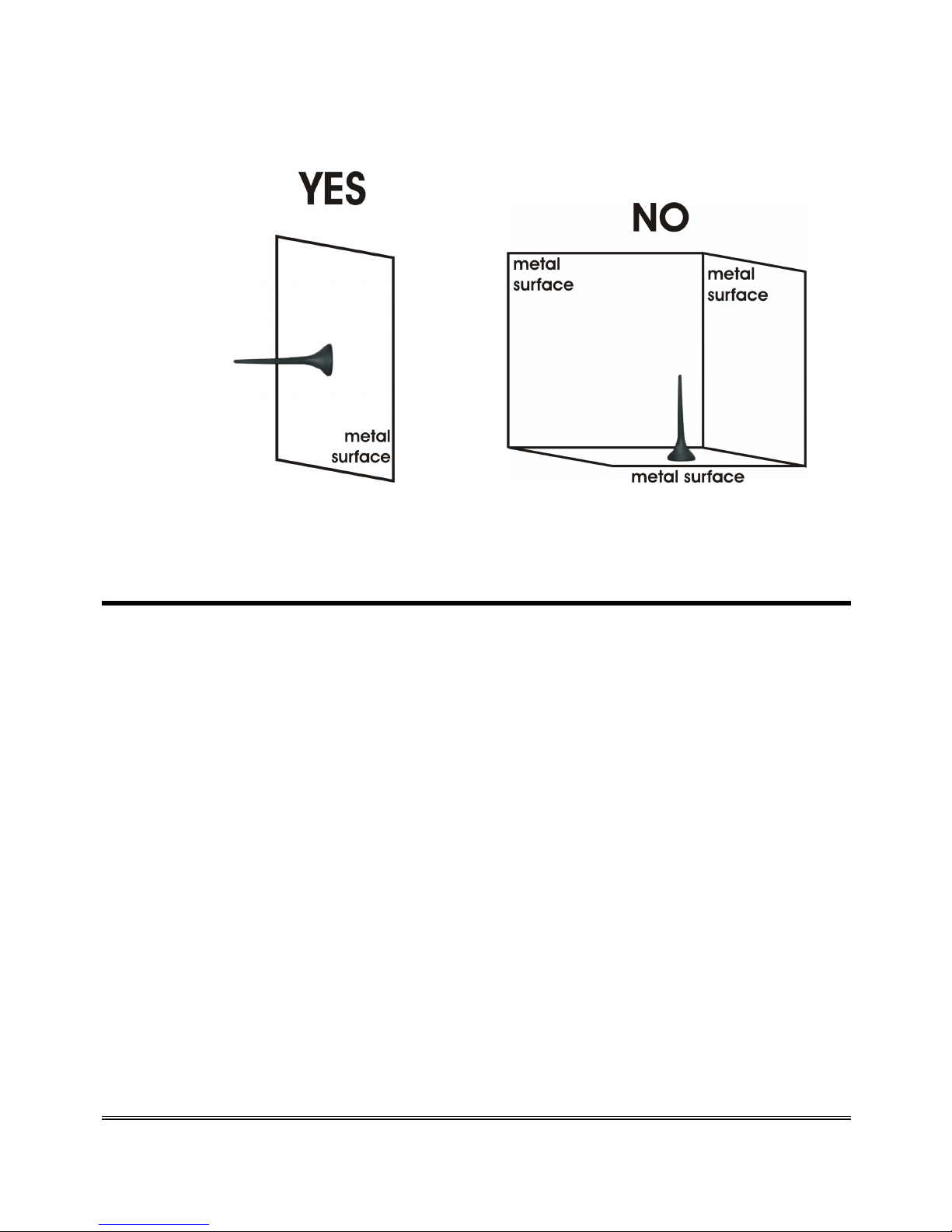
Page 11
Position the antenna with magnetic base so that any metal
surfaces do not block the signal.
Connection to the telephone line
Connect 3G.next to a standard telephone or to the PSTN input
terminals of a PABX or autodialer via the RJ-11 connector (H in the
picture at page 9);
or
Connect 3G.next to a standard telephone or to the PSTN input
terminals of a PABX or autodialer using the TEL terminals (L in the
picture at page 9).
Page 12
Connection to the power supply
Power supply via 230Vac external adapter
Connect the external adapter to the specific input (I in the picture
at page 9).
Connect the backup batteries to the dedicated input (O in the
picture at page 9).
Close the gateway cover.
or
12Vdc power supply
Connect the power supply cable to the terminals M (in the picture
at page 9) taking care to respect the polarity.
Connect the backup batteries to the dedicated input (O in the
picture at page 9).
Close the gateway cover, paying attention to the power supply
cable.
WARNING
Backup batteries may be connected only after 3G.next
has been supplied
Note: the max voltage to be supplied to the mains terminals
M is 17Vdc.
Note: the min. voltage required to supply 3G.next gateway
by the mains terminals M is 10Vdc.
Note: a protection cut-out switch must be installed upstream
to interrupt power supply in case of fault.

Page 13
Turning the 3G.next gateway on
Power 3G.next.
Wait 30 seconds after power-up to give time to 3G.next to register
correctly with the UMTS/GSM network.
Make sure the red LED (device status) flashes briefly once every 3
seconds as shown in chapter “Signals” (see page 60).
If the red LED flashes quicker and stays lit for a longer time (see page 60), the
gateway has not properly registered with the UMTS/GSM provider:
Disconnect 3G.next and make sure the SIM card is inserted
correctly and that the PIN is not locking it.
See chapter “Problem-detection guide” (page 62).
Page 14
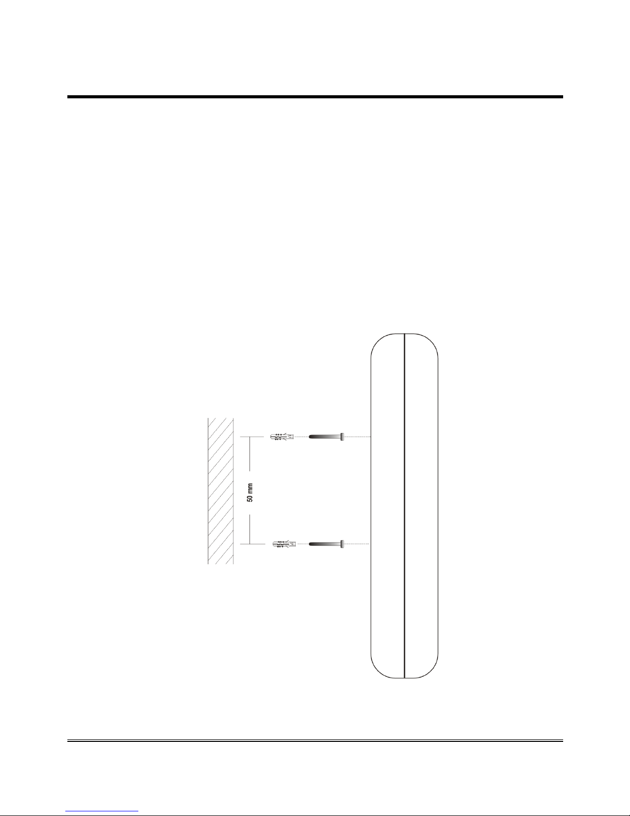
Gateway mounting operations
Check the UMTS/GSM signal strength through the green indicator
LED (see chapter “Signals”, page 59) and identify an area where
the signal is strong enough.
Note: the signal strength may vary according to the
telephone provider.
Drill two holes with 5 mm diameter on the wall at a distance of 50
mm.
Insert the 2 wall plugs and screws down until the screws are at a 5
mm distance from the wall.
Place 3G.next gateway onto the two screws through the two back
slots.
Page 15
3G.next installation recommendations
3G.next gateway must be installed in a location where the radio signal
allows for using the UMTS/GSM system.
It is advisable to leave plenty of space around the gateway for
maintenance operations.
Do not install 3G.next gateway outdoors, since it lacks protection
devices against weather conditions that can damage the gateway (water,
humidity, etc.).
Do not install 3G.next gateway near electronic (radio or TV sets,
Personal Computers, wired radio systems, etc.) or magnetic (credit
cards, etc.) devices that could be subjected to RF interference from the
module: recommended distance from the antenna is min. 2,5 m.
Do not install 3G.next gateway near medical devices. Its operation may
cause damage to hearing aids or pacemakers.
Always make sure that the device operation is permitted in the place of
installation (e.g. installation is not allowed in hospitals, airplanes, etc.).
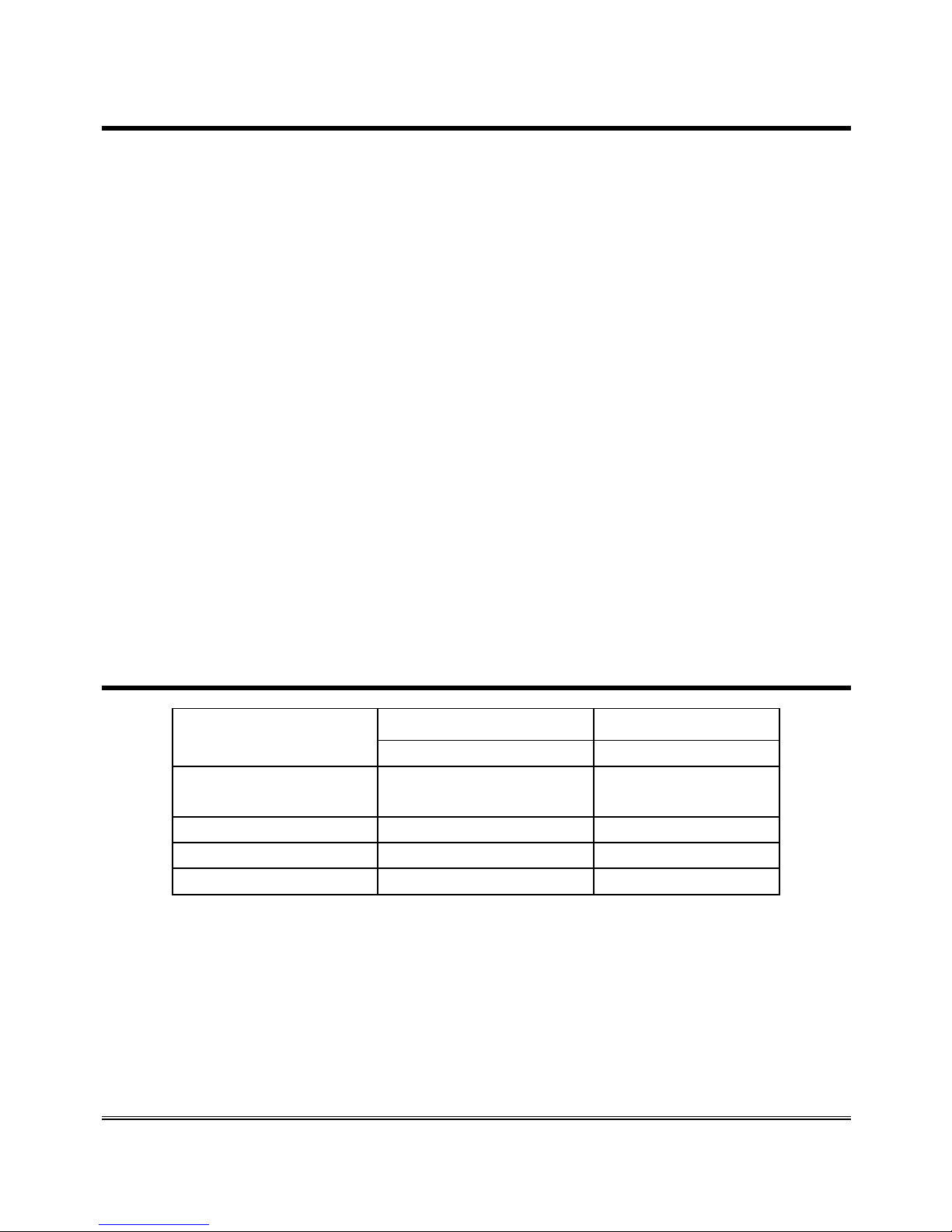
Absorption chart
Power supply
12Vdc 12Vdc
(battery not connected) (battery connected)
Telephone
handset down
40mA 60mA
Telephone handset up 80m
A
100mA
Conversation 130m
A
150mA
Data transmission 90m
A
110mA

Page 16
PROGRAMMING VIA
TELEPHONE
Allows you to customise the gateway according to your requirements.
Programming can be carried out locally via a MF telephone.
You can programme:
voltage of telephone line;
use mode;
inter-digit dialling time;
country settings (country calling code and international call prefix);
CLIP/CLIR settings;
roaming service settings;
provider's voicemail service deactivation;
notifications telephone number;
administrator telephone number ;
programming-mode password;
battery check;
external power failure control;
relay-based notification of external power failure;
relay-based notification of UMTS/GSM network loss;
automatic converter of selected telephone number;
receiver gain adjustment;
transmitter gain adjustment;
relay settings.
Note: during programming, the inter-digit dialling time must
not exceed 10 seconds. Once 10 seconds has elapsed
without digits you will hear the dissuasion tone and
you will have to hang up.
Note: at the end of each programming carried out correctly,
you will hear a confirmation tone, while an error tone
Page 17
will be heard in case of error. In any case, the
dialling tone will follow, after which you can proceed
with the programming or make a call.
Note: programming can be carried out even if the signal is
absent. After the confirmation or the error tones, he
dissuasion tone will follow, after which you can
proceed with programming or hang up.
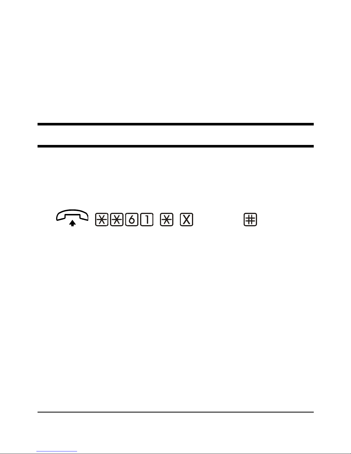
TELEPHONE LINE VOLTAGE
The following programming allows you to modify the voltage in the TEL
terminal and in the RJ-11 connector. A higher voltage may be required
for the proper functioning of specific devices.
Factory default: higher voltage (52Vdc).
(option) (confirm)
Lift the handset and dial: **61*.
Enter:
0 lower voltage (36Vdc);
1 higher voltage (52Vdc).
Dial # to confirm.
After the confirmation tone hang up or enter additional settings.
Page 18
USE MODE
3G.next delivers 4 different use modes which allow to improve
performance according to the specific devices being connected. They
should be selected in case the connected devices detect the telephone line
tones or when echo occurs during conversation.
Factory default: mode1.
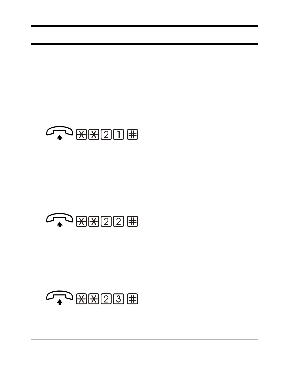
Mode 1
Factory default.
(confirm)
Lift the handset and dial: **21.
Dial # to confirm.
After the confirmation tone hang up or enter additional settings.
Mode 2
Use mode recommended for autodialers or other devices effecting tone
detection over the line.
(confirm)
Lift the handset and dial: **22.
Dial # to confirm.
After the confirmation tone hang up or enter additional settings.
Mode 3
Use mode recommended to reduce echo occurring during conversation.
(confirm)
Lift the handset and dial: **23.
Dial # to confirm.
Page 19
After the confirmation tone hang up or enter additional settings.
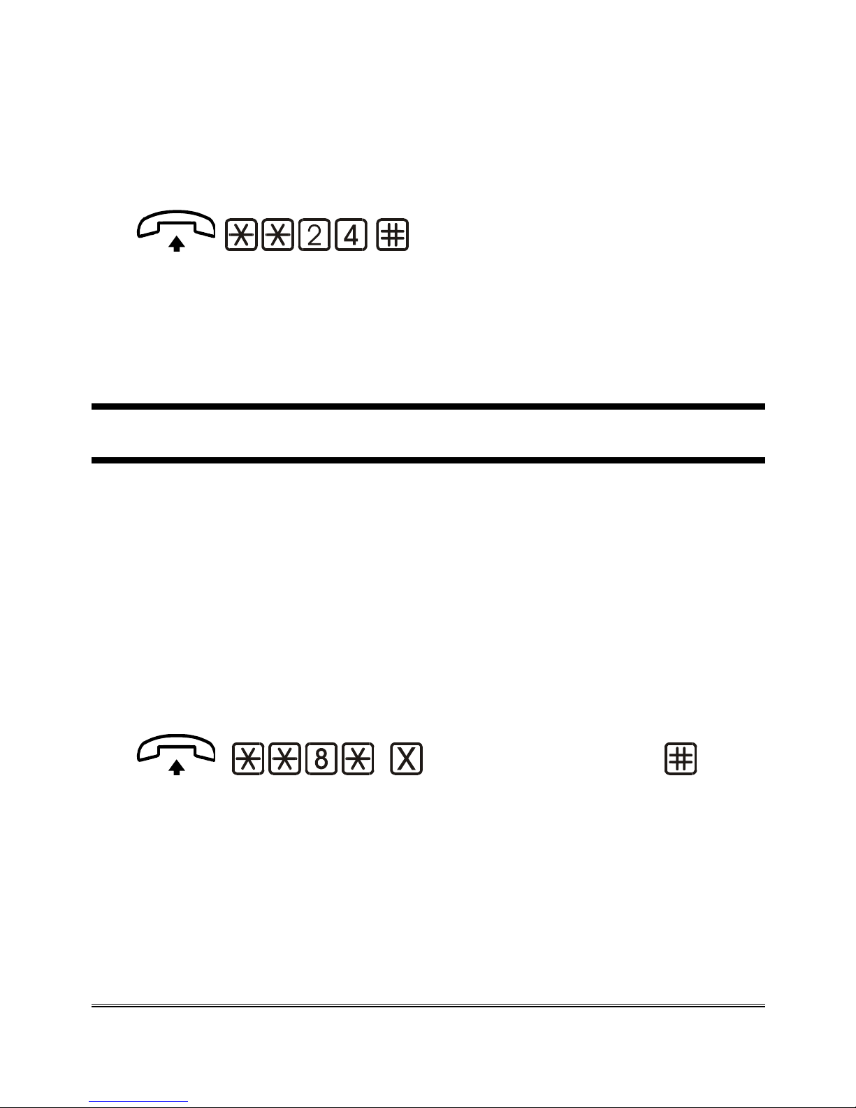
Mode 4
Use mode recommended to reduce echo in case of connection with
devices effecting tone detection over the line.
(confirm)
Lift the handset and dial: **24.
Dial # to confirm.
After the confirmation tone hang up or enter additional settings.
INTER-DIGIT DIALLING TIME
The inter-digit time is the maximum amount of time allowed between
digits while dialling a telephone number.
There are 2 ways to make outgoing calls:
Dial the telephone number and then press # to confirm. The call is
sent immediately.
Dial the telephone number and wait. The call will be sent after the
inter-digit time has elapsed.
Factory default: 5 seconds.
(inter-digit time)
(confirm)
Lift the handset and dial: **8*;
Dial the inter-digit dialling time:
0 inter-digit time: 10 seconds;
1-9 inter-digit time from 1 to 9 seconds.
Dial # to confirm.
Page 20
After the confirmation tone hang up or enter additional settings.
COUNTRY SETTINGS
This programming allows defining the country of use of 3G.next, in order
to set automatically the device with the proper parameters (if available).
For example the tones of the call change and on the display of a telephone
connected to 3G.next the calling number is shown without the area code.
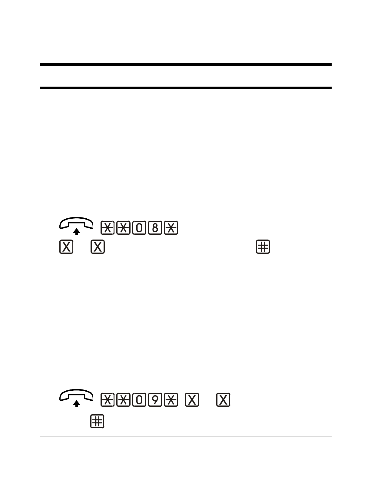
International call prefix
The international call prefix is the first part of a country’s code. For
example, the international dialling code for Italy, whose complete code is
0039, is 00.
Factory default:
00.
... (international call prefix) (confirm)
Lift the handset and dial: **08*;
Dial the international call prefix (max. 5 digits).
Dial # to confirm.
After the confirmation tone hang up or enter additional settings.
Country calling code
The country calling code is the second part of a country’s code. For
example, the
country calling code for Italy, whose complete code is 0039,
is 39.
Factory default: 39
.
... (country calling
code) (confirm)

Page 21
Lift the handset and dial: **09*;
Dial the country calling code (max. 5 digits).
Dial # to confirm.
After the confirmation tone hang up or enter additional settings.
CLIP SETTING
Upon an incoming call, if a telephone connected to 3G.next is provided
with a display, it will show the CLI (caller identification). Moreover, on
some telephones and some switchboards, it is also possible to display date
and time of the call. With this programming you can determine whether
to show the date and time of the call in addition to the caller’s number.
Factory default: date and time not displayed
.
Activation
(day/month/year)
(hh/mm) (confirm)
Lift the handset and dial: **7*1*.
Dial the day (two digits), the month (two digits) and the year (two
digits).
Dial *.
Dial the hour (two digits); dial the minutes (two digits).
Dial # to confirm.
After the confirmation tone hang up or enter additional settings.
Note: if 3G.next gateway remains off for a long time, it will
be necessary to repeat the activation procedure;

Page 22
otherwise the date and time displayed could be
incorrect.
Deactivation
(confirm)
Lift the handset and dial: **7*0.
Dial # to confirm.
After the confirmation tone hang up or enter additional settings.
CLIR SETTING
Permanent setting
Thanks to this programming you can decide whether to send out your
telephone number during outgoing calls.
Factory default: operation based on the service provided by your
provider
.
(option) (confirm)
Lift the handset and dial: **6*.
Enter:
0 operation based on the service provided by your
provider;
1 restriction active;
2 restriction not active.
Dial # to confirm.
After the confirmation tone hang up or enter additional settings.

Page 23
Note: if you choose option 1 your telephone number will not
appear on the call recipient’s display.
Temporary setting
The following programming allows you to modify the CLIR permanent
setting for one call only.
Enabling restriction for a call
Initial situation: CLIR restriction not active.
This programming allows you to activate the CLIR restriction for the
immediately subsequent call.
(confirm)
Lift the handset and dial:**16.
Dial # to confirm.
After the confirmation tone hang up or enter additional settings.
Disabling restriction for one call
Initial situation: CLIR restriction active.
This programming allows you to deactivate the CLIR restriction for the
immediately subsequent call.
(confirm)
Lift the handset and dial:**17.
Dial # to confirm.
After the confirmation tone hang up or enter additional settings.

Page 24
ROAMING SETTING
It allows to enable or disable the roaming function of 3G.next gateway.
When the roaming service is disabled, in case 3G.next registers with a
different provider than the programmed, it is not possible to make or
receive any calls. Such a condition is signalled by the following tone
sequence:
Factory default: roaming enabled.
Note: such setting is recommended for use under
neighbouring-countries areas, in order to avoid the
undesired selection of foreign operators.
Enabling roaming service
(confirm)
Lift the handset and dial: **5*1.
Dial # to confirm.
After the confirmation tone hang up or enter additional settings.
Disabling roaming service
It allows to select a specific SIM’s provider by disabling 3G.next’s
operation with any other provider .
(MCC) ... (MNC) (confirm)
Lift the handset and dial: **5*0*.

Page 25
Select the specific SIM’s provider by dialling the related MCC
(Mobile Country Code) and MNC (Mobile Network Code) codes.
Dial # to confirm.
After the confirmation tone hang up or enter additional settings.
PROVIDER'S VOICEMAIL SERVICE
DEACTIVATION
It allows to deactivate the provider’s voicemail.
(confirm)
Lift the handset and dial: **31.
Dial # to confirm.
After the confirmation tone hang up or enter additional settings.
SETTING TELEPHONE NUMBER FOR
NOTIFICATION SERVICE
It allows to enter the telephone number appointed for SMS notifications
of external power failure/restore, UMTS/GSM network restore, lowbattery, dead battery, replaced battery, battery status.
... (telephone number)
... (telephone number) (confirm)

Page 26
Lift the handset and dial: **40*.
Enter the telephone number to which the notification SMS must be
sent.
Dial *.
Enter again (for confirmation) the telephone number to which the
notification SMS must be sent.
Dial # to confirm.
After the confirmation tone hang up or enter additional settings.
Deleting
It allows to delete the telephone number appointed for SMS notifications
or warnings.
(confirm)
Lift the handset and dial: **40.
Dial # to confirm.
After the confirmation tone hang up or enter additional settings.
SETTING THE ADMINISTRATOR TELEPHONE
NUMBER
SMS programming mode may be effected by any mobile phone or other
device sending out SMS. After setting the administrator telephone
number, programming mode via SMS is only allowed by the
administrator’s telephone number.
Note: once it has been entered, the administrator number
will receive the notification SMS related to the
“Automatic converter” service.
Note: for a proper use please enter first the country code
and then the administrator number without the first

Page 27
zero (for example: if the administrator number is
07715123456 and 3G.next is located in England
please enter 00447715123456).
... (telephone number)
... (telephone number) (confirm)
Lift the handset and dial: **18*.
Enter the administrator telephone number.
Dial *.
Enter the administrator telephone number again (for confirmation)
Dial # to confirm.
After the confirmation tone hang up or enter additional settings.
Deleting
It allows to delete the administrator telephone number.
(confirm)
Lift the handset and dial: **18.
Dial # to confirm.
After the confirmation tone hang up or enter additional settings.
PROGRAMMING PASSWORD
It allows to change the programming password.
Factory default: 0.
Note: make sure the password has been noted down. In case
it is lost, please contact the nearest technical service
center.

Page 28
(password)
(password) (confirm)
Lift the handset and dial: **19*.
Enter the new programming password (max. 3 digits).
Dial *.
Enter the new password again (for confirmation).
Dial # to confirm.
After the confirmation tone hang up or enter additional settings.
BATTERY CHECK
If the battery check is enabled, in case of power failure the 3G.next
checks the battery status every second. When the charge goes below the
previously-programmed threshold ensuring the minimum number of
operating hours in idle mode, a notification SMS is sent to the
programmed telephone number (see “Setting telephone number for
notification service”). The device sends out one notification SMS only. A
new SMS will be sent out if the charge status rises and goes again below
the previously-set threshold.
The SMS text is the following: “Low battery”.
The built-in backup batteries ensure 8 operating hours in idle mode and 1
operating hour in conversation mode.
If the battery check is enabled , every 15 days the 3G.next controls the
integrity of the battery. If the battery is found dead or damaged, a
notification SMS is sent to the programmed number with the following
text message: “Dead battery”.
If the battery check is enabled, the 3G.next detects the presence of the
battery. If the battery is absent or in case of disconnection, a notification

Page 29
SMS is sent to the programmed number with the following text message:
“Dead battery”.
When the battery is reconnected (or replaced, if found damaged), a
notification SMS is sent to the programmed number with the following
text message: “Replaced battery”.
Factory default: disabled.
Enabling
It allows to activate the battery check.
Enabling
(confirm)
Lift the handset and dial: **50.
Dial # to confirm.
After the confirmation tone hang up or enter additional settings.
Disabling
(confirm)
Lift the handset and dial: **51.
Dial # to confirm.
After the confirmation tone hang up or enter additional settings.
Programming the minimum value
It allows to set the min. number of operating hours in idle mode. Below
this threshold, a notification SMS is sent out.
Factory default: 4 hours.
(value) (confirm)

Page 30
Lift the handset and dial: **52*.
Enter the value (0 ~ 7) according to the table below:
0 1 2 3 4 5 6 7
7h 6h e 30’ 6h 5h e 30’ 4h 2h e 30’ 1h e 30’ 1h
Dial # to confirm.
After the confirmation tone hang up or enter additional settings.
EXTERNAL POWER FAILURE CONTROL
If the control on external power failure is enabled, the 3G.next constantly
controls the external power supply (230Vac or 12Vdc). If the external
power failure lasts longer than the preset time interval, a notification SMS
is sent to the programmed telephone number (see “Setting telephone
number for notification service”).
The SMS text is the following: “External power failure”.
A new SMS will be sent if the external power supply is restored for a
time interval equal to the preset threshold.
The SMS text is the following: “External power restored”.
Factory default: disabled.
Enabling
It allows to activate the external power failure control.
Enabling
(minutes) (confirm)
Lift the handset and dial: **81*.
Enter the minutes of external power failure/restore (3 ~ 9).
Dial # to confirm.

Page 31
After the confirmation tone hang up or enter additional settings.
Disabling
(confirm)
Lift the handset and dial: **81*0.
Dial # to confirm.
After the confirmation tone hang up or enter additional settings.
RELAY-BASED NOTIFICATION OF EXTERNAL
POWER FAILURE AND/OR UMTS/GSM
NETWORK LOSS
It allows to use the relay output to signal the absence/restoration of:
- the external power supply (230Vac or 12Vdc)
- the UMTS/GSM network.
Note: when the UMTS/GSM network is restored, a
notification SMS is automatically sent to the
programmed telephone number (see “Setting
telephone number for notification service”). The
SMS text is the following: “Mobile network
restored”.
Factory default: both notifications disabled.
(option) (confirm)
Lift the handset and dial: **94*.
Enter:
0 both notifications disabled;
1 the relay is deactivated in case of external power failure;

Page 32
2 the relay is deactivated in case of UMTS/GSM network
loss;
3 the relay is deactivated in case of external power failure or
in case of UMTS/GSM network loss;
4 the relay is activated in case of external power failure;
5 the relay is activated in case of UMTS/GSM network loss;
6 the relay is activated in case of external power failure or in
case of UMTS/GSM network loss.
Dial # to confirm the entered parameter.
After the confirmation tone hang up or carry on with other
programmings.
AUTOMATIC CONVERTER OF SELECTED
TELEPHONE NUMBER
This service allows to enter up to 5 telephone numbers automatically
receiving any outgoing call, regardless of the real telephone numbers
dialled out by the telephone or autodialer connected to 3G.next gateway.
Each preset telephone number is matched with a corresponding telephone
number , either by programming and/or automatic learning. When dialing
out the corresponding telephone number , 3G.next will make a call to the
previously-matched telephone number instead of calling the real one.
When dialing out a telephone number not associated with any preset
number, the call will be automatically forwarded to the first preset
telephone number.
Note: to enable the “Automatic converter” service, you
simply need to preset one telephone number; to
disable this service, all preset telephone numbers
must be deleted.
Example:
preset table:

Page 33
Location Selected tel. number Preset tel. number
1 3331234567 0717506065
2 3339876543 0717506066
3 0733434343 0717506067
4 0733445566 0717506068
5 0733778899 0717506069
- when selecting tel. number 3331234567, 3G.next will make a call
to 0717506065;
- when selecting number 3339876543 , 3G.next will make a call to
0717506066;
- etc;
- when selecting any number not included in the “Selected
telephone number” column, 3G.next will send a call to the first
telephone number included in the “Preset telephone number”
column.
Entering preset numbers
It allows to enter up to 5 telephone numbers receiving any outgoing call
sent out by 3G.next.
(password)
(location)
... (telephone number)
... (telephone number) (confirmation)
Lift the handset and dial : **26*.
Enter the programming password.
Dial: *.
Enter the desired telephone number location (from 1 to 5) in the
related table.
Dial *.

Page 34
Enter the telephone number to be preset.
Dial *.
Enter again the telephone number to be preset.
Dial # to confirm the entered parameter.
After the confirmation tone hang up or enter additional settings.
Deleting a preset telephone number
It allows to delete a preset telephone number.
(password)
(location) (confirmation)
Lift the handset and dial: **26*.
Enter the programming password.
Dial *.
Enter the location of the telephone number to be deleted.
Dial # to confirm.
After the confirmation tone hang up or enter additional settings.
Deleting all preset telephone numbers.
It allows to delete all the preset telephone numbers.
(password)
(confirmation)
Lift the handset and dial: **26*.
Enter the programming password.
Dial *.
Dial # to confirm.
After the confirmation tone hang up or enter additional settings.

Page 35
Matching telephone numbers manually
It allows to associate a specific telephone number to each preset number.
Note: in case no telephone number is manually matched to
any preset number, the association is automatically
carried out by auto- learning procedure.
(password)
(location)
... (telephone number)
... (telephone number) (confirmation)
Lift the handset and dial: **25*.
Enter the programming password.
Dial *.
Enter the position of the preset number to be matched, 1 to 5.
Dial *.
Enter the telephone number to be matched.
Dial *.
Enter again the telephone number to be matched.
Dial # to confirm the entered parameter.
After the confirmation tone hang up or enter additional settings.
Deleting a previously matched telephone number.
It allows to delete a telephone number previously matched with a preset
number.

Page 36
(password)
(location) (confirmation)
Lift the handset and dial: **25*.
Enter the programming password.
Dial *.
Enter the location of the telephone number to be deleted, 1 to 5.
Dial # to confirm
After the confirmation tone hang up or enter additional settings.
Deleting all previously-matched telephone numbers.
It allows to delete all previously-matched telephone numbers associated
with preset numbers.
(password)
(confirmation)
Lift the handset and dial: **25*.
Enter the programming password.
Dial *.
Dial # to confirm.
After the confirmation tone hang up or enter additional settings.
Matching telephone numbers automatically
The auto-learning procedure allows to match automatically each preset
number with the selected numbers dialed by the telephone and/or
autodialer connected with 3G.next.
Enter the preset numbers after the corresponding programming
codes.
Select a telephone number to be called by the telephone or
autodialer connected with 3G.next module.

Page 37
3G.next will check if the number is already matched with a preset
telephone number. If so, it will send a call to the preset number; if not, it
will match the selected number to the first available preset number and
will make a call to it.
In case there are not available preset numbers, but it’s still possible to
make associations, the selected number will be automatically matched
with the first preset number.
In case all 5 possible associations have been effected, the call will be sent
to the first preset number.
An SMS containing the selected number and the preset number is sent out
to the administrator number (if present) upon creating any new matching.
An SMS is also sent out every time a different selection from the 5 preset
ones is effected.
ADJUSTMENTS
This programming allows you to adjust the receiver gain as well as the
transmitter gain.
WARNING
The factory-default settings are optimal values, please
do not change them unless it is strictly necessary.
Transmission
Factory default: +6dB.
(value) (confirm)
Lift the handset and dial: **10*.
Enter the value (1 ~ 7) according to the table below:

Page 38
1 2 3 4 5 6 7
-2dB 0dB +4dB +6dB +9dB +11dB +12dB
Dial # to confirm.
After the confirmation tone hang up or enter additional settings.
Reception
Factory default: -8dB.
(value) (confirm)
Lift the handset and dial: **11*.
Enter the value (1 ~ 5) according to the table below:
1 2 3 4 5
-8dB -6dB -4dB -2dB 0dB
Dial # to confirm.
After the confirmation tone hang up or enter additional settings.
RELAY SETTINGS
This programming allows you to configure the relay output either as
bistable or monostable (by defining the duration of the impulse in
seconds). This programming only applies when the relay is not used to
signal the external power supply and/or UMTS/GSM network failure.
Factory default: monostable (1s).
Note: the relay can command loads with up to 1A to 24V
absorption.

Page 39
(value)
(confirm)
Lift the handset and dial: **93*.
Enter:
00 bistable output replay (the relay is activated or
deactivated by the code digited by the user during
operation);
01
~99 monostable output relay (the relay executes an impulse
of the time length preset in seconds).
Dial # to confirm.
After the confirmation tone hang up or enter additional settings.
RESTORING DEFAULT SETTINGS
It is possible to restore the factory - default settings at any time, by
dialling:
(confirm)
Lift the handset and dial: **99.
Dial # to confirm.
After the confirmation tone hang up or enter additional settings.
The factory-default values are:
Telephone line voltage 52Vdc
Use mode mode 1
Inter-digit dialling time 5s
International call prefix 00
Country calling code 39

Page 40
CLIP disabled
CLIR depends on the provider
Roaming enabled
Battery check disabled / 4h
External power failure control disabled
Relay-based notifications disabled
Transmitter gain +6dB
Receiver gain -8dB
Relay settings monostable 1s
Note: restoring factory default does not modify the
programming password and the settings entered for
the “Automatic Converter” service.
RESET
You can reset 3G.next gateway at any time, without powering it off, with
the following code:
(confirm)
Lift the handset and dial: **98.
Dial # to confirm.
Hang up.
Note: resetting 3G.next gateway does not modify its
programming profile.

Page 41
PROGRAMMING VIA SMS
Programming via SMS is possible by any mobile phone or other device
supporting SMS. In case the administrator number has been previously
set, programming via SMS is only allowed from such telephone number.
An SMS notifying that programming has been completed will be sent
back by 3G.next to the same telephone number that forwarded the
programming SMS.
WARNING
Programming outgoing SMS from the Internet may
not be successful if the requested format is not
respected.
Message format
Each programming SMS must contain the password, allowing to access
programming, and the codes corresponding to the desired settings.
The message format is required to be as follows:
ET-IU1*xxx#c..c#
Where:
ET-IU1 : programming string start
*xxx# : password string (default xxx = 0)
c..c : programming string as per table below
# : separator character or end string character

Page 42
Programming Code (c..c)
Telephone line voltage 61*X
Use mode 2X
Inter-digit dialling time 8*X
International call prefix 08*X..X
Country calling code 09*X..X
CLIP activation 7*1*ggmmaa*hhmm
CLIP deactivation 7*0
CLIR permanent setting 6*X
CLIR temporary activation 16
CLIR temporary deactivation 17
Enabling roaming service 5*1
Disabling roaming service 5*0*XXXYYY
Setting telephone number for notification service 40*X…X*X…X
Deleting notification numbers 40
Setting administrator number 18*X…X*X…X
Deleting administrator number 18
Setting programming password 19*XXX*XXX
Battery check enabling 50
Battery check disabling 51
Low-battery check minimum value 52*X
External power failure control enabling 81*X
External power failure control disabling 81*0
Relay-based notifications 94*X
Entering preset number 26*XXX*X*X…X*X…X
Deleting preset number 26*XXX*X
Deleting all preset numbers 26*XXX*
Reading preset numbers 26*XXX*XR
Entering selection 25*XXX*X*X…X*X…X
Deleting selection 25*XXX*X
Deleting all selections 25*XXX*
Reading selections 25*XXX*XR
Transmitter gain setting 10*X
Receiver gain setting 11*X
Relay settings 93*XX
Restoring default settings 99
Reset 98
Measuring the UMTS/GSM signal level 30
Reading battery status 91

Page 43
Reading relay status 92
Relay activation 92*X
For each programming refer to the relevant paragraph.
Example:
it is required to enable battery check and to set the telephone
number for notifications.
Outgoing message text:
ET-IU1*0#50#40*X..X*X…X#
Notification message format
The format of the message notifying the user or the administrator who
previously sent out a programming SMS, is the same as the programming
message format.
SMS notifying an accepted command:
ET?IU1*xxx#c..c#
SMS notifying a rejected command:
ET?IU1*xxx#c..cERR#
Example:
outgoing SMS to enable battery check and to set the following
incoming notification number: 3330123456.
Outgoing message text:
ET-IU1*0#50#40*3330123456*3330123456#
Message text notifying accepted command:
ET?IU1*0#50#40*3330123456*3330123456#

Page 44
SERVICES
INCOMING CALLS
Allows you to answer incoming calls.
Upon receiving a phone call, the LED indicating the line status (white)
will blink shortly 4 times every 4 seconds as described at chapter
“Signals” (see page 60) and the telephone will be ringing.
Pick up the handset;
The LED indicating the line status (white) and the LED indicating the
device status (red) will turn on and the communication with the calling
party will be set up.
OUTGOING CALLS
Allows you to dial over the UMTS/GSM network.
If 3G.next gateway is connected to a PABX, please refer to the
switchboard’s manual.
If 3G.next gateway is connected to a telephone:
Pick up the handset.
The LED indicating the line status (white) will turn on and the dialling
tone will be heard.
Dial the telephone number to be called.
When the called party answers, the LED indicating the device status (red)
will turn on.
Note: once you have dialled the number, you can either
press # to send the number immediately, or you can
wait for the call to be automatically forwarded once
the inter-digit dialling time has elapsed (by default 5
seconds).

Page 45
Note: in the event you receive the dissuasion tone picking up
the handset, check if the signal is present and make
sure the SIM card is working correctly.
MEASURING THE SIGNAL LEVEL
This procedure allows you to check the UMTS/GSM signal level through
your telephone.
(tones)
Lift the handset.
Dial: **30#;
Wait for the signal reading.
The system will send a number of short tones corresponding to the signal
level:
Tones Qualit
y
No signal No signal
1 Tone Low
2 Tones Medium
3 Tones Good
4 Tones High
Since the signal can be subject to variations, we recommend repeating the
code **30#, 2 or 3 times a few seconds apart, in order to have a reliable
measurement.
Note: in case of low signal, we recommend installing
3G.next in a different area with a better signal.
Note: if you receive the “no signal” tone, it means that the
gateway has not been registered correctly by the
provider. We recommend trying again after a few

Page 46
moments, and in case of no result, make sure that the
SIM card is working correctly.
READING THE BATTERY STATUS
If the battery check has been previously enabled, it is possible to check
the battery status.
(confirm)
Lift the handset and dial: **91#.
After the confirmation tone hang up.
After receiving the request, 3G.next will send an SMS to the number
programmed to be alerted.
The outgoing message text is the following: “Battery level: x”, where x is
the value corresponding to the minimum number of operating hours
guaranteed by the battery in idle mode, according to the table at
paragraph “Battery check”.
The request will not be accepted (an error tone will be received) if the
battery check is disabled, if the notification number to be alerted has not
been previously entered or if 3G.next is not correctly registered to the
UMTS/GSM network.

Page 47
READING “AUTOMATIC CONVERTER”
NUMBERS
It is possible to check remotely, via SMS, the preset numbers and the
stored selected numbers (see chapter “Programming via SMS” for the
use of SMS).
Reading preset numbers
The programming code to be contained in the message text must be the
following :
where:
XXX: programming password
X: preset number location
Reading previously selected numbers
The programming code to be contained in the message text must be the
following:
dove:
XXX: programming password
X: selected number location
An answer message will be returned to user or the system administrator
who sent out the SMS.
Example :
an SMS has been sent out to ascertain the preset number stored
at location 1 (071123456).
Outgoing message text:
ET-IU1*0#26*0*1R#
Answer message text:
ET?IU1*0#26*0*1R071123456#

Page 48
READING THE RELAY STATUS
It is possible to check remotely, via SMS, the relay status (see chapter
“Programming via SMS” for the use of SMS).
The programming code to be entered in the text message must be as
follows:
An answer message will be returned to user or the system administrator
who sent out the SMS.
Text included in the return message if relay is OFF:
920
Text included in the return message if relay is ON:
921.
ACTIVATION RELAY
Allows you to activate or deactivate the relay when it is not used to signal
the external power supply and/or UMTS/GSM network failure.
(value) (confirm)
Lift the handset and dial: **92*.
Enter:
0 to deactivate the relay (bistable only);
1 to activate the relay.
Dial # to confirm.
After the confirmation tone hang up.

Page 49
SENDING SMS THROUGH DB-9
3G.next allows to:
- send received SMS text messages to devices wired in the DB-9
connector (in RS-232 standard);
- send SMS text messages from devices wired in the DB-9 connector (in
RS-232 or CAN-bus standard).
DB-9 settings
Communication standard
It allows to define the communication standard utilized via
DB-9 connector.
Default: RS-232.
(standard) (confirm)
Lift the handset and dial: **12*.
Enter:
0 communication disabled;
1 RS-232;
3 CAN-bus.
Dial # to confirm.
After the confirmation tone carry on with the following
programming of the communication parameters.
Note: for CAN-bus communication please refer to
corresponding documentation.
Serial communication settings
It allows to set the parameters required for serial communication.
Default: 115200/8/1/none.

Page 50
Note: this programming can be effectuated only after the
communication standard programming.
(bits per second)
(data bits) (stop bits) (parity)
(confirm)
Lift the handset and dial: **57*.
Enter the parameter for the bits per second according to the table
below:
parameter RS-232 CAN-bus
1 115200 1M
2 57600 500k
3 38400 250k
4 19200 125k
5 9600 64k
6 4800 50k
7 2400 20k
8 1200 10k
9 600 5k
Dial 0 (data bits = 8).
Dial 0 (stop bits = 1) or 1 (stop bits = 2).
Dial 0 (parity = none) or 1 (parity = even) or 2 (parity = odd).
Dial # to confirm.
After the confirmation tone hang up or enter additional settings.
Note: for CAN-bus communication please dial
**57* X(bits per second) 000#.

Page 51
Sending received SMS text messages
through DB-9 connector
This parameter allows to forward text messages received by 3G.next to
devices wired in the DB-9 connector (in RS-232 standard).
The format of incoming text messages is required to be as follows:
&XXXXy…y
Where:
& : string start
XXXX : identification code (alphanumeric)
y..y : text forwarded through DB-9 connector.
An SMS notifying that the message has been delivered will be sent back
by 3G.next to the same telephone number that forwarded the SMS with
the identification code.
The notification message is:
OK#
Note: text messages (SMS) with more than 160 digits are
divided by the operator in many text messages (SMS);
3G.next sends a notification per each text message
received.
Note: identification codes containing letters can be
programmed only via SMS.
(3G.next programming password)
(identification code)
(identification code) (confirm)
Lift the handset and dial: **71*.

Page 52
Enter the 3G.next programming password (default XXX = 0).
Dial *.
Enter the identification code (4 digits).
Dial *.
Enter the identification code (for confirmation).
Dial # to confirm.
After the confirmation tone hang up or enter additional settings.
Deleting
It allows to disable forwarding the incoming text messages through the
DB-9.
(3G.next programming password)
(confirm)
Lift the handset and dial: **71#.
Enter the 3G.next programming password (default XXX = 0).
Dial # to confirm.
After the confirmation tone hang up or enter additional settings.

Page 53
Sending SMS from device wired in the DB-9
connector
It allows external devices wired in the DB-9 connector (in RS-232 or
CAN-bus standard) to send SMS text messages.
The text format transmitted by the external device to 3G.next, through the
DB-9 connector in RS-232 standard, is required to be as follows:
SMSx…x:y…y<CTRL+Z>
Where:
SMS : string start
x…x : telephone number on which the SMS must be sent
y...y : message text to be sent (max. 160 characters)
<CTRL+Z> : non-editable character defining end of text.
The SMS can be sent on a 3G.next preset number (see “Setting telephone
number for notification service”). In this case, the text format is required
to be as follow:
SMS:y…y<CTRL+Z>
Note: to send SMS, 3G.next must be correctly registered to
the UMTS/GSM network and the SIM card must be
topped up. Moreover, 3G.next must not be engaged
with an ongoing voice call by the time the message
text is received from the external device.
Note: 3G.next does not send the external device any
notification of failed/successful SMS delivery. 3G.next
is capable of notifying the external device an SMS
feedback received by the remote recipient (see
“Sending received SMS text messages through DB-9
connector”).
Note: for CAN-bus communication please refer to
corresponding documentation.

Page 54
DATA TRANSMISSION
The COMNet system allows users to connect remotely with devices
equipped with RS232/RS485/CAN BUS, replacing traditional serial
communication which is commonly performed locally (i.e. between
peripherals and custom boards – Fig. A – or between a PC-based
proprietary application and a lift controller board – Fig. B –).
Figure A: example of local serial communication
Figure B: example of local serial communication
Figure C: general example of remote serial communication

Page 55
Setting up a COMNet system requires:
- connecting a 3G.next gateway (properly programmed) to the serial port
of the remote device to be controlled; the SIM card to be inserted into
3G.next gateway must be enabled for voice and data traffic;
- installing the COMNet PC Client software in the PC which will be
used for remote-monitoring; the PC must be able to access the Internet.
Figure D: example of COMNet system
Figure E: example of COMNet system
The COMNet system exclusively allows to set up a remote two-way data
communication. The data flow coming out of the remote device will be
sent to the same application commonly used for local wired
communication or to the a physical COM port of the computer.

Page 56
The connection procedure simply requires to enter the SIM card
telephone number associated with the remote 3G.next into the COMNet
PC Client. This eliminates any difficulties in locating remote devices not
assigned to static IP addresses.
The data connection is established by the system on demand and the data
are transferred over an Esse-ti proprietary server (COMNet Server).
The 3G.next connected to the remote device to be monitored, may also be
used as a standard gateway for voice transmission, by means of the
dedicated plug or connector (i.e. it can be connected with the elevator
emergency phone dialer) and the same SIM card needed for remote
monitoring. The voice call is always privileged over the data
transmission, therefore in case of a voice emergency call, the ongoing
data connection will be automatically cut off.
Figure F: example of COMNet system with 3G.next
used as gateway for voice transmission
Please see the user manual of the COMNet for the data transmission
programming of 3G.next and for the installation and use of the COMNet
PC client software..

Page 57
FEMALE DB-9 CONNECTOR
RS-232
TX PIN2
RX PIN3
GND PIN5
RS-485
TXD- PIN6
TXD+ PIN7
GND PIN5
CAN-bus
CANH PIN8
CANL PIN9
GND PIN5

Page 58
SIGNALS
TONES
Dialling
It indicates that 3G.next is ready for dialing.
Dissuasion
It indicates that the 3G.next has not properly registered with the GSM provider or
a delay in dialling or the end of conversation or an access to services not
permitted.
Busy
It indicates that the called party is busy.
Confirmation
It indicates that the requested service or programming has been accepted.
Error
It indicates that the requested programming has not been accepted.
UMTS/GSM signal level
Low signal level.
Medium signal level.

Page 59
Good signal level.
High signal level.
No signal.
CALL SIGNALS
It indicates an incoming call.
LED
UMTS/GSM signal indicator LED (GREEN)
No signal.
Low signal level.
Medium signal level.
Good signal level.
High signal level.

Page 60
Status indicator LED (RED)
Upon switch on, it indicates UMTS/GSM network login in progress; if it
keeps blinking, it may indicate that 3G.next has not been correctly registered
with the network, the SIM card is protected by the PIN code or other
problems.
It indicates 3G.next is correctly registered to the network.
It indicates voice connection in progress.
Line status indicator LED / Data
transmission indicator LED (WHITE)
It indicates that the line is in use.
It indicates that the line is not in use.
It indicates an incoming call.
Data transmission
During a data connection the LED blinks in a variable mode.

Page 61
Power supply status indicator LED (BLUE)
It indicates that the power supply is connected.
It indicates that the power supply is disconnected and the battery guarantees
more than 7-hour operation in idle state.
It indicates that the power supply is disconnected and the battery guarantees
up to 7-hour operation in idle state.
It indicates that the power supply is disconnected and the battery guarantees
2-hour operation in idle state.
It indicates that the power supply is disconnected and the battery guarantees
1-hour operation in idle state.

Page 62
PROBLEM-DETECTION GUIDE
This section shows a list of solutions to the most commonly encountered
problems.
Detected problem Root cause Solution
A
ll LEDs are unlit 3G.nextnot supplied Check power supply
The red LED blinks
quickly
SIM card not present or not
correctly inserted
Correctly insert the SIM
card in the dedicated
location
SIM card locked by PIN
code
Disable the PIN code
through your mobile phone
SIM card expired or
damaged
Check the SIM card
operation on your mobile
phone
Unconnected antenna or
damaged connection cable
Check the antenna
connection and the correct
operation of the cable
UMTS/GSM signal absence Check the signal strength
by your mobile phone
Insufficient power supply Check the power supply
Generic SW problem Switch off and back on
3G.next
The red LED blinks
slowly, but the green
LED is unlit
UMTS/GSM signal level is
too low to allow outgoing
calls
Move 3G.next and the
antenna into a better
position
The autodialer connected
to 3G.next does not
detect the telephone line
Telephone line voltage on
TEL terminal and on RJ-11
plug is insufficient
Increase the voltage by
following the instructions
at paragraph “Telephone
line voltage”
The autodialer connected
to 3G.next does not
succeed in forwarding a
call
The autodialer performs a
tone detection over the
telephone line
Set use mode 2 (or 4) by
following the programming
instructions at paragraph
“Use Mode”
During conversation
echo is heard
- Increase protection on
echo-related occurrences
by setting use mode 3 (or
4) by following the
programming instructions
at paragraph “Use Mode”

Page 63

3G.next
24/05/2016
Esse-ti s.r.l.
Via G. Capodaglio, 9 – 62019 Recanati (MC) – ITALY
Tel. +39 071 7506066 – Fax +39 071 7506057
www.esse-ti.it – e-mail: support@esse-ti.it
 Loading...