


User’s manual
29/05/2013

Thanks for choosing
an Esse-ti product
This product has been especially designed for easy
operation. It has been manufactured with perfect
workmanship using suitable materials for long-lasting
performance.
All Esse-ti products are subjected to extensive reliability
and operational testing in our laboratories in order to
provide total guarantee for the user.
The User shall be responsible for defects arising from the use of the product. Esse-ti shall only be
responsible for defects according to and within the limitations set by the Presidential Decree dated
24/05/1988 no. 224 (fulfilling the EEC directive no. 85/374 on the harmonization of statutory and
administrative regulations of the Member States on the liability for damages arising from defective
products under art. 15 of Law no. 183 of 16 April 1987).
Esse-ti reserves the right to modify the product characteristics at any time without prior notice.

TABLE OF CONTENTS
GENERAL INSTALLATION INSTRUCTIONS .............................. 5
General Notes ................................................................................. 5
Making the installation ................................................................... 5
DESCRIPTION .................................................................................. 6
Features .................................................................................................... 6
INSTALLATION ............................................................................... 7
Inserting the SIM card ............................................................................. 8
Inserting the antenna ................................................................................ 8
Connection to the telephone line ............................................................. 9
Connection to the power supply .............................................................. 9
Turning the GSM400 gateway on .......................................................... 10
Gateway mounting operations ............................................................... 11
GSM400 installation recommendations ................................................ 12
Absorption chart ..................................................................................... 12
PROGRAMMING via telephone ..................................................... 13
Voltage of the telephone line ....................................................... 14
Use mode ..................................................................................... 15
Interdigit dialling time ................................................................. 16
Dialling codes .............................................................................. 17
CLIP setting ................................................................................. 19
CLIR setting ................................................................................. 21
Permanent setting ................................................................................... 21
Temporary setting .................................................................................. 22
Roaming setting ........................................................................... 23
Setting telephone number for notification service ....................... 25
setting the administrator telephone number ................................. 27
Programming password ................................................................ 28
Low-battery check........................................................................ 29
Enabling ................................................................................................. 29
Programming the minimum value ......................................................... 30
automatic converter of selected telephone number ...................... 31
Entering preset numbers ........................................................................ 32

Matching telephone numbers manually ................................................. 34
Matching telephone numbers automatically .......................................... 36
Adjustments ................................................................................. 37
Restoring default settings ............................................................. 39
Reset ............................................................................................ 40
programming via sms ....................................................................... 41
Message format ...................................................................................... 41
Notification message format .................................................................. 43
SERVICES ....................................................................................... 44
Incoming calls .............................................................................. 44
Outgoing calls .............................................................................. 44
Measuring the signal level ........................................................... 45
reading the battery status .............................................................. 46
Reading “Automatic converter” numbers .................................... 47
RS232 PORT .................................................................................... 48
Connection example ............................................................................... 49
SIGNALS ......................................................................................... 50
Tones ............................................................................................ 50
Call signals ................................................................................... 51
LED .............................................................................................. 51
Status indicator LED (red) ..................................................................... 51
GSM signal indicator LED (green) ........................................................ 51
NOTE ............................................................................................... 53
WARRANTY CONDITIONS .......................................................... 55
WARRANTY CERTIFICATE ......................................................... 56

GENERAL INSTALLATION
INSTRUCTIONS
GENERAL NOTES
Carefully read the notes contained in this section as they provide important
information on safe correct installation, use and maintenance of the product.
The product must be EXCLUSIVELY used for the purpose it was designed for.
Esse-ti shall not be responsible for damages arising from improper use.
The product has been designed in compliance with the regulations in force and
must be installed in systems that comply with the provisions of law.
Always disconnect power supply before performing internal or external operations
on the product (cleaning, maintenance, etc.).
Always refer to an authorized service centre for repair.
The device must be installed in a ventilated place, making sure that the ventilation
slots are never obstructed.
Do not install the product in environments with risk of explosion.
Make sure that the product has been installed as required.
Do not introduce objects, liquids or powders inside the product. Do not use sprays
inside the product.
Packing components (such as plastic bags, foam polystyrene, etc.) must be kept out
of the reach of children because potentially dangerous.
MAKING THE INSTALLATION
Internal telephone installations must be carried out by specialised personnel.
The installation and connection of telephone terminals to the telecommunications
network that do not comply with the regulations in force is not permitted.
Page 5

DESCRIPTION
GSM400 is a device that, connected to a fixed telephone or to the PSTN
input terminals of a PABX or autodialer, allows you to make and receive
calls over the GSM network. For correct operation, a normal SIM card is
required. The GSM400 GC gateway comes with built-in backup
batteries. The GSM400 DATA gateway comes with built-in backup
batteries and serial port RS232 for data transmission.
Features
Local programming via DTMF tones;
Remote programming via SMS;
Display of caller identification;
CLIP / CLIR;
Roaming setting;
Low-battery check (only available on models: GC and DATA);
Low-battery notification by SMS;
Measurement of GSM signal level;
Automatic converter of selected telephone number;
Receiver and transmitter gain adjustment;
Remote reboot function;
GSM signal indicator LED;
Status indicator LED;
Dual Band GSM module;
2W transmission power;
12Vdc power supply input;
230Vac external adapter input;
RS232 port for data transmission (only available on model: DATA);
External antenna (cable length = 2,5m);
Optional external adapter (230Vac 50Hz input; 12Vdc 500mA
output; CE mark).
Page 6
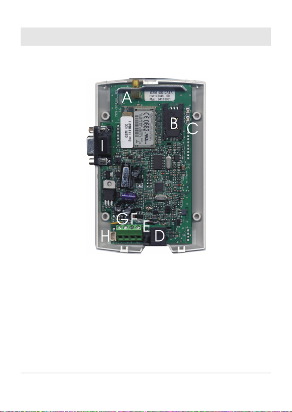
INSTALLATION
Remove the cover by pressing the upper side.
A ANTENNA cable connector
B SIM CARD housing with front panel
C LED indicating signal strength (green) and LED indicating device operation
status (red)
D Telephone line output (RJ11 connector) for telephone set connection or PABX
analogue line connection
E 230Vac external adapter input
F Telephone line output (terminal block) for connection of autodialer/PABX
analogue line
G 12Vdc power supply terminal block
H Backup battery connector (GC and DATA models only)
I RS232 port (DATA model only)
Page 7

Inserting the SIM card
Before inserting or replacing the SIM card, always make sure that the
gateway has been disconnected from the mains and that no electrostatic
discharge is present in order to avoid damaging it.
Take all necessary measures to avoid electrostatic discharge.
Shift the SIM card housing cover downward until it unblocks and
lift it.
Carefully slide the SIM card into its housing cover.
Lower the SIM card housing cover and shift it upward until it
blocks.
The SIM Card PIN must be DISABLED. If the PIN is
enabled, it must be disabled through a mobile phone.
WARNING
Inserting the antenna
Screw the antenna cable in to the connector on the top of the
module.
Do not install the product near other electric or
electronic devices that were not especially designed to
be used with it. They could be subjected to RF
interference from the module.
Page 8
WARNING

NEVER connect the GSM400 gateway without having
previously installed the antenna. The gateway may get
WARNING
damaged.
Connection to the telephone line
Connect the GSM400 to a standard telephone or to the PSTN input
terminals of a PABX or autodialer via the RJ-11 connector (D in the
picture at page 7);
or
Connect the GSM400 to a standard telephone or to the PSTN input
terminals of a PABX or autodialer using the TEL terminal (F in the
picture at page 7).
Connection to the power supply
Power supply via 230Vac external adapter
Connect the external adapter to the specific input (E in the picture
at page 7).
Connect the backup batteries (if present) to the dedicated input (H
in the picture at page 7).
Close the gateway cover.
or
12Vdc power supply
Connect the power supply cable to the terminal (G in the picture at
page 7) taking care to respect the polarity.
Connect the backup batteries (if present) to the dedicated input (H
in the picture at page 7).
Page 9

Close the gateway cover, paying attention to the power supply
cable.
Backup batteries, if present, may be connected only
WARNING
after GSM400 has been supplied
Note: the max voltage to be supplied to the mains terminal
G is 17Vdc.
Note: the min voltage required to supply the GSM400
gateway by the mains terminal G is 10Vdc.
Note: a protection cut-out switch must be installed upstream
to interrupt power supply in case of fault.
Turning the GSM400 gateway on
Power the GSM400.
Wait 15 seconds after power-up to give time to the GSM400 to
register correctly with the GSM network.
Make sure the red LED (device status) flashes briefly once every 3
seconds as shown in chapter “SIGNALS”.
Set parameters or make a call.
If the red LED flashes quicker and stays lit for a longer time (see
“SIGNALS”), the GSM gateway has not properly registered with the GSM
provider. Disconnect GSM400 and make sure the SIM card is inserted
correctly and that the PIN is not locking it.
Page 10
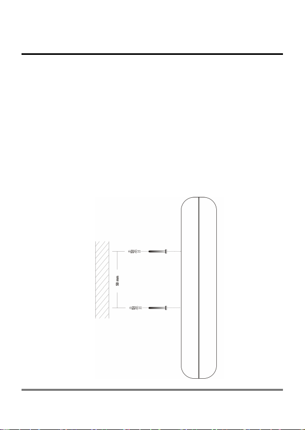
Gateway mounting operations
Check the GSM signal strength through the green indicator LED
(see “SIGNALS”) and identify an area where the signal is strong
enough.
Note: the signal strength may vary according to the
telephone provider.
Drill two holes with 5 mm diameter on the wall at a distance of 50
mm.
Insert the 2 fischers and screw down until the screws are at a 5
mm distance from the wall.
Place the GSM400 gateway onto the two screws through the two
back slots.
Page 11
GSM400 installation recommendations
The GSM400 gateway must be installed in a location where the radio
signal allows for using the GSM system.
It is advisable to leave plenty of space around the gateway for
maintenance operations.
Do not install the GSM400 gateway outdoors, since it lacks protection
devices against weather conditions that can damage the gateway (water,
humidity, etc.).
Do not install the GSM400 gateway near electronic (radio or TV sets,
Personal Computers, wired radio systems, etc.) or magnetic (credit
cards, floppy disks, etc.) devices that could be subjected to RF
interference from the module: recommended distance from the antenna
is min. 2.5 m.
Do not install the GSM400 gateway near medical devices. Its operation
may cause damage to hearing aids or pacemakers.
Always make sure that the device operation is permitted in the place of
installation (i.e. installation is not allowed in hospitals, airplanes, etc.).
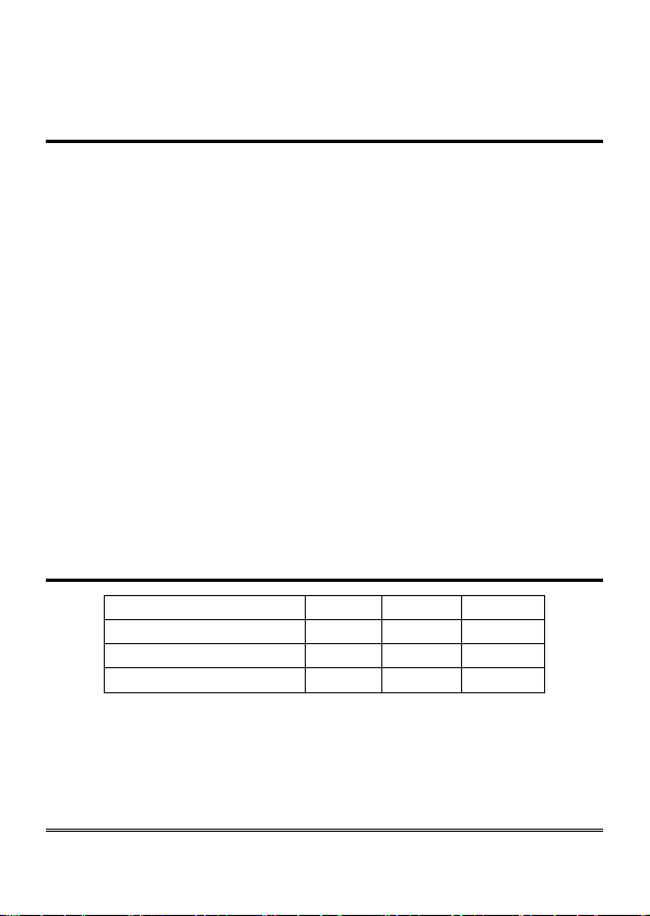
Absorption chart
Power supply 10Vdc 12Vdc 13,8Vdc
Telephone handset down 30mA 25mA 25mA
Telephone handset up 85mA 70mA 60mA
Conversation 160mA 130 mA 120mA
Page 12

PROGRAMMING VIA
TELEPHONE
Allows you to customise the gateway according to your requirements.
Programming can be carried out locally via a MF telephone.
You can programme:
voltage of telephone line;
use mode;
interdigit dialling time;
country calling code and international call prefix;
CLIP/CLIR settings;
roaming service settings;
notifications telephone number;
administrator telephone number ;
programming-mode password;
low-battery check;
automatic converter of selected telephone number;
receiver gain adjustment;
transmitter gain adjustment.
Note: during programming, the interdigit dialling time must
not exceed the time set during the “Interdigit dialling
time” programming. Once this programmed time has
elapsed you will hear the dissuasion tone and you will
have to hang up.
Note: at the end of each programming carried out correctly,
you will hear a confirmation tone, while an error tone
will be heard in case of error. In any case, the
dialling tone will follow, after which you can proceed
with the programming or make a call.
Page 13
Note: programming can be carried out even if the signal is
absent. After the confirmation or the error tones, the
“no signal” tone will follow, after which you can
proceed with programming or hang up.
VOLTAGE OF THE TELEPHONE LINE
The following programming allows you to modify the voltage in the TEL
terminal and in the RJ-11 connector. A higher voltage may be required
for the proper functioning of specific devices.
Factory default: lower voltage (36Vdc).
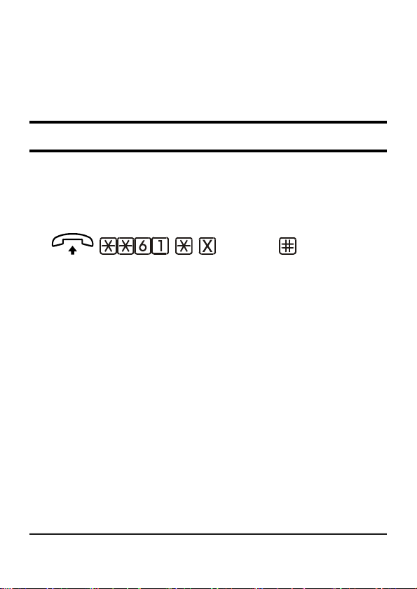
(option) (confirm)
Lift the handset and dial: **61*.
Enter:
0 lower voltage (36Vdc);
1 higher voltage (52Vdc).
Dial # to confirm.
After the confirmation tone hang up or enter additional settings.
Note: do not change factory default unless it is strictly
necessary.
Page 14
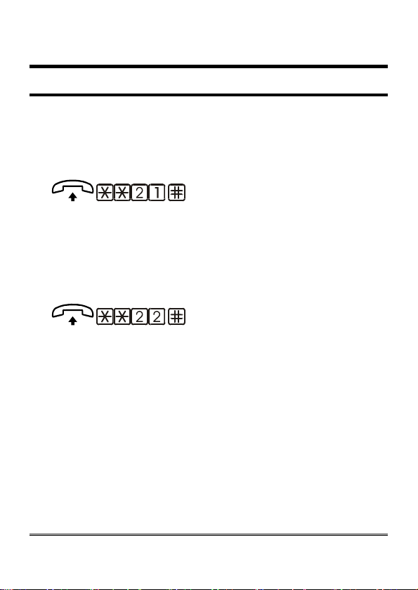
USE MODE
It allows to indicate whether the device is connected to the input terminals
of an autodialer or a PABX or directly to an analogue telephone set.
Factory default: telephone / PABX.
Setting telephone / PABX mode
(confirm)
Lift the handset and dial: **21.
Dial # to confirm.
After the confirmation tone hang up or enter additional settings.
Setting autodialer mode
(confirm)
Lift the handset and dial: **22.
Dial # to confirm.
After the confirmation tone hang up or enter additional settings.
Page 15
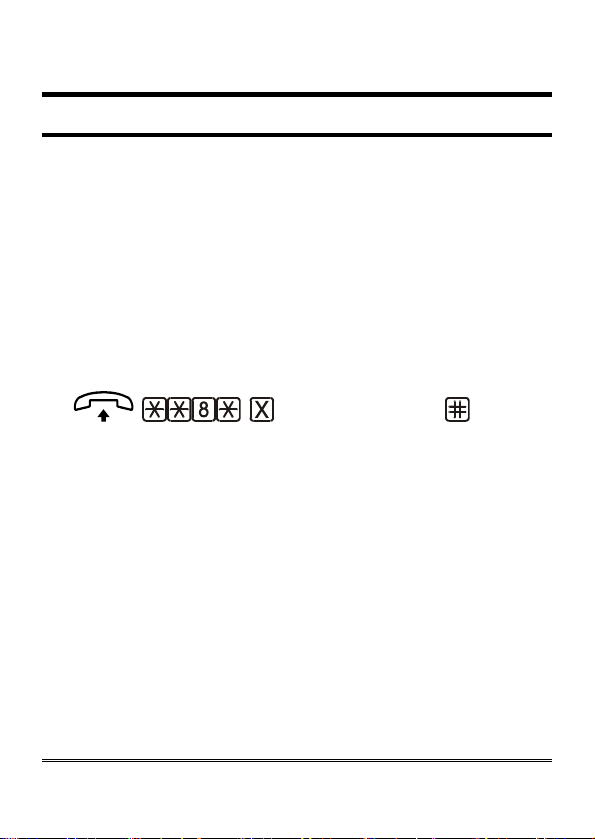
INTERDIGIT DIALLING TIME
The interdigit time is the maximum amount of time allowed between
digits while dialling a telephone number or a programming code.
There are 2 ways to make outgoing calls:
Dial the telephone number and then press # to confirm. The call is
sent immediately.
Dial the telephone number and wait. The call will be sent after the
interdigit time has elapsed.
If you wish to use the second way, it could be useful to modify the
interdigit time, in order to quicken the calling procedure.
Factory default: 5 seconds.
(interdigit time)
(confirm)
Lift the handset and dial: **8*;
Dial the interdigit dialling time:
0 interdigit time: 10 seconds;
1-9 interdigit time from 1 to 9 seconds.
Dial # to confirm.
After the confirmation tone hang up or carry on with other
programmings.
Page 16
DIALLING CODES
This programming is necessary for the correct operation of the caller
number display service (CLI). It allows displaying the caller’s telephone
number without the area code.
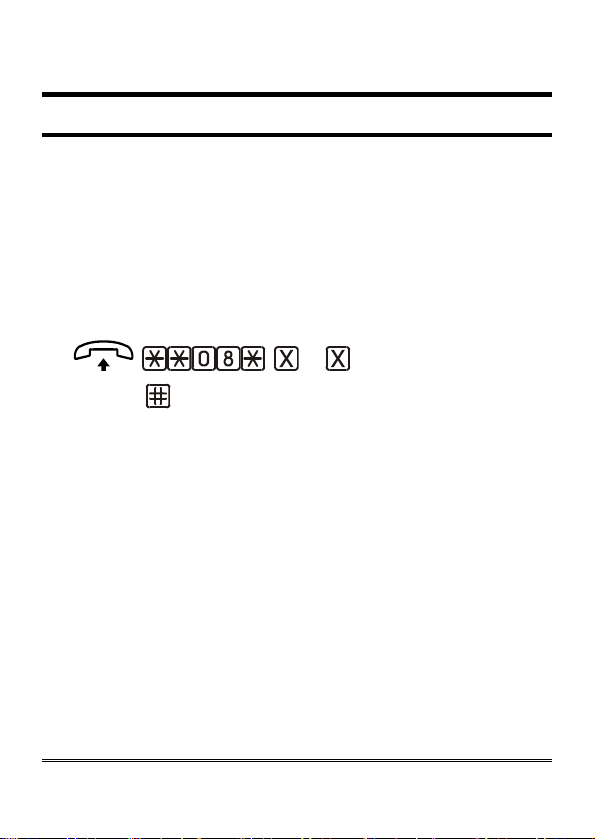
International call prefix
The international call prefix is the first part of a country’s code. For
example, the international dialling code for Italy, whose complete code is
0039, is 00.
Factory default:
prefix) (confirm)
Lift the handset and dial: **08*;
Dial the international call prefix (max. 5 digits).
Dial # to confirm.
After the confirmation tone hang up or carry on with other
programmings.
Country calling code
The country calling code is the second part of a country’s code. For
example, the
is 39.
Factory default: 39
00.
... (international call
country calling code for Italy, whose complete code is 0039,
.
Page 17
 Loading...