

Page 1
Operation and Installation Instruction
Fire Alarm Computer
8000C / M
Page 2

Safety
Intended purpose
This product must only be used for the applications outlined in the catalogue and the technical
description and in combination with external components and systems which have been
approved or recommended by ESSER.
Warning
In order to ensure correct and safe operation of the product, all guidelines concerning its
transport, storage, installation, and mounting must be observed. This includes the necessary
care in operating the product.
Safety-relevant user information
This manual includes all information required for the proper use of the products described here.
The term 'qualified personnel' in the context of the safety information included in this manual or
on the product itself designates:
• project engineers who are familiar with the safety guidelines concerning fire alarm and
extinguishing systems
• trained service engineers who are familiar with the components of fire alarm and
extinguishing systems and the information on their operation as included in this manual.
• trained installation or service personnel with the necessary qualification for carrying out
repairs on fire alarm and extinguishing systems or who are authorised to operate, ground
and label electrical circuits and/or safety equipment/systems.
Safety warnings
The following information is given in the interest of your personal safety and to prevent damage
to the product described in this manual and all equipment connected to it.
Safety information and warnings for the prevention of dangers putting at risk the life and health
of user and maintenance personnel as well as causing damage to the equipment itself are
marked by the following pictograms. Within the context of this manual, these pictograms have
the following meanings:
Danger of death, severe injury or considerable material damage if the relevant safety
!
precautions are not observed.
☞
Important information on the product or a particular section of this manual, which
should be read with particular attention.
Page 2
Fire Alarm Computer 8000C / M
Page 3

Table of Contents
1 General ....................................................................................................................................................4
2 General view............................................................................................................................................5
2.1 Key switch / enabling operation ............................................................................................................6
2.2 Function of the display and operating elements ..................................................................................7
3 Operating status of the fire alarm control panel...................................................................................16
3.1 Normal condition..................................................................................................................................16
3.2 Fire .......................................................................................................................................................16
3.3 Trouble .................................................................................................................................................17
3.4 CPU failure...........................................................................................................................................17
3.5 Disconnection ......................................................................................................................................18
3.6 Testmode .............................................................................................................................................18
4 Operation ...............................................................................................................................................19
4.1 Function keys / selection menu ..........................................................................................................19
4.1.1 Display / display control................................................................................................. 21
4.1.2 Display priority of the messages in the display ............................................................. 23
4.1.3 Info text / additional text and parameter display ............................................................ 24
4.2 Entering time/date ...............................................................................................................................25
4.3 Detector zones.....................................................................................................................................26
4.3.1 Switching on / resetting a detector zone ....................................................................... 26
4.3.2 Disconnect a detector zone........................................................................................... 27
4.3.3 Status of a detector zone .............................................................................................. 28
4.4 Detectors..............................................................................................................................................29
4.4.1 Switching on / resetting a detector ................................................................................ 29
4.4.2 Disconnect a detector.................................................................................................... 30
4.4.3 Status of a detector .......................................................................................................31
4.5 Controls................................................................................................................................................32
4.5.1 Switching on a control output ........................................................................................ 32
4.5.2 Disconnect a control output .......................................................................................... 33
4.5.3 Status of a control output .............................................................................................. 34
4.6 Common display of the status messages ..........................................................................................35
4.7 Delay and Verify ..................................................................................................................................36
4.7.1 Delay ............................................................................................................................. 37
4.7.2 Verify ............................................................................................................................. 37
4.8 Alarm counter ......................................................................................................................................38
4.9 Lamp test .............................................................................................................................................39
5 Service Level .........................................................................................................................................40
5.1.1 Primary loop functions ................................................................................................... 41
5.1.2 Sensor functions (loop) ................................................................................................. 43
5.1.3 Sensor functions (zone/detector) .................................................................................. 45
6 Installation Instruction............................................................................................................................47
12 Micromodule....................................................................................................................................... 107
24 Commissioning / Servicing ................................................................................................................ 145
Fire Alarm Computer 8000C / M
Page 3
Page 4

General
1 General
To equip buildings, facilities, commonly-frequented areas and working spaces with a fire warning
system can only be carried out economically and with reasonable propriety when correspondingly
well-founded safety concepts are developed and accordingly applied.
Wherever the highest requirements are made on a fire warning system, whether in small
commercial facilities or in industrial plants, the
Fire Alarm Computer 8000C / M
techniques and economy into practical reality. The modular design with different micro modules
and individual extension concepts allow the Fire Alarm Computer 8000C / M to be easily adapted
to special requirements. The Fire Alarm Computer 8000C / M represents the most modern
standard of fire warning technology. A reliable fire warning facility is guaranteed by the application
of "intelligent" fire detectors connected in an analog loop which is tolerant to short and open
circuits.
transforms safety
In this analog loop -
the esserbus
being configured into 127 individual detector zones can be connected with an overall cable length
of up to two kilometres. The esserbus
®
/
esserbus
®
is a two-wire line supplied and monitored at both ends in
®
-PLus
- up to 127 loop devices each capable of
ring topology. The Fire Alarm Computer 8000C / M automatically registers the wiring of the analog
loop and determines the logical addresses of the individual loop devices. A separate adjustment of
the addresses of the individual loop devices is unnecessary. Bei Systemen mit der
Ringleitung ist zusätzlich der direkte Anschluss von adressierbaren, busfähigen
PLus
Signalgebern möglich. Für diese, direkt über den
esserbus
®
-PLus
angesteuerten Signalgeber, ist
esserbus
®
keine weitere Spannungsversorgung erforderlich.
Subscribers in the esserbus
alarm modules (TAL) and the specially developed esserbus
These esserbus
®
transponders are loop devices with freely programmable inputs and outputs, for
®
are automatic and non-automatic intelligent fire detectors, technical
®
transponder input/output devices.
example for the activation and monitoring of external devices such as display panels, alarm
devices, door closers and other connected equipment.
Using the
essernet
®
safety network, 31 Fire Alarm Computer 8000C / M or other network
subscribers such as display and operating panels or alarm devices can be connected in a
homogenous network. Operation of the fire warning system, e.g. switching off a detector zone, is
possible from any fire alarm control panel or operating panel in the essernet
alarm, trouble, disconnection or other events are transferred to all subscribers in the essernet
can be accessed from any desired position. Data exchange can, according to the transfer rate, be
carried out either with a twisted pair or a LAN cable. The essernet
®
communications protocol
®
. Signals such as
®
and
guarantees reliable data exchange even if a short or open circuit occurs in the network.
-
These Operating Instructions are intended to aid you in the operation of the Fire Alarm Computer
8000C / M in addition to the description provided by the specialised installer and should be kept
together with the technical documentation of the fire alarm system. If you have any questions,
please consult your specialised installer.
The operation of an installed and operative fire alarm control panel may only be carried out by
authorised and trained persons under observance of the safety precautions and, if necessary, in
collaboration with other organisations (e.g. fire department).
Page 4
Fire Alarm Computer 8000C / M
Page 5

2 General view
1 5432
General view
Fire al arm
Disconn. / Trouble
Fire al arm
Disconn. / Trouble
Fire Pre-Alarm Trouble Disconnection
Releasi ng System
Master Box (MB)
Notify Fire Dept.
Detector
Fig. 1: General view of the display and operating elements
Delay
Verify
123
Zone
456
789
Relay
in Operation
CPU Failure
Power Supply
Relay Outputs
Master Box
Testmode
6
locked
7
8
On
Off
Test
Status
Panel
reset
Disconnect
Relay
Disconnect
Master Box
Additional
Messages
Delay
Verify
Buzzer off
unlocked
0
9
Single zone indicator units (GEA)
1
Common display FIRE
2
Common display PRE-ALARM
3
Common display TROUBLE
4
Common display disconnection
5
Alphanumeric display
6
Key switch
7
Operating elements
8
Function keys and keyboard
9
Fire Alarm Computer 8000C / M
Page 5
Page 6

Key switch / enabling operation
2.1 Key switch / enabling operation
Key switch in horizontal position
locked
unlocked
Fig. 2: Keyboard unlocked
♦ The keyboard is unlocked for the operation of the single Fire Alarm Computer 8000C / M and
other processors interconnected through the essernet
®
.
♦ The display menu is activated.
♦ If a fire alarm is activated, the activation of the master box (MB) is inhibited. (Works
adjustment - can be changed by client programming.)
In case of a fire alarm, activation of the master box (MB) will be disabled by the FACP.
!
The fire brigade will not be alarmed, automatically. In case of an event, the red LED Notify
fire department will be lit.
Key switch in vertical position
locked
unlocked
Fig. 3: Keyboard blocked
♦ The keyboard is blocked. The key can be removed.
♦ The keys Additional Messages and Verify / Buzzer off can still be operated when the keyboard
is blocked.
Page 6
Fire Alarm Computer 8000C / M
Page 7
Function of the display and operating elements
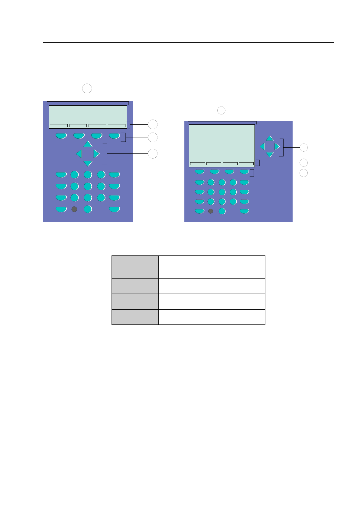
2.2 Function of the display and operating elements
The Display System 8000 is available with standard and ¼-VGA-Display.
1
1
2
3
4
123
Zone
456
Detector
789
Relay
0
On
Off
Test
Status
123
456
789
0
4
2
3
Fig. 4: Operating elements - keypad - display Operating elements - keypad - 1/4 VGA display
1
Alphanumeric display
standard or ¼ VGA display
2
3
4
Menu
Function key
Cursor key
All received signals such as fire, trouble or switch-off are shown in the alphanumeric display in
alphanumeric form (8 lines, 40 characters per line).
Keyboard
By means of the key switch, the keyboard is unlocked for operation. With these keys, it is possible
to control panel functions such as switching detector zones and detectors on and off.
Function keys
With the four function keys, the menu options positioned above them in the alphanumeric display
are selected. Depending on the current state of the fire alarm control panel or the operation level,
differing menu options are shown in the display.
Fire Alarm Computer 8000C / M
Page 7
Page 8

Function of the display and operating elements
Fire
Releasing System
Master Box (MB)
Notify Fire Dept.
Fig. 5: Common display fire
The common display Fire is activated if at least one fire alarm has been detected. The originating
detector or detector zone will be shown on the alphanumeric display.
☞
Fire
Red LED is permanently on
Fire Releasing System
Red LED is permanently on
Master box (MB)
Red LED is permanently on
If evacuation plans or guidelines exist for cases of fire alarm, these plans have to be
followed and the premises have to be evacuated, if necessary. Make sure to inform yourself
well in advance about existing escape routes and required measures in case of a fire.
Fire alarm !
⇒
At least one detector and / or one manual call point and / or a
loop is signalling a fire condition.
The fire releasing control equipment is been activated.
⇒
The master box (MB) is activated and the intervention staff
⇒
(e.g. fire department) has been alarmed.
Notify fire department
Red LED is permanently on
Page 8
Fire Alarm Computer 8000C / M
The master box (MB) has malfunctioned or is switched off and
⇒
cannot be activated. Call the fire department immediately !
Page 9

Function of the display and operating elements
Pre-Alarm
Delay
Verify
Fig. 6:Common display pre-alarm
In the Pre-alarm status, the master box (MB) is not activated to route the alarm to the assisting
bodies. A Pre-alarm is signalled when an intelligent fire detector reaches the pre-alarm level or
when in a programmed twin-loop/twin detector connection a loop or a detector have detected a fire
alarm. The controls programmed in the customer data for this situation such as relay outputs to
actuate alarm devices are activated.
The Pre-alarm is automatically reset if no further signals are transmitted. The common display Prealarm is extinguished and any activated alarm devices are switched off. If further alarm signals
occur, a fire alarm is automatically initiated and the master box (MB) is activated.
PRE-ALARM
Red LED is permanently on
Control actions assigned to this event by means of customer data programming, e.g. relay outputs
for activating internal signalling devices or evacuation signals will be executed.
☞
On pre-alarm, the master box for alarming the emergency services will not be activated.
At least one detector or detector zone is signalling the pre-alarm
⇒
condition.
The activated detector or the activated detector zone is
indicated on the alphanumeric display.
Fire Alarm Computer 8000C / M
Page 9
Page 10

Function of the display and operating elements
Delay
Yellow LED lights
Yellow LED blinks
Verify
Yellow LED lights
An on/off switching interval has been programmed for the delay
⇒
function.
During this time, the activating of the master box (MB) due to a
fire alarm is automatically delayed by the delay time
programmed in the customer data base.
An alarm signal has been detected during the active delay time
⇒
and the programmed delay time (max. 600 seconds, according
to programming) has been initiated.
The master box is activated after expiry of this time.
The function Verify has been activated by the Verify/Buzzer off
⇒
key. The programmed Verify time (max. 600 seconds) for the
Verify of the cause of the alarm is running.
The master box is only activated after the expiry of the Verify
time.
☞
The function delay/Verify is described in Section 4.7.
Page 10
Fire Alarm Computer 8000C / M
Page 11

Function of the display and operating elements
Trouble
in Operation
CPU Failure
Power Supply
Fig. 7: Common display TROUBLE
The common display Trouble is activated if at least one malfunction has been detected. The
reason will be shown on the alphanumeric display.
Yellow LED lights
Operation
Green LED is permanently on
CPU failure
Yellow LED is permanently on
A component of the fire alarm control panel or a monitored relay
⇒
output such as an external alarm device or a master box has
malfunctioned.
The power supply (battery or mains voltage) is connected. The
⇒
fire alarm control panel is in an operative condition.
The fire alarm control panel is only partially operative due to a
⇒
malfunction of the control panel functions. Display or operation
of the control panel is no longer possible (Exception: Key
Buzzer off).
The activating of the master box (MB) and the LED Master box
(MB) and Notify fire department is still operative in the CPU failure
mode of the control panel in the case of a fire alarm.
Power supply
Yellow LED is permanently on
☞
In cases of malfunction or emergency operation, correct functioning of the FACP is no
longer ensured. Inform customer/maintenance service!
The power supply (battery or mains voltage) is out of order.
⇒
Fire Alarm Computer 8000C / M
Page 11
Page 12

Function of the display and operating elements
Disconnection
Relay Outputs
Master Box
Testmode
Fig. 8: Common display Disconnection
The common display Disconnection indicates that at least one output, input, or other component of
the FACP has been disconnected. The disconnection will also be shown on the alphanumeric
display.
Disconnection (common display)
Yellow LED is permanently on
Outputs
Yellow LED is permanently on
Master box (MB)
Yellow LED is permanently
on
!
A switched off master box will not transmit an alarm signal in the case of an event !
Testmode
Yellow LED lights
At least one input/output - e.g. a detector zone or relay has
⇒
been switched off.
At least one relay output (AE) such as an internal control panel
⇒
relay or the control of an esserbus
switched off.
The master box (MB) is switched off, e.g. for servicing, by
⇒
enablement of the keyboard with the key switch.
A component of the control panel (e.g. detector zone) has been
⇒
set to Testmode for servicing and maintenance work.
®
transponder has been
!
Page 12
A detector zone in Testmode will not transmit an alarm in the case of an event.
Fire Alarm Computer 8000C / M
Page 13

Function of the display and operating elements
Fire al arm
Discon n. / Troub le
Fire al arm
Discon n. / Troub le
Fig. 9: Single zone indicator units (GEA)
Optical displays (LED) for a total of 64 detector zones may be integrated into the control panel of
the fire alarm computer 8000C / M. Fire is signalled by a red LED. Malfunctions and disconnections
are signalled by a yellow LED. There is a labelling field for each detector zone which can be
marked with the name of the zone or of the area monitored by this group of detectors.
Fire alarm
Red LED is permanently on
At least one detector and / or one manual call point in the
⇒
detector zone is signalling an fire alarm.
Red LED blinks
For the zone, which first signalled the fire alarm (initial alarm
⇒
detection).
Disconnection / Trouble
Yellow LED is permanently on
The detector zone is switched off. Switching detector zones
⇒
on/off see Section 4.2.
Yellow LED blinks
At least one detector of the detector zone has malfunctioned.
⇒
Inform customer/maintenance service !
Switched off or malfunctioning detector zones will not transmit an alarm in the case of an
!
event.
Fire Alarm Computer 8000C / M
Page 13
Page 14

Function of the display and operating elements
Panel reset
All detected fire alarms, detector zones, displays and technical
Panel
reset
alarm signals (TAL alarm) are cancelled and returned to normal
condition.
Audible Alarm off
The connected alarm facilities are switched on or off (toggle
Disconnect
Relay
function).
Disconnect Master Box
The activating of the master box (MB) is switched on or off (toggle
Disconnect
Master Box
Switched off alarm devices and master boxes will not transmit an alarm in the case of an
!
event.
function). Switch-offs are displayed visually in the Common display
disconnection field.
Page 14
Fire Alarm Computer 8000C / M
Page 15

Additional messages
Additional
Messages
Delay
Delay
Verify / Buzzer off
Function of the display and operating elements
Additional messages can be shown in the display.
The first and last message with the highest priority are shown in the
display approximately 20 seconds after the key was last pressed.
By pressing this key the next message of the same or next level will
be displayed. The key Additional Messages remains functional
when the keyboard is locked (key-operated switch)!
When this key is pressed, the delay time is enabled/disabled
(toggle function)
See Section 4.7 Delay/Verify.
Verify
Buzzer off
Verify
Start of the programmed Verify time up to the delay activating of
the master box.
The Delay/Verify function is explained in section 4.7.
Buzzer off
Acknowledgement of the control panel buzzer. This key remains
active when the keyboard is locked. The buzzer is reactivated in
the case of a further event.
Fire Alarm Computer 8000C / M
Page 15
Page 16

Operating status of the fire alarm control panel
3 Operating status of the fire alarm control panel
The current operating status of the fire alarm control panel 8000C / M is shown on the operating
panel. Six different operating conditions are possible:
3.1 Normal condition
The normal condition refers to an operative monitoring state of the control panel unchanged by
external influences.
♦ The green LED in Operation lights.
♦ No further displays or messages.
♦ The operating panel keyboard is locked by the key switch.
3.2 Fire
♦ The control panel is in alarm mode, i.e. it is signalling a fire alarm.
♦ The common display FIRE (red LED) lights.
♦ The master box (MB) has been activated.
♦ The internal control panel buzzer sounds.
♦ External alarm devices, e.g. acoustic alarm devices or control panel buzzers are activated.
♦ The zone which has detected the fire is shown in the display with the programmed additional
text.
♦ The red LED of the corresponding zone(s) lights in the single zone indicator units (optional). If
several zones signal a fire alarm, the red LED of the zone which first detected the fire blinks
(initial alarm detection).
♦ The red LED Master box (MB) lights when a master box for automatic transmission of the alarm
is connected and the fire department has been informed.
♦ Possibly, the red LED Notify fire department may light. The fire department has not been
informed via the master box.
Call the fire department immediately!
Page 16
Fire Alarm Computer 8000C / M
Page 17

Operating status of the fire alarm control panel
3.3 Trouble
The common display TROUBLE (yellow LED) lights and the control panel buzzer sounds
intermittently.
♦ At least one control panel function has failed!
♦ A message is shown in the display describing the failure/cause.
♦ The yellow LED of the zone in which the malfunction has possibly occurred blinks on the single
zone indicator units (optional).
Detector zones/relay loops or inputs/outputs will not signal an alarm in the case of an
!
event. Inform customer/maintenance service!
3.4 CPU failure
The fire alarm control panel is only partially operative!
♦ No messages on the alphanumeric display.
♦ No evaluation of information.
♦ No activation of external equipment such as alarm sounders.
♦ The master box and the Master box (MB) LED and Notify fire department will be activated
even in the control panel CPU failure mode.
A comprehensive operation of the fire alarm control panel is no longer provided. Call
!
customer/maintenance service immediately!
Fire Alarm Computer 8000C / M
Page 17
Page 18

Operating status of the fire alarm control panel
3.5 Disconnection
The normal condition of the control panel has been changed by an external influence.
Displays:
♦ The common display disconnection (yellow LED) lights
♦ Possibly, a further display in the Common display disconnection field may be signalled,
showing which components have been switched off, e.g. Relay, Master box (MB)
♦ The disconnection is reported in the display as a plaintext message.
♦ A switched off detector zone is indicated on the single zone indicator units (optional) by a
permanently lighting yellow LED.
Switched off detector zones, detectors and controls (AE) and other parts of the equipment
!
will not signal an alarm in the case of an event!
3.6 Testmode
The yellow LED Testmode lights. The Testmode mode of the control panel has been activated for
service and maintenance purposes:
♦ The function of detectors/detector zones is under inspection.
!
A detector zone in Testmode will not signal an alarm in the case of an event.
Page 18
Fire Alarm Computer 8000C / M
Page 19
4 Operation
Operation
The following section describes the most important operating actions for a single fire alarm control
panel 8000C / M. If several processors are connected in a network through the essernet
deviations from this description are possible. In this case, please ask your specialised installer.
☞
The operation of an installed and operative fire alarm control panel may only be carried out
by authorised and trained personnel under observance of the safety precautions and, if
necessary, in co-operation with the relevant emergency services (e.g. fire department).
®
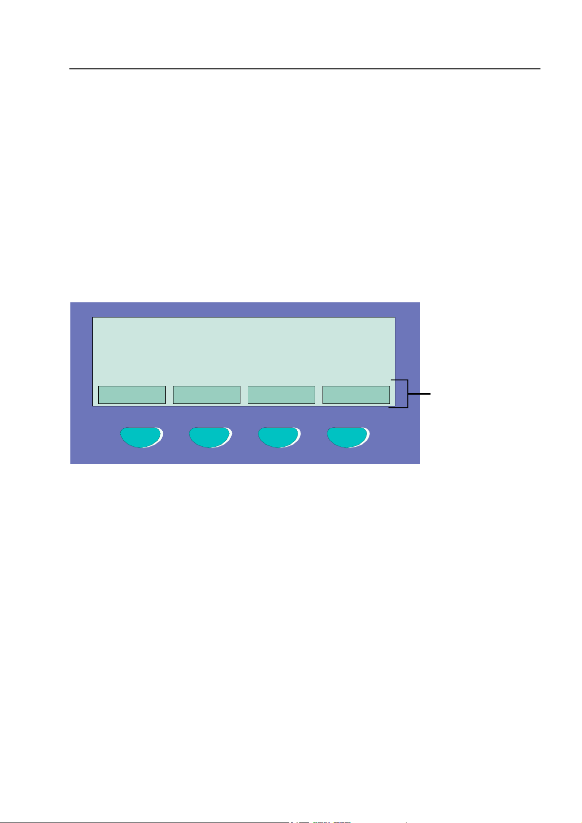
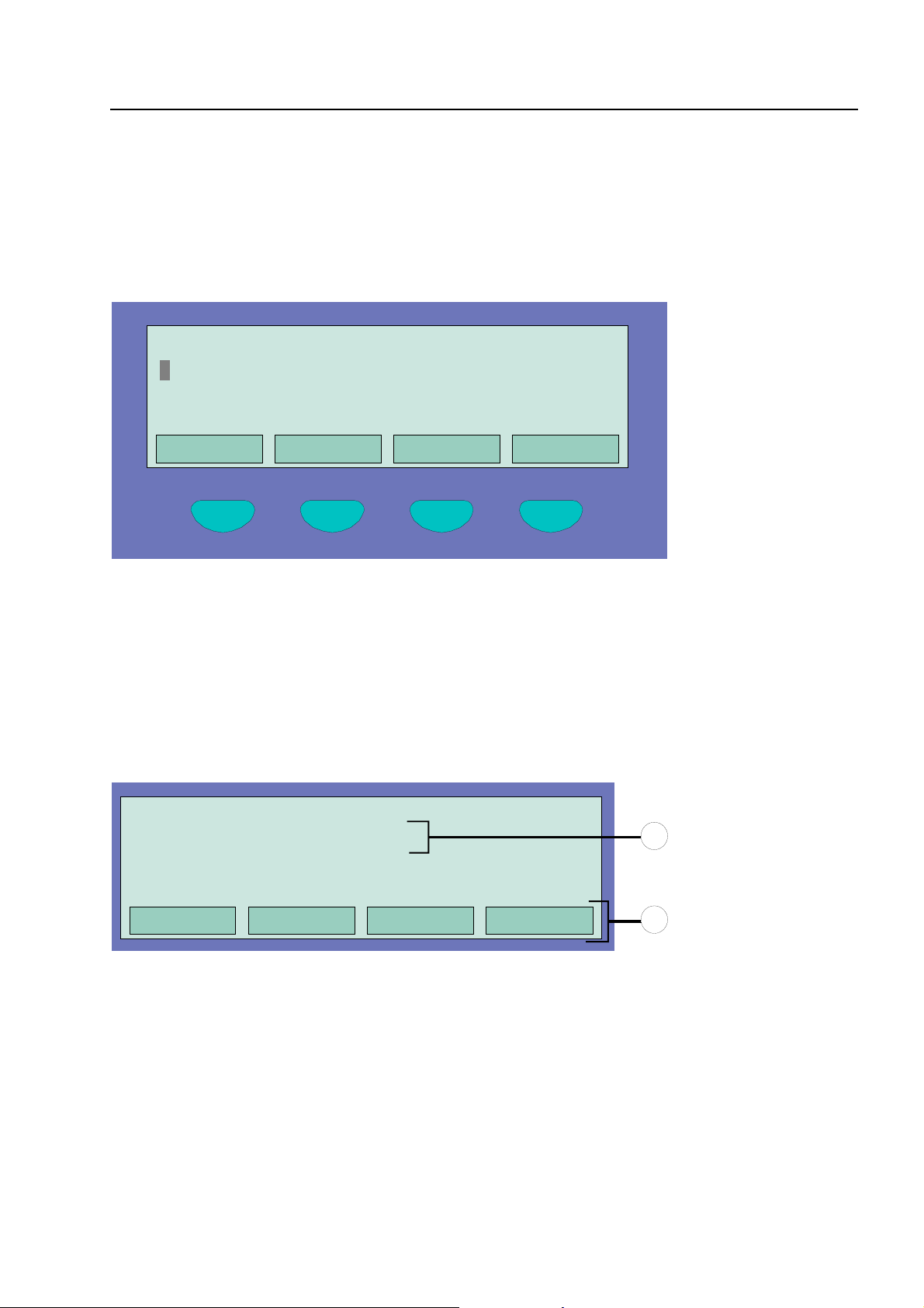
4.1 Function keys / selection menu
or param. / add. text
Overview Service Time func. Info
,
F1 F2 F3 F4
Fig. 10: Function keys / selection menu
Summary of the various menu options
The selection menu allows direct access to logically grouped menu options. When the keyboard is
unlocked, up to four menu options are constantly shown in the display, each of which can be
selected using the function key located below it.
Status
Summary
Service
⇒
⇒
⇒
Status display of current messages in order of significance.
Group display and number of the various types of message, such as fire,
trouble, disconnection etc.
Transfer to the service level to operate the primary loop functions such as
switching primary loops, sensors etc. on/off.
Fire Alarm Computer 8000C / M
Page 19
Page 20

Operation
Installer
Time funct.
Escape
Acknowledge
Function
Rem. text
Information and additional text
Info
Operating actions for the specialised installer for service and maintenance
purposes. (Individual password code required, if a code has been
programmed.)
Entry of time/date and the switching times of the Delay/Verify function.
Termination of the current input prompt without storing or executing the
function.
Acknowledge the selected menu point/operation.
Confirmation of the execution of the previously selected function.
Query of the additional text display (Remote text) of other fire alarm control
panels in the essernet
control panel in the essernet
control panel can be displayed by the remote text function on another fire alarm
control panel.
Display of any programmed information text relating to the message in the
alphanumeric display. If information text exists, i.e. has been programmed for
this message, the menu point Info is displayed. If info text has not been
programmed, the menu point Info is not displayed.
®
network. If an event has been detected by a fire alarm
®
, the additional text from the activated fire alarm
Param/AT
☞
If information or additional text has been programmed for a message, the additional text
(Param/AT) is always displayed first. Pushing the function key during the display of the
additional text shows the information text.
Display of the additional text programmed for the current message or a
parameter. For a parameter, a works-programmed information text for the
current message in the alphanumeric display is shown. It is possible to switch
from additional text/parameter display using the function key. If additional text
has not been programmed, the menu point Add. text is not displayed.
Page 20
Fire Alarm Computer 8000C / M
Page 21
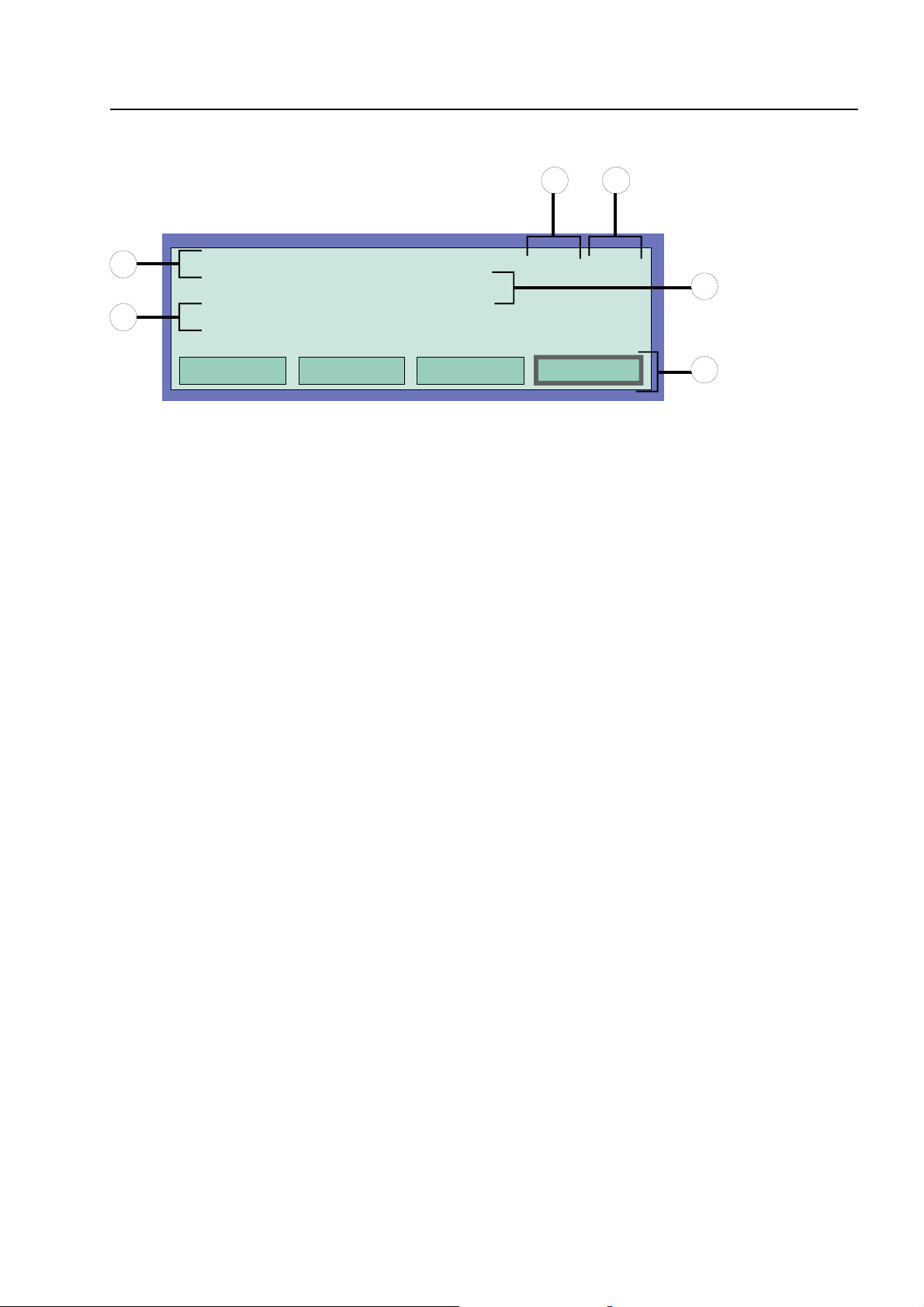
4.1.1 Display / display control
Display / display control
32
1
1
Fig. 11: Example display for a fire alarm (additional display)
1. FIRE Zone : 002 Det : 02 15:10 28:07
Office 1 Room 17 1st floor
3. FIRE Zone : 002 Det : 02
EDP room Room 21 1st floor
Overview Service Time func. Info
In all, three fire signals were detected. The display shows the first (1.) and the last signal
(in this case 3.) respectively. The display is scrolled by pressing the cursor key, and the
next signal (2.) is displayed.
Time of this alarm message
Date of this alarm message
Additional text line
(the additional text programmed for the triggered zone or detector will be displayed)
Additional information text or parameter / additional text (Param/AT)
4
15:10 28:07
5
Significance of the display to "1. Fire" :
♦ First fire signal on 28.07 at 15:10 hours.
♦ The detector No. 02 in the detector zone No. 02 signals FIRE.
♦ The additional text programmed for this detector zone "Office 1 Room 17 1st floor" provides
information on the location of the fire.
♦ The display field Info shows that an information text has been programmed for this detector
zone, which can be accessed by pressing the corresponding function key.
Fire Alarm Computer 8000C / M
Page 21
Page 22

Display / display control
1) First / last message with the next higher priority
2) A next message with equal priority
3) First / last message with the next lower priority
4) Prior message with equal priority
Fig. 12: Cursor keys
Further Displays / Messages
For your information, the following additional messages (if existing) are shown in the alphanumeric
display:
MB disconnected
MB trouble
Acoustic trouble
Acoustic disconnected
Revision active
when the activation of at least one master box (MB) for the warning of the
fire department has been switched off, e.g. by enablement of the
keyboard.
when at least one master box (MB) has malfunctioned.
when at least one acoustic alarm device has malfunctioned.
when at least one acoustic alarm device has been disconnected.
when the fire alarm control panel has been switched to revision on the fire
department operating panel.
Page 22
Fire Alarm Computer 8000C / M
Page 23

Operation
4.1.2 Display priority of the messages in the display
Additional
Messages
Fig. 13: Additional Message Key
Display priority
The first and last message with the highest current priority are shown in the alphanumeric display
of the Fire alarm control panel 8000C / M respectively. If several messages with equal priority are
imminent, these can be queried by pressing the key Additional Messages.
Priority stage Condition Display
1
2
3
4
5
6
7
8
9
10
11
12
Fire alarm
Fire alarm primary loop
Technical alarm
Pre-alarm
Trouble
Trouble primary loop
Transfer route switched on (Primary loop)
System trouble
Disconnection
Disconnection primary loop
Trouble relay output AE
Switch-off relay output AE
FIRE
FIRE
T-ALARM
PRE-ALARM
TROUBLE
LINE TROUBLE
LINE ON
SYS TROUBLE
DISCONNECTION
LINE OFF
TROUBLE
O/P OFF
☞
13
14
If the control panel is operated during the display, the corresponding function is carried out.
The message with the highest priority reappears in the display automatically approx. 20
seconds after the last key has been pressed.
Activate AE
Testmode
ACTIVATE
TEST
Fire Alarm Computer 8000C / M
Page 23
Page 24

Info text / additional text and parameter display
4.1.3 Info text / additional text and parameter display
1. FIRE Zone : 002 Det : 02 15:10 28:07
Office 1 Room 17 1st floor
2
1
Fig. 14: Info text display
Access via stairway right
Inform Mr. J. Smith (Tel. 02137 / 99152)
Status Param/*T
Info
Param/AT
Display of any programmed information text relating to the message in the
alphanumeric display. If information text exists, i.e. has been programmed for
this message, the menu point Info is displayed. If info text has not been
programmed, the menu point Info is not displayed.
Display of the additional text programmed for the current message or a
parameter. For a parameter, a works-programmed information text for the
current message in the alphanumeric display is shown. It is possible to switch
between additional text/parameter display using the function key. If additional
text has not been programmed, the menu point Add. text is not displayed.
If information or additional text and a parameter have been programmed for a message, the
information and additional text is always displayed first. Pushing the Param./AT function key during
the display of the additional text shows the parameter.
Example of an info text display (Fig. 14)
Access to programmed information text for this message programmed in the customer data and
related to the zones (max. 4 lines / 40 characters per line) can be attained by pressing the function
key Info.
In this example, the following two-line info text was programmed for detector zone 02 in a fire
condition:
Access via stairway right !
Inform Mr. J. Smith (Tel. 02137/ 99152)
Info text / additional text and parameter display
☞
Pressing the Condition function key returns the panel to the condition display. The display
switches automatically to the preceding menu point approx. 20 sec. after the last operation.
Page 24
Fire Alarm Computer 8000C / M
Page 25

4.2 Entering time/date
Time fct. Time/Date
Time
Date
Delay on
: 10:4
: Tu. 02.06.99
: --:-- off: --:--
Entering time/date
Escape
Fig. 15: Entering time/date
Year 2000 compliance
All functions of the Fire alarm control panel 8000 C/M work correctly in accordance with the
LPS2000 requirement. There is no action recommended on reaching the end date.
The end date of the implemented real time clock is the year 2080. After year 2080, leap
years will not be compensated and events will be displayed or printed with an incorrect date,
however time will remain accurate. Also any elements operated on specific dates or certain
days of the week will be actioned on the wrong day. The System 8000 C/M panel does not
incorporate any user codes that employ the calendar function to access or operate other
features.
Entering the time or the date is carried out under the menu point Time functions which is accessed
by pressing the corresponding function key.
The corresponding input field (hour, minute, day, etc.) is marked using the cursor keys and the
desired value is entered on the numeric keypad. When a date is entered DD.MM.YY, the day of the
week (Mo, Tu, We...) is automatically calculated.
Function
Escape
Function
Entering times for the function Delay/Verify; see Section 4.6 !
☞
Approx. 20 seconds after the last operating action, the display switches back automatically
to the last menu point without storing the changes/inputs !
⇒
⇒
Exits the menu point without storing the changes/inputs.
The numeric values shown in the display are stored.
Fire Alarm Computer 8000C / M
Page 25
Page 26
Detector zones
4.3 Detector zones
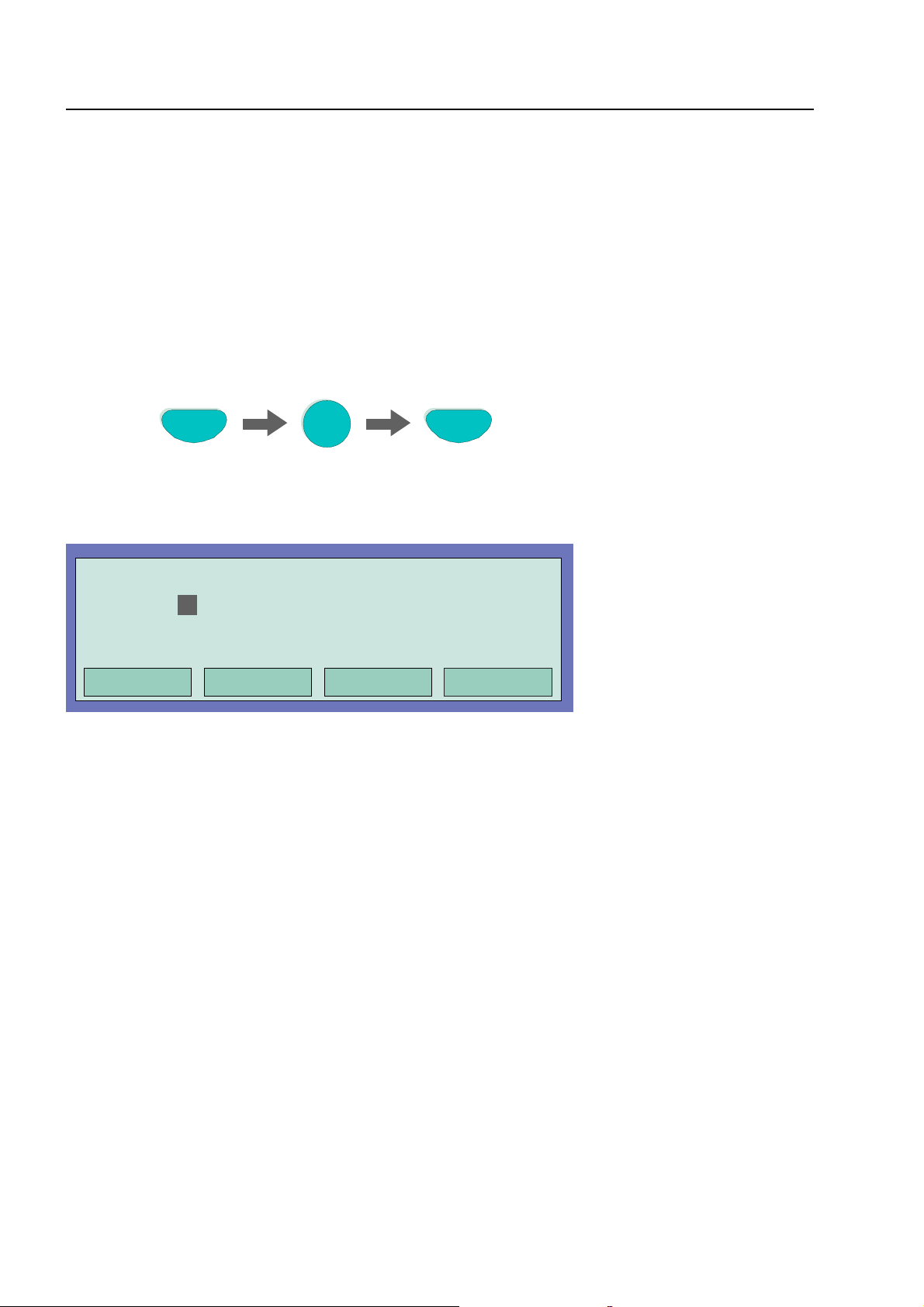
4.3.1 Switching on / resetting a detector zone
With switch-on/reset, a detector zone which has been switched off -incl. all fire alarms- is switched
into the operative status or an operative detector zone is reset and any imminent messages such
as Fire or Trouble are deleted.
Zone
Press Key
Fig. 16: Switching on / resetting a detector zone 4 (example)
Operation
Zone:
Detector: 0
Fig. 17: Display switching on zone 4
4
4
Off
in progress
On
Page 26
Fire Alarm Computer 8000C / M
Page 27
Detector zones
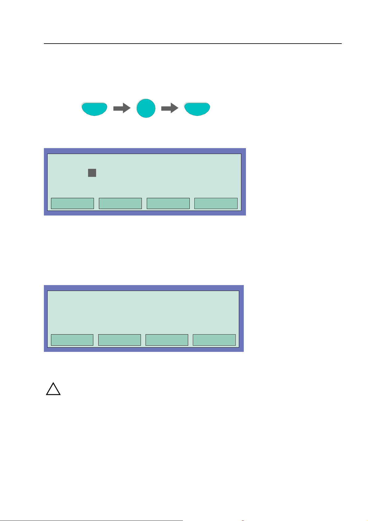
4.3.2 Disconnect a detector zone
With the disconnection, the corresponding detector zone -incl. all fire alarms- is disconnected.
The detector zone is selected by means of the corresponding zone number.
Zone
Press Key
Fig. 18: Switching off / resetting a detector zone 4 (example)
Operation
Zone:
Detector: 0
Fig. 19: Display switching off zone 4
In addition to the message on the display, the Disconnect is indicated optically by the common
display Disconnect on the control panel and the corresponding continuous lighting of the yellow
LED on the single zone indicator unit (if present).
4
4
Off
in progress
Off
1. Disconnect Zone: 0004 Det: 15
Additional text (client text)
Overview Service Time funct. Info
Fig. 20: Disconnect to status display
!
A disconnected detector zone will not signal an alarm in the case of an event!
11:10 22:11
Fire Alarm Computer 8000C / M
Page 27
Page 28

Detector zones
4.3.3 Status of a detector zone
With this function, the current status, e.g. Normal, Alarm and Trouble, of the corresponding detector
zone can be interrogated directly.
Zone
Press Key
Fig. 21: Status detector zone 2 (example)
Operation Zone : 0002
Status: normal
End
Fig. 22: Display Status zone 2
Status query
2
Page 28
Fire Alarm Computer 8000C / M
Page 29
Detectors
4.4 Detectors
Functions relating to detectors are only possible for addressable fire detectors of the ESSER
detector series 9100 and 9200. These fire detectors can be selected and controlled by a detector
address.
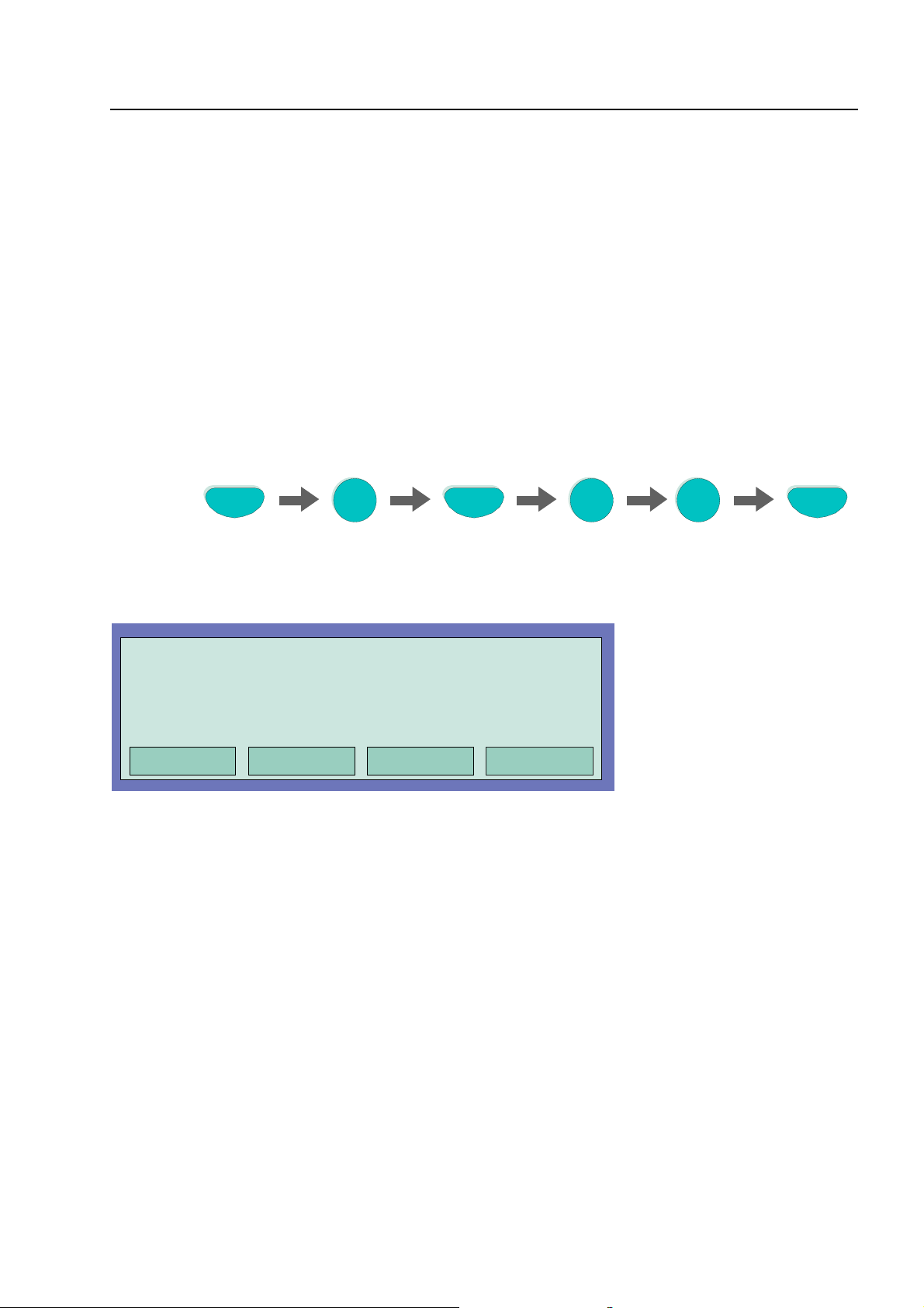
4.4.1 Switching on / resetting a detector
With switch-on, an individual disconnected detector of the selected detector zone is switched into
the operative status or an active detector is reset and any imminent messages such as Fire or
Trouble for this detector are deleted.
Please note that the zone number has to be entered before the detector number.
Zone
Press Key
Fig. 23: Switching on detector zone 2 /detector 12 (example)
Operation
Zone: 2
Detector: 12
Fig. 24:Display switching on detector zone 2 / detector 12
2 1
on
in progress
Detector
On
2
Fire Alarm Computer 8000C / M
Page 29
Page 30
Detectors
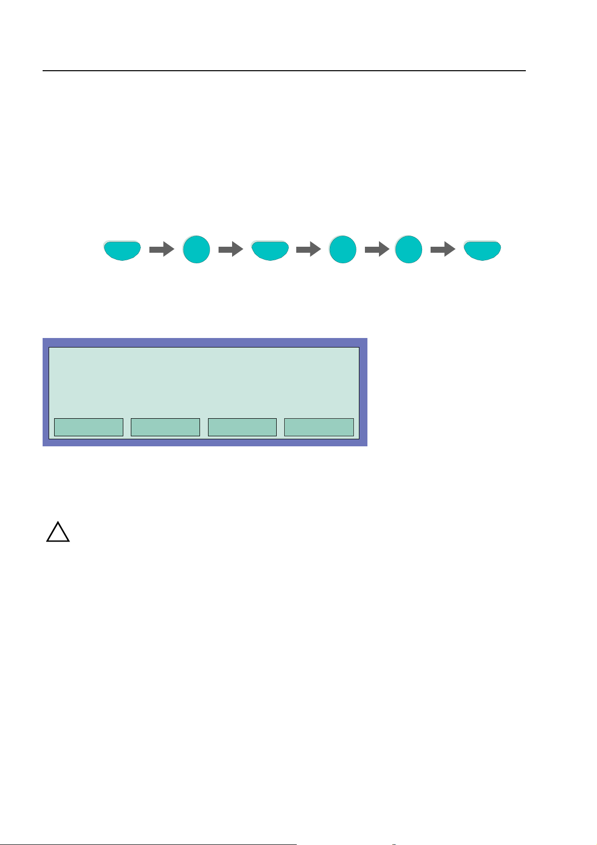
4.4.2 Disconnect a detector
With the disconnection, an individual detector of the selected detector zone is disconnect. In
addition to the message on the display, the disconnection of the detector is indicated optically in
the Common display Disconnect field.
Individual detectors within a detector zone can only be disconnected if addressable ESSER series
9100 and 9200 detectors are used. Series 9000 standard fire detectors can not be disconnected
individually.
Please note that the zone number has to be entered ahead of the detector number.
Zone
Press Key
Fig. 25: Disconnect detector zone 2 /detector 12 (example)
Operation
Zone: 2
Detector: 12
Fig. 26: Display disconnect detector zone 2 / detector 12
2 1
off
in progress
Detector
Off
2
!
Page 30
A disconnected detector will not signal an alarm in the case of an event!
Fire Alarm Computer 8000C / M
Page 31

Detectors
4.4.3 Status of a detector
With this function, the current status, e.g. Normal, Alarm and Trouble, of the corresponding
detector can be queried directly.
Individual status query within a detector zone is only possible if addressable ESSER series 9100
and 9200 detectors are used. Series 9000 standard fire detectors can not be queried individually.
Please note that the zone number has to be entered ahead of the detector number.
Zone
Press Key
Fig. 27: Status detector zone 2 /detector 12 (example)
Operation Zone : 0002 Det : 0012
Status: normal
End
Fig. 28: Display Status detector zone 2 / detector 12
2 1
Detector
Status query
2
Fire Alarm Computer 8000C / M
Page 31
Page 32

Controls
4.5 Controls
4.5.1 Switching on a control
With the switch-on, a previously switched off control (relay, open collector output) is switched back
on.
In case of an event, the switched-on output will be controlled in accordance with the programmed
control conditions.
Relay
Press Key
Fig. 29: Switching on Relay 2 (example)
Operation
Relay : 2
Fig. 30: Display switching on Relay 2
On
2
On
in progress
Page 32
Fire Alarm Computer 8000C / M
Page 33

Controls
4.5.2 Disconnect a control
With the disconnection, a control (relay, open collector) is disconnected. In addition to the plaintext
message in the display, the Disconnection of the control is indicated optically in the Common
display disconnect field.
Relay
Press Key
Fig. 31: Disconnect Relay 2 (example)
Operation
Relay : 2
Fig. 32: Display disconnect Relay 2
Relays may be set to inverse by means of customer data programming of the 8000C / M FACP. In
this case, the relays will be activated in the normal state of the FACP and deactivated in case of
the associated event.
2
Off
in progress
Off
If a relay for which inverse activation has been programmed is disconnected, it will be deactivated.
Control of external equipment depends on the way in which it is connected to the NO/NC contacts
of the relay.
The equipment connected to a disconnection control (e.g. alarm devices) are not activated
!
in the case of an event.
Fire Alarm Computer 8000C / M
Page 33
Page 34

Controls
4.5.3 Status of a control
With this function, the current status, e.g. Normal, Activated, Disconnection or Trouble of the
corresponding control can be queried directly.
Relay
Press Key
Fig. 33: Status Relay 2 (example)
Operation Relay : 0002
Status query: 0001 message
End
Fig. 34: Display status Relay 2
Status query
2
Relays may be set to inverse by means of customer data programming of the 8000C / M FACP. In
this case, the relays will be activated in the normal state of the FACP and deactivated in case of
the associated event.
In normal operation of the 8000C / M FACP, relays programmed for inverse activation are indicated
as 'active'.
Page 34
Fire Alarm Computer 8000C / M
Page 35
Common display of the status messages
4.6 Common display of the status messages
In the common display Overview, all current messages such as Fire, disconnection, Trouble and
other conditions of the fire alarm control panel are displayed, sorted by priority.
If more messages are imminent than can be shown in the display, it is possible to "scroll" in the
display with the cursor keys.
Overview 13:51 28:04
Fire
Switch-off
Switch-off AE
Status Service Time func.
Fig. 35: Display overview
For a detailed status display of a particular message, mark the corresponding message line with
the cursor and press the function key Status.
: 1 message
: 1 message
: 2 messages
Alarm counter
1. FIRE Zone : 002 Det : 02 14:10 28:04
EDP room, paper store
1
Overview
Fig. 36: Display for a detailed status message fire alarm (example)
Additional text line associated with the triggered zone/detector (example)
c
Additional information or parameters may be displayed by pressing function key Info.
d
Service Time func.
Info
Fire Alarm Computer 8000C / M
2
Page 35
Page 36

Delay and Verify
4.7 Delay and Verify
A switching time can be entered under this menu point Time functions by the operator of the fire
alarm system in addition to the switching times programmed under the Delay/Verify function in the
customer data (if programmed by the installer).
If a fire alarm occurs during the active delay function, the master box (MB) is only activated after
the expiry of the programmed delay time (max. 600 seconds). If the key Verify is pressed during
the delay time, the delay of the activating of the master box is extended by the verification time
programmed in the customer data (max. 600 seconds). The cause of the alarm can be verified in
this period.
After the expiry of the delay and the verification times, the master box (MB) is activated
automatically if the alarm state has not been cancelled and the activation of the master box
inhibited by pressing the panel reset key.
Time func. Time/Date
Time
Date
Delay on
: 10:42
: Tu. 02.06.99
:
:-- off: --:--
Escape Function
Fig. 37: Entering a switching point for the delay time
If a switching time for the function Delay/Verify has been programmed in the customer data by the
installer of the fire alarm system, the
accepted as the valid switching time when an additional switching time is entered under this menu
point Time functions. Exceptional days can be specified in the customer data programming on which
the automatic, i.e. delay/Verify times programmed by the installer will not take effect.
Example:
Customer data programming: Switch on
Operator's entry under this menu point: Switch on 10.00, switch off
Valid switching time: Switch on 06.30, switch off 15.00
first switch-on time and the first switch-off time
, switch off 21.30
06.30
15.00
is
☞
Page 36
Please consult your installer to find out whether the function Delay/Verify has been
programmed in the customer data of your fire alarm control panel. If this function is not
activated, e.g. for technical reasons or requirements, the functions described in this section
can not be used.
Fire Alarm Computer 8000C / M
Page 37

Delay and Verify
4.7.1 Delay
By pressing the Delay key, the function Delay is started or ended manually (toggle function). The
activated delay function is indicated on the operating panel by the continuously illuminated yellow
LED delay.
Delay
Fig. 38: Delay key
If a fire alarm occurs when the delay function is activated, the activation of the master box (MB) is
delayed by the delay time programmed in the customer data (max. 600 seconds). The initiated
delay time is indicated in the operating panel by the blinking yellow LED.
4.7.2 Verify
If the delay time has been started due to a fire alarm, the activation of the master box can be
delayed additionally to the delay time (max. 600 seconds) by the verification time (max. 600
seconds) for the Verify of the cause of the alarm by pressing this key.
Verify
Buzzer off
Fig. 39: Verify key
VdS
The guidelines of the Association of German Property Insurance Companys (Verband der
Schadenversicherer VdS, Cologne) must be observed for the function Delay and Verify.
Fire Alarm Computer 8000C / M
Page 37
Page 38

Alarm counter
4.8 Alarm counter
Differentiated display of the detected alarm signals from fire and technical alarm zones for this
individual fire alarm control panel and the aggregate value of all other fire alarm control panels
interconnected in the essernet
®
.
Alarm counter
Fire alarm : 6
Tech. alarm : 2
Sum : 50
Sum : 2
10:24 10:05
Overview
Fig. 40: Display alarm counter
Example display
6 Fire alarms and 2 technical alarms have been detected by this fire alarm control panel up to now.
The sum of all alarm signals detected in the essernet
technical alarms (TAL alarms).
☞
The alarm counter cannot be reset to -0000-.
®
network amounts to 50 fire alarms and 7
Page 38
Fire Alarm Computer 8000C / M
Page 39

Lamp test
4.9 Lamp test
The Lamp test function is activated for approx. 10 seconds to check the optical displays.
Test
Press Key
Fig. 41: Lamp test start
♦ All optical displays (LED) of the operating panel and the single zone indicator unit (if installed)
illuminate.
♦ The display area of the alphanumeric display is completely darkened.
♦ The control panel buzzer sounds.
♦ The versions No. of the panel software is then shown on the display.
This function ends automatically after approx. 10 seconds!
Pressing the Test key again stops the lamp test before the expiry of 10 seconds!
Fire Alarm Computer 8000C / M
Page 39
Page 40

Service Level
5 Service Level
The service level allows the operator to carry out operations or to switch off individual fire detectors
and primary loops in a functional fire alarm system. These functions can also be performed on
interconnected control panels integrated in the essernet
panel.
®
network, i.e. independently of the control
Overview
Fig. 42: Function key "Service“ in the status level
Service time func.
Service
1 Primary loop function
2 Sensor function (loop)
3 Sensor function (zone / det.)
Escape Installer Select
Fig. 43: Display in the service level
The following operations and switch-offs can be carried out in the service level on the fire alarm
control panel without entering an authorisation code:
♦ Primary loop functions (see Section 5.1.1)
♦ Sensor function (loop) (see Section 5.1.2)
♦ Sensor function (zone/detector) (see Section 5.1.3)
Enter the number of the desired function or select the menu point directly with the cursor keys and
press the Select function key.
The service level is protected from unauthorised access by means of an access code. Any
operation of the FACP may only be carried out by authorised and trained persons under
observance of the safety precautions and, if necessary, in cooperation with the emergency
services (e.g. fire department).
Page 40
Fire Alarm Computer 8000C / M
Page 41

Service Level
5.1.1 Primary loop functions
Using this function, primary loops including all connected zones and loop devices can be switched
on or off at the keypad.
The switching state is indicated on the control panel and the alphanumeric display.
Primary loop / Transfer route
Primary loop :
1 on / off
2 reset
Func. menu Repeat Select
Fig. 44: Entering the primary loop number
all analog loop modules included in this FACP
♦
(including the analog loop with all associated devices connected to this module)
all 4-zone-modules included in this FACP
♦
(including all detector zones and detectors connected to this module)
certain modules such as relays or the interface on the basic/peripheral module
♦
Switch on / disconnect Primary loops:
♦ Enter the number of the primary loop which is to be switched on and press the Select function
key
♦ Enter the number of the desired function (1 = switch on/reset, 2 = switch off) or select the menu
point with the cursor keys and press the Function key
In the case of an input error, the display can be erased by pressing the Zone key and the primary
loop number can be re-entered.
When a primary loop, for example a 4-zone module or an analog loop module is
!
disconnected, all zones and loop devices connected to this module are disconnected.
Disconnected fire detectors and call points will not activate an alarm in the case of an
event.
Fire Alarm Computer 8000C / M
Page 41
Page 42

Service Level
Example: FACP 8000C/M (Panel number 01)
Primary loop number 0113
Primary loop number 0123
Primary loop number 0131
B
2
1
2
1
B
3
D
4
5
Fig. 45 Example FACP 8000C Example FACP 8000M
Definition of primary loop numbers
Individual assemblies of the FACP 8000C/M can be switched on/off with the internal primary loop
number through the control panel keyboard or programmed with the customer data editor. This
internal primary loop number is composed of the control panel number, the slot and the assembly
number.
0 1 2 3
Subassembly number of the Basic-, Field deviceor extension module
Page 42
Slot number: Basic module = No. 1
Basic module Slot 1 = No. 2
Basic module Slot 2 = No. 3 (only 8000M)
Number of the Fire Alarm Panel (01 to max. 31)
Fire Alarm Computer 8000C / M
Page 43

Service Level
5.1.2 Sensor functions (loop)
Using this function, detector sensors of the multisensor fire detector such as all O sensors (Optical
= photoelectric sensor) or all I sensors (I = ionisation smoke sensors) or in OHI multisensor
detectors the OI sensor combination in an analog loop can be switched off.
Disconnecting sensors is only possible for OH and OHI multisensor fire detectors. These fire
detectors are fitted with two or three different sensors.
If, for example, OHI multisensor detectors are disconnected with the function OI sensors off, only the
third sensor - the H sensor (heat detector) - remains active. Disconnecting the heat sensors (H
sensors) is not possible.
Sensors (loop)
Primary loop :
1 O -Sensor off
2 OI-Sensor off
3 I -Sensor off
4 Sensors on
Escape Function
Fig. 46: Sensor functions reladed to primary loops
O detector
T detector
I detector
OT detector
OTI detector
⇒
⇒
⇒
⇒
⇒
Optical fire detector with a single sensor (photoelectric sensor)
Heat detector with a single sensor (Thermosensor)
Ionisation smoke detector with a single sensor (Ionisation sensors)
Multisensor fire detectors with two various sensors
(OT= Photoelectric and Thermosensor)
Multisensor fire detectors with three various sensors
(OTI= Photoelectric-, Thermo- and Ionisation sensors)
☞
Switching off sensors is only possible for OH and OHI multisensor fire detectors. If
multisensor fire detectors and standard detectors (detectors with a single sensor) are
installed together in an analog loop, only the sensor in multisensor detectors are switched
off.
Fire Alarm Computer 8000C / M
Page 43
Page 44

Service Level
Example of switching off sensors in an analog loop:
♦ Press key "2" to select the Service function (loop) or select the menu point with the cursor keys
and acknowledge by pressing the Select function key.
♦ Enter the primary loop number of the analog loop in which the sensors are to be switched off
and press the Select function key.
♦ Enter the number of the desired function (1 = O sensor off, 2 = OI sensor off, 3 = I sensor off,
4 = all sensors on) or select the function with the cursor keys and press the Function key.
☞
Switching on/off not permissible
The switching on/Disconnection of the detector sensors is indicated in the display.
If sensors have already been disconnected in an analog loop, for example I sensor off for all fire
detectors or if there are no sensors of the selected type in this analog loop or a zone disconnect
has been detected, the message "Switch on/Disconnect not permissible" is displayed.
In an analog loop, it is generally only possible to execute a disconnection function, e.g.
disconnected sensors or detectors, when no further, lower-order disconnected functions have been
carried out; i.e. when individual detector sensors within a detector zone have been disconnected,
this detector zone cannot be additionally disconnected, as disconnect functions for this detector
zone have been carried out. However, it is possible to switch off other zones of this analog loop in
which sensors/detectors have not been disconnected.
In order to change the existing sensor switching status, all disconnected detector sensors must first
be switched on, for example with the command All sensors on. After all detector sensors have been
switched on, a further switching off/sensor disconnect can be performed.
Switching off sensors is only possible for OH and OHI multisensor fire detectors. If
multisensor fire detectors with unifunctional detectors (detectors with only one sensor) are
installed together in an analog loop, only the sensors in multisensor detectors are switched
off.
Page 44
Fire Alarm Computer 8000C / M
Page 45

Service Level
5.1.3 Sensor functions (zone/detector)
Using this function, it is possible to switch off sensors in detector zones or in individual fire
detectors in an analog loop.
By entering the zone and detector number, individual sensors can be switched off in each single
multisensor detector.
If only the zone number is entered (detector number = 0), the desired sensor switch-off is
performed for all multisensor detectors in this detector zone. If sensors have already been
switched off in individual multisensor detectors in this zone, the message "Switch on/off not
permissible" appears. All sensors must first be switched on in this zone before the desired sensors
can be switched off.
(See also above Sensor function loop)
Sensors (loop)
Primary loop
Detector
:
:
1 O -Sensor off
2 OI-Sensor off
3 I -Sensor off
4 Sensors on
Func. menu Repeater Select
Fig. 47: Sensor function related to zones/detectors
☞
☞
Switching off sensors is only possible for OH and OHI multisensor fire detectors. If
multisensor fire detectors with unifunctional detectors (detectors with only one sensor) are
installed together in an analog loop, only the sensors in multisensor detectors are switched
off.
If a switch-off has already been performed, e.g. the sensors of a zone have been switched
off, this detector zone or the entire analog loop cannot be additionally switched off. It is
possible to switch off other detector zones of this analog loop in which detectors or sensors
have not been switched off.
Fire Alarm Computer 8000C / M
Page 45
Page 46

Notes
______________________________________________________________________________
______________________________________________________________________________
______________________________________________________________________________
______________________________________________________________________________
______________________________________________________________________________
______________________________________________________________________________
______________________________________________________________________________
______________________________________________________________________________
______________________________________________________________________________
______________________________________________________________________________
______________________________________________________________________________
______________________________________________________________________________
______________________________________________________________________________
______________________________________________________________________________
______________________________________________________________________________
______________________________________________________________________________
______________________________________________________________________________
______________________________________________________________________________
Page 46
Fire Alarm Computer 8000C / M
Page 47

Installation Instructions
Fire Alarm Computer 8000C / 8000M
from Version V2.41
Page 48

T
able of Contents
6 Installation Instructions......................................................................................................................... 49
6.1 Standards, guidelines and instructions for installation.......................................................................49
6.2 Standards and guidelines................................................................................................................... 50
7 Overview...............................................................................................................................................51
7.1 esserbus
7.1.1 Signalgeber für den esserbus
®
-PLus function.................................................................................................................... 52
®
-PLus...........................................................................53
7.2 Configuration options FACP 8000C................................................................................................... 55
7.3 Configuration options FACP 8000 M..................................................................................................58
8 Assembly...............................................................................................................................................63
8.1 Wallmounting ......................................................................................................................................64
8.1.1 Connection between the central housing and the extension housing ..........................66
8.2 Central housing...................................................................................................................................67
8.3 Mounting the cabinet / Installation...................................................................................................... 69
8.4 Extension housing............................................................................................................................... 72
8.5 Extension housing for two rechargeable batteries (789300/01)........................................................74
8.6 Operating module / housing door.......................................................................................................75
8.6.1 Opening and closing the housing door........................................................................ 75
8.7 Definition of the Primary loop number................................................................................................ 76
9 Power supply module (standard / esserbus
®
-Plus)............................................................................ 78
10 Basic module of the FACP 8000C / M................................................................................................. 82
10.1 Mains connection............................................................................................................................ 85
10.1.1Protective Earth - FACP 8000 C ................................................................................86
10.1.2Protective Earth - FACP 8000 M................................................................................ 87
10.2 Connecting the micro module......................................................................................................... 88
10.3 Serial interface.................................................................................................................................89
10.4 Common trouble relay ....................................................................................................................90
10.5 Inputs IN1 and IN2.......................................................................................................................... 90
10.6 Connection of the cover contacts...................................................................................................91
10.7 DIL switch S5 ..................................................................................................................................92
10.8 Reset-Function................................................................................................................................ 92
10.9 Connecting the built-in printer......................................................................................................... 93
11 Field device module..............................................................................................................................94
11.1 Connection of the micro module..................................................................................................... 97
11.2 Primary loop input Pri+/Pri-............................................................................................................. 97
11.3 Connecting a fire department operating panel............................................................................... 98
11.4 Connecting the master box (Relay K1).......................................................................................... 99
11.4.1Connecting the Relays K2, K3, K4........................................................................... 102
12 Extension module (Part no. 772419)................................................................................................. 104
13 Extension module (Part no. 772421)................................................................................................. 105
14 Configuration of the FACP 8000C / M with customer data editor.................................................106
15 Technical Data....................................................................................................................................107
Page 48
Fire Alarm Computer 8000C / M
Page 49

!
c
.
r
s
Installation Instruction
6 Installation Instructions
The terminal assignment and wiring illustrated in these installation instructions refer exclusively to the
facilities of the operating system software for the Federal Republic of Germany [D].
Operation of the f ire alarm control panel 8000C/M is governed by the national version of the operating
system software used and the country version programmed in the customer data.
6.1 Standards, guidelines and instructions for installation
S
The fire alarm panel may only be installed in a dry, clean room with controlled access and
appropriate lighting. T he environmental conditions must comply with IEC 721-3-3:1994, class
3k5.
S
The panel must be mounted on a flat surface using appropriate hardware (screws and dowels).
Avoid mechanical stressing. It may only be commissioned aft er correct mounting on a wall or
other mounting surface of sufficient streng t h t o support the weight of the unit.
S
Avoid strong electric or magnetic fields as well as mechanical influences. This applies
especially to the presence of fluorescent lighting or energy cabling in the close vicinity of the
panel, its components and the associated cabling. Do not mount on vibrating, unstable
surfaces such as light partitioning walls.
S
Do not install the system in places where adverse conditions prevail. Parts and components of
the system may only be installed in or led through locations which allow compliance with DIN
VDE 0800.
S
Connect the FE (functional earth) and PE (protective earth) terminals of the panel’s cabinet
with the PE rail of the power distributon panel from which the fire alarm system will be
powered.
S
Control panels and visual indicators mounted on a wall should be installed at a height of 800 to
1800 mm above the floor.
S
The fire alarm system is not suited for connection to IT power supply systems.
Danger – Electrical shock !
Remove all power from the panel before carrying out any installation work!
ESD protection
While handling electronic assemblies, the necessary precautions against electrostati
discharge must be taken.
Protective and functional earth
The PE conductor must be connected to the corr esponding terminal at the mains supply
Connect the FE terminal of the panel’s cabinet with the PE rail of the power distributo
panel from which the fire alarm system will be powered.
Fire Alarm Computer 8000C / M
Page 49
Page 50

I
nstallation Instructions
6.2 Standards and guidelines
The general technical rules must be observed when installing fire alarm systems. Any deviation
from those rules is only admissible if the same degree of safety can be ensured with different
means. Installations within the European Community are primarily subject to all EU regulations
defining the current standar ds for security systems.
In Germany, systems are considered to be in compliance with the general technical rules or the
standards of the EU f or security systems if they meet the technical guidelines of the VDE (Verband
Deutscher Elektrotechniker, Association of German Electrical Engineers). They may also be
considered to be in compliance with the standards of the EU f or security systems if they meet the
technical guidelines of another compar able institution within the European Community which have
been accepted in accordance with directive 73/23 EEC of the Council dd. 19 February 1973 –
directive on low-voltage systems- (ABL. EG No. L 77 page 29).
These are examples:
S
DIN VDE 0100 Installation of power systems with nominal voltages up to 1000 Volt
S
DIN VDE 0105 Operation of power installations
S
DIN VDE 0108 Installation and operation of power installat ions in com m unal facilities
S
DIN VDE 0185-103 Lightning protect ion systems
S
DIN VDE 0701 Repair, modificat ion and testing of electrical household appliances and similar
equipment
S
DIN VDE 0800 Telecommunications
S
DIN VDE 0815 Installation cables for communication and data processing systems
S
DIN VDE 0833 Hazard detection systems
S
DIN 14675 Fire alarm systems
S
DIN VDE 0845 Protection of telecommunication systems against lightning, electrostatic
discharges, and surge fr om electric power installations
These technical guidelines must be observed within the European Community. The VDE
guidelines must be observed within Germany. In other countries (e.g. U.S.A.: NFPA and UL
requirements), the r elevant national st andards, guidelines and legislation must be observed.
In addition to the above, the guidelines of the German VdS Schadenversicherer GmbH,
Association of German Property Insur er s ) m ay apply for system s inst alled in Germany.
These are e.g.:
S
VdS 2046 Safety rules for electrical power systems with voltages up to 1000 V
S
VdS 2015 Electrical appliances and systems – rules for damag e pr evention
S
VdS 2095 Design and installation of fire alarm systems
Page 50
Fire Alarm Computer 8000C / M
Page 51

essernet module 500K
essernet module 62,5K
RS 232/TTY-module
analog ring module
BSL-Interface m
odule
4-Output-module
7-Output-P-module/
7-Output-M-module
master box module
4-relay module
3 relay module
3 relay common
trouble module
4 zone module
123456789
0
w
Overvie
7 Overview
In full configuration, the FACP 8000C / M will accommodate up to two micro modules in any
configuration (also refer to Section on
basis card of the 8000C / M FACP. A second micro module slot may be added by inserting t he
appropriate peripheral or extension module.
Individually adaptable extension variants are possible with the freely selectable extension to the
FACP 8000C / M. The Field device modules required in order t o construct an individual central unit
in line with the relevant standards. The connections for the fire service control panel, the
transmission unit and the three freely programmable group relays are integrated on the Field
device module. If several fire alarm cent ral units are connected together in the essernet
service control panel can be connected to one of the other fire alarm central units.
micro modules
). One micro module slot is located on the
®
, the fire
Fig. 1: Micro modules of the Fire alarm system 8000
FACP 80000C
By installing a Field device module or extension module, the
compact, single-loop panel with an essernet
®
connection or a non-network, single panel with two
FACP 8000C
analog loops. W ith the installation of two analog ring modules, the expansion of an inexpensive
fire alarm contr ol panel with up to 254 bus subscribers, e.g . fire alarm or esserbus
can be expanded to a
®
transponders
and a total of 254 analog detector zones is possible.
FACP 80000M
With
FACP 8000M
®
7 esserbus
or 4 esserbus®-PLus loops is possible. This config uration can be made compatible,
almost without limitations, to the demands of individual sites with the use of use of bus devices
such as esserbus
, as well as the above functions, expansion to a high-perform ance system with
®
transponders. Up to 32 esserbus® transponders can be configured in a sing le
group on an analog loop.
Fire Alarm Computer 8000C / M
Page 51
Page 52
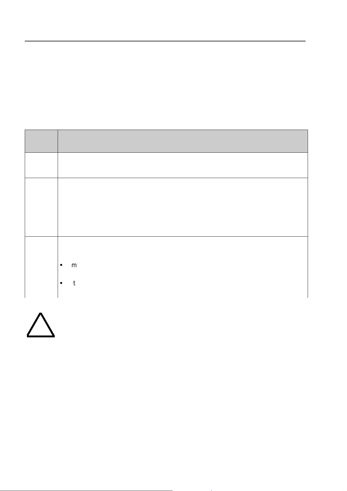
!
.)
o
O
verview
7.1 esserbus®-PLus function
The esserbus®-PLus analog loop micromodule (part no. 804382) operates special audible alarm
devices which are directly connected to the analog loop. In this application the hig her loop voltage
42 VDC in case of an alert is provided by the Power supply module (part no. 802426)
The esserbus
supply is not necessary
Required components for the esserbus
Part no. Description
-/- Basic module with Hard- and Softwareindex from Version V2.40 (or higher)
®
-PLus audible alarm devices are powered by the analog loop and an external power
®
-PLus analog loop:
802426
Power supply module with selectable 27,5 /42 V loop voltage
®
27,5 V => for esserbus
or
42 V => for esserbus
®
-PLus
804382 Analog loop module for esser bus®-PLus connection.
S
max. 4 analog loop modules per Fire alarm contr ol panel
S
It is only permitted to connect suitable devices for the higher loop voltage
(42 V DC) with part number
80xxxx
to the esserbus®-Plus loop.
Damage to the system !
It is only possible to operate the esserbus
®
-PLus devices compatible with the higher
loop voltage (42 V DC). Mixed operation of Standard and esserbus
within one panel is not possible !
Loop devices compatible with esserbus
are identified by the part number
80xxxx
®
-PLus, (transponders. detectors MCP´s etc
. These devices are also fully compatible t
the existing devices with part no. 78xxxx and may be used in standard esserbus
installations.
®
-PLus function
®
Page 52
Fire Alarm Computer 8000C / M
Page 53

p
16141210864204842363024181260Cable length
(806280/84)
Alarm sounder
(806282)
Base sounder
2000m
1600m
1500m
1300m
1100m
1000m
800m
700m1900m
Example 2: 2 Alarm sounders 900m cable length and 36 Base sounders
Example 1: 8 Alarm sounders 1300m cable length and 9 Base sounders
w
Overvie
7.1.1 Audible alarm devices for esserbus®-PLus
The following alarm devices are available for direct connection to the esserbus®-PLus analog loop:
Part no. Description
806280 (white)
806284 (red)
addressable Alarm sounder Series 9200
The total number of alarm sounders depends on the cable length. Max. 16 Alarm
sounders on one analog loop up to 700m reducing to max. 8 a l arm sounders up to
a cable length of 2000m (∅ 0,8 mm), see calculation diagram.
806282 addressable Base sounder module (with integrated detector base)
The total number of base sounders depends on t he cable length. Max. 48 base
sounders on one analog loop up to 700m reducing to max. 24 base sounders u
to a cable length of 2000m (∅ 0,8 mm), see calculation diagram
Combined operation of the Alarm sounder and Base sounder module is possible on one
esserbus
®
-PLus loop. The number of each type that can be installed and the eff ect of loop length
is defined in the following diagram .
Example 1
Example 2
Observe scale range!
n
Fig. 2: esserbus®-PLus calculation diagram for number of audible alarm devices / loop length
Calculation Diagram
The straight line for alarm sounder, cable length and Base sounder must be inside the grey
marked area in the Calculation Diagram . Cables below 700m should be treat as same as a leng th
of exact 700m.
Fire Alarm Computer 8000C / M
Page 53
Page 54

O
verview
Connection capabilities and field device of the Fire Alarm System 8000
F e u e r w e h r b e d i e n f e l d
L C D - A n z e i g e t a b l e a u
P a r a l l e l T a b l e a u
F S D
Ü E
T A L - B a u s t e in
m a x . 1 k m
8 0 0 8
e x t e r n e G e r ä t e
®
e s s e r b u s
-
K o p p l e r
®
e s s e r b u s
- P L u s
8 0 0 0 C
!
" # $
% & '
e x t e r n e G e r ä t e
e s s e r n e t
â
m a x . 1 k m
L i c h t w e l l e n l e i t e r
( L W L )
L W L
R e p e a t e r
m a x . 1 k m
L W L
E l e k t r o n i s c h e
E i n s a t z d a t e i
8 0 0 7
m a x . 2 k m
8 0 0 0 M
®
P r o z e s s a n a l o g m e l d e r S e r i e 9 2 0 0
B r a n d m e l d e - u n d
L ö s c h c o m p u t e r 8 0 1 0
e s s e r b u s
O u t p u t
K o p p l e r
e s s e r b u s
®
-
e s s e r b u s
K o p p l e r
I n p u t
®
-
Fig. 3: Overview Fire alarm system 8000 with esserbus®-PLus and essernet®
G r e n z w e r t m e l d e r g r u p p e n
z . B . S e r i e 9 0 0 0
D i a g n o s e m e l d e r g r u p p e n
z . B . S e r i e 9 1 0 0
Page 54
Fire Alarm Computer 8000C / M
Page 55
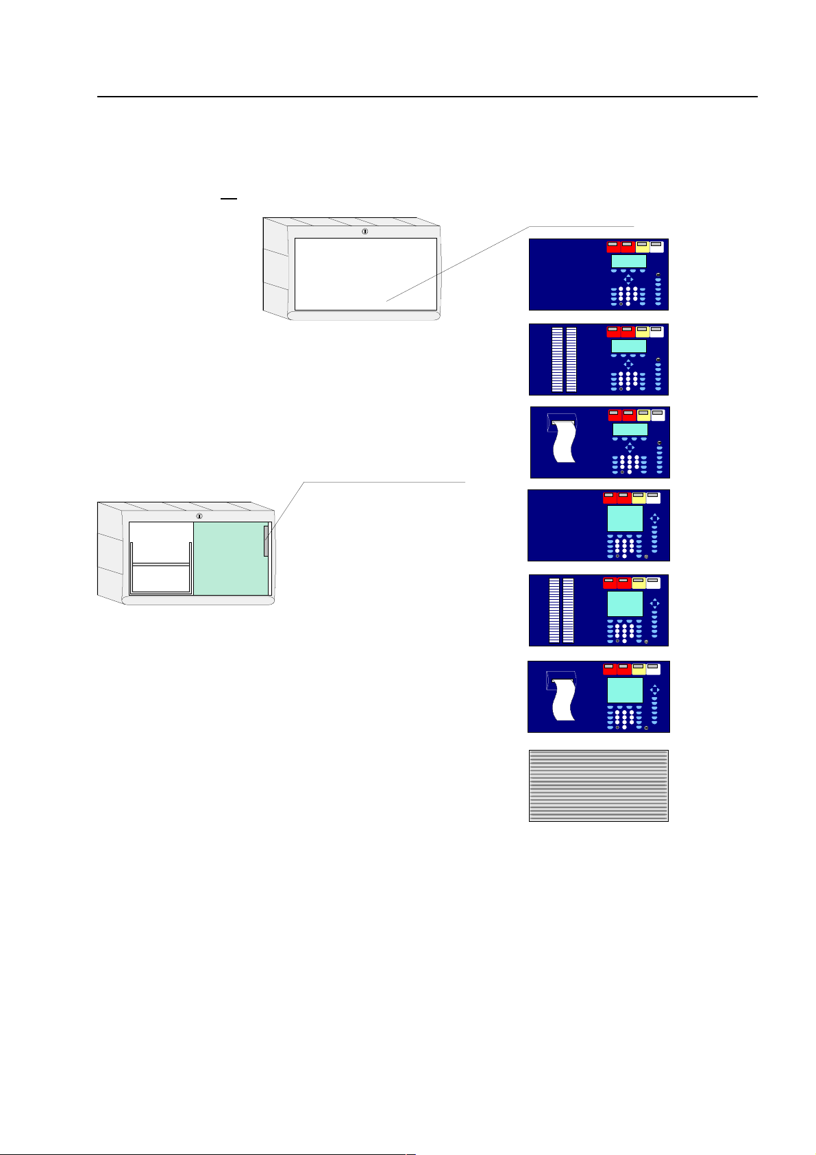
7860 _ _ or
7861 _ _ or
7868 _ _ or
Field device module 772420
772418
772419
7864 _ _ or
7865 _ _ or
742100
Plug 1
7869 _ _ or
C
Configuration options FACP 8000
7.2 Configuration options FACP 8000C
The FACP 8000C can be configured in dif ferent variations. T he operating module front (7860_ _)
is available in various language versions. The language is def ined with the two digits of the part
number, e.g. 786002
= English lettering.
Fire Alarm Computer 8000C / M
Page 55
Page 56

Basic module
and
power supply module
battery bag
Power supply module
ABC
Basic module
A
B
C
C
onfiguration options FACP 8000C
The complete expansion of the FACP 8000C includes a basic module, the power supply module
and a field device module with additional slots for micro modules. In the full configuration, two
freely selectable micro modules can be employed.
On the basic module of the FACP 8000C, only the upper slot (slot 1) can be used for a field device
or extension module. The lower slot (slot 2) of the FACP 8000C is not used.
Plug 1
Fig. 4:Configuration options (FACP 8000C)
Field device module Part No. 772420
Field device module with one micromodule slot Part No. 772418
Extension module with one micromodule slot Part No. 772419
Additional devices
The panel configuration may be extended by additional In-/Output modules (esserbus
transponders). It is possible to install these transponders inside t he panel housing (depending on
available space) or remote from the panel together with available mounting boxes (IP-rating 50).
®
-
Page 56
Fire Alarm Computer 8000C / M
Page 57
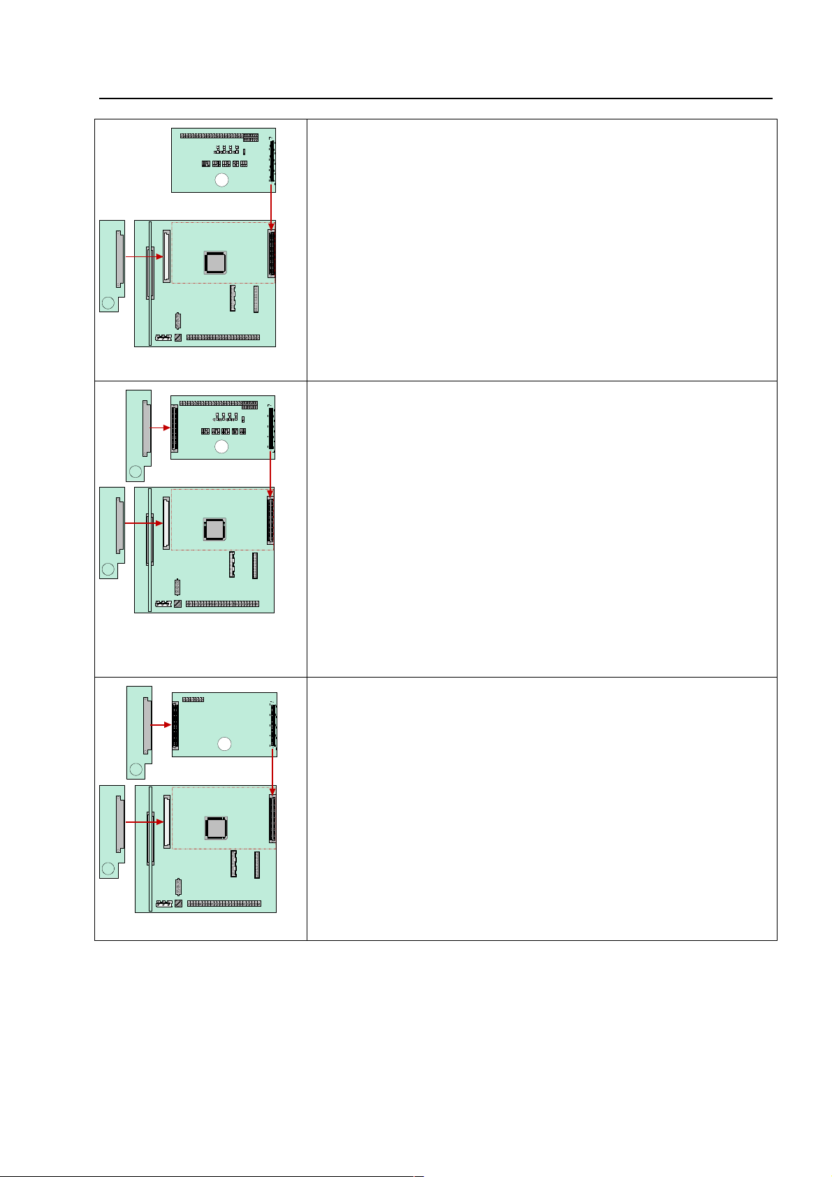
1
A
rt
c
1
2
B
1
2
C
h
s
.
e
C
Configuration options FACP 8000
FACP 8000C - Example 1:
Basic module with a micro module and a field device module (Pa
No. 772420 without micro module slot) on slot 1 of the basi
module.
With this configuration, for example, a single control panel with an
analog loop and max. 127 bus subscribers can be implemented.
FACP 8000C - Example 2:
Basic module with a micro module and a field device module (Part
No. 772418 with micro module slot) on slot 1 of the Basic m odule.
With this configuration, for example, an esser net
®
compatible
control panel with an analog loop and max. 127 bus subscribers or
a single control panel with two analog loops can be implemented.
FACP 8000C - Example 3:
Basic module with a micro module and a extension module (Part
No. 772419 ) on slot 1 of the Basic module.
This configuration is usually employed in essernet
an analog loop and max. 127 bus subscribers.
®
networks wit
Due to the lack of the field device module, no connection i
available for the fire department key pad and the master box
These devices can be connected to a different contr ol panel of th
essernet® .
Fire Alarm Computer 8000C / M
Page 57
Page 58
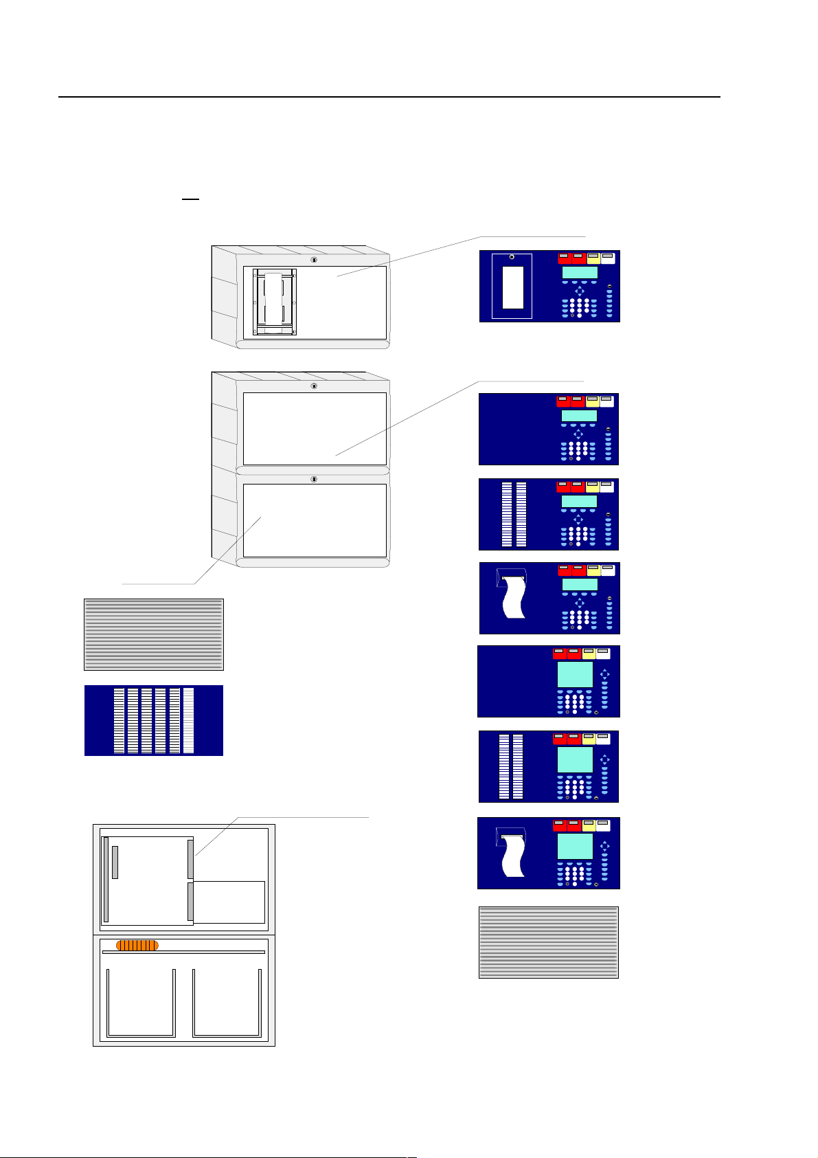
7860 _ _ or
7861 _ _ or
Front:
742100 or
7868 _ _ or
7863 _ _
7864 _ _ or
7865 _ _ or
742100
7869 _ _ or
Extension haus ing 78 9304
(not wi th ope rating m odule
7861 _ _ or 7865 _ _)
786000
772420 or
772418 or
772419 or
772421
Plug 1:
battery bag
battery bag
Basic m o dule
+
Power supply module
+
micro module slot
Extens ion mo dule
for
three
micromodule
Operating module:
Operating module:
C
onfiguration options FACP 8000M
7.3 Configuration options FACP 8000 M
The FACP 8000M can be configured in diff erent variations. The operating module front (7860_ _)
is available in various language versions. The language is def ined with the two digits of the part
number, e.g. 786002
= English lettering.
Page 58
Fire Alarm Computer 8000C / M
Page 59
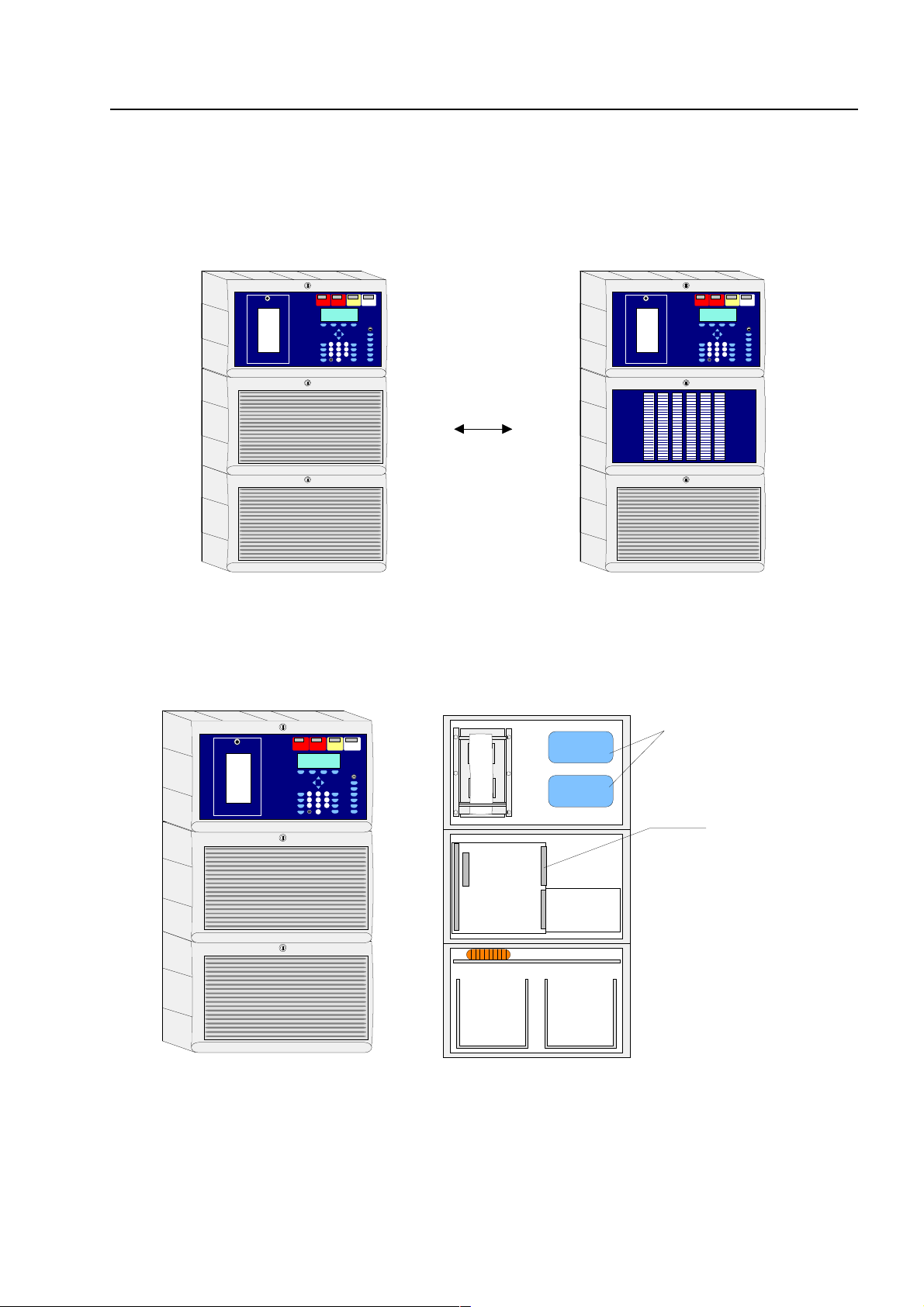
or
Extension hausing 789304
Extension hausing
789303
772420 or
772418 or
772419 or
772421
Plug 1:
Space for installation
2 x
esserbus
-transponder
esserbus
-
transponder
esserbus
-
transponder
battery bag
battery bag
Basic module
+
Power su pply m odu le
+
micro module slot
Extension m odu le
for
three
micromodule
M
Configuration options FACP 8000
Fire alarm control panel 8000M in three-piece housing with integrated printer.
The integrated printer and the operating m odule front are mounted in the upper housing. Due to
the depth of the printer, the basic module and all of the plug - in car ds ar e integrated into a separate
housing beneath. The emergency power supply with max. two 24Ah batteries can be installed into
the lowest of the three separate housings.
Ensure that the arrangement of the assemblies corresponds with the presentation shown here
during this configuration. Another distribution is not possible due to the cable length of the
operating module front, the integrated printer and the battery connection cable.
Fire Alarm Computer 8000C / M
Page 59
Page 60

Basic module
and
power supply m odule
batter y bag
batter y bag
Battery 1
Battery 2
C
onfiguration options FACP 8000M
The full conf iguration of the FACP 8000M contains a basic module, the power supply module and
two extension modules, each with 3 micro module slots. In this f ull config uration, a total number of
slots for 7 (3 + 3 + 1) fr eely selectable micr o m odule ar e available.
Fig. 5: Configuration options two and three-piece housing FACP 8000M
Additional devices
The panel configuration may be extended by additional In-/Output modules (esserbus
®
transponders). It is possible to install these transponders inside t he panel housing (depending on
available space) or remote from the panel together with available mounting boxes (IP-rating 50).
Page 60
Fire Alarm Computer 8000C / M
-
Page 61

ABCDD
Power supply
module
Basic module
A
B
C
D
M
Configuration options FACP 8000
On the basic module of the FACP 8000M, only the upper slot (slot 1) can be used for a field device
or extension module. The field device module is supported on this slot only.
The lower slot (slot 2) of the basic module is reserved for the extension module Part No.772421
(with three micro module slots). Only this extensions module can be plug ged onto the slot 2.
Configuration of the FACP 8000M
Plug 1Plug 2
Fig. 6: Configuration options (FACP 8000M)
Field device module Part No. 772420
Field device module with one micro module slot Part No. 772418
Extension module with one micro module slot Part No. 772419
Extension module with three micro module slots (FACP 8000M only) Part No. 772421
Fire Alarm Computer 8000C / M
Page 61
Page 62
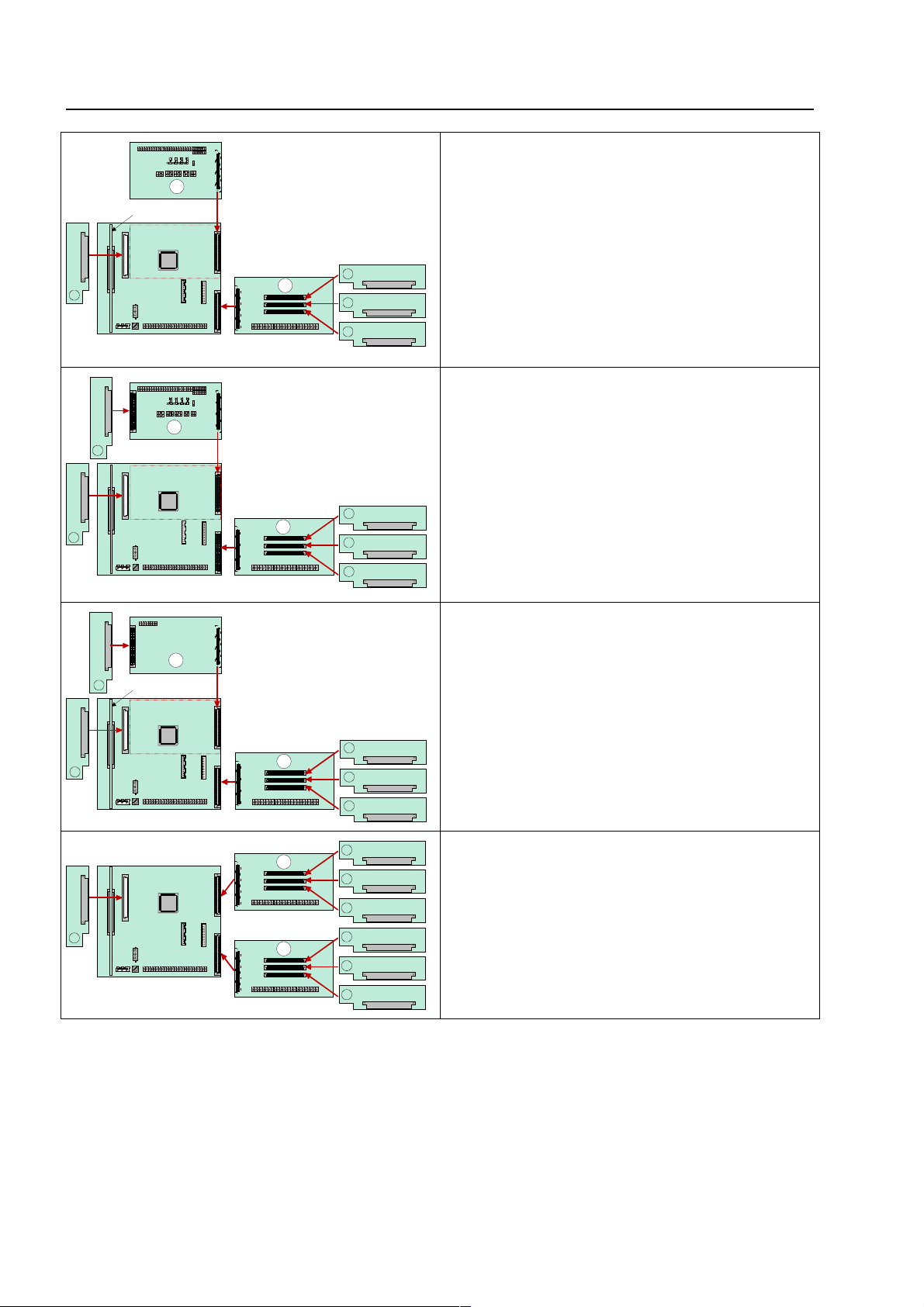
123
4
A
D
e
l
s
12345
D
B
e
e
5
12345
D
C
1234567
D
D
C
onfiguration options FACP 8000M
FACP 8000M – Example 1:
Basic module with a micro module, a field
device module (Part No. 772420 without micro
module slot) on slot 1 and one extension modul
(Part No. 772421 with 3 micro module slots) on
slot 2 of the basic module.
With this configuration, e.g. a single contro
panel with 4 analog loops and max. 508 bu
subscribers can be implemented.
FACP 8000M - Example 2:
Basic module with a micro module, a field
device module (Part No. 772418 with 1 micro
module slot) on slot 1 and one extension modul
(Part No. 772421 with 3 micro module slots) on
slot 2 of the basic module.
With this configuration, for example, a singl
control panel with 5 analog loops and max. 63
bus subscribers can be implemented.
FACP 8000M - Example 3:
Basic module with a micro module, a extension
module (Part No. 772419 with 1 micro module
slots) on slot 1 and one extension module (Part
No. 772421 with 3 micro module slots) on slot 2
of the basic module.
FACP 8000M - Example 4:
Basic module with a micro module, a extension
module (Part No. 772421 with 2 micro module
slots) on slot 1 and slot 2 of the basic module.
Page 62
Fire Alarm Computer 8000C / M
Page 63
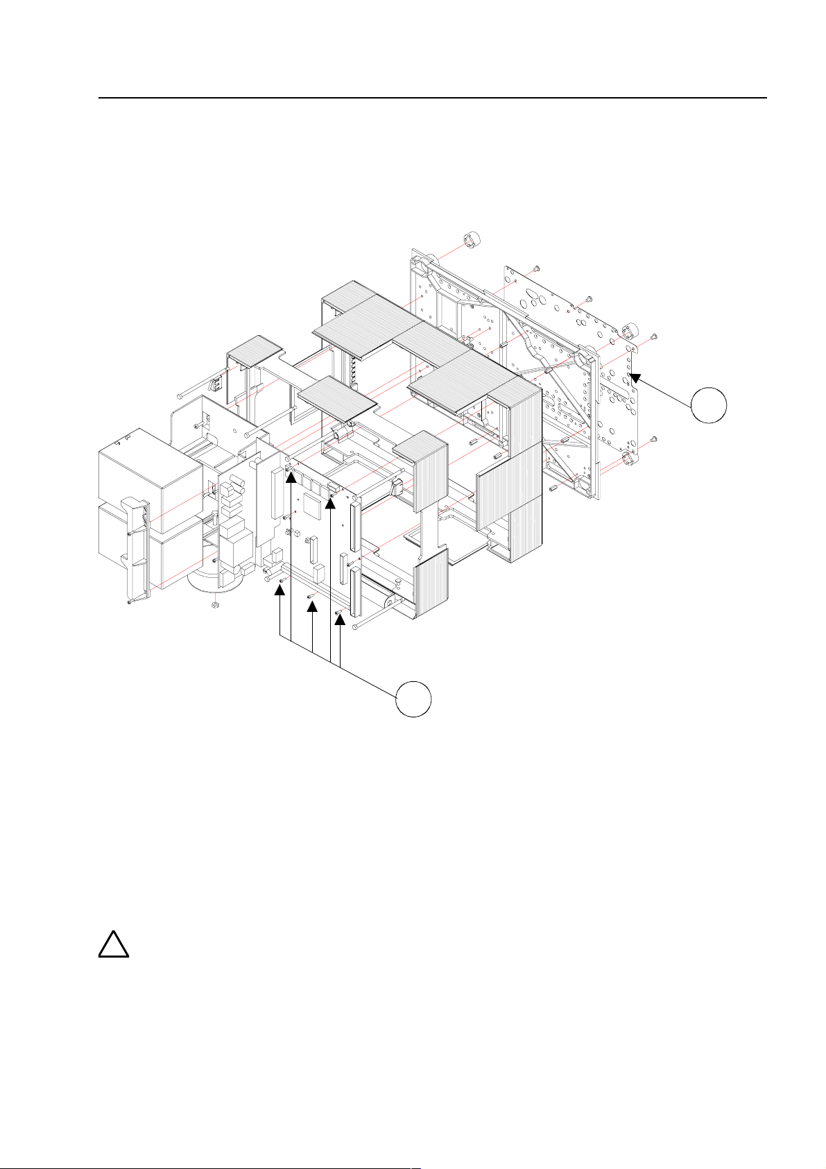
1
2
s
d
g
!
l
n
e
ly
Assemb
8 Assembly
The exploded view shows a FACP 8000C with two 12 V / 12 Ah rechargeable batteries in the
battery compartment on the lef t and the basic module installed on the right.
Fig. 7: FACP 8000C with Standard rear panel
c
d
Metal sheet of the base plate for shielding and the PE connection
Fastening screws for the basic module.
The five fastening screws are screwed into the m etal spacers. This connect ion establishe
an electrically conductive link with the metal plate of the main board. The basic and Fiel
device modules are connected via the metal plate to the PE mantle terminal for connectin
the PE supply lead.
The basic and Field device module is connected to the central housing’s rear metal pane
via the metal spacers and the met al scr ews. Without this electrically conductive connectio
between the basic module and the rear metal panel, sufficient EMC protection for th
FACP 8000C/M is not guaranteed.
Fire Alarm Computer 8000C / M
Page 63
Page 64

A
R
O
r
t
s
w
ssembly
8.1 Wallmounting
Mark the fastening points for the base plate on the assembly surface.
Each of the t wo housing variants with the standar d rear panel or the batt ery rear panel has it s own
drilling template. The dr illing template is enclosed with the additional pack for t he central unit.
ear panel fastening points
nly use flat-head screws fo
he wall compensation piece
Fig. 8: Base plate without components
all compensation piec es
Fig. 9: Standard rear panel
Page 64
Fire Alarm Computer 8000C / M
Page 65
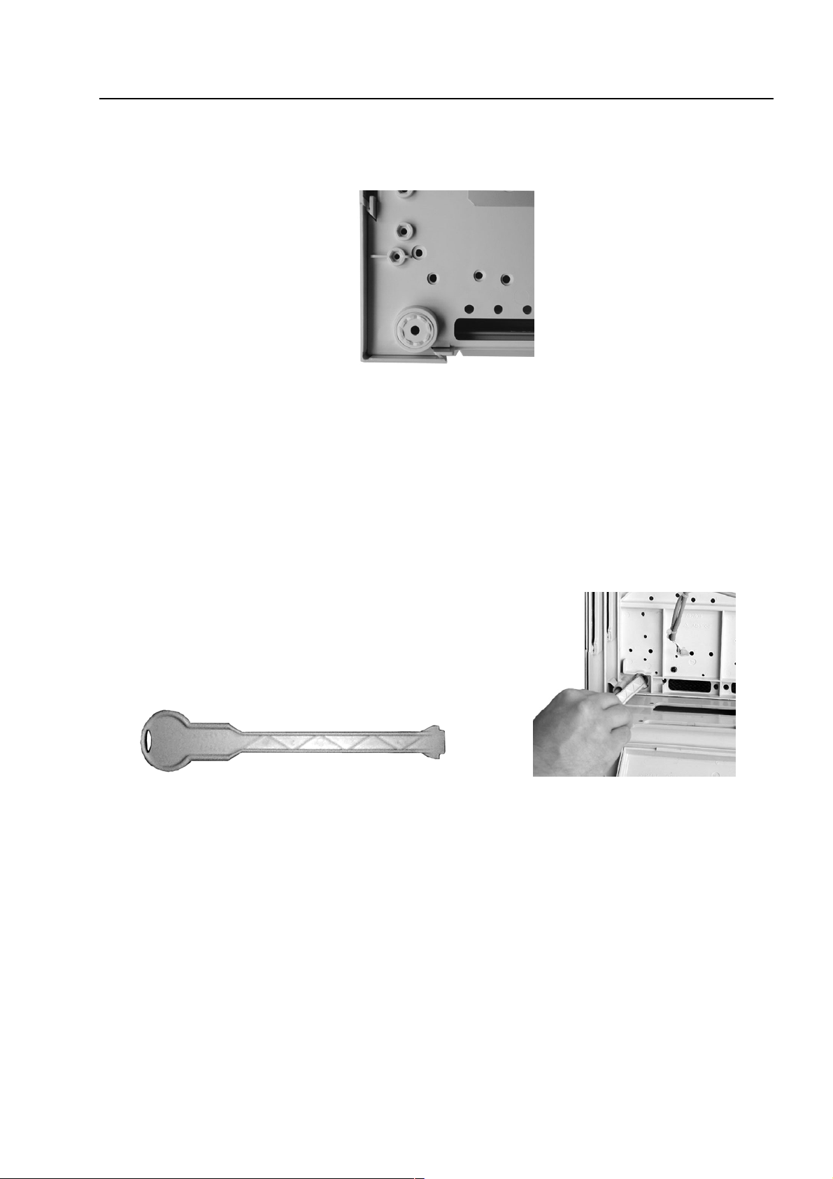
ly
Assemb
To compensate for slight wall unevenness, you can screw the four wall compensation pieces of
the base plate in or out.
Fig. 10: Wall compensation element for adjusting
The central unit’s additional pack contains a special spanner for the adjusting the wall
compensation elements.
Fig. 11: Spanner for adjusting the wall compensation elements
Fire Alarm Computer 8000C / M
Page 65
Page 66

A
A
ssembly
8.1.1
Connection between the centr al housing and the extension housing
The two connecting pieces must be used to connect the central housing and the extension
housing.
1. Remove the appropriate housing plat es from the extension housing.
2. Push a connecting piece into each of the resulting gaps. Pay attention to the assembly
direction shown on the connecting piece.
3. Push the two housings together via the guide of the connecting pieces.
connection pieces
2 x
Fig. 12: Remove the housing plates - insert the connection pieces
Assembly example with extension housing, Item No: 789300
Fig. 13: Mechanical connection to connect the two housings
(A) connecting pieces with cable glands
Page 66
Fire Alarm Computer 8000C / M
Page 67

!
l
e
n
t
n
s
ly
Assemb
8.2 Central housing
1. Remove the central housing of the FACP 8000C / M from the box.
The cover contact and both connecting cables for t he r echargeable batteries have already
been attached to the basic module.
2. Pull the ribbon cable of t he oper ating module and of the built-in printer (if present) off the
connectors of the basic module.
3. Remove the four connecting screws between the base plate and the housing frame which were
screwed in for transport.
4. The housing door (operating module and variants) has already been connected to the housing
frame at the factory. To detach the housing door from the housing frame, pull out both
retaining pins of the housing door holder .
5. The housing must be m ounted on a stable, clean and dry wall surface without mechanical
stress. The function of the snap-type connection for the housing door can be impair ed if the
housing is not correctly mounted.
Only flat-head screws and dowels with a diameter of 8 mm should be used to secure the
central unit’s housing.
Here, make sure that the scr ew head f it s into the hole of the wall compensation element and
does not project.
6. To compensate for slight wall unevenness, you can screw the four wall compensation pieces of
the base plate in or out.
The central unit’s additional pack contains a special spanner for the adjusting the wall
compensation elements.
The three unused fastening points between the base plate and the housing frame are not
necessary on the FACP 8000C / M. This fastening is intended for a different housing use.
The basic module terminals could be removed for easy installation. Disconnection of already wired
terminals is not necessary.
Danger - Electrical shock !
Disconnect all power from the panel before carrying out any installation work. The pane
may only be operated while the cabinet is closed. Operation is not allowed while th
cabinet is open, or if the housing is not fully assembled or if cabinet openings have bee
tampered with.
Risk of short circuit
All voltage and signal lines connected to the basic module must be secured to preven
slipping by using a suitable attachment mater ials such as plastic cable binders. Work o
the fire alarm central unit 8000C may only be carried out when it is deenergized (main
and emergency power supply).
Fire Alarm Computer 8000C / M
Page 67
Page 68

A
ssembly
Fig. 14: Fastening points of the four connecting screws (FACP 8000C)
Fig. 15: Fastening points of the four connecting screws (FACP 8000M)
Page 68
Fire Alarm Computer 8000C / M
Page 69

!
.
.
is
ly
ly
F
F
Assemb
8.3 Mounting the cabinet / Installation
The power and signal cabling of the FACP 8000 C/M should be led through the wall into the
cabinet. Only use the cable entries provided for this purpose.
Cable entry
ACP 8000 C
c
entry only for the 230V AC mains power cable
d
entry for the signal cables
ACP 8000 M
c
1. Lead the 230V main power cord through the wall and the cable entry provided in the rear of the
unit (see illustration). Fasten it using appropriate devices, e.g. plastic cable straps.
2. Make sure that the mains and sig nal cables don’t inter fere with the r ear panel of t he cabinet or
the cabinet frame which is mounted on the rear panel.
3. Signal cables must only be led through the other cable entries.
To prevent short circuits
All connected power and signal lines must be secured using appropriate fasteners, e.g
plastic cable binders. Make sure the m ains cable will not move and touch the signal lines
Remove all power (mains and battery) from the fire alarm system before any work
carried out.
Make sure to lead all cables complete with their outer sheaths intact into the cabinet. On
remove the insulation from those sections which are inside the cabinet.
entry only for the 230V AC mains power cable
d
entry for the signal cables
Fire Alarm Computer 8000C / M
Page 69
Page 70

A
m
t
ssembly
Compact housing FACP 8000C (with battery)
1. Insert the rechargeable battery (bat teries) into the battery compartment and secure the battery
fastener by screwing in the two screws. The mechanical battery fastener (plastic part) is
enclosed in the central unit’s additional pack.
echanical battery fastener
wo screws
Fig. 16: FACP 8000C (compact housing)
2. Carefully place the housing frame onto the base plate.
When doing so, ensur e that no connecting cables are trapped between the base plate and the
housing frame and that the insulation of the cables is not damaged.
3. Screw the four connect ing screws between the base plat e and the housing f ram e back into the
fasteners (housing corners).
Page 70
Fire Alarm Computer 8000C / M
Page 71

3
ly
Assemb
4. Insert the cover contact int o the holder on the right or left upper
must be directed downwards (see Figure). The cover contact is alr eady connected at the
factory to the basic module’s plug contact via a connecting cable.
The cover contact can be removed from the holder again for servicing and maintenance work
or, if necessary, additional cover contacts can be inserted into the remaining holders in each
corner of the housing. A total of four cover contacts can be inserted int o t he housing of the
FACP 8000C. When a single cover contact is installed, it should always be inserted into one of
the two holders in the upper part of the housing .
housing side. The contact lug
Fig. 17: Fitted housing without operating module / housing door (example 8000C)
A
5. Place the operating module with both r etaining bolts into the housing frame. When doing so,
6. This completes assembly of the central housing.
Cover contact
press the retaining bolts into th e guide sleeve as far as they will go.
Fire Alarm Computer 8000C / M
Page 71
Page 72

h
g
h
l
l
h
)
h
e
A
ssembly
8.4 Extension housing
Four different extension housing s ar e available for individual extension of the FACP 8000C/M.
Item No. Description
789300 Extension housing for batteries
Housing complete with battery rear panel, space for two rechargeable batteries wit
an individual capacity of 12 V / 24 Ah. Neutral front and fastening material for f ittin
to the central housing.
789301 Extension housing for batteries and GEA 192 MG
Housing complete with battery rear panel, space for two rechargeable batteries wit
an individual capacity of 12 V / 24 Ah. Front panel with built-in group / individua
display (GEA) for 192 detector g roups and fastening material for fitt ing to the centra
housing.
789302 Extension housing for GEA 192 MG
Housing complete with standard r ear panel for fitt ing additional subassemblies suc
as esserbus® transponders. Front panel with built-in group / individual display (GEA
for 192 detector groups and fastening materials for fitting to the central housing.
789303 Extension housing
Housing complete with standard r ear panel for fitt ing additional subassemblies suc
as esserbus® transponders. Neutral front and fastening material for fitting to th
central housing.
Fig. 18: Standard rear panel Battery rear panel
Page 72
Fire Alarm Computer 8000C / M
Page 73

ly
Assemb
The extension housing is assembled sim ilar to the central housing. The individual assembly steps
are described in the section "Assembling the centr al housing".
The following must also be observed when assembling the extension housing:
The connection pieces between the central and extension housings can be pushed into the
♦
housing only from the rear side due to the door hinge. If an extension housing is fitted at the
bottom t o an already securely installed central housing, the cent ral housing must be removed
from the assembly surface.
A separate drilling template is available f or each of the t wo housing variants with the standard
♦
or battery rear panel. The drilling template is enclosed in the central unit’s additional pack.
The fastening holes in the mount ing surface must be drilled precisely and without offset t o the
♦
side. Otherwise, use of the connecting pieces bet ween the two housings is no longer possible
in the event of major deviations.
☞
☞
Rear panel extension options
The standard rear panel may be used in combination with the extension housing (part no.
789302/03) to install addit ional com ponents. Holes E and H are provided f or m ounting the various
components. The standard rear panel allows the following extensions:
♦
♦
♦
If the extension housing with the battery rear panel is used, please not e that depending on
the rechargeable batteries used, a sig nificant weight must be supported by the fastening
screws of the extension housing. Longer 8 mm flat-head screws should always be used
here.
Each housing must be separately secured with suitable fastening m aterials such as screws
and dowels. Attachment of the extension housing with fastening only via the connection
pieces between the central and extension housing is not permissible.
®
10 esserbus
or
4 esserbus
or
5 esserbus
no. 788610/11 (holes H)
transponders, part no. 788613/14 (m ount ing holes E)
®
transponders, part no. 788610/11 (holes H)
®
transponders, part no. 788613/14 (holes E) and 2 esser bus® transponders, part
Fire Alarm Computer 8000C / M
Page 73
Page 74
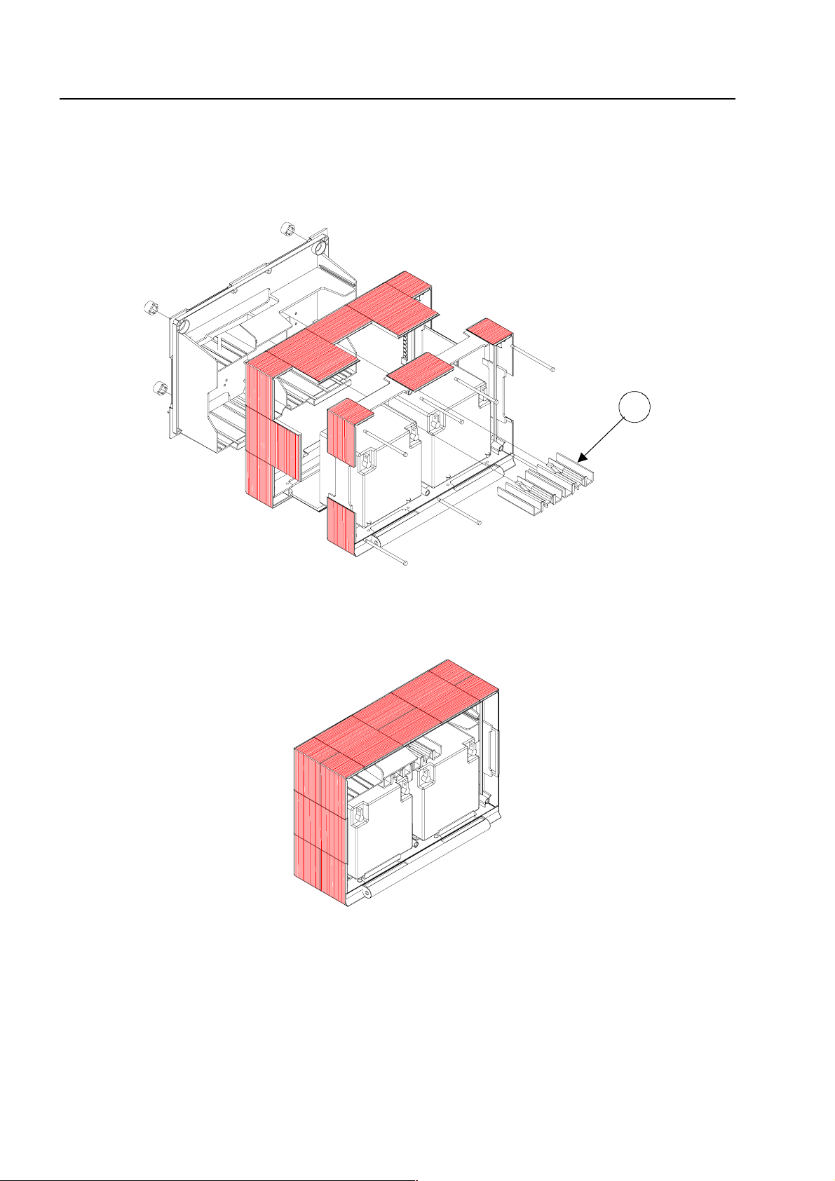
4
A
ssembly
8.5 Extension housing for two rechar geabl e batteries (789300/01)
Insert a separate fastening clamp with the corresponding lugs into t he extension housing for each
rechargeable battery. It is not permissible to install the rechargeable batteries without these
fastening clamps.
Fig. 19: Extension housing (Part No. 789300)
The required fastening clamps for the two 12 V / 24 Ah rechargeable batteries.
B
Fig. 20: Fitted extension housing without housing door
☞
Page 74
Please note that, depending on the recharg eable batteries used, the fastening screws of
the extension housing must support a significant weight. Longer 8 mm flat- head scr ews
should always be used here.
Fire Alarm Computer 8000C / M
Page 75
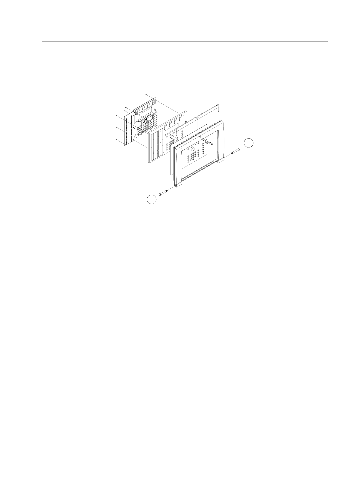
7
7
ly
Assemb
8.6 Operating module / housing door
The operating module and the housing door are supplied fully pre-assembled. Depending on the
central unit’s extension configuration, for example with or without an installed printer or group
individual display, deviation from the illustration here is possible.
Fig. 21: Exploded illustration of the operating module / housing door
The operating module is hooked into t he holder of the central unit’s housing with the two
i
retaining bolts.
☞
8.6.1
Opening
The housing door can be opened with the key vertical.
The operating module is not req uired for programming the FACP 8000C / M. The service
PC can also be directly connected to the programming connector of the basic module.
Using the ESSER service program TEDIS (optional) enables the operating module to be
completely simulated on the service PC with all functions.
Opening and closing the housing door
Closing
To close the housing door, the lock m ust be in t he horizontal position. The k ey is not required. The
housing door can simply be pushed closed and engaged in the snap-type f ast ener .
The housing door key is always required to open the housing front.
Fire Alarm Computer 8000C / M
Page 75
Page 76

1
2
B
12345
D
B
0 123
L
P
P
P
ocation of plug in cards
8.7 Definition of the Primary loop number
Individual assemblies of the FACP 8000C / M can be switched on/off with the internal primary loop
number through the control panel keyboard or programmed with the customer data editor. This
internal primary loop number is composed of the control panel number, the slot and the assembly
number.
Example: FACP 8000C / M (Panel number 01)
rimary loop number 0113
rimary loop number 0123
Fig. 22: Example FACP 8000C Example FACP 8000M
rimary loop number 0131
Subassembly number of the Basic-, Field device-
or extension module
Slot number: Basic module = No. 1
Basic module Slot 1 = No. 2
Basic module Slot 2 = No. 3 ( only 8000M)
Number of the Fire Alarm Panel ( 01 to max. 31)
Page 76
Fire Alarm Computer 8000C / M
Page 77

p
p
s
Primary loop number (Panel no. 01)
Basic module (Panel no. 01)
Primary loo
number
0111 common fault relay of the basic m odule
0112 interface of the basic module
0113 micro module slot of the basic module
Field device module in
Primary loo
number
0121 relays K2, K3 and K4 of the field device module
0122 Relay K1 of the field device module
0123 micro module slot of the Field device module
0124 internal primary loop of the Field device module
Extension module 772419 in
Primary loop
number
0121
0122
0123 m icro module slot of the extension module
0124
Extension module 772421 in
Primary loop
number
0121 m icro module slot No. 1 of the extension module
0122 m icro module slot No. 2 of the extension module
0123 m icro module slot No. 3 of the extension module
Extension module 772421 in
Primary loop
number
0131 m icro module slot No. 1 of the extension module
0132 m icro module slot No. 2 of the extension module
0133 m icro module slot No. 3 of the extension module
subassembly
slot 1
(panel no. 01)
subassembly
slot 1
subassembly
no module available
no module available
no module available
slot 1
subassembly
slot 2
subassembly
(only FACP 8000M)
(only FACP 8000M)
Location of plug in card
☞
Peripheral modules or extension modules may only be installed in
module.
Slot 2
of the basic module is unused on the 8000C FACP.
Fire Alarm Computer 8000C / M
slot 1
of the basic
Page 77
Page 78
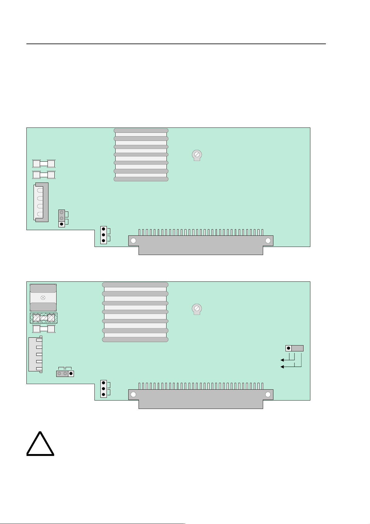
123
4
123
BR1
F1
Power supply module
F2
R15X1123ONOFF
BR2ONOFF
X5/6
F1F2R3X11
2
3
ON
OFF
BR2
3
2 1
BR1
OFF
ON
X3X21
2 3BR3
27,5V
42V
123
4
!
P
ower supply module
9 Power supply module (standard / esserbus®-Plus)
The power supply module is installed on the basic circuit board of the FACP 8000C/M. This
module accommodates the entire voltage supply f or the f ire alarm cont rol panel and the +12 V DC
supply voltage for external devices. Maximum current load from external users will depend on
control panel configuration and accounts for approx. 2A. One power supply module may be
installed in each FACP 8000C. If necessary, additional supply is possible from a monitored
external power supply unit.
Fig. 23: Power supply module standard (Part-No. 771690)
Fig. 24: Power supply module with standar d and es s er bus®-PLus functionality (Part-no. 802426)
The power supply module must only be installed or removed with the fire alarm contr ol
panel in a de-energized state.
Page 78
Fire Alarm Computer 8000C / M
Page 79
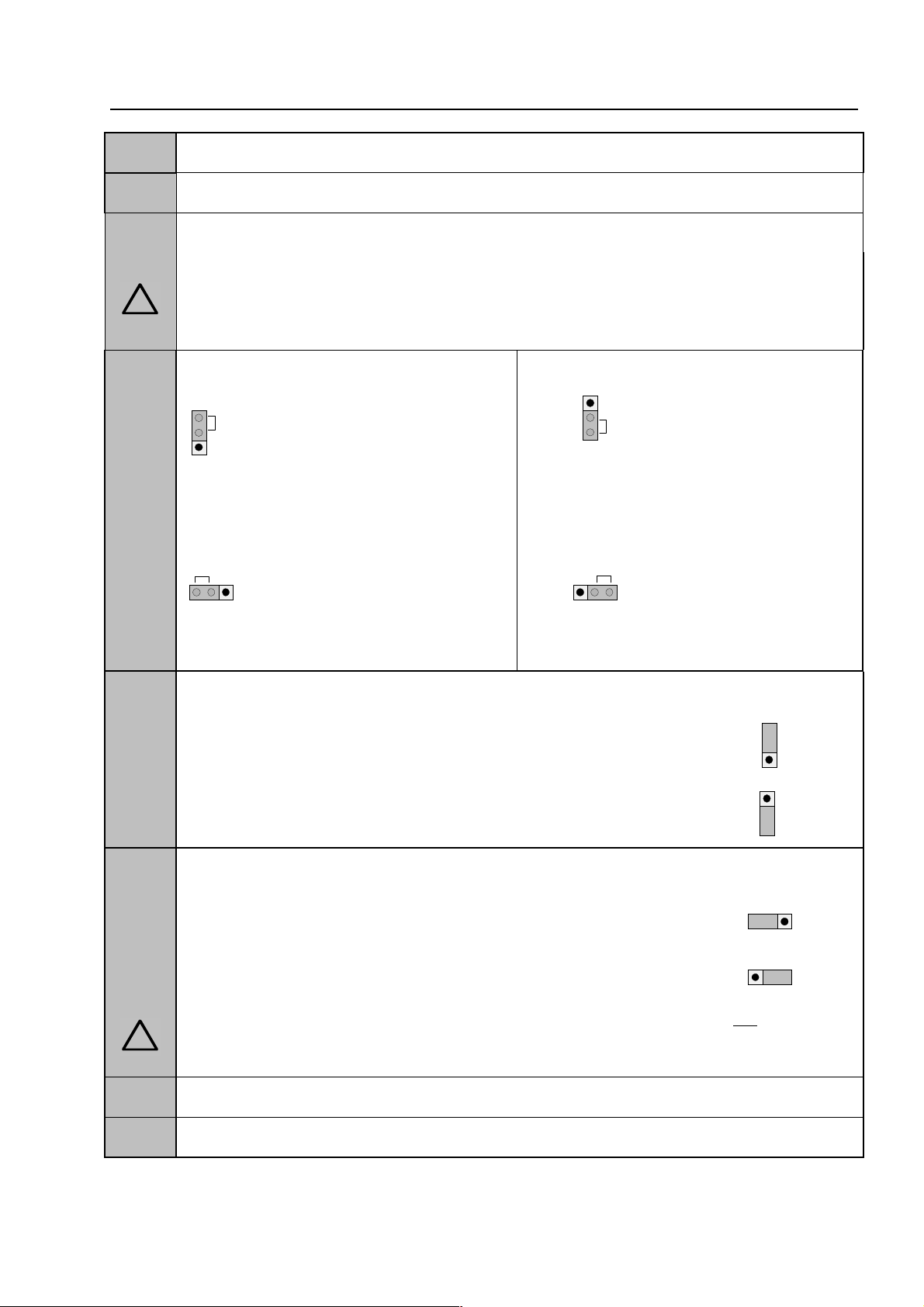
!
d
123
BR1
ON
1
2
3
BR1
OFF
3 2 1
OFF
3 2 1
ON
ON
123
OFF
1
2
3
1 2 3
1 2 3
!
A
-
le
Power supply modu
X1
F1
F2
plug connector for transformer (secondary)
fuse for the FACP inter nal supply power to the analog loop T 4 A
fuse T 8 A at 150 VA
Caution!
In order to prevent a short -circuit between the secondary voltage of the tr ansformer an
BR1
the heat sink the plastic cover must always be fitted on top of the glass fuse (F2).
standard 771690
automatic ground fault detection
(factory standard setting = ON)
esserbus®-PLus 802426
automatic ground fault detection
disabled
BR2
automatic ground fault detection disabled
(factory standard setting = OFF)
battery discharge protection (U
< 9.5 V DC)
batt
automatic ground fault detection
discharge protection enabled (factor y standar d set ting)
discharge protection disabled
BR3
jumper for selecting the internal analog loop voltage
standard systems: 27.5 V analog loop voltage
esserbus®-PLus
systems:
Mixed operation with standard and esserbus®-PLus functionality is not possible.
maximum of 4 analog loop modules, part no. 804383
PLus system with a loop voltage of 42 V.
42 V analog loop voltage, part no. 804383
required for esserbus®-PLus functionality.
may be fitted in a esserbus
®
R 3
X 2 / 3
potentiometer for adj usting the battery charging voltage to +13.8 V DC (at 20°C)
Basic module connector
Fire Alarm Computer 8000C / M
Page 79
Page 80

123ONOFF
BR2
!
e
r
e
s
P
ower supply module
Protection against deep discharging of the batteries (BR2)
In case of loss of the m ains voltage the control panel will be powered without a interruption by the
connected battery. Depending on t he capacity of the battery a backup time of up to 72 hours can
be realized. After that time t he external alarm devices must be still operable in an alar m condition.
The activation of these devices must be still possible with a minimum battery voltage of 10.5V DC.
Fig. 25: Jumper BR2 on the Power supply module
As soon as the voltage of the batter ies goes below 9.5V the battery backup will get disconnected
to protect the batteries and the cont r ol panel. The control panel is no longer operational.
Eliminate the trouble condit ion of the mains power supply and turn/switch on the control panel. The
connected batteries will get charg ed automatically if the voltag e of the batter ies during the battery
test without external load is higher than 10.5V DC. A battery failure will be indicated if the voltage
of the batteries does not exceed this level. Discharged batteries have to be recharged with an
external power supply or need to be replaced. The protection for deep discharging of the batteries
can be enabled / disabled with the jumper BR2. (BR2 closed = battery protection enabled / BR2
open = battery protection disabled)
Exhausted batteries (off- load voltage U
battery types approved by the fire alarm control panel manufacturer may be used fo
supplying the fire alarm control panels with backup power. Please pay attention to th
manual of the manufactur er of the batteries. It is possible that deep discharged batter ie
can not be used and need to be replaced.
< 10,0V DC) will not charge correctly. Only th
battery
Page 80
Fire Alarm Computer 8000C / M
Page 81

le
Power supply modu
Battery monitoring (Basic module)
The power supply unit periodically monitors the charge of t he batteries connected. If this battery
test reveals a battery voltage of below 10.0 V DC under load, battery trouble will be signalled. The
battery charge is controlled by means of a tem per ature-dependent resistor (NTC).
If only one battery is connected,
order to deactivate monitoring of battery connection 2. Alternatively, the second, unused battery
connection cable may also be connected to the first battery in order to override the battery
monitoring facility f or t he absent second battery.
If a batter y is connected without deactivating or overriding the monitoring of the second bat tery,
battery trouble will be signaled the next time an internal control panel battery test is performed.
solder jumper BR1 on the basic circuit board
may be closed in
Fire Alarm Computer 8000C / M
Page 81
Page 82

Printer
GND
+UB
ext.
NPEL1/U
mains 230V ~
X19
X18
X11
X12
X13
X14
micro module
RxD
TxD
TTY
GÖS
SaSI1I2
1 2 3 4 5 6 7 8
F1
T630mA
X110
Battery
3V/270mAh
Basic module
S1
Reset
+
-
Battery 1
Battery 2PEBR4
D5
D6
D7
V41
V42
X7
X10
V31
V33
send
LED
Polatiry
reversal
indication
* Plug 2
X15D4V43
BR5
BR6
BR7
A B
A B
A B
RS
485
S5
5 6 7 8
D29
BR1F2T2A
battery jumper
F3
battery 1
T2,5A
F4
battery 2
T2,5A
X8
+-+
-
1 2 3
1 2
1 2 3
1 2 3
BR2
Printer
1
DK
!
.
l
k
B
asic module
10 Basic module of the FACP 8000C / M
X17
X16
X22
X23
1 2 3 4
Slot for micro module
Plug 1
Slot for power supply module
X21
X20
Printer connection
terminals
transformator
Operating modulel
Fig. 26: Basic module
* Terminal 2 (Plug 2) is equipped only by FACP 8000M (next Page see Table).
Replacing the operating system software
When replacing the operating system software (EPROM D6 + D7), the customer data is
automatically deleted. Bef or e changing the EPROM, save your data on the hard disk of the service
PC. After installing the new operating system soft ware, the customer data can be transferred back
from the service PC to the FACP 8000C / M.
To prevent short circuits
All connected power and signal lines must be secured using appropriate fasteners, e.g
plastic cable binders. Make sure the mains cable will not move and touch the signa
lines. Remove all power (mains and battery) from the f ir e alar m system before any wor
is carried out.
Page 82
Fire Alarm Computer 8000C / M
Page 83

!
e
d
e
l
g
it
r
l
e
e
n
le
Basic modu
Battery
G21 / G22
Battery monitorin
BR1
BR2
BR3-BR7
D6 / D7
X22, 23 / LED V43
S5 / LED V42
LED V41
F1 Mains fuse
F2
F3
F4
Reset-button S1
Slot 1
Slot 2
X7
X8
X10
X11, 12, 13, 14
X15
X16,17
X18
X19
X20, 21
X26
The functions of the various jumpers and the connector pin-outs are described in the following
sections of this manual.
3V DC / 270 mAh
Warning : Danger of explosion in case of inappropriate replacement of th
3V/270 mAh battery! Only use an identical batter y or a type recommende
by the manufacturer. Used batteries should be disposed of observing th
recommendations of their manufacturer. Only replace with an identica
battery or a type recommended by the manufacturer .
Connection for two batteries ( 2 x 24 ampere hours max.)
If only one battery is connected, solder jumper BR1 on the basic circu
board may be closed in order to deactivate monitoring of battery connection
Solder jumper for enabeling an internal printer
Jumper set at the factory. Do not alter.
EPROM containing the operating system software version 2.38 or highe
and the customer data memory. Use an appropriate PLCC extraction too
when replacing the EPROM.
Cover contact connection (FACP housing). LED V43 light s while the cover
is open.
DIL switch – do not alter the fact ory setting (" OFF") . I n position "O FF" of t h
DIL switch, LED V42 will not be activated.
lights during emergency operat ion of the 8000C/M FACP.
Limited functionality of th e FACP.
For Basic module part no. 772417 and 772424 = T630mA
For Basic module part no. 772427 and 772428 = T1A
Fuse T2A - +12 V DC external supply voltage
Fuse T2.5A – battery charge current, battery 1
Fuse T2.5A – battery charge current, battery 2
RESET button for initiating a control panel reset
(cold start, is only possible with the cover contact open)
Plug contacts to the Field device- or Extension module 772419
FACP 8000C
FACP 8000M plug contacts to the Extension module 772421
Connector for display and control panel.
Connection via a 40 pole ribbon cable, length approx. 50 cm
Connector for the micro module slot, the internal serial interface, th
common trouble relay, inputs I1 and I2, the control voltage for the built-i
printer and the supply voltage (12 V DC, Ub
Connector for built-in print er (ribbon cable, 34 pole)
Jumper for disabling the EMC protection for the essernet® interface
Connector for the service PC (FACP inter face required)
Micro module slot for a freely selectable micro module
Transformer connector ( pr im ar y, 230 V)
Mains terminals, L1/U, N, PE ; 230 V AC/ 50 to 60 Hz, ma x. 1. 5- 2.5 mm2
Slot for power supply module
Additional terminal for prot ective earth (PE)
equipped!
not
) for external equipment .
ext
Fire Alarm Computer 8000C / M
Page 83
Page 84

removable
B
asic module
The microprocessor f or controlling the control panel f unctions, the operating system EPROM and
the customer data EPROM for the saving of data recorded in the cust omer data progr amming are
to be found on the basic module. The power supply module for the voltage supply of t he control
panel and the connected exter nal devices is plugged onto the basic module. Additionally, a freely
selectable micro module can be plugged onto the basic module. A field device or
module is plugged into slot 1. Slot 2 is only used on the FACP 8000M. The extensions module
772421 (with 3 micro module slots) can be plugged into slot 2.
an extension
☞
Connection terminals
To simplify installation, you may detach the connection terminals from the basic card. After
connecting the wires, fit the terminal strip back onto the plug-in contacts on the basic card.
Fig. 27: Connection terminals
The field device module (when present) must always be plugged into
module.
Slot 2
is without function on the basic module FACP 8000C.
slot 1
of the basic
Page 84
Fire Alarm Computer 8000C / M
Page 85

X19
L1NPE
FE
mains 230V~
housing mantle
terminal
cable cross section at l east
2,5 - 4
mm² to potential
compensation rail
NPEL1/U
!
.
.
le
Basic modu
10.1 Mains connection
Connection of the 230 V AC mains supply lead for voltag e supply to t he fire alarm control panel.
Fig. 28: Mains connection and PE conductors
The 230 V AC mains supply must be installed in accordance with local regulations by a
♦
qualified technician.
The fire alarm system must be supplied f rom the 230 V mains through a separate isolator or
♦
an appropriately labelled safe ty switch. In buildings fitted with earth fault devices, a separate
device must be installed for the fire alar m system.
The fuse for the power supply of t he fire alarm system must be clearly labelled with the red
♦
marking ‘FACP’.
The protective earth conductor of the mains cable must be connected to the corresponding
♦
screw terminal at the fire alarm panel.
The FE (functional earth) and PE (protective earth) terminals of the panel’s cabinet must be
♦
connected with the PE rail of the power distribut or panel from which the fire alar m system will
be powered.
Use an appropriate mains cable, e.g. NYM 3 x 1.5 mm
♦
specifications.
The installation must comply with local regulations on electrical safety.
♦
To prevent short circuits
All connected power and signal lines must be secured using appropriate fasteners, e.g
plastic cable binders. Make sure the m ains cable will not move and touch the signal lines
Remove all power (mains and battery) before any work is carried out.
Make sure to lead all cables complete with their outer sheaths intact into the cabinet. Only
remove the insulation from those sections which are inside the cabinet.
2
or a cable type with similar
Fire Alarm Computer 8000C / M
Page 85
Page 86

Basic module
+
Power supply module
+
micromodule slot
battery bag
metal screws to the
rear wall plate of t h e
central unit's housi ng
housing
mantle terminal
L1NPE
FE
Cable cross section at least 2,5 - 4
mm²
to pote n t ial comp ensation rail
NPEL1/U
!
s
l
B
asic module
10.1.1 Protective Earth - FACP 8000 C
The FE (functional earth) terminal of the FACP cabinet must be connected to the PE rail. Use
copper cable with a cross section of at least 2.5 mm
cable run. The FACP 8000 C is a protection class I device.
2
to 4 mm2 depending on the length of the
Fig. 29: Connection PE conductors between mantle terminal
The base module is connected to the r ear panel of t he cabinet by means of metal spacer
and screws. This electrically conducting connection between base module and rear pane
is essential for correct functional earthing of the FACP 8000 C/M.
Page 86
Fire Alarm Computer 8000C / M
Page 87

Basic module
+
Power supply module
+
micromodule slot
battery bag
battery bag
metal scr e ws to the
rear wall plate of the
central unit's housing
Cable cross section at least
2,5 - 4
mm² to potential compensation rail
housing
mantle
terminal
L1NPE
FE
NPEL1/U
!
s
l
le
Basic modu
10.1.2 Protective Earth - FACP 8000 M
The FE (functional earth) terminal of the FACP cabinet must be connected to the PE rail. Use
copper cable with a cross section of at least 2.5 mm
cable run. The FACP 8000 M is a protection class I device.
2
to 4 mm2 depending on the length of the
Fig. 30: Connection PE conductors between mantle terminal
The base module is connected to the r ear panel of t he cabinet by means of metal spacer
and screws. This electrically conducting connection between base module and rear pane
is essential for correct functional earthing of the FACP 8000 C/M.
Fire Alarm Computer 8000C / M
Page 87
Page 88

X11 X12
X13
X14
X11 X12
X13
X14
B
asic module
10.2 Connecting the micro module
Eight connection terminals are provided at slot X17/ 18 on the basic card for connecting the fr eely
selectable micro module.
Assignment of t he eight screw terminals will depend on the micro module type used. Terminal card
assignment is described for each micro module in Section
Micro module
.
All jumpers in vertical position
All jumpers in horizontal position
☞
If a essernet® micro module is used in the micro module slot, the int eg rated EMC f ilter m ust
be disabled. EMC protection of the essernet
external devices.
EMC protection for this micro module connection
⇒
terminal is activated (factory default)
®
essernet
⇒
Only required for essernet
protection for this micro module terminal is
disabled.
micro module
®
micro module. EMC
®
cabling has to be ensured by appropriate
Page 88
Fire Alarm Computer 8000C / M
Page 89

ABA
RxD
TxDBexternal device
Rx -
Rx +
Tx -
Tx +
TTY
n
Y
d
e
f
e
A
B
RS485
le
10.3 Serial interface
send
receive
receive
send
Basic modu
These four terminals may be used for connecting a
external device, e.g. a protocol printer, via the TT
interface (20 mA).
The cable length between external device an
interface must not exceed 1000m.
If wired correctly, the gr een LED V56 will blink at th
transmission frequency to provide visual indication o
proper interface wiring.
If the connection cables are transposed at th
terminals, red LED V 44 will light up.
The connection terminals A/B of the RS485 interface on the basic module are r eserved for future
function extensions and are not supported on this version of the central unit.
RS485 interface
not for FACP 8000 C / M
Fire Alarm Computer 8000C / M
Page 89
Page 90
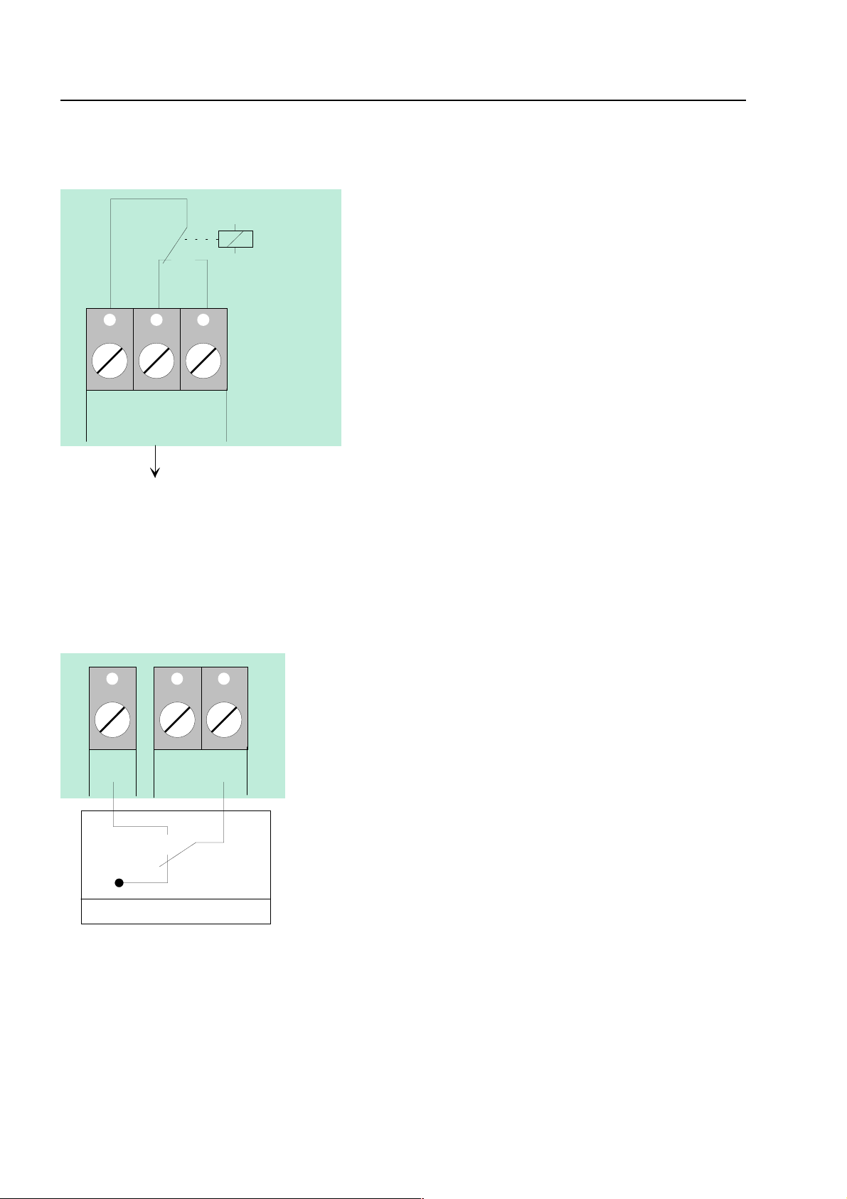
GÖS
SaS-Relay
external devices
SaS
t
d
e
e
e
e
e
f
GND
e. g. external power supply
1I2
o
r
e
5
e
t
t
is
o
l
B
asic module
10.4 Common trouble relay
The relay is a potential-free change-over contac
assigned permanently as a common trouble relay an
is activated when the fire alarm contr ol panel is in th
normal mode.
If the control panel detects at least one troubl
incident, relay activation will be interrupted and th
relay will change its control status.
This application also permits transmission of a troubl
signal via the potential-free relay contact when th
control panel is in CPU failur e mode or in the event o
mains and battery failure.
10.5 Inputs IN1 and IN2
I
Monitored inputs IN1 and IN2 allow you to monitor tw
external devices, such as an external power supply fo
feeding the control panel components.
For each input, Custom er Data Editor 8000C may b
used for entering specific additional text of 2
characters in length that will be shown on th
alphanumeric display and protocol printer in the even
of an incident.
An external contact is required for activating an inpu
and will be open in the normal mode. This contact
used to switch input IN1 or IN2 to GND in order t
send a trouble message to the fire alarm contro
panel.
Page 90
Fire Alarm Computer 8000C / M
Page 91

5 6 7 8
4
1
8
set
jumper
1
8
set
jumper
1
8
le
Basic modu
10.6 Connection of the cover contacts
Depending on the central unit housing used, up to f our cover contacts can be connected to the
connection terminals X22/23 of the basic m odule. However, only one housing contact is present
on the FACP 8000 C / M. The opened housing contact is indicated by the illuminated LED V43.
5 6 7
4 3 2
3 2 1
Fig. 31: Connection of one cover contact Fig. 32: Connection of two cover contacts
5 6 7
5 6 7
4 3 2
4 3 2
Fig. 33: Connection of three cover contacts Fig. 34: Connection of four cover contacts
☞
The cover contact must be opened when the service PC is connected, otherwise
connection of the PC is not recognized by the central unit .
Fire Alarm Computer 8000C / M
Page 91
Page 92

S5
OFF
B
asic module
10.7 DIL switch S5
On the FACP 8000C / M, this DIL switch has no function.
For fault-f ree operation, the DIL switch S5 must always be set to "OFF" . The LED V42 must not
light up.
Switch position "OFF" requir ed for FACP 8000C/M
10.8 Reset-Function
Pressing the RESET button S1 initiat es a r estart of the cent ral unit. Alar m and f ault messag es are
reset, and all alarm groups and prim ar y lines are act ivated.
A cold start of t he central unit with the RESET pushbutton is only possible with the cover contact
open (central unit housing).
Page 92
Fire Alarm Computer 8000C / M
Page 93

+
switched
+12 V ext.
permanently
positive
+UBext
F2
T2A
X10
le
Basic modu
10.9 Connecting the built-in printer
The built-in printer of t he FACP 8000C is connected to terminal X 10 of the basic module via a
ribbon cable.
The power supply for the built-in printer is connected to the connection terminal Ub
DC/GND). A switched +12 V DC voltage is available for connecting the built-in printer.
(+12V
ext
Printer
Fig. 35: Connection terminals of the built-in printer
☞
Only the built-in printers approved by the manufacturer may be connected to these
terminals.
Plug 2
Fire Alarm Computer 8000C / M
Page 93
Page 94

!
e
F
ield device module
11 Field device module
There are two different kinds of field device module available for the FACP 8000C / M.
1) Field device module with one micro module slot (Part no. 772418)
2) Field device module (Part no. 772420)
The field device module integrates all of the input and output modules that are necessary in
addition to the modules on the basic module for t he FACP 8000C to operate as a fire alarm control
panel to DIN VDE 0833.
An fire alarm control panel 8000C / M will accommodate a f ield device card for connecting a fire
department operating panel and a master box. Three freely programmable relays are also
provided for any output function that m ay be required. Coding bridges (BR9- BR20) may be used
for setting the activation mode for these three relays (K2, K3, K4) to monitored and positiveswitching, positive-switching or as a potential- free chang e-over contact. T he coding bridges (BR3BR5) may also be used for setting these relays to activate if an event occurs while the control
panel is in the CPU failure mode.
If a control panel is required to function in accordance with DIN 0833, you should program the
relays with the
data of the control panel.
common fire (K2), common alarm (K3)
common disconnection (K4)
and
in the customer
☞
On leaving the fact ory, only relay K1 is config ured to activate the m aster box in CPU f ailure
mode.
Do not connect relays (AE) of the FACP 8000C/M with alternating voltage. Even in the cas
potential free relay
of a
mode it is not possible to switch an external AC-voltage
Page 94
Fire Alarm Computer 8000C / M
Page 95
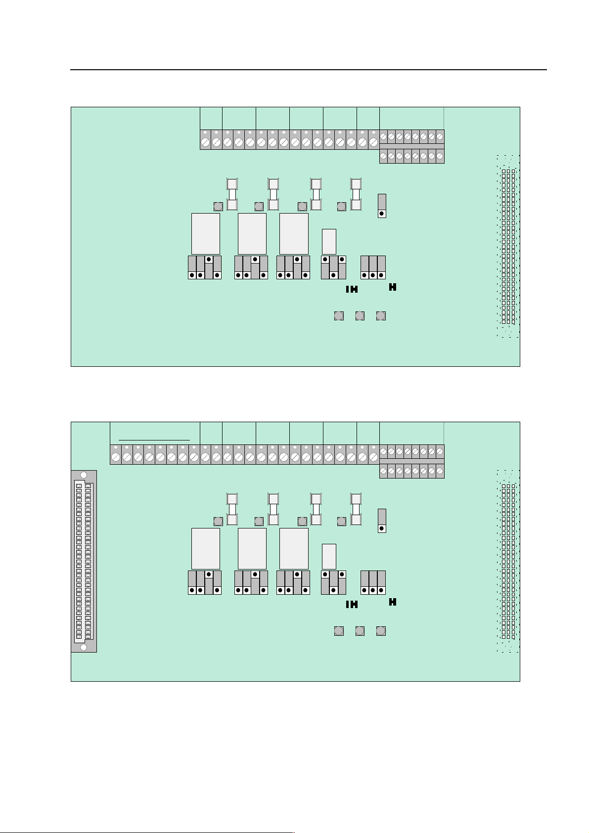
le
123
X4X5X6X7X8X9X10
F1F2F3
F4
MM21GÖS
GR1
+-K4
2A5
BR1
BR2
V20
V21
V22V8V10
V11
V12
K1
GÖSK3GÖSK2GÖS
K1
8
2A5
2A5
2A5
K3K4K2
123123123123123
Field device module
1
2
3
X4X5X6X7X8
X9
F1F2F3
F4
GÖS
GR1
+-K4
2A5
BR1
BR2
V20
V21
V22V8V10
V11
V12
K1
GÖSK3GÖSK2GÖS
K1
2A5
2A5
2A5
K3K4K2
1
231
231
231
2
312
3
Field device module
Field device modu
RÜCK.
GND
BR21
BR19
BR18
BR17
BR15
BR14
BR13
BR11
BR10
BR 9
BR 8
BR 7
BR 6
BR 5
BR 4
BR20
BR16
BR12
BR 3
Fig. 36: Field device module 7724120 (without micro module slot)
BR19
BR18
BR17
BR15
BR14
BR13
BR11
BR10
BR 9
BR20
BR16
BR12
BR 8
RÜCK.
GND
BR21
BR 7
BR 6
BR 5
BR 4
BR 3
Fig. 37: Field device module 772418 (with micro module slot)
☞
The field device module (when present) is f itted to slot Plug 1 on the basic module of the
FACP 8000C / M.
Fire Alarm Computer 8000C / M
Page 95
Page 96

l
F
ield device module
Relay K1
Relay K2,3,4
X4
X5
X6
X7
Relay for connecting a master box. May also be used as a freely programmable
relay.
Selection of operating mode and emer gency function by means of jumpers.
(Monitoring range 50 Ω to 1 kΩ)
Contact rating when used as a
non-monitored change-over contact
< 30 V DC/
max.1 A
Relay with common function. May also be used as a freely programmable relay.
Selection of operating mode and emer gency function by means of jumpers.
Contact rating when used as a
non-monitored change-over contact
< 30 V DC/
max.1 A
8 inputs for connecting a f ire depar tment operating panel
8 outputs for connecting a fire department operating panel
Connection terminals for (mast er box relay, K1)
for connecting the master box supply voltage, inc. confirmation input for verifying
master box activation
Connection terminal for relay K2
Connection terminal for relay K3
X8
X9 / GR1
F1 to F4
V8, V10,
V11, V12
V20 to V22
BR1 and BR2
BR3 to BR5
BR6 to BR20
BR21
Connection terminal for relay K4
Internal primary line input (XX24, XX= FACP number)
normal operation
fire alarm
R = 10 kΩ
→
R ≤ 5 kΩ
→
Fuses for the four relays (T 1A)
The LED lights while the corresponding relay is activated or when is has been
programmed for inverse cont r ol in the customer data programming.
yellow LED V 20 will light up when the fire alarm control panel is operating in
CPU failure mode
green LED V 21 will light up when the cover contact (control panel housing)
is open
red LED V 22 will light up if a fire alarm is det ected while the control pane
is operating in CPU failure mode
Solder bridges for setting the master box control in emergency operation
Jumpers for setting the CPU failure mode function f or relays K2, K3, K4
Jumpers for setting the operating mode of the master box relay and the three
freely programmable r elays K2, K3, K4
Coding jumpers for the FDOP connector with
fire event control out.
(Terminals X4/IN8)
Jumper in position 1-2 →
Jumper in position 2-3 →
fire event control out
fire event control out
not connected
connected (factory setting)
Page 96
Fire Alarm Computer 8000C / M
Page 97

removable
removable
X4
IN
OUT
GR1
10K
R*
le
Field device module / extension modu
Connection terminals
To simplify installation, you may detach the connection terminals from the field device module.
This is done by carefully lifting the scr ew terminal from t he field device module using a suitable
tool (e.g. screwdriver). After connecting the wires, fit the terminal strip back onto the plug-in
contacts on the field device card.
Fig. 38: Connection terminals Fig. 39: Fire department operating panel
11.1 Connection of the micro module
Eight connecting terminals are provided f or the micro module slot of the Field device module. The
actual connection of the eight terminals depends on the type of module used. The various
configurations for the different micro modules are descr ibed in the
☞
If an essernet® micro module is used, this module may only be inserted into the micro
module slot of the basis module. The essernet
®
micro module requires adaptation of the
micro modules
section.
terminal card on the basis module by means of jumper s X11-14.
11.2 Primary loop input Pri+/Pri-
Monitored primary loop input Pr i+/Pri- ( terminal X 11) has the purpose of monitoring CPU f ailure in
the essernet
another fire alarm control panel. In the event of trouble in the esser net
signal may still be sent via the relay contact to the prim ary loop input of this contr ol panel. The
alphanumeric display at this fire alarm contr ol panel will then show the message " Prim. loop fire" in
the event of an incident occurring.
The primary line input can be switched off or on and reset via the corresponding primary line
number. The primary line number of this input is determined as follows:
Primary loop No.: XX24 (XX = panel no. 01-31)
®
system. These terminals are used, f or example, to connect the comm on fire relay of
= monitored end-of-line resistor R =10 kΩ
R*
®
micro module, a fire alarm
R= 10 k
R= 5k
R= 1k
Ω ⇒
Ω ⇒
normal status
Ω ⇒
Fire alarm, display
trouble
"Prim. loop fire"
Fire Alarm Computer 8000C / M
Page 97
Page 98

I
I
I
I
I
I
I
I
X4
X4
ff
top
t
!
t
F
ield device module
11.3 Connecting a fire department operating panel
A fire department operating panel may be connected to terminals X4-X 7. Wir ing differs fr om area
to area and is governed by the requirements of the regional fire department.
acoustic signals o
MB activation
fire control off
do not use
FD call LED on (IN1 on GND)
(closer)
MB disconnected
acoustic signals off
CHECK MB
(revision)
N8
reset FACP
N7
N6
N5
N4
do not use
N3
do not use
N2
N1
bottom
top
OUT8
OUT7
terminals
terminals
fire control off
bottom
terminals
erminals
prevent
(revision)
OUT5
OUT6
MB disconnected
OUT4
common fire
OUT3
MB activated
extingguishing
system activated
OUT1
OUT2
Fig. 40: Connection terminal for the fire department operating panel
Outputs (OUT1 to OUT 8) at the fire department operating panel interface may have a
maximum load current intensity of no more than 25 mA per output
If the inspection input (terminal IN8) is not used, jumper BR21 must always be fitted a
position 1-2 !
Page 98
Fire Alarm Computer 8000C / M
.
Page 99

BR1
BR2
K1
GÖS
K1
K3K4K2
123
BR 1
e
BR 1
BR 2
r
BR 2
)
r
le
11.4 Connecting the master box (Relay K1)
Relay K1 for the connection of a master box is part of the peripheral module.
The control configuration of relay K1 can be set to
switching the positive potential
or as a
non-monitored change-over contact
(BR6 – BR8). The setting depends on the act ual r equirements.
RÜCK.
GND
monitored and switching the positive potential,
by means of jumpers
Field device modu
BR 8
BR 7
BR 6
Fig. 41: Location of the master box relay K1 and the jumpers BR 6-8 on the field device module
Setting the operating mode for relay K1
Activation of master box relay (K1) also in the event of a fire alarm with th
control panel in the CPU failure mode ( state on leaving factory)
No activation of the master box in the event of CPU failure-fire
No activation of the master box in the event of a f ire alarm when the cove
contact on the control panel housing is open. (Sta t e on leaving factory)
Activation of master box even with cover contact open (outer housing)
R*
S*
Monitored end-of-line resistor R = 680 Ω (state on leaving factory
Monitoring capability of internal resistor in mast er box 50-1000 ohms (refe
to customer data programm ing )
Potential-free confirmation contact in master box
Fire Alarm Computer 8000C / M
Page 99
Page 100

680
R *
S*
GÖS
K1
K1
BR8
BR7
BR6
123123123
Master box
(schematic circuit diagram)
Fire alarm c ontrol panel 8000 C
Field device module
680
S*
R*
FSK adapter
SDA-97
784708
1098
7
+UB
+
-
ÜE -
ÜE +
+ UB ext.
alarm
+UBSG
acknowledge
MFAB acknowledge
F
ield device module
Operating mode: positive switching ( + 12 V DC
RÜCK.
GND
panel int.
+monitoring
+12V DC Ub int.
Fig. 42: Terminal of the master box relay K1
/ max. 1A) and monitored
intern
Ω
Fig. 43: Schematic circuit diagram master box with FSK adapter (main key depot)
Page 100
Fire Alarm Computer 8000C / M
 Loading...