

Page 1
D
Achtung!
Diese Anleitung ist vor der Inbetriebnahme genau
durchzulesen. Diese Installationsanleitung ist eine
ergänzende Information zur der technischen
Dokumentation des Herstellers. Bei Schäden die durch
Nichtbeachtung dieser Anleitung verursacht werden,
erlischt der Garantieanspruch. Für Folgeschäden, die
daraus resultieren wird keine Haftung übernommen.
Important!
Read these instructions carefully before starting assembly.
This manual is an additional information to the supplied
installation manual of the manufacturer. Any damage
caused by failure to observe the installation instructions
voids the product guarantee. Furthermore, no liability can
be accepted for any consequential damage arising from
such failure.
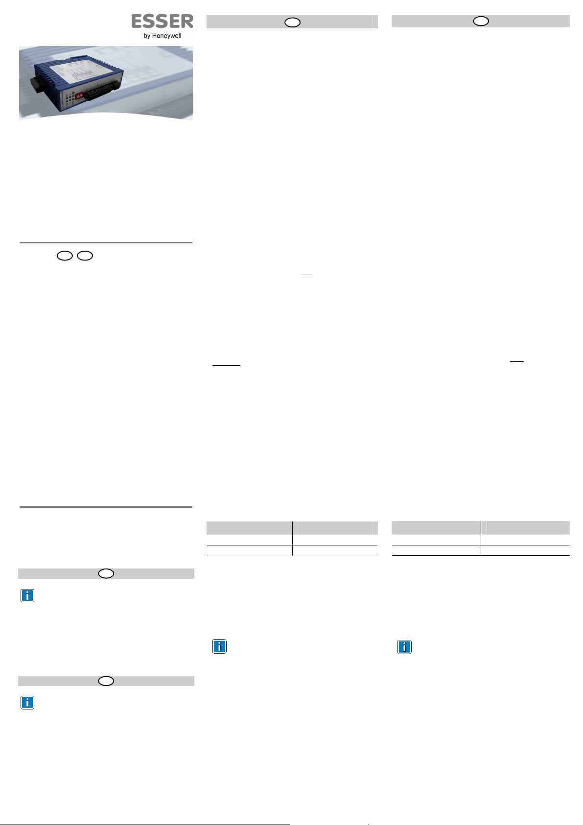
GB
Installationsanleitung
LWL-Konverter für essernet
Installation Instruction
FOC converter for essernet
®
®
(Art.-Nr. / Part No. 784765)
798963.10
07.2009
D
GB
Novar GmbH a Honeywell Company
Dieselstraße 2, D-41469 Neuss
Internet: www.esser-systems.de
E-Mail: info@esser-systems.de
Ergänzende und aktuelle Informationen
Die Produktangaben entsprechen dem Stand der
Drucklegung und können durch Produktänderungen,
geänderte Normen / Richtlinien ggf. von den hier
genannten Informationen abweichen.
Aktualisierte Dokumentationen, Informationen und
Konformitätserklärungen stehen zum Abgleich auf
der Internetseite www.esser-systems.de zur
Verfügung.
®
esserbus
und essernet® in Deutschland eingetragenes
Warenzeichen.
Additional and updated Information
The product specification relate to the date of issue
and may differ due to modifications and/or amended
Standards and Regulations from the given
information.
Updated documentations, information and declaration of
conformity are available for comparison on the www.essersystems.de homepage.
®
esserbus
and essernet® are registered trademarks in
Germany.
Technische Änderungen vorbehalten!
Technical changes reserved!
© 2009 Honeywell International Inc.
D
GB
Allgemein
Der LWL-Konverter setzt elektrische in optische Signale um.
Somit ist auch unter kritischen Umgebungsbedingungen, in
denen z.B. der Einsatz von Kupferleitungen nicht
geeignet ist, eine störsichere Datenübertragung möglich.
Der Mischbetrieb von LWL (Lichtwellen-Leiter) und
konventioneller Verdrahtung innerhalb eines Netzwerkes
ist möglich (Abb. 3).
Abhängig vom Glasfaser-Typ und der Streckendämpfung kann zwischen zwei Zentralen eine Distanz
von bis zu 22 Kilometern realisiert werden.
Montage
Der LWL-Konverter muss direkt in das Zentralengehäuse der BMZ bzw. im selben Schaltschrank
eingebaut werden; z.B. direkt auf der C-oder Hutschiene
(Art.-Nr. 788602 bzw. 788652).
Datenleitung
Die Länge des 2-poligen Datenkabels, zwischen dem
®
essernet
-Mikromodul und dem LWL-Konverter, darf
2 Meter nicht überschreiten. Innerhalb des 500 KBd
®
essernet
-Netzwerkes muss für alle Verbindungen der für
diese Übertragungsgeschwindigkeit geeignete Kabeltyp
(z.B. IBM Typ 1 oder 6 bzw. CAT5 mit Geflechtschirm)
eingesetzt werden.
Durch den Anschluss der Kabelabschirmung werden die
®
essernet
-Leitungen gegen Störeinflüsse geschützt.
Spannungsversorgung
Die Spannungsversorgung (24 V DC) für jeden LWLKonverter erfolgt über den Spannungskonverter (Art.-Nr.
781335). Zur Vermeidung von Schäden am LWLKonverter ist beim Anschluss der Versorgungsspannung
unbedingt
auf die richtige Polarität an den
Anschlussklemmen zu achten (Abb. 4).
Anforderungen / Einschränkungen
• Pro Segment werden zwei Mono- oder
Multimodefasern benötigt.
• Die Fasern müssen ohne Unterbrechung direkt
verbunden werden (z.B. keine Anschaltung über
Multiplexer zulässig).
• Zur Vernetzung von Brandmelderzentralen über LWL
ist pro Zentrale ein essernet
mindestens ein LWL-Konverter erforderlich.
• Max. 16 LWL-Strecken pro essernet
einer Übertragungsrate von 62,5 KBd.
• Max. 20 LWL-Strecken pro essernet
einer Übertragungsrate von 500 KBd.
®
-Mikromodul sowie
®
-Netzwerk bei
®
-Netzwerk bei
Systemreserve / Streckendämpfung
Überbrückbare Entfernungen in Abhängigkeit der LWLFaser.
Fasertyp Mögliche Distanz
E 10/125 (0,5 dB/km) 0 – 22 km /13 dB
G 50/125 (1,0 dB/km) 0 – 16 km /18 dB
Systemvoraussetzungen
®
essernet
-Mikromodul:
• 62,5 KBd (Art.-Nr. 784840 oder 784840.10)
• 500 KBd (Art.-Nr. 784841 oder 784841.10)
Einstellung auf dem essernet®-Mikromodul
Die Anschlussart für die Mikromodul-Anschlusstechnik
(LWL oder Kupferkabel) wird auf dem essernet
Mikromodul mit den Steckbrücken X4 und X5 eingestellt
(Abb. 2).
In einem essernet
Mikromodule mit gleicher Übertragungsgeschwindigkeit einsetzen.
Hinweise zum essernet
der BMZ IQ8Control beachten.
Technische Daten
Betriebsspannung : 18 V DC bis 24 V DC
Stromaufnahme : ca. 200 mA
Umgebungstemperatur : -25 °C bis +70 °C
Lagertemperatur : -25 °C bis +80 °C
LWL-Anschlussstecker : F-ST (BFOC/2,5)
Schutzart : IP 20
Gehäuse : Zink-Druckgusslegierung
Gewicht : ca. 214 g
Maße (B x H x T) : 35 x 162 x 114 mm
®
-Netzwerk nur essernet®-
®
in der Dokumentation
(mit Anschlüssen)
General
The FOC converter is used to convert electrical into optical
signals for reliable data communication under critical
conditions e.g. where conventional copper cables are not
suitable. Mixed operation of fibre optical and conventional
wiring within a common network is possible (Fig. 3).
Depending on the optical cable type and the related
damping the distance between two FACPs may be up to 22
kilometers.
Mounting
The FOC converter must be mounted in the FACP housing
or in the same control cabinet, e.g. on a C-profil rail (Part
No. 788602 or 788652).
Data cable
The maximum length of the 2-pole data cable between the
®
essernet
micro module and the FOC converter must not
exceed 2 meters.
The wiring within a common essernet® network with a
transfer rate of 500 KBd must be suited for this purpose
and used for all connections (e.g. IBM Typ 1 or 6,
respectively CAT5 with gauze screen).
Connection of the cable shield to the ground terminal
protects the essernet
®
lines against interference.
Power supply
The Power supply (24 V DC) of each FOC converter must
be provided only by the DC/DC-converter (Part No.
781335). In order to prevent damage to the FOC converter,
the correct polarity at the terminals must
(Fig. 4).
Requirements / Limitations
• Two mono or multi-mode fibres are required per network
section.
• The fibres must be connected without break directly to
each other (not via a multiplexer).
• At least one essernet
converter per Fire Alarm Control Panel is required for a
FOC network wiring.
• Max. 16 FOC connections per essernet
transfer rate of 62.5 KBd.
• Max. 20 FOC connections per essernet
transfer rate of 500 KBd.
®
-micro module and one FOC
System capacity / Path damping
Possible distances relating to the FOC fibre type.
Fibre optics type Possible range
E 10/125 (0,5 dB/km) 0 – 22 km /13 dB
G 50/125 (1,0 dB/km) 0 – 16 km /18 dB
System requirements
®
essernet
micro module:
• 62,5 KBd (Part No. 784840 or 784840.10)
• 500 KBd (Part No. 784841 or 784841.10)
Settings on the essernet® micro module
®
The required operating mode and connection of the micro
-
module terminals (FOC or conventional) is selected by
means of jumpers X4 and X5 on the essernet
module (Fig. 2).
Specifications
Power supply : 18 V DC to 24 V DC
Current consumption : approx. 200 mA
Ambient temperature : -25 °C to +70 °C
Storage temperature : -25 °C to +80 °C
FOC connector : F-ST (BFOC/2,5)
Protection rating : IP 20
Housing : Zinc, die-casting alloy
Weight : approx. 214 g
Dimensions (w x h x d) : 35 x 162 x 114 mm
In a network you may only use essernet®-micro
modules with the same transmission speed.
Observe the documentation of the FACP
IQ8Control for more essernet
(incl. terminals)
be observed
®
network at a
t®
network at a
®
informations.
®
-micro
Page 2
RM
System
P1
P2
DA/STAT
RT+
K1+
K1+
K1K1RTRTK2K2K2+
K2+
RT+
Ua2
GND
Ua3
S0
S1
S2
S3
S4
1 32
01
Port 1
0V
0V
+24V (P2)
+24V (P1)
FAULT
Port 2
Port 3
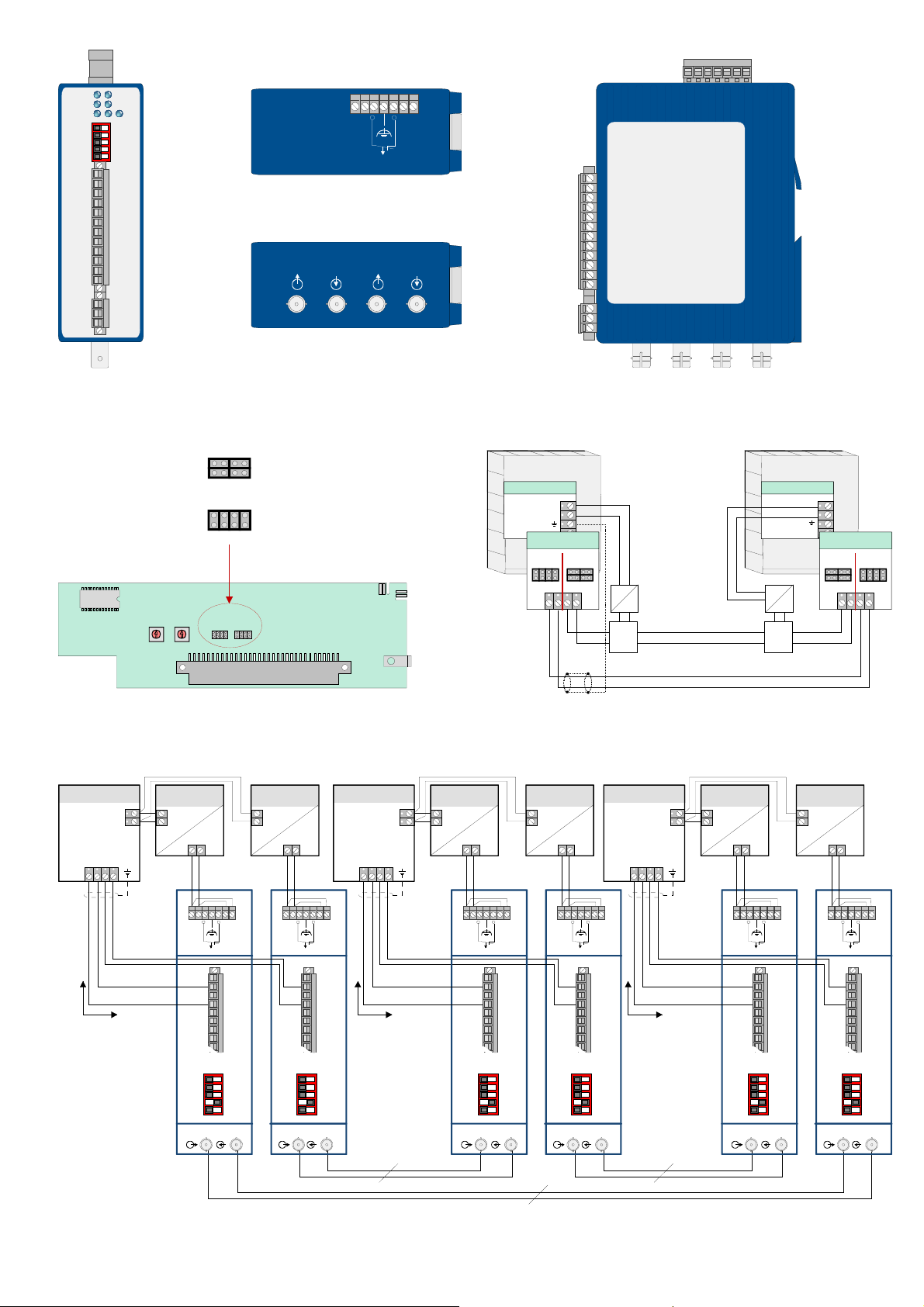
Abb.1: Lage der Klemmen / Port-Anschlüsse und LED Anzeigen
Fig. 1: Localization of the terminals / ports and LED indicators
Einstellung der Steckbrücken für den LWL-Anschluss
Jumper setting for FOC wiring
Einstellung der Steckbrücken für den Anschluss von
konventionellen Kupferkabeln (werkseitige Einstellung)
Jumper setting for conventional copper cable wiring
(factory setting)
S2
S1
0
1
1
9
2
2
8
3
3
7
4
4
6
5
DC/DC-converter
781335
+ 12 V DC
+
+ 24 V DC
+-
X4 X5
®
-Mikromodul (Beispiel)
®
micro module (example)
Spannungskonverter/
DC/DC-converter
781335
+ 12 V DC
+
+ 24 V DC
+-
0
9
8
7
6
5
Abb.2: Lage der Steckbrücken X4/X5 auf dem essernet
Fig. 2: Localization of the jumper X4/X5 on the essernet
BMZ 1 / FACP 1
0 V / GND
+ 12 V DC
essernet®-Mikromodul
Anschlußtechnik
®
essernet
micro module
terminal card
1234
Spannungskonverter/
BMZ 2 / FACP 2
0 V / GND
+ 12 V DC
essernet®-Mikromodul
Anschlußtechnik
®
essernet
micro module
terminal card
1234
Spannungskonverter/
DC/DC-converter
781335
+ 12 V DC
-
+
+ 24 V DC
+-
Zentrale 1
Panel 1
Basismodul /
Basic module
0 V / GND
+ 12 V DC
essernet®-Modul /
essernet
®
module
Basismodul /
Basic module
X4 X5
4 3 2 1
Abb.3 Prinzipdarstellung mit erforderlicher Einstellung der Steckbrücken X4/X5
Fig. 3: Schematic diagram with required jumper settings X4/X5
Spannungskonverter/
DC/DC-converter
781335
+ 12 V DC
-
+
+ 24 V DC
+-
DC
DC
Lichtwellen-Leiter (LWL)
Fibre optics cable (FOC)
LWL
FOC
Konventionelle essernet
BMZ 3 / FACP 3
0 V / GND
+ 12 V DC
essernet®-Mikromodul
Anschlußtechnik
®
essernet
micro module
terminal card
1234
Conventional essernet
Spannungskonverter/
DC/DC-converter
781335
+ 12 V DC
-
+
®
-Verdrahtung
®
wiring
+ 24 V DC
+-
DC
LWL
FOC
DC
Zentrale 2
Panel 2
0 V / GND
+ 12 V DC
Spannungskonverter/
DC/DC-converter
781335
+ 12 V DC
-
+
essernet®-Modul /
®
module
essernet
X4 X5
4 3 2 1
+ 24 V DC
+-
max. 2 m
Abb. 5: Anschlussbeispiel Lichtwellenleiter
Fig. 5: Wiring example Fibre optic cable
0V
0V
+24V (P1)
+24V (P2)
FAULT
RT+
Port 1
K1+
K1+
K1-
K1RTRTK2K2-
S3
S0
S1
S2
S4
01
/
®
®
LWL-Konverter für essernet
Port 3
Î
konventionelle Kabelstrecke
Î
conventional wiring
0V
0V
+24V (P1)
+24V (P2)
FAULT
RT+
Port 1
K1+
K1+
K1-
K1RTRTK2K2-
S3
FOC converter for essernet
S0
S1
S2
S4
01
/
max. 2 m
®
®
FOC converter for essernet
LWL-Konverter für essernet
Port 2
LWL / FOC LWL / FOC
+24V (P2)
RT+
K1+
K1+
K1-
K1RTRTK2K2-
S0
S1
S2
S3
S4
0V
FAULT
01
Port 3
0V
Port 1
+24V (P1)
/
®
LWL-Konverter für essernet
®
FOC converter for essernet
LWL / FOC
RT+
K1+
K1+
K1-
K1RTRTK2K2-
S3
+24V (P2)
S0
S1
S2
S4
0V
FAULT
01
Port 2
0V
Port 1
0V
0V
+24V (P1)
/
max. 2 m
®
®
FOC converter for essernet
LWL-Konverter für essernet
+24V (P2)
RT+
K1+
K1+
K1-
K1RTRTK2K2-
S0
S1
S2
S3
S4
FAULT
01
Port 1
+24V (P1)
/
®
®
FOC converter for essernet
LWL-Konverter für essernet
Port 3
+24V (P2)
RT+
K1+
K1+
K1-
K1RTRTK2K2-
S0
S1
S2
S3
S4
0V
FAULT
01
Port 2
0V
Port 1
+24V (P1)
/
®
®
FOC converter for essernet
LWL-Konverter für essernet
 Loading...