

Essential Trading DS-1400, DS-1800 Installation Manual

DS-1400/1800 Media Gateway
Installation Guide
TTHHEE PPOOSSSSIIBBIILLIITTIIEESS AARREE
99 AAuussttiinn DDrriivvee,, MMaarrllbboorroouugghh,, CCTT 0066444477 ((886600)) 229955-
-88110000 wwwwww..eesssseennttiiaalltteell..ccoomm
EENNDDLLEESSSS..
ssaalleess@@eesssseennttiiaalltteell..ccoom
m

Table of Contents
Introduction .............................................................................................3
Parts List .................................................................................................3
Physical Overview...................................................................................4
Hardware Connections............................................................................6
Windows XP Audio Device Hardware Configuration............................... 7
Specifications........................................................................................ 14
Analog Port Pin Out............................................................................14
DS-1400/1800 Hardware Product Limited Warranty.............................15
Introduction
DS-1400/1800 Installation Guide Rev 05.12 Page 2 of 15 Essential Trading Systems Corp.

The DS-1400/1800 Media Gateway is a 4/8-port analog to IP device that provides full duplex
audio communication over a customer's existing network (recommended) or the internet in a 1
Rack Unit enclosure. The DS-1400/1800 utilizes Windows application software for secure
network connectivity and ETC’s Viper VoIP software powered by Twisted Pair’s WAVE software
as transport medium.
Parts List
DS-1400 (Figure A) DS-1800 (Figure AA), AT 1510-8C-BK (10’ 568b patch cord) (Figure B),
HW-500 (Rack screws 10-32x3/8” (Figure C), 18-3 gauge black PVC jacketed power cord
(Figure D)
Figure A
Figure AA
Figure B Figure C Figure D
Physical Overview
DS-1400/1800 Installation Guide Rev 05.12 Page 3 of 15 Essential Trading Systems Corp.
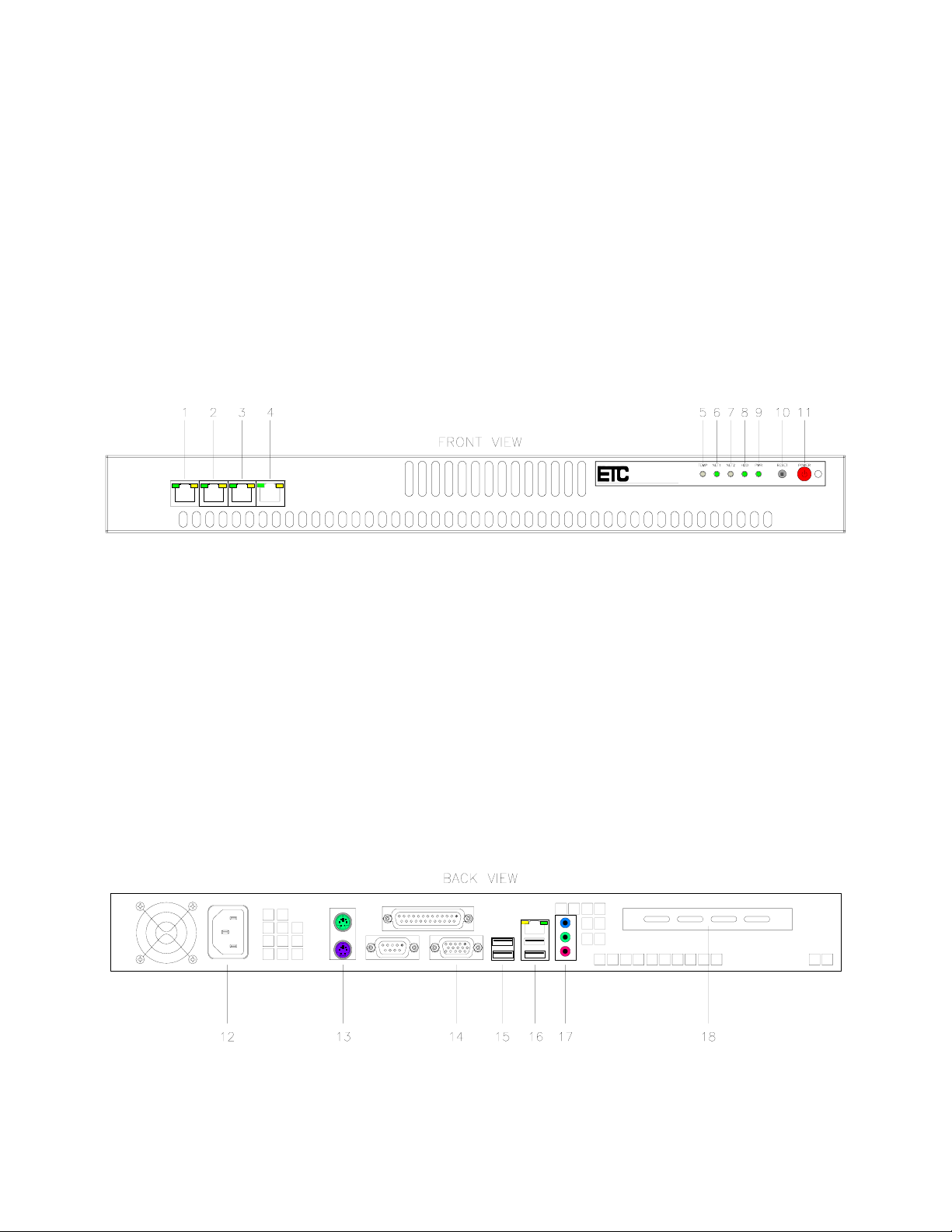
Note: The DS-1800 has EIGHT (8) RJ45 ports instead of only FOUR (4) as shown in (Figure E).
Front View (Figure E):
(1-4) Analog Ports – RJ45 EIA/TIA 568b, balanced, transformer isolated, 600 Ohm, full duplex
(5) TEMP -
(6) NET 1 -
(7) NET 2 (8) HDD – Provides front panel indication of Hard Drive activity
(9) PWR – Provides front panel indication of the unit’s on/off status
(10) RESET – Provides front panel access to manually reset the gateway
(11) POWER – Power ON/OFF switch
Figure E
Back View (Figure F):
(12) 120 VAC power connection
(13) Keyboard and Mouse connection
(14) VGA port connection to local monitor or KVM
(15) Spare USB ports
(16) NIC (Ethernet) and primary USB ports
(17) On board sound audio I/O (Not Used)
rd
(18) Expansion slot to allow installation of 3
party add on cards when applicable
Figure F
.
“E & M” Functionality
DS-1400/1800 Installation Guide Rev 05.12 Page 4 of 15 Essential Trading Systems Corp.

“M” Lead (Tx): Both the VG-1400 and VG-1800 have the “M” Lead option of adjustable timedelay PPuusshh TToo TTrraannssmmiitt ((PPTTTT)) ccoonnttaacctt cclloossuurree. The “M” Lead option becomes critical in
matching transmit delay to equipment key-up time. Each of the four channels has a dedicated
16 position adjusting switch (Figure H). Included on the back of the board is a label (Figure I)
showing the switch adjustment position to time delay correlation (Figure J). The PTT Dry
Contact is a solid state non-polarized Normally Open (NO) relay. Specification maximum values
are 100VDC max. Open; 150mA current and 8
Ω max resistance Closed.
Position Delay - mS
0 45
1 90
2 130
3 180
4 220
5 260
6 300
7 350
8 400
9 450
A 480
B 530
C 570
D 620
E 660
F 700
Figure G Figure H Figure I
“E” Lead (Rx): Only the VG-1400 has the option of requiring a switch TToo EEnnaabbllee RRxx or having
AAllwwaayyss AAccttiivvee RRxx..
noise can be interpreted as an analog signal. Thus, having Rx disabled unless the VG-400
receives a viable switch signal avoids noise. Pair 3 is designated as “E” Lead Rx with Pin 3 as
Ground and Pin 6 as logic level +3.3VDC. Pulling or “Pinning Up” Pin 3 to Pin 6 is what enables
Rx to activate. The DS-1400 uses jumper JP1 (Figure J) to globally enable or disable this
feature.
• By positioning JP1 in “E & M” mode, the board
requires a switch signal TToo EEnnaabbllee RRxx.
• By positioning JP1 in “On” mode, which is the factory
default setting (Figure J), the board does not
switch signal and is AAllwwaayyss AAccttiivvee RRxx..
Figure J
To access these settings, remove the top cover of the DS-1400/1800.
The “E” Lead option becomes critical in LMR situations where background
require a
DS-1400/1800 Installation Guide Rev 05.12 Page 5 of 15 Essential Trading Systems Corp.
 Loading...