

Essence Technology EIG-8O-4S, EIG-8O-/4, EIG-8O-4S/4, EIG-8O-8S Administration Manual

Essence
®
Technology
EIG-8O Gateway Administration Guidelines
Version

12/5/2006 EIG-8O Gateway Administration Guidelines MAG-06008 Rev. A
T A BLE OF CONTENTS
EIG-8O Gateway Administration Guidelines............................................................................................i
Version.....................................................................................................................................................i
1 Introduction.......................................................................................................................................1
1.1 Overview.......................................................................................................................1
1.2 Features........................................................................................................................1
1.3 Hardware Platform........................................................................................................3
1.3.1 Physical................................................................................................................3
1.3.2 System Specifications..........................................................................................4
2 Preparation for Installation................................................................................................................5
2.1 Safety Check.................................................................................................................5
2.2 Installation Environment................................................................................................5
2.2.1 Temperature/Humidity..........................................................................................5
2.2.2 Dust Control and Air Flow.....................................................................................5
2.2.3 Interference and Lightening Hazard.....................................................................5
2.2.4 Installing EIG-80...................................................................................................6
2.3 Inspecting EIG-80 .........................................................................................................6
3 Installation.........................................................................................................................................7
3.1 Installing EIG-80............................................................................................................7
3.2 Connecting the Cables..................................................................................................7
3.2.1 Connecting the Ethernet Port...............................................................................7
3.2.2 Connecting FXS Cable.........................................................................................9
3.2.3 Connecting FOX Cable ........................................................................................9
3.3 Connecting the Power Supply.......................................................................................9
3.4 Final Checks after Installation.......................................................................................9
4 Function Description.......................................................................................................................11
4.1 Registration.................................................................................................................11
4.2 System Configurations................................................................................................12
4.3 Set up the Phone Numbers.........................................................................................14
4.4 MGCP Setting.............................................................................................................15
4.5 SIP Setting..................................................................................................................18
4.6 Network Configuration ................................................................................................19
4.7 Supplementary Features.............................................................................................21
ii

12/5/2006 EIG-8O Gateway Administration Guidelines MAG-06008 Rev. A
4.7.1
Setting up the Feature Keys...............................................................................21
4.7.2 Set up All Forward..............................................................................................25
4.7.3 Set up Busy Forward..........................................................................................26
4.7.4 Set up No Answer Forward................................................................................26
4.7.5 Set up Fashion Ring...........................................................................................27
4.7.6 Set up Hotline.....................................................................................................27
4.8 Dialing Plan and Routing Table...................................................................................28
4.8.1 Set up the Dialing Plan.......................................................................................28
4.8.2 Set up the Routing Table....................................................................................29
4.9 Set up the FXS Ports ..................................................................................................33
4.10 Set up the FXO ...........................................................................................................36
4.11 Advanced Options.......................................................................................................38
4.11.1 System Advanced Options.................................................................................38
4.11.2 Advanced FXO Options......................................................................................41
4.11.3 Advanced FXS Options......................................................................................42
4.11.4 Advanced IP Options..........................................................................................43
4.11.5 Advanced SIP Options.......................................................................................44
4.11.6 Advanced IMS Options.......................................................................................47
4.12 Log Information...........................................................................................................49
4.12.1 Call Status Information.......................................................................................49
4.12.2 Resources Information.......................................................................................50
4.12.3 Message Information..........................................................................................50
4.12.4 Error Information ................................................................................................51
4.12.5 Startup Information.............................................................................................51
4.12.6 Clear Message Information................................................................................52
4.13 System Tools...............................................................................................................52
4.13.1 Restore Factory Setting......................................................................................52
4.13.2 Software Update.................................................................................................56
4.13.3 Change Password..............................................................................................57
4.13.4 Restart Gateway.................................................................................................57
4.13.5 Help....................................................................................................................58
4.14 Exit ..............................................................................................................................58
iii

12/5/2006 EIG-8O Gateway Administration Guidelines MAG-06008 Rev. A
1 Introduction
1.1 Overview
EIG-8O is a multi-purpose VoIP gateway product series designed with the needs of service providers
and enterprises in mind. With EIG-8O gateways, service providers can provide telephony and fax
services to subscribers using many access methods such as FTTB, HFC, and ADSL. Enterprises can
use the EIG-8O’s traditional PBX interface to implement voice VPN solutions with their private IP or
public VPN networks. EIG-8O can also serve as a remote SIP terminal for IP-PBX solution.
EIG-8O has a variety of models. Each model can be customized to have different number of FXS port s
and FXO ports. It shares the same software sy stem as other Essence’s VoIP products (MX100 and
MX100-TG) and therefore keeps the advantage s in f unctionality, quality, and compatibility of Essence
products. In hardware EIG-8O uses Motorola’ s MPC852 as the Central Processing Unit, and TI C5509
high efficiency chip to process voice and faxes. The powerful ha rdware equipment ensures EIG-8O to
send signaling and IP packet s in different channels even when traffic is at the peak, thus support s
major functions such as voice codec (G.711, G . 729A, G.723.1, GSM and iLBC) and echo cancellation.
This manual is mainly about EIG-8O installation and web configuration. Please note that af ter you have
made changes to many of the parameters on EIG-8O Web Configuration p age and clicked the Submit
button, you may get messages like "Submission is successful. Please restart the system to make the
changes effective." You need to restart EIG-8O u sing the instruction in section 4.13.4.
EIG-8O also has the capability to restore the default settings. Just click the Restore Default button.
EIG-8O configuration parameters have brief descriptions. To find o ut, just point your mou se o v er the
parameter.
1.2 Features
EIG-8O has the following features:
․ It supports SIP/MGCP protocols
․ It supports route selection (it can route a call or direct it to the internet according to the called
number)
․ It supports RADIUS based CDR protocol
1

12/5/2006 EIG-8O Gateway Administration Guidelines MAG-06008 Rev. A
․ It supports gain adjustment to FXS/FXO ports
․ It supports the intrusion into NAT through a STUN server
․ It supports traditional terminal devices, including phones, fax, and PBX
․ It supports a variety of supplementary services such as All forward, Forward No Answer, Forward
Busy Line, Call waiting, and Distinctive Ring, etc.
․ It can obtain static IP address or capture mobile IP address through DHCP and PPPoE
․ It supports the traditional fax service using T.30 and T.38 formats
EIG-8O with FXO ports
It supports the following sinaling protocols:
․ SIP (Compliant to RFC 3261 and TISPAN)
․ MGCP
It supports the following codec:
․ G.711
․ G.723.1
․ G.729A
․ GSM
․ iLBC
․ G.168 Echo Cancellation
․ DTMF RFC2833 and T.38
2
12/5/2006 EIG-8O Gateway Administration Guidelines MAG-06008 Rev. A
1.3 Hardware Platform
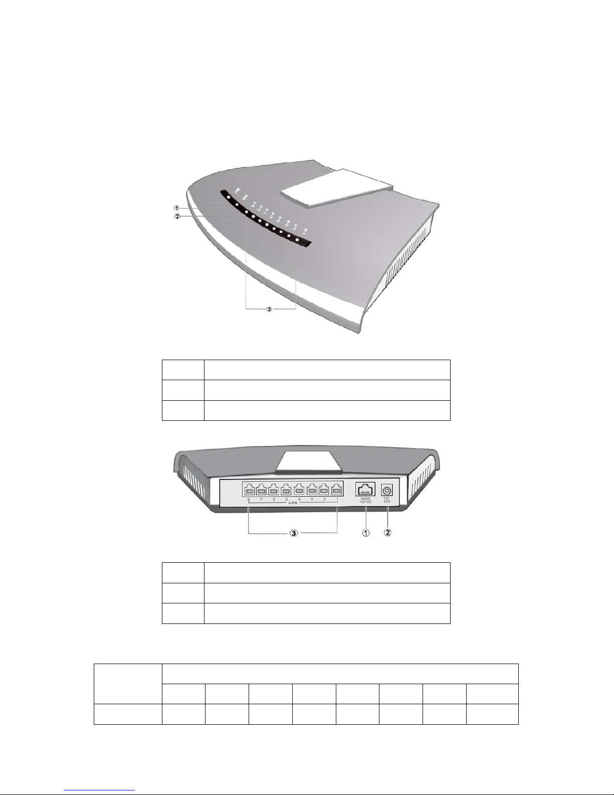
1.3.1 Physical
Figure 1. EIG-8O Front View
①
Power indicator (PWR). If lit, power is on
Ethernet port indicator. If lit, it is in operation
②
FXS/FXO indicators. The port number is lit when in use
③
Figure 2. EIG-8O Rear View
①
10/100 baseT Ethernet port
Power plug-in
②
FXS/FXO ports, a total of 8
③
Table 1. EIG-8O Configuration Options
RJ11 Port Configuration
Model
Number
1 2 3 4 5 6 7 8
EIG-8O-4S FXS1 FXS2 FXS3 FXS4 Null Null Null
Null
3

12/5/2006 EIG-8O Gateway Administration Guidelines MAG-06008 Rev. A
EIG-8O-8S FXS1 FXS1 FXS3 FXS4 FXS5 FXS6 FXS7 FXS8
EIG-8O-/4 FXO1 FXO2 FXO3 FXO4 Null Null Null Null
EIG-8O-4S/4 FXS1 FXS2 FXS3 FXS4 FXO1 FXO2 FXO3 FXO4
1.3.2 System Specifications
Internal Memory 32MB
Flash Memory 4MB
On-hook Battery -56V
Off-hook Battery -24V
Ringing Voltage 60V
REN Equivalence 5 for short loop ( 1000 feet), 3 for long loop (5000 feet)
Loop Current = or > 21 mA
Loop Resistance Up to 188 Ω
Level two surge protection. Can stand up to 1000V (10/100uS)
power surge
Surge Voltage
Max Line Length 1500 m
Off-hook Detection Loop Sta rt
Dialing DTMF
Input Voltage 12V DC
Input Current 1.5Amp (Max)
Power Consumption 15Watt (Max)
Operation Temperature 0 ~ 40°C
Non Operation Temperature -25 ~ 70°C
Operation Humidity 5 ~ 95% (Non Condensed)
Dimension (H×L×W) 300x190x45 mm
Weight 800g
4

12/5/2006 EIG-8O Gateway Administration Guidelines MAG-06008 Rev. A
2 Preparation for Installation
To avoid any body injury and device damage, please read this chapter carefully before the installation.
2.1 Safety Check
Please follow the safety guidelines when installing EIG-8O.
․ Keep away from wet group and heat
․ Ensure safe use of electricity
․ Ensure to connect all the interface cables correctly
2.2 Installation Environment
2.2.1 Temperature/Humidity
The EIG-8O installation room must maintain normal temperature and humidity.
If the room temperature exceeds the specified maximum temperature, it will shorten the live of the
electrical insulation material. If the room humidity exceeds the specified humidity, EIG-8O may
experience electrical static shock and shrinkage of electric insulation material in the metal package. It
may also cause metal corrosion. All these will drastically shorten the life span of the EIG-8O. It is
strongly recommended that user control the environmental temperat ure between 0 ºC and 40ºC and
humidity between 5% and 95% (none condensing).
2.2.2 Dust Control and Air Flow
Dust falls on the EIG-8O might cause intermittent failure in electrical connections. It may cause long
term damage to EIG-8O will cause equipment failure and shorten equipment life span. Th erefore,
EIG-8O needs to have ample air flow in front of the EIG-8O air intake and outta ke for proper heat
exhaust.
2.2.3 Interference and Lightening Hazard
EIG-8O may experience various types of EMI hazards in operation and its performance may be
5

12/5/2006 EIG-8O Gateway Administration Guidelines MAG-06008 Rev. A
impacted. To reduce those hazards, it is suggested that:
․ Do not install EIG-8O close to high power wireless equipment, RA DAR transmission site, and
high frequency high electric current devices.
․ EIG-8O comes with Level 2 lightening protection. Its operation site requires Level 1 lightening
protection.
․ EIG-8O must have its own power source and should be electrical interference free
․ Ensure proper grounding
2.2.4 Installing EIG-80
When installing the EIG-8O please make sure EIG-8O is secured and has am ple space for air flow.
2.3 Inspecting EIG-80
After the installation preparation is completed, the sh ipping package can be opened to examine all the
items in the package. The list of items for the EIG-8O is shown in
Table 2.
Table 2. EIG-8O Basic Configuration and Accessories
Model Number Qty Description
EIG-8O-4S,EIG-8O-8S,
EIG-8O-/4, EIG-8O-4S/4
1 Each EIG-8O may have 4 FXS ports, or 8 FXS ports, or
4 FXO ports, or 4 FXS/FXO ports. You need to examine
carefully to make sure what you receive is what you paid
for.
MX-PWR10-V01-00 1 EIG-8O DC adaptor 12V 1.5A.
MX-CBL00-0005 1 5 meter Ethernet cable, 1.5m in length.
MX-CBL00-0011 1 EIG-8O power cord.
Note: It is suggested that users carefully examine the content of the shipping p ackage a ccording to the
sales contract. If there is any question or problem, please contact our customer service
department.
6

12/5/2006 EIG-8O Gateway Administration Guidelines MAG-06008 Rev. A
3 Installation
3.1 Installing EIG-80
Since EIG-8O is small, you can put it to a clean and flat workspace. Please make sure it is secured and
has ample space for air flow.
3.2 Connecting the Cables
3.2.1 Connecting the Ethernet Port
EIG-8O has one 10/100 Base-T Ethernet port with RJ45 connector. It is equipped with LED status
display. Besides voice packet, this port can also manage, maintain, and control the information flow .
The Ethernet Cable needs to be carefully made to ensure IP data a nd voice quality. The following is the
Ethernet cable making scheme:
1. A user can use a proper cable peeling cutter to peel away 3cm skin of a CA T-5 cable. What is left
is shown in the following figure.
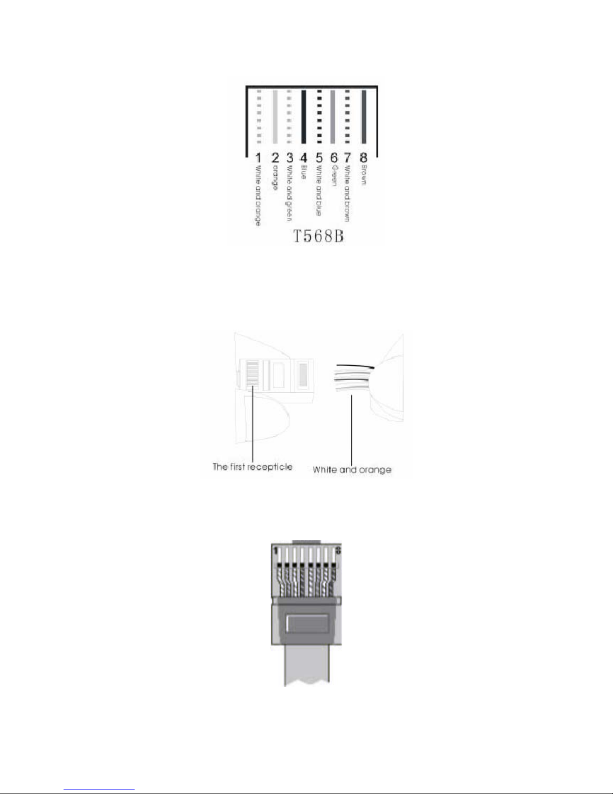
2. Twisted pairs. Currently, the most commonly used standard wiring scheme is EIA/TIA T568B
shown in Figure 3-2. In the wiring scheme, pin 1 and 2 are a p air, pin 3 and 6 are a pair, pin 4 and
5 are a pair and pin 7 and 8 are a pair. According to the Figure 3-2, twisted pairs line up with
colors (1: white orange,2: orange,3: white green,4:blue,5: white blue,6:green,7: white brown ,
8: brown). It is specially noted that the green and white green are separated by a pair of blue
wires. It is a common mistake to put green and white green close together, which will result in
interference and therefore lower transmission efficiency.
7
12/5/2006 EIG-8O Gateway Administration Guidelines MAG-06008 Rev. A
Figure 3. T568B wire pairing scheme
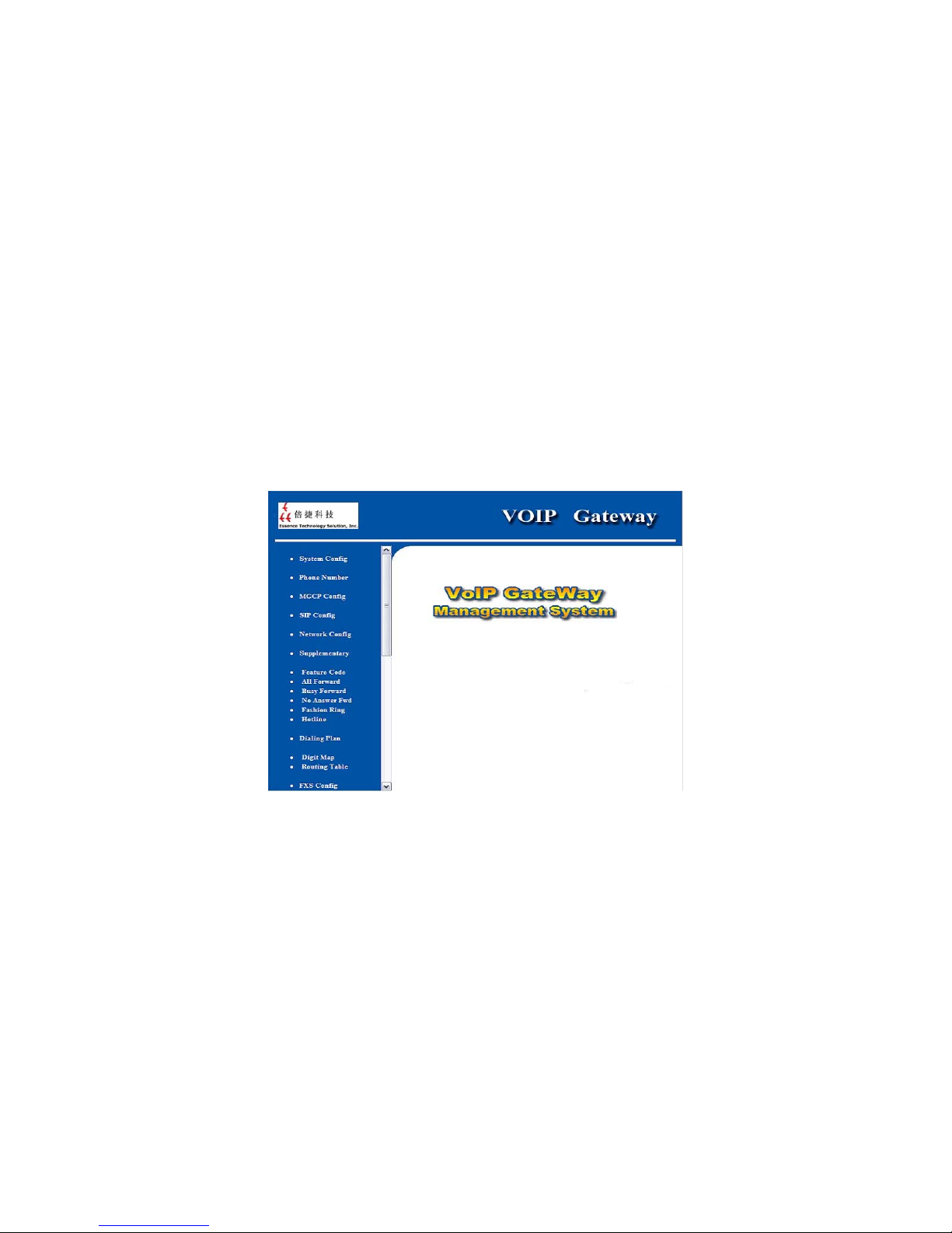
3. After lining up wires to the correct pin positions, trim all the twisted pairs with a cable cutter,
leaving 15mm leads exposed. Then follow Figure 3-3 by inserting wire s to their corre sponding pin
position in the plastic shell of RJ45 connector. Pin 1 will house white orange wire, etc.
Figure 4. RJ 45 Wiring
4. After wires have been properly inse rted into RJ45 connector; a cramping tool can secure the
wires to the connector and make connections to the metal pins as shown in
Figure 5.
Figure 5. Finished RJ 45
8

12/5/2006 EIG-8O Gateway Administration Guidelines MAG-06008 Rev. A
Since this is a direct connection, the connector for the other end of the cable can be made the same
way using RJ45 connector.
After the Ethernet cable is ready, Connect one end of the cable to EIG-8O’s WA N port and the other
end to a switch or router. Check the Ethernet status display: light or flash means activity.
3.2.2 Connecting FXS Cable
EIG-8O have FXS ports that connect to phones.
Connect one end of the RJ1 1 cable to the EIG-8O FXS port, and conne ct the other end to a phone, fax,
or PBX.
3.2.3 Connecting FOX Cable
Certain EIG-8O products, like EIG-8O-4 or EIG-8O-4S/4, have FXO ports that connect to PBX or
PSTN.
Connect one end of the RJ11 cable to the EIG-8O FXO port, and connect the other end to a PBX or
PSTN line.
3.3 Connecting the Power Supply
Before plugging EIG-8O into the power outlet, it is suggested that tri-phase power outlet be used and
grounding be properly connected.
Please follow the procedure when connecting to the power source:
Plug the DC head of the power adaptor into EIG-8O’s DC input socket.
Plug the AC head of the power adaptor into the power outlet of 110V or 220V.
Check to see if the PWR LED indicator is lit. If PWR LED is lit, everything is normal. If not, repeat Steps
1 to 2.
Note: If power up fails repeatedly, please contact Essence technical support. Do not attempt to open
EIG-8O to fix any problems.
3.4 Final Checks after Installation
After installing EIG-8O and before it is powered on, please make sure of the following:
․ There is ample air space around EIG-8O for heat exhaustion.
․ Power cord is standard and matches the required electric voltage.
9

12/5/2006 EIG-8O Gateway Administration Guidelines MAG-06008 Rev. A
․ Make sure the ports are connected to the right devices.
Note: It is very important to recheck all the installation work to ensure EIG-8O to function properly and
trouble free.
10
12/5/2006 EIG-8O Gateway Administration Guidelines MAG-06008 Rev. A
4 Function Description
4.1 Registration
1. Power up the EIG-8O. EIG-8O uses DHCP by default, and will auto matically detect an IP address.
If you cannot get the IP address (when you connect to the computer directly), use the default IP
address “192.168.2.218”. Af ter power up (when cu st omer line L CD stops flashing), if the gateway
uses MGCP protocol, it will tell the IP addre ss to any first off-hook user. If using SIP protocol, you
can press “##” to get the IP address through any customer line at any time.
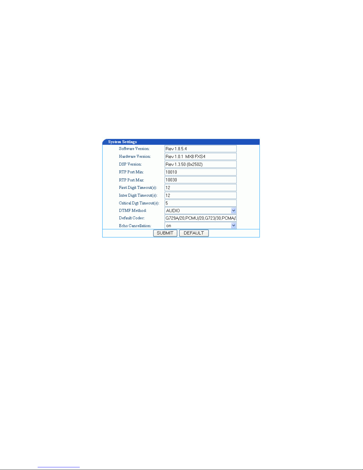
2. Open Internet Explorer in the computer which is connected to the same network as EIG-8 O.
3. Enter EIG-8O IP address(for example: 192.168.2.21 8 ), and the web interface will display as
shown in
Figure 6.
Figure 6. VoIP Gateway System Configurations Interface
EIG-8O has two levels of management: the administrator level (default password: voip) and the
operator level (default password: operator). Administrator level has higher access privilege, and is
allowed to change password for all users at all levels. Operator level has lower access privilege, and
certain options are not available including network configurations, password management and restore
factory default settings.
EIG-8O allows multiple users to log on at the same time. Only the first user logged on with highest
privilege is able to change configurations. The rest can only monitor configurations.
Note: After a user logs on, he/she will be automatically logged of f if there is no act ivity for more than 10
11
12/5/2006 EIG-8O Gateway Administration Guidelines MAG-06008 Rev. A
minutes. After that, a user n eeds to log on again.
Note: Af ter complete configuration, a user must completely log out instead of just closing the browser.
This will elevate the access level of the next logged on user so he/she will be able to ch ange the
configurations.
4.2 System Configurations
Click System Configuration link on the left of Figure 6, and you will see what is shown in Figure 7.
Figure 7. System Configuration Interface
Software Version
The Software Version field displays EIG-8O software version. Software automatically updates this
field whenever a new software version is loaded. You can not change this field.
Hardware Version
The Software Version field displays EIG-8O software version. Software automatically updates this
field whenever a new software version is loaded. You can not change this field.
DSP Version
The Software Version field displays EIG-8O software version. Software automatically updates this
field whenever a new software version is loaded. You can not change this field.
RTP Port Min
In the RTP Port Min field, enter the minimum value of sending and receiving RT P port.
RTP Port Max
In the RTP Port Max field, enter the maximum value of sending and receiving RTP port. A VoIP call
uses two RTP ports: one for RTP and the other for RTCP. If EIG-8O has 4 lines(FXS), then the RTP
12

12/5/2006 EIG-8O Gateway Administration Guidelines MAG-06008 Rev. A
port is set to 8 ports at least. If RTP has less than 8 ports,4 lines can not be used at the same time.
EIG-8O adopts 8 FXS ports at the most. So it is highly recommended you set RTP to 16 ports. Default
is 10010 ~ 10030. You do not need to change it.
First Digit Timeout
In the First Digit Timeout field enter the time (in second) allowed for the dialing of the first digit. When
a line goes off-hook, if within the time specified here the first digit has not been dialed, EIG-8O will treat
this as an abandoned call and will indicate to the caller to place the phone on hook. Th e default value
is 12 seconds.
Inter Digit Timeout
In the Inter Digit Timeout field enter the time (in second) allowed for the dialing of the middle digits.
Counting from the last digit dialed, if within the time specified here no digit has been dialed, the system
will send the dialed digits out. The default value is 12 second.
Dialing Finish
In the Dialing Finish field enter the time (in second) for finished dialing. This parameter is used in
conjunction with x.T in the dialing rule. After the specified head of the number in the rule has been
dialed, if within the time specified here no digit has been dialed, EIG-8O will send the dialed number
out. The default value is 5 seconds. For example, there is 021.T in the dialing rule. After the caller dials
021, if within the specified time (for example, 5 seconds) no digit has been dialed, 021 will be sent out.
DTMF Mode
In the DTMF Mode field select the transmission mode. This para meter is used to set DTMF signal
transmission mode. Options are Audio mode, 28 33 mode, and INFO mode. The d efault setting is Audio
mode. Audio mode is a transparent transmit mode; INFO mode is information transmit mode; 2833
mode is a RTP data p acket transmit mode.
Default Codec
In the Default codec field select the codec EIG-8O supports. EIG-8O support G729A/20, G723/30,
PCMU/20, PCMA/20, GSM, iLBC codec as well as manifold encoding modes at the same time.
Multiple values are demarked by commas. When manifold encoding mode is selected, the gate way will
process the communication by selecting the encoding mode front to back, which is supported by both
sides.
Table 3. Codes supported by the VoIP Gateway
Supported Codec Codec Mode Time Interval of RTP Packets
Transmission (unit: ms)
G729A/20
G.729A 20
G723/30 G.723 30
13
12/5/2006 EIG-8O Gateway Administration Guidelines MAG-06008 Rev. A
PCMU/20 G.711 20
PCMA/20 G.711 20
iLBC/30 iLBC 30
GSM/20 GSM 20
Echo Cancellation
In the Echo cancellation, select on to invoke echo cancellation and off to close echo cancellation.
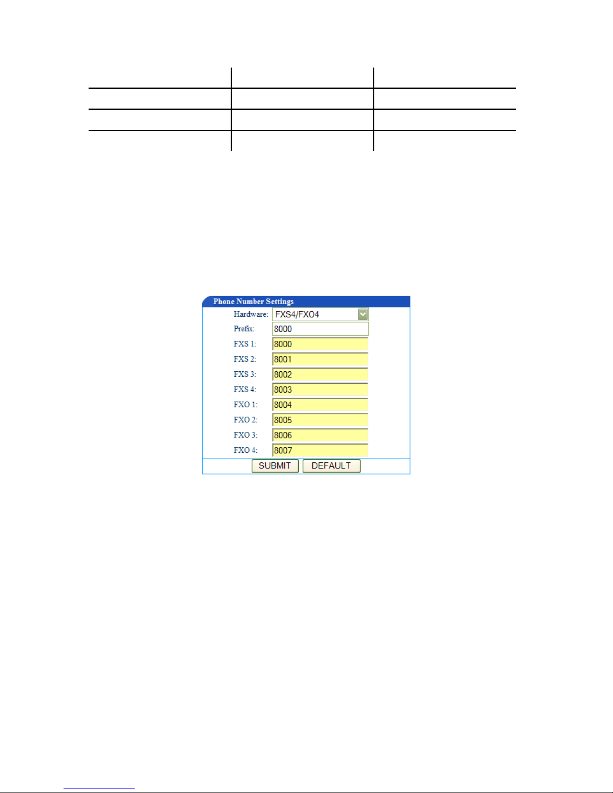
4.3 Set up the Phone Numbers
Click Phone Number link on the left of Figure 6, and you will see what is shown in Figure 8.
Figure 8. Phone Number setting screen
Hardware
Leave the Hardware field as it is. EIG-8O has more than one model, and the model number is set
through the software. This parameter is already predefined by the manufacturer. You do not need to
change it.
Prefix
In the Prefix field enter a prefix number which is for fast setting for serial number. You can leave it
blank from FXS2 to FXO4. When FXS1 uses this prefix number, F XS2 uses FXS1 number plus 1, and
so on and so forth.
When you set EIG-8O to MGCP gateway, the value of the prefix should be set to aaln/0 or aaln/1. If
MGCP call agent starts from “0”, then use aaln/0; if MGCP call agent starts from”1”, then use aaln/1.
When you set EIG-8O to SIP gateway, the value of the prefix should be the first number of the serial
14
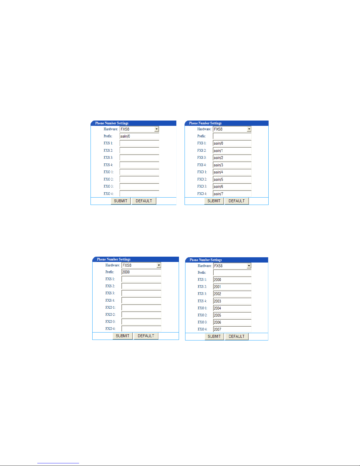
12/5/2006 EIG-8O Gateway Administration Guidelines MAG-06008 Rev. A
phone number which the registry server assigns to the gateway. For example if the number of gateway
is 2002007, then 200 should be entered in the Prefix field.
FXS (1~4) / FXO (1~4)
For the FXS lines, when the number is not a serial number or a serial number that is not incrementing
at order, you can manually enter the number for each FXS line. This gives user more flexibility.
Under MGCP mode
You can set the phone numbers either like shown in the following figures.
Figure 9-a Figure 9-b
Under the SIP mode
You can set the phone numbers either like shown in the following figures.
Figure 10-a Figure 10-b
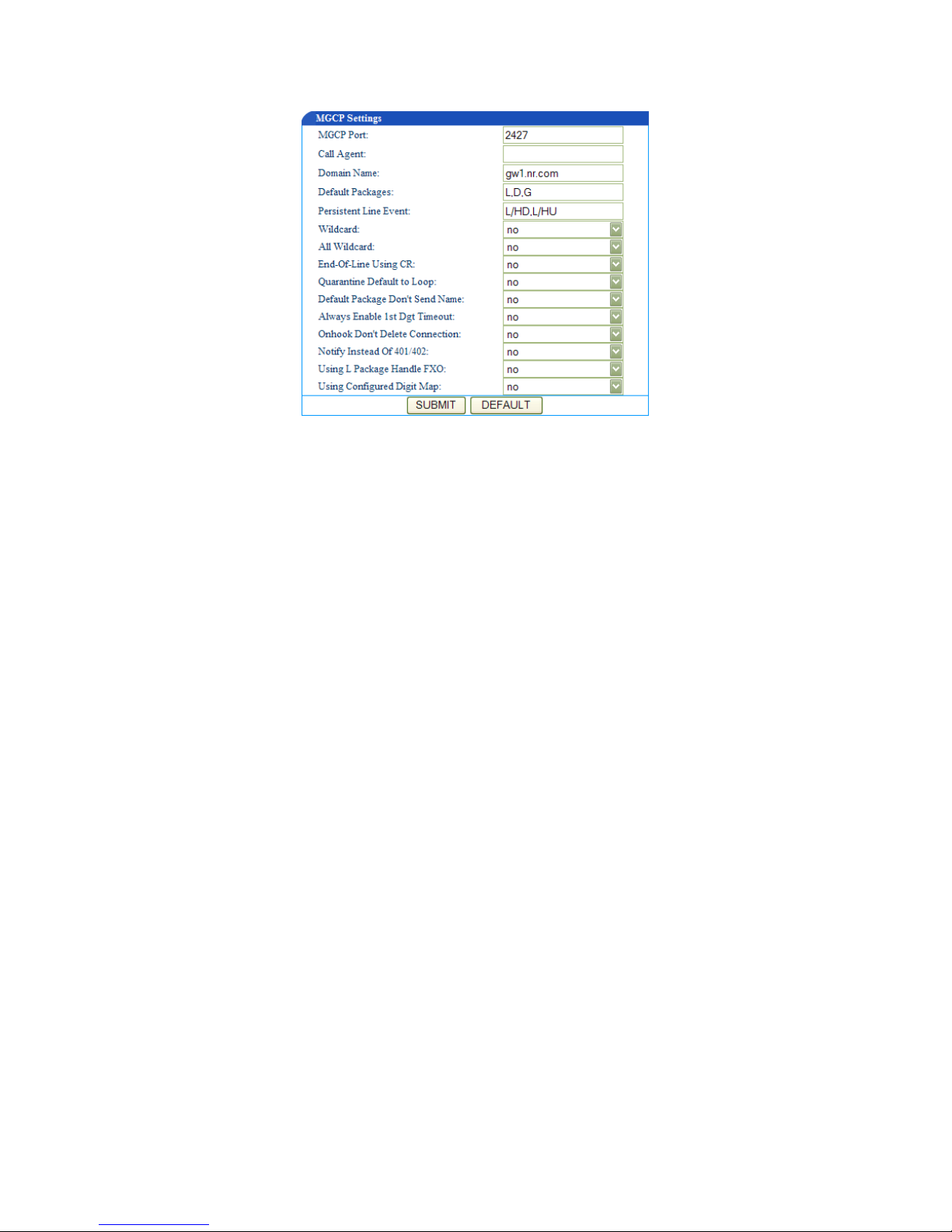
4.4 MGCP Setting
Click the MGCP Config link on the left of Figure 6. You will see Figure 11.
15
12/5/2006 EIG-8O Gateway Administration Guidelines MAG-06008 Rev. A
Figure 1 1. MGCP setting screen
MGCP Port
In the MGCP Port field enter EIG-8O gateway MGCP port number (example: 2427). You can use any
port number as long as it is not the same as other port numbers.
Call Agent
In the Call Agent field enter the call agent address and port number. Address and port number should
be separated by “:”. Address could be IP address or domain name. If you use domain name, you
should invoke DNS service and set parameter of DNS server in the Network Config page. A complete
sample configuration is like this: 202.202.2.202:2727; callagent.com:2727.
Domain Name
In the Domain Name field, enter the internet address or the IP address. Examples: test.essti.com;
[192.168.2.100].
Default Packages
In the Default Packages field enter all default packages. Use comma to separate each p ackage. The
default setting is L,D,G, which means Line Package, DTMF Package, and Generic Media Package.
Persistent Line Event
In the Persistent Line Event field enter all types of persistent line event. Use comma to separate each
line event. The gateway will report to call agent when it handles an event. The default setting is L/HD,
L/HU, and L/HF. L/HD means off-hook; L/HU means on-hook; and L/HF means hookflash.
Wildcard
In the Wildcard field select yes or no to indicate if EIG-8O will put the fixed prefix when it registers
(such as :aaln/*).
16
 Loading...