

Page 1

We.R Family and Home Management Kit
We.R Control Unit (M8000C)
User Manual
Essence Home & Family Ltd.
www.essence-grp.com
© 2010 Essence Home & Family. Information contained within this document may change without notice, v0.3
Page 2

Contents
Welcome! ....................................................................................................................... 4
Radio frequency interference statement ..................................................................... 4
1 System Activation .................................................................................................. 6
2 Registration ............................................................................................................ 7
3 Installing We.R Application on your Mobile ......................................................... 7
4 We.R Applications – Control Your System Remotely .......................................... 9
4.1 Web Application ................................................................................................ 9
4.2 Mobile Application ........................................................................................... 10
5 Managing Devices ................................................................................................ 11
5.1 Web Application .............................................................................................. 11
5.1.1 Adding a New Device ............................................................................... 11
5.1.2 Removing Existing Device ........................................................................ 13
5.1.3 Editing Existing Device Details ................................................................. 14
5.1.4 Device Status ........................................................................................... 14
5.2 Mobile Application ........................................................................................... 14
6 Mounting and Activating Devices ....................................................................... 15
6.1 Mounting Camera............................................................................................ 15
6.2 Mounting Motion Detector ............................................................................... 15
6.3 Mounting Window / Door Sensors ................................................................... 17
6.4 Mounting Indoor Siren ..................................................................................... 18
6.5 Activating the Key Fob .................................................................................... 18
6.6 Buttons and Indications ................................................................................... 19
7 Managing Users .................................................................................................... 21
7.1 Web Application .............................................................................................. 21
7.1.1 Adding a New User .................................................................................. 21
7.1.2 Removing Existing User ........................................................................... 22
7.1.3 Editing Existing User Details .................................................................... 22
7.2 Mobile Application ........................................................................................... 22
7.2.1 Adding a New User .................................................................................. 22
7.2.2 Removing Existing User ........................................................................... 23
8 Arming and Disarming the System ..................................................................... 24
8.1 Arm ................................................................................................................. 24
Page 2 of 30
Page 3

8.2 Disarm ............................................................................................................ 25
9 Handling Alarms ................................................................................................... 26
9.1 Burglary Alarm ................................................................................................ 26
10 Watching Real-Time Videos ................................................................................. 27
10.1 Web Application .............................................................................................. 27
10.2 Mobile Application ........................................................................................... 27
11 History – Reviewing Past Events ........................................................................ 28
11.1 Web Application .............................................................................................. 28
11.2 Mobile Application ........................................................................................... 29
12 Troubleshooting ................................................................................................... 30
Page 3 of 30
Page 4

Welcome!
This manual will assist you in installing and using your new We.R Family and Home
Management Kit.
Soon, you will be able to use a web browser, mobile phone or key fob to monitor and
secure your premises with state-of-the art motion detection, image capture and
window/door sensors.
Should you need more in depth information on features and services, please
contact the We.R Family & Home Management Kit Support Desk at support@wer-
mic.com
Our Recommendations
In order to ensure proper installation and operation, please place the control unit
at least 2 meters away from other Family and Home Management Kit
components.
Keep the system components away from wet, hot & humid environments.
Temperature ranges:
o System with Lithium battery
Storage Ambient Temperature range: -20°C - 60°C
Operating Ambient Temperature range: -5°C - 60°C
Radio frequency interference statement
This equipment has been tested and found to comply with the limits for a Class B digital
device, pursuant to part 15 of the FCC Rules. These limits are designed to provide
reasonable protection against harmful interference in a residential installation. This
equipment generates uses and can radiate radio frequency energy and, if not installed
and used in accordance with the instructions, may cause harmful interference to radio
communications. However, there is no guarantee that interference will not occur in a
particular installation. If this equipment does cause harmful interference to radio or
television reception, which can be determined by turning the equipment off and on, the
user is encouraged to try to correct the interference by one or more of the following
measures:
Page 4 of 30
Page 5

Reorient or relocate the receiving antenna.
Increase the separation between the equipment and receiver.
Connect the equipment into an outlet on a circuit different from that to which the
receiver is connected.
Consult the dealer or an experienced radio/TV technician for help.
Essence Home & Family is not responsible for any radio or communication interference
caused by using other than specified or recommended cables and battery or by
unauthorized changes or modifications to this equipment. Unauthorized changes or
modification could void the user’s authority to operate the equipment.
This device complies with part 15 of the FCC Rules. Operation is subject to the following
two conditions:
1. This device may not cause harmful interference, and
2. This device must accept any interference received, including interference that may
cause undesired operation.
Page 5 of 30
Page 6
1 System Activation
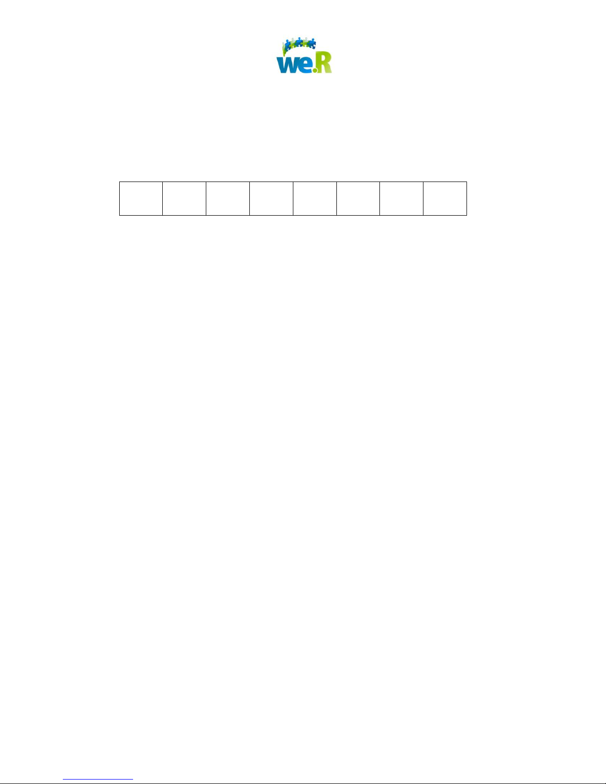
1. Open back of control unit and write the 8-digit alpha-numeric serial number here
for future reference :
2. Insert SIM card.
3. Plug the power cable into the control unit and into an electrical socket. (The light
on the front of the control unit will glow orange.)
4. Insert the square battery, replace the cover on the back of the control unit and
place the control unit on a flat surface.
5. Replace back cover, place on flat surface and wait for glowing light to turn from
orange to green before moving to next step. (The green light indicates that the
control unit is now activated. This can take approximately 5 minutes or less)
Page 6 of 30
Page 7
2 Registration
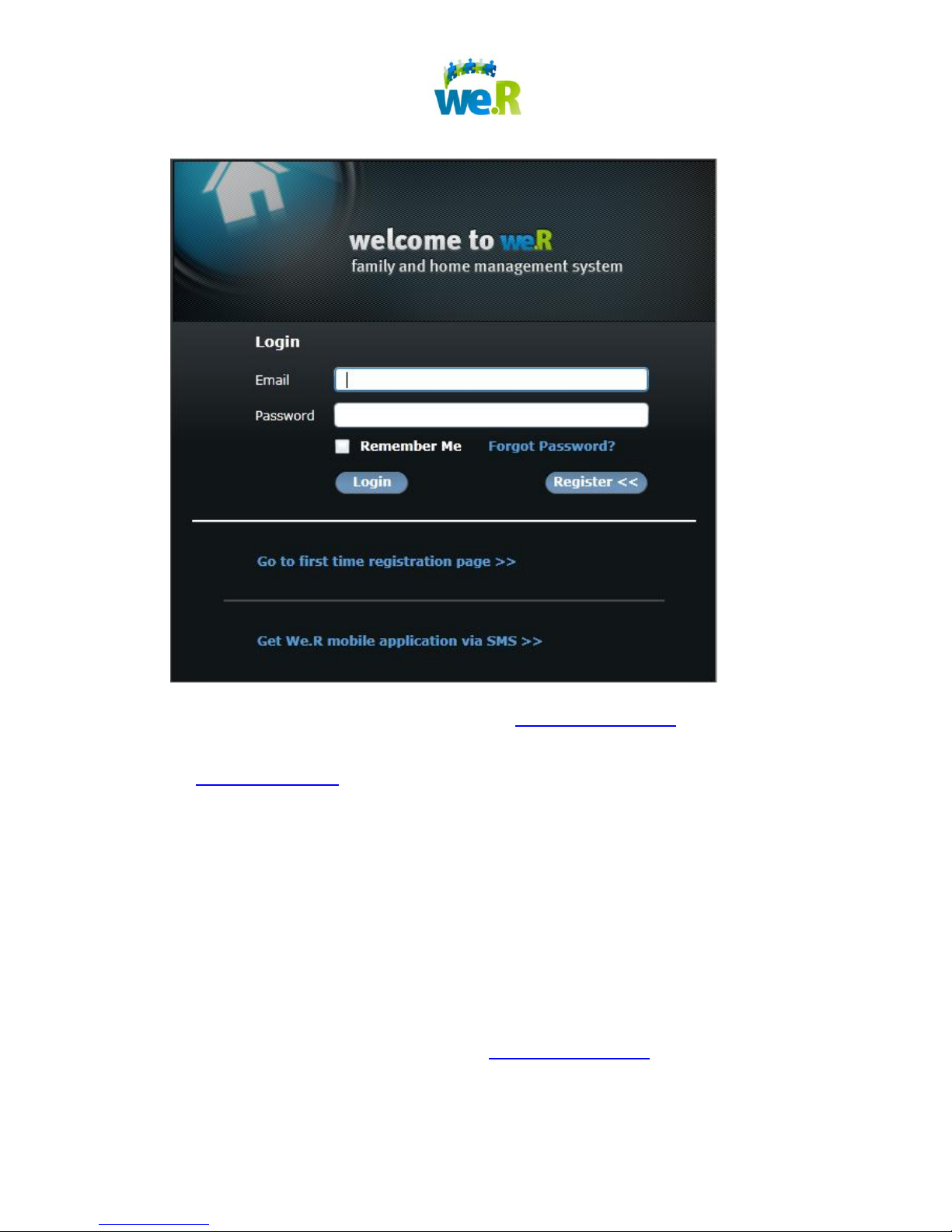
1. Open a PC-based web browser and go to www.wersystem.com.
2. If prompted, install the Microsoft "Silverlight" web application framework from
http://silverlight.net.
3. Click on the "Register" button, then click "Go to first time registration page" Enter
the 8-digit alpha-numeric serial number taken from the Control Unit during the
“System Activation” section.
4. Enter your personal details: Name, Password, Email, Mobile Phone Number
(including country and area codes), PIN code (for mobile phone usage) and click
"Finish".
3 Installing We.R Application on your Mobile
1. Using a PC-based web browser, go to www.wersystem.com.
2. Click “Register” and then “Get We.R mobile application via SMS”.
3. Enter the designated mobile phone number (“+”, “country code”, “area code”)
Page 7 of 30
Page 8
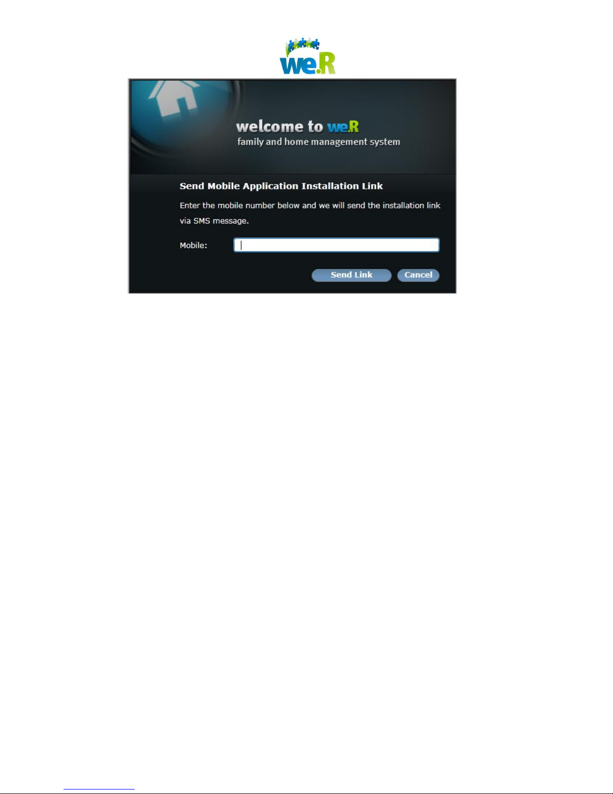
4. Click “Send Link”.
5. On the mobile phone, click on the link received within the SMS message and
follow the instructions on the phone to load the We.R mobile software.
6. If prompted where to install the application, select phone memory.
Page 8 of 30
Page 9
4 We.R Applications – Control Your System Remotely
4.1 Web Application
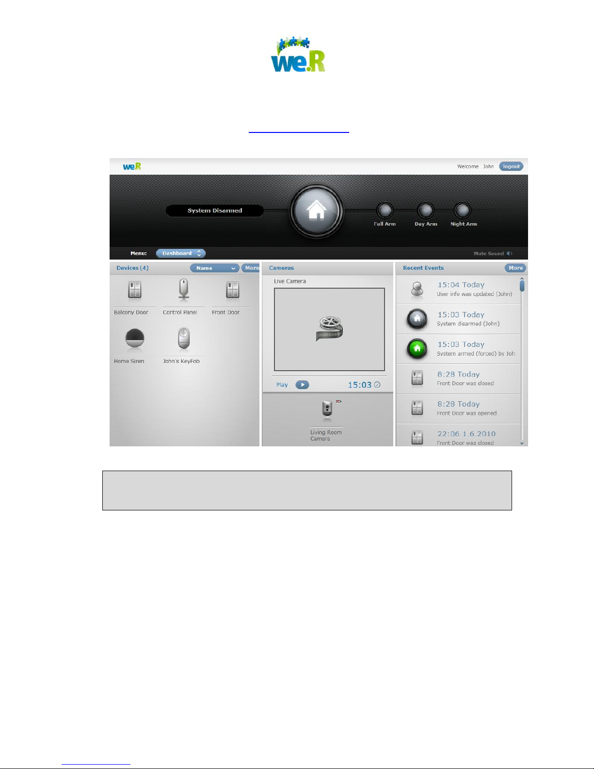
Log-in to the We.R system at www.wersystem.com to access the web-based user
interface to operate the system.
The system screens can be accessed through the Menu button, located on the left
side of the display.
Page 9 of 30
Page 10
4.2 Mobile Application
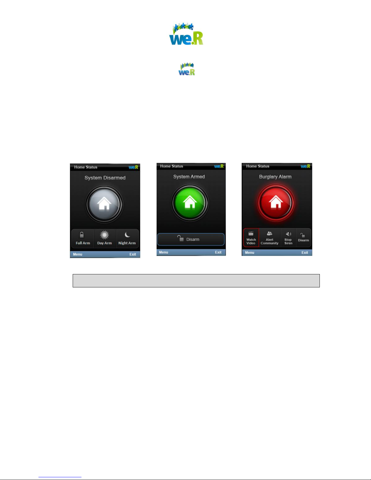
1. Open the We.R Mobile application .
2. If prompted to “Allow application We.R Mobile to use network and send or
receive data?”, then click “Yes”.
3. Enter your 4-digit PIN Code (from step #6 of “Registration” section), then click
“Login”.
4. If prompted to select an access point, then choose an Internet access point for
the We.R Mobile application to use. (3G connection is recommended.)
The system screens can be accessed through the Menu soft key.
Page 10 of 30
Page 11
5 Managing Devices
The kit you have purchased contains devices that were already added to the kit in our
factory, and so, they should not be added again to the system by you.
The “Adding a New Device” section below refers to new devices that were purchased
separately from the basic kit and the keyfob.
5.1 Web Application
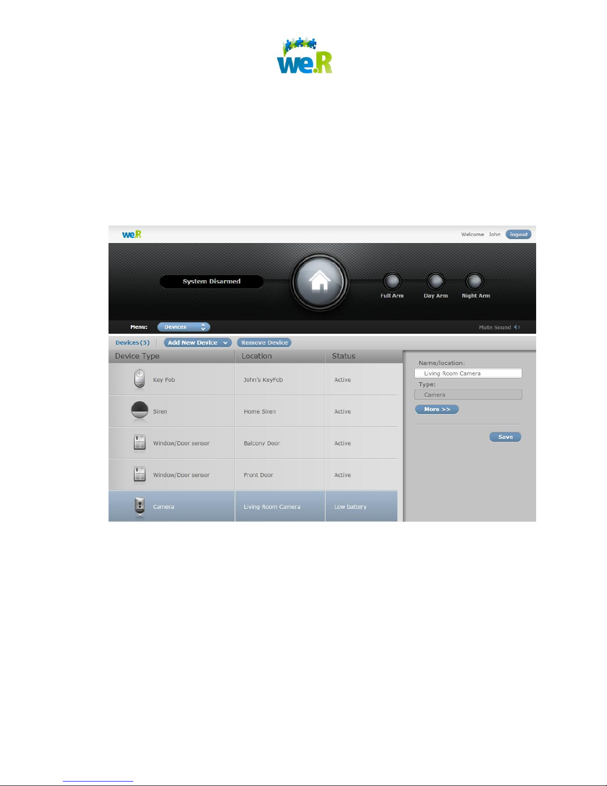
In the We.R System, go to the Menu and select “Devices”.
5.1.1 Adding a New Device
1. Click “Add New Device” and select the type of device that you wish to add.
2. Follow the instructions indicated on screen to add your device.
Page 11 of 30
Page 12
“Part arm” scenarios
Detection behavior
when armed
Detection behavior
when disarmed
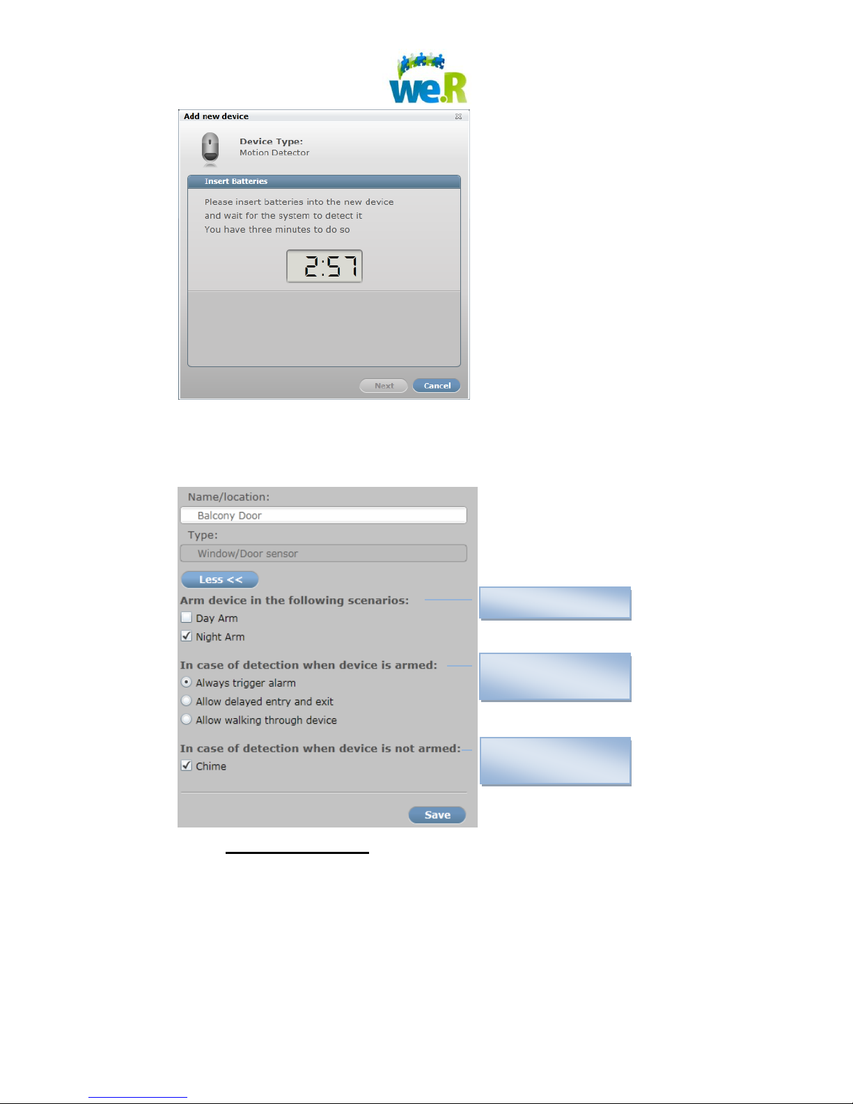
3. You can customize the following advanced properties for cameras, motion
detectors and window/door magnets:
a. Part arm scenarios:
Use this feature to make your everyday use of the we.R system
customized to your unique needs. Associate the device to a “part arm
scenario” (day arm or night arm) by checking the relevant box. Once
associated, the device will be armed every time this scenario is activated.
Page 12 of 30
Page 13

i. Day Arm – this scenario is mostly used for child care and safety,
allowing you to monitor and protect zones while at home. For
example, monitor your medicine cabinet by simply associating the
medicine cabinet door sensor with the “day arm” scenario and
activate this scenario while at home.
ii. Night Arm – use this scenario to protect and monitor zones on
nighttime while at home. For example, protect your front door,
balcony and living room by associating the relevant door sensors
and motion detectors with the “night arm” scenario and activate
this scenario at night while at home.
b. Detection behavior when armed:
i. Always trigger alarm
ii. Allow delayed entry and exit – the alarm will not be triggered in
case of detection by the device during a predefined number of
seconds. Delayed exit gives you time to leave through the
entry/exit door without triggering the alarm. Delayed entry gives
you time to disarm the system after you enter through the
entry/exit door.
iii. Allow walking through device – when leaving an armed house,
you can walk through this device during the delayed exit time
without triggering the alarm. When entering an armed house
through a “delayed entry” door, you can walk through this device
during the delayed entry time.
c. Detection behavior when disarmed:
i. Chime - monitor pre-designated areas while the security system is
not armed. Detection of device in "CHIME" mode will produce a
tone from the siren.
5.1.2 Removing Existing Device
1. Select the device in the devices list.
2. Click “Remove Device”
Page 13 of 30
Page 14

5.1.3 Editing Existing Device Details
1. Select the device on the device list.
2. In the “Device properties” window on the right, edit the relevant fields.
3. Click “Save”
5.1.4 Device Status
The system informs you regarding the current status of each installed device. The status
includes the following:
- Low battery. When this icon appears, replace the batteries in the device. This
warning enables a further 2 months of operation approximately. We advise to change
batteries immediately.
- Device was tampered.
- The connection between the device and the control unit was lost. This might happen
if the device is out of wireless range of the control unit, or alternatively, the batteries
have been removed.
The device status is presented in the Dashboard and on the Device screen.
5.2 Mobile Application
1. From the main Status screen of the We.R Mobile application, click "Menu", then
"Devices".
2. Click on the type of device that you would like to add. Click “New” and the follow
the instructions indicated on the phone to add your device to the We.R System.
Page 14 of 30
Page 15

TIP: When mounting all devices, ensure to attach the device to a
surface that is clean, dry, flat and smooth – for optimal performance of the
adhesive.
6 Mounting and Activating Devices
6.1 Mounting Camera
1. Please note that the Camera functions also as a Motion Detector.
2. Remove the mounting base & battery cover from the Camera and insert 3 AA
batteries. For the next 10 minutes, the red light in the Camera may glow
periodically as the device conducts a series of tests.
3. Replace the battery cover and mounting base onto the Camera.
4. Use the double-sided tape to mount the Camera (spherical lens pointed down)
on a wall, about 220 cm above the floor and at least 10 cm below the ceiling.
5. Place the Camera in a suitable location that does not face into sunlight or other
strong light sources.
6. For optimal surveillance, the Camera should be placed in a position where it will
capture images from the main point of entry.
7. Do not install the Camera in a location that is directly opposite a window.
8. For detaching the device from the wall (in case of battery replacement or any
other maintenance activity) push the white lock at the bottom of the device and
slide the device down.
6.2 Mounting Motion Detector
1. Remove battery cover from the Motion Detector and insert 2 AA batteries. For
the next 10 minutes, the red light in the Motion Detector may glow periodically as
the device conducts a series of tests.
2. Replace the mounting base onto the Motion Detector.
3. Use the double-sided tape to mount the Motion Detector (spherical lens pointed
down) on a wall, about 220 cm above the floor and at least 10 cm below the
ceiling.
Page 15 of 30
Page 16

4. Place the Motion Detector in a suitable location that does not face into sunlight or
other strong light sources.
5. For optimal surveillance, the Motion Detector should be placed in a position
where it will detect movement inside the home.
6. Do not install the Motion Detector in a location that is directly opposite a window.
7. For detaching the device from the wall (in case of battery replacement or any
other maintenance activity) push the white lock at the bottom of the device and
slide the device down.
Page 16 of 30
Page 17
6.3 Mounting Window / Door Sensors
1. Each window / door sensor has 2 components: a Magnetic Detector and a
smaller Magnet. Remove one Magnetic Detector from the box.
2. Open the Magnetic Detector, using a coin or a screw driver, insert one AA
battery and then close the device. (Repeat these steps for additional Magnetic
Detectors.)
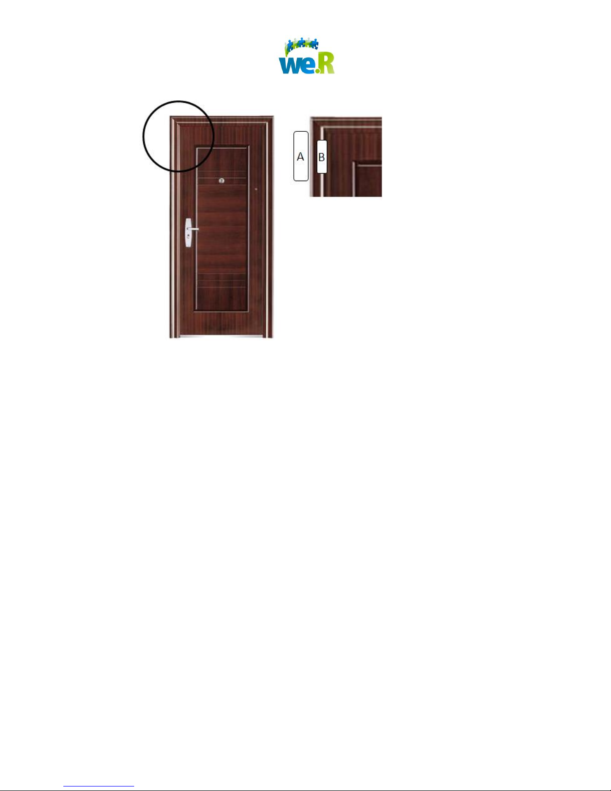
3. Use double-sided tape to mount the Magnetic Detector on the frame side of a
door or window opening. (See “A” in following diagram.)
4. Use double-sided tape to mount the Magnet on the surface of the door or window
itself, opposite the Magnetic Detector. (See “B” in following diagram.)
5. Both devices have a "•" mark on their fronts. Make sure that these "•" marks are
oriented toward each other and located at the same position and same height.
6. If required due to installation constraints, it is possible to mount the Magnetic
Detector on the surface of the door or window itself, and the Magnet on the
frame-side of a door or window opening.
7. A Green light indicates that the devices are coupled. A red light indicates that the
devices are out of range.
8. Recommendations:
Ideal mounting locations are high up and/or difficult locations for intruders to
reach.
Page 17 of 30
Page 18
9. For a quick test while magnet is fully installed:
Close the door / window – a Green light will glow, indicating correct
installation.
Open the door/ window – a red light will glow, indicating correct installation.
10. For detaching the Magnetic Detector from the surface of the door or window (in
case of battery replacement or any other maintenance activity) insert a coin or a
screw driver to hole, at the side of the device, and lift the Magnet cover up.
6.4 Mounting Indoor Siren
1. Remove the battery cover from the Indoor Siren and insert 4 AA batteries. (The
siren will give an audio indication that it is operational).
2. Replace the battery cover on the Indoor Siren.
3. Use double-sided tape to mount the Indoor Siren on a wall in a suitable location
that will allow the alarm to be heard and act as a deterrent to potential intruders.
4. For detaching the device from the wall (in case of battery replacement or any
other maintenance activity) push the white lock at the bottom of the device and
slide the device up.
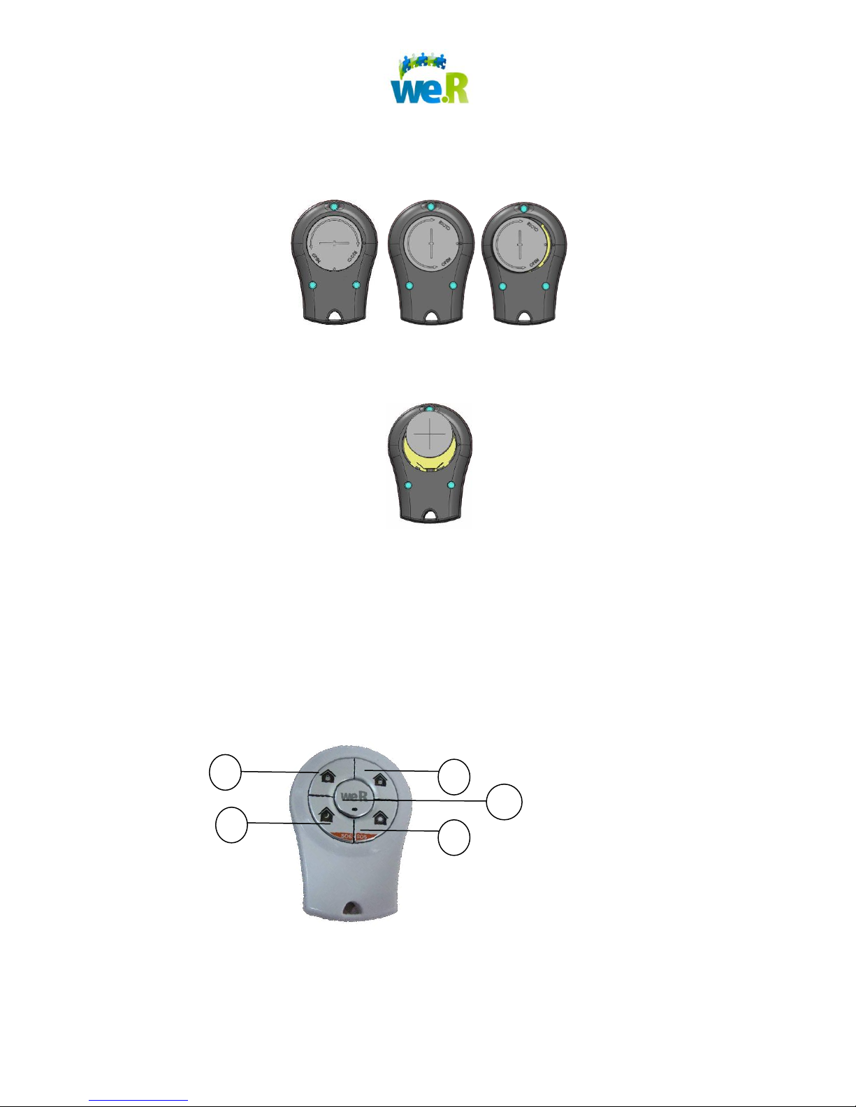
6.5 Activating the Key Fob
Page 18 of 30
Page 19
2 4 3 5 1
To insert the batteries:
1. Using a small coin, rotate the battery cover ¼ turn counter-clockwise,
until the two dots on the battery cover and the back of the device are
adjacent to one another, and remove the cover.
2. On the battery, note the surface marked +, indicating positive polarity.
3. With the surface marked + facing up, insert the battery into the battery
holder.
4. Replace the battery cover, and using a small coin, rotate the battery
cover clockwise until the two dots on the battery cover are in their
original positions.
All LEDs flash twice to indicate that the battery is connected.
6.6 Buttons and Indications
Page 19 of 30
Page 20
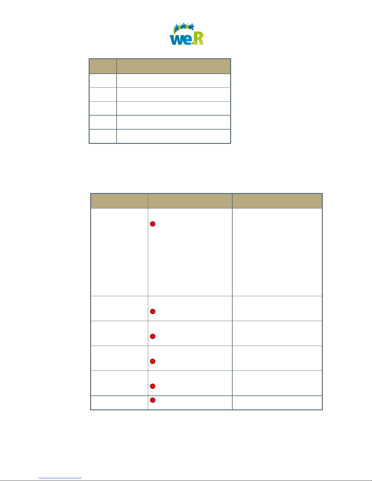
No.
Description
1
ARM button and LED
2
DISARM button
3
NIGHT-ARM button and LED
4
DAY-ARM button and LED
5
STATUS button
LED
Status
Description
Status
On
Red – short duration
Short Press on Status
Button – Status indicated in
Status LEDS
Long Press on Status
Button – enables triggers
for external devices
If LED flashes after
pressing one of the other
buttons – indication of low
battery status.
Disarm
On
Red – short duration
System disarmed
Night-Arm
On
Red – short duration
System partially armed
according to night scenario
Day Arm
On
Red – short duration
System partially armed
according to day scenario
Full Arm
On
Red – short duration
System Fully armed
All LEDs
Red - Flashes 5 times
Alarm in memory
Table 1: Buttons and LEDs
The table below summarizes the possible states of the LEDs.
Table 2: LED States
Page 20 of 30
Page 21
7 Managing Users
7.1 Web Application
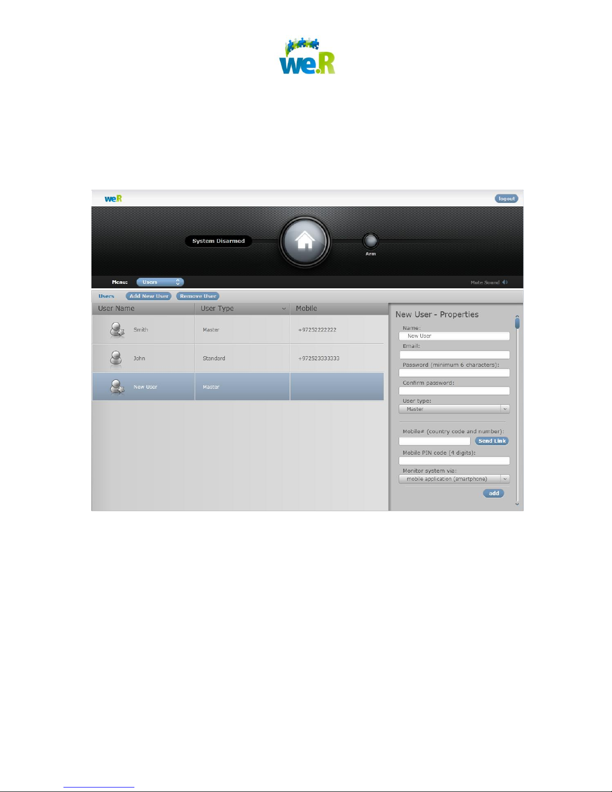
In the We.R System, go to the Menu and select “Users”.
7.1.1 Adding a New User
1. Click “Add New User”.
2. In the “New User properties” window on the right, enter information for all fields:
Username – must contain only alphanumeric characters
Password – a unique password, 6 characters or more
Profile –
o Master – Administrative privileges & full access to system
functions
o Standard – Full access to system functions
Page 21 of 30
Page 22

Mobile# – The user’s mobile phone (country code and number-digits only)
PIN Code – a unique 4-digit number to enter the We.R Mobile application
Send System Messages Via – For users of non-compatible phones,
select “SMS” to receive SMS messages only.
Email – the email account of the new user
3. Click the “add” button.
7.1.2 Removing Existing User
3. Select the user in the users list.
4. Click “Remove User”.
7.1.3 Editing Existing User Details
4. Select the user in the users list.
5. In the “New User properties” window on the right, edit the relevant fields.
6. Click “Save”.
7.2 Mobile Application
In the main Status screen of the We.R Mobile application, click "Menu", then "Users".
7.2.1 Adding a New User
1. Click "Menu" and select "New".
2. In the "New User" screen, enter the details of the new user:
Username – must only contain alphanumeric characters
Email – the email account of the new user
Password – a unique password, 6 characters or more
PIN – a unique 4-digit number to enter the We.R Mobile application
Phone No. – The new user’s mobile phone (country code and number-
digits only)
SMS user – For users of a non-compatible phones, to receive SMS
messages only.
User Type:
Page 22 of 30
Page 23

Master – Administrative privileges & full access to system
functions
Standard – Full access to system functions
3. Click "Add".
7.2.2 Removing Existing User
5. Select the user in the users list.
6. Click “Remove User”
Page 23 of 30
Page 24
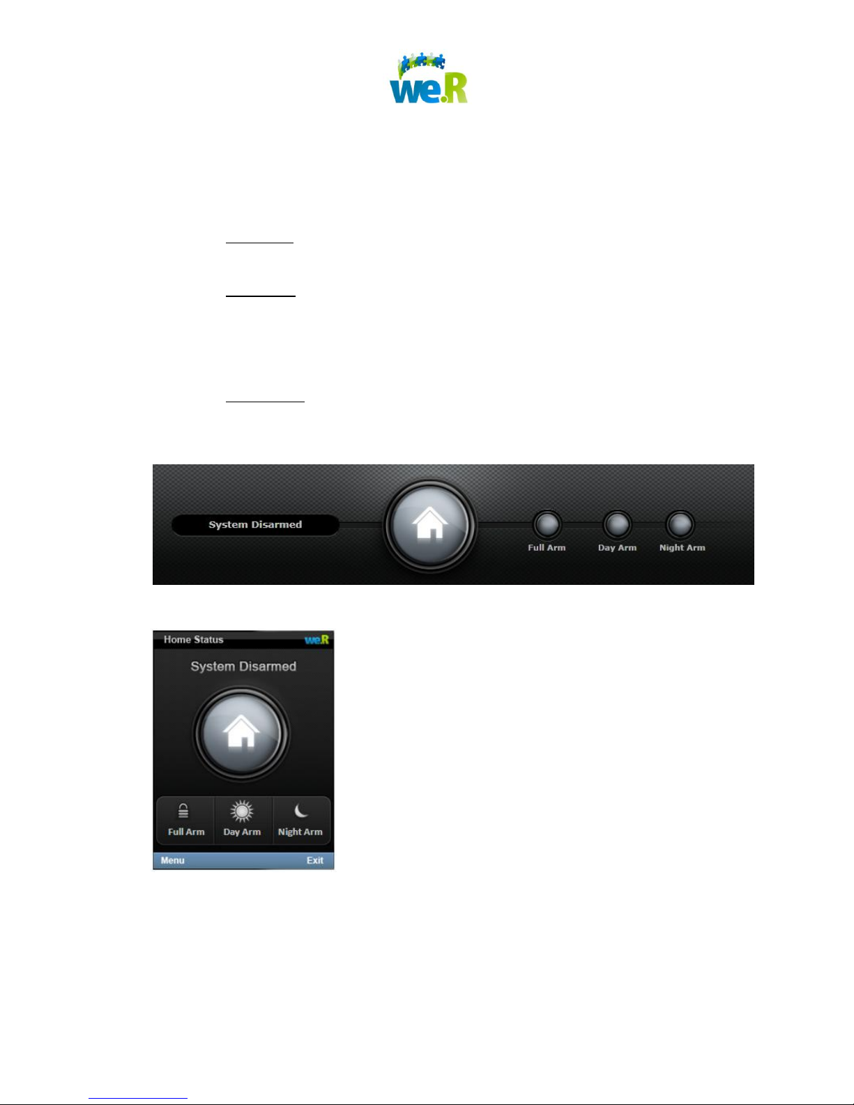
8 Arming and Disarming the System
8.1 Arm
1. When the system is disarmed, you can arm it by pressing one of the “Arm”
buttons:
a. “Full Arm” your system to protect all zones while away. This will arm all of
the devices in your premises and alarm will be triggered by any detection.
b. “Day Arm” your system while at home on daytime to protect and monitor
hazardous zones. This scenario is mostly used for child care and safety,
allowing you to monitor and protect zones like medicine cabinet,
basement etc.
c. “Night Arm” your system while at home on nighttime to protect your home
from intrusion. This scenario can arm for example only your front door,
back door and balcony.
Web application
Mobile application
2. Once the arming process is completed, the system status will be changed.
Page 24 of 30
Page 25
Force Arm
When arming the system, one or more of the devices may be tampered or open (in
case of monitored window/door). In this case you will be notified about these devices
and the system will allow you to perform a “force arm” – activate the arm anyway,
while the tampered and open devices will be bypassed.
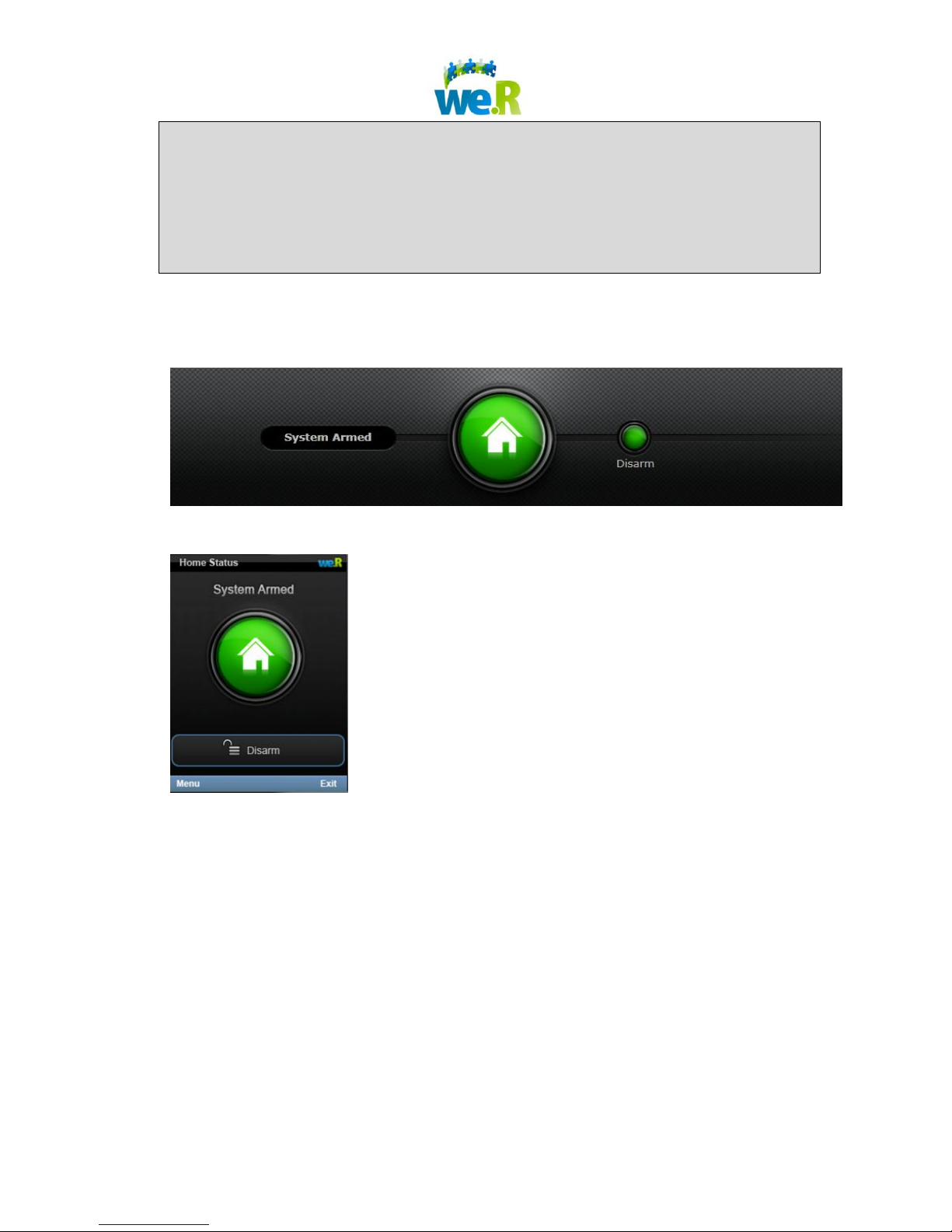
8.2 Disarm
1. When the system is armed, you can disarm it by pressing the “Disarm” button.
Web application
Mobile application
2. Once the disarming process is completed, the system status will be changed to
“Disarmed”.
Page 25 of 30
Page 26
9 Handling Alarms
9.1 Burglary Alarm
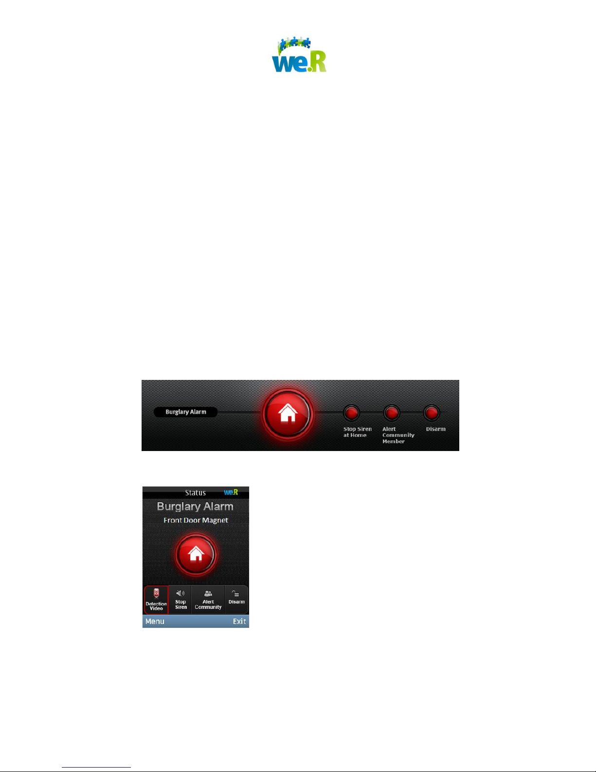
1. Once your system is armed, a burglary alarm will be triggered in the following
cases:
a. A monitored window/door was opened
b. A motion was detected by the motion detector or the camera
2. Once the alarm is triggered, you will receive an “Alarm” notification on the web
application (if you are logged in) and on your mobile phone through the We.R
Mobile Application.
3. Upon receipt of an “Alarm” notification, you have the following options:
a. Watch Video – View images from the cameras installed in your home
b. Detection Video – view images recorded automatically by the camera
that detected intrusion
c. Stop Siren – Alarm continues, but the siren is silenced
d. Disarm – Stop the alarm and disarm the system
Web application
Mobile application
Page 26 of 30
Page 27
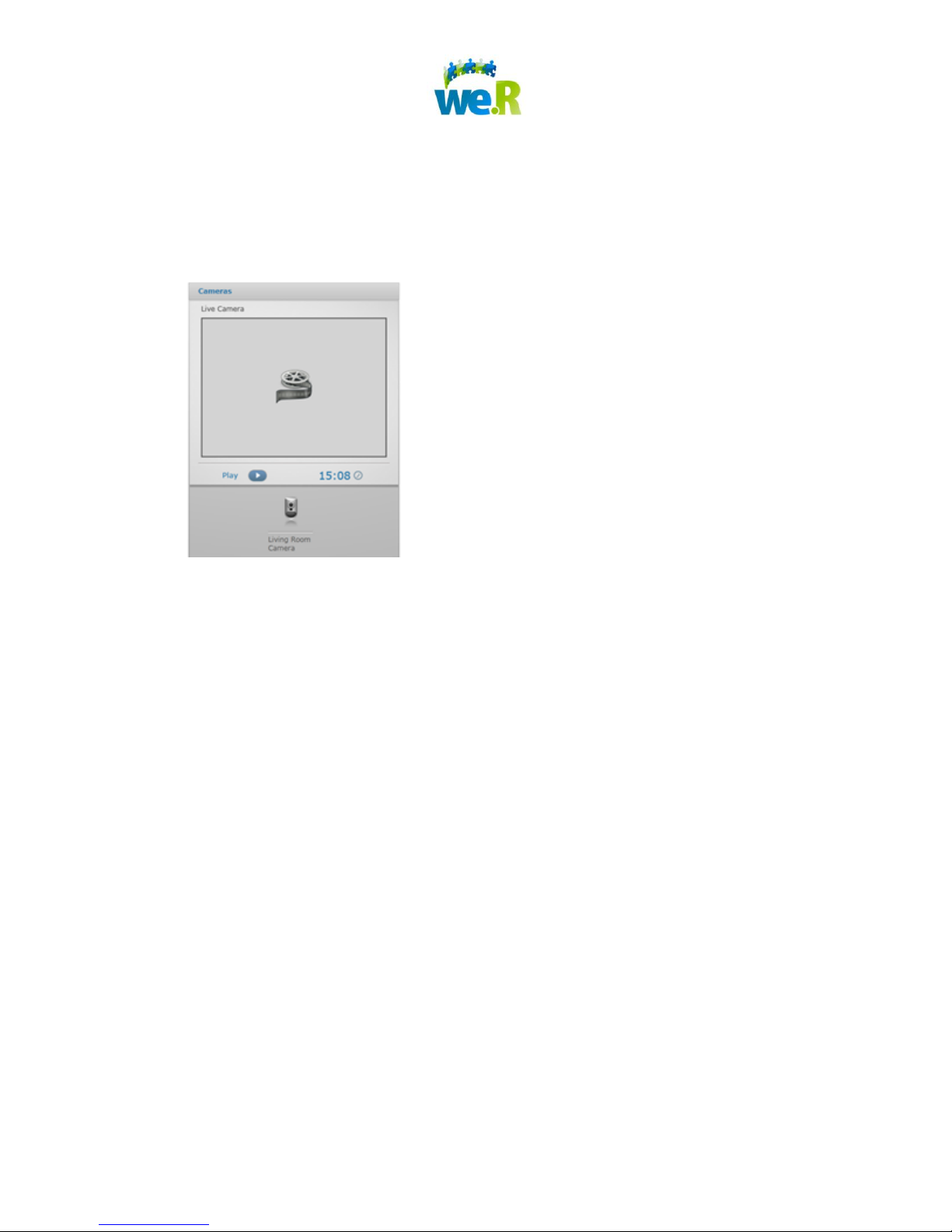
10 Watching Real-Time Videos
10.1 Web Application
1. On the main “Dashboard” screen, in the center “Camera/s” section, select your
Camera and push the “Play” button.
2. A 45 second video clip will run on your display.
10.2 Mobile Application
1. On the main Status screen of the We.R Mobile application, click "Menu", then
"Watch Video".
2. A 45 second video clip will run on your display.
Page 27 of 30
Page 28
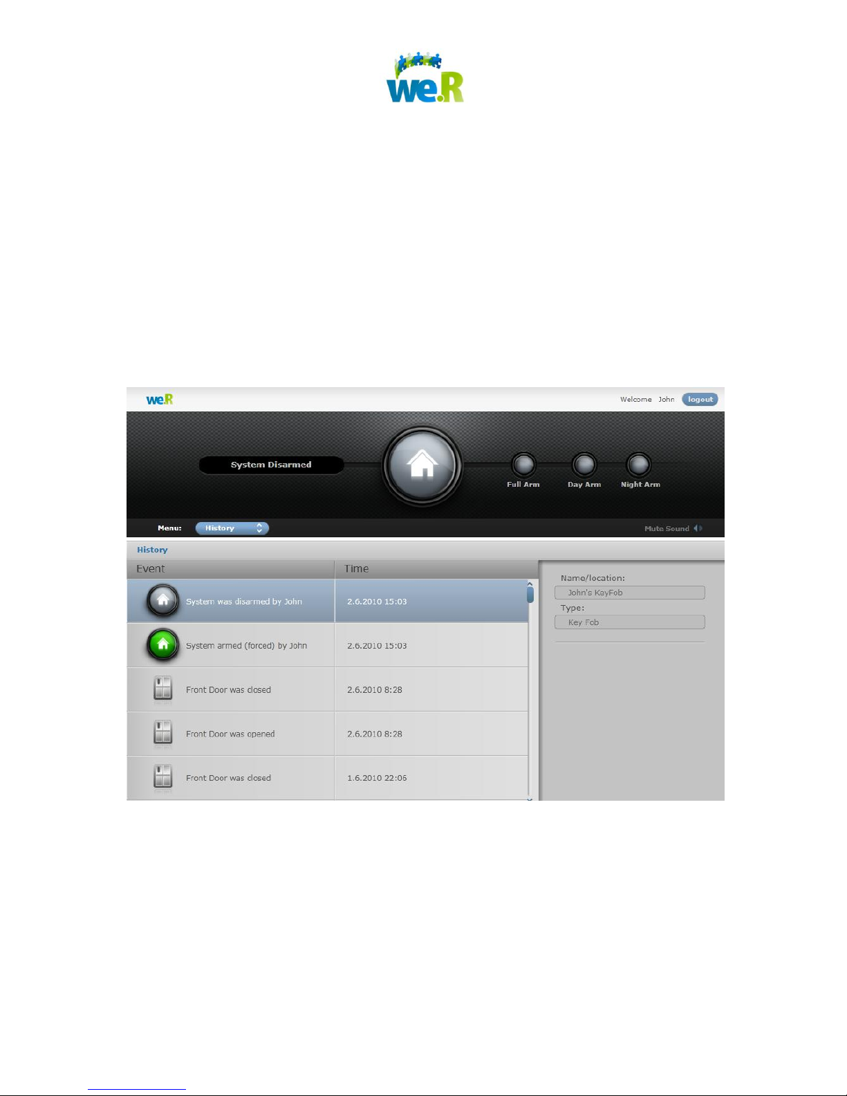
11 History – Reviewing Past Events
Review historical events of all types (security, safety, comfort)
Get additional event information by selecting from the events list and
reviewing the data in the “Event properties” window on the right.
Watch recorded videos by selecting relevant event and playing video in the
“Event properties” window on the right.
11.1 Web Application
In the We.R System, go to the Menu and select “Events”.
Page 28 of 30
Page 29
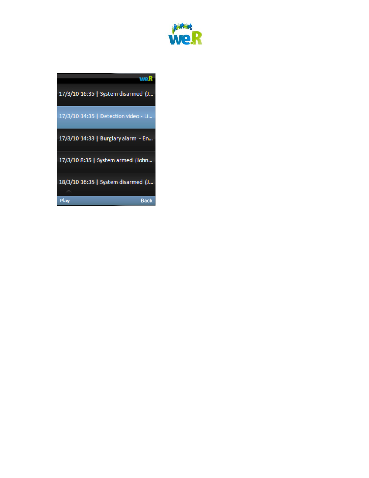
11.2 Mobile Application
On the main Status screen of the We.R Mobile application, click "Menu", then "History".
Page 29 of 30
Page 30

12 Troubleshooting
1. Trouble Activating a Device - If you have trouble activating a device within the
system, please ensure that the device is at least 2 meters away from the control
unit. If that does not help, then please perform these steps to restart the system:
a. Log-out of the We.R application running on a web browser and/or mobile
handset.
b. Unplug the Control Unit from its electrical source.
c. Open back of control unit and remove the battery.
d. Replace the battery and the battery cover and place the control unit on a flat
surface.
e. Plug the power cable back into the control unit. Ensure that the other end of
the power cable is plugged into an electrical socket.
f. Please wait for the light on the front of the control unit to glow green before
moving to the next step. (A green light indicates that the control unit has
completed the activation procedure, which can typically take about 2
minutes.)
g. Log-in to the We.R System and try again to activate the device.
h. If the light on the front of the control panel is still not Green, place the control
panel in a different room, to improve the Cellular network coverage.
2. If you have trouble adding one of the devices to the system, it might be due to
temporary radio interferences. Please repeat this step once again.
For Additional Assistance
Should you need more in depth information on features and services, please
contact the We.R Family & Home Management Kit Support Desk at support@wer-
mic.com.
Page 30 of 30
 Loading...