

Page 1

THIS APPLIANCE MUST BE COMMISSIONED BY A OFTEC REGISTERED ENGINEER
THE WARRANTY CARD MUST BE RETURNED TO ENSURE GUARANTEE VALIDITY
Ouzledale Foundry Co. Limited, Long Ing, Barnoldswick, Lancashire BB18 6BN
Tel: 01282 813235 Fax: 01282 816876 Email: [email protected] Website: http://www.esse.com
TH E A UT H E NT I C O RI G I NA L
1. BOIL ER BURNE R ECOFL AM PART NO
A. COMMON PARTS
Mounting Gasket 18.04.2001
Oil Pump Danfoss BFP 11R3 02.02.0002
Flexible Oil Line 740mm –
1
/4 BSP Braided 01.02.3002
Control Box Landis and GYR LOA 24 04.03.1013
Photocell Landis & GYR QRB1 04.03.3007
B. 0-106 BURNER
Nozzle 1.0 x 80ES 2021-258
Flame Tube BFB 01.153/002 01.01.1002
C. 0-80 BURNER
Nozzle 0.75 x 80ES 2021-256
Flame Tube BFB 01.002/002 01.01.1001
D. 0-60 BURNER
Nozzle 0.6 x 80ES 2021-254
Flame Tube BFB 01.104 01.01.1010
2. COOKE R BURNE R
Nozzle Danfoss 0.3 x 80ºH or Delavan 02.02.1150
0.3 80ºA
Flame Tube BFB 01.016/002 01.01.1020
Oil Pump Danfoss BFP 21 R3 02.02.0202
Flexible Oil Line 740mm –
1
/4 BSP Braided 01.02.3002
Control Box Landis & GYR LOA 24 04.03.1013
Photocell Landis & GYR QRB 1S 04.03.3011
3. THERM OSTATS ESSE PART NO
Boiler Thermostat Altecnic 540095 CENT 081 BO
Boiler Limit Stat Altecnic 541510 2040-640
Cooker Thermostat Anglo Nordic 1300608 2040-636
Cooker Limit Stat Altecnic 541887 CENT 082 BO
Neon Light 2040-645 BO
Control Knob Cooker Altecnic 2023-384 BO
Control Knob Boiler Altecnic 2040-200 BO
When ordering replacement parts, quote the cooker serial number and type.
REPLACEMENT PARTS
OIL FIRED COOKERS & BOILERS
INSTALLATION & COMMISSIONING INSTRUCTIONS
MODELS: OC, O-60, O-80 & O-106
09/07
Page 2

3
General Information Page 3
Technical Data Page 3
General Location Page 4
Electrical Supply Page 4
Oil Supply Page 4
Ventilation Page 4
Chimney/Flueing Arrangement Page 4
Water Systems & Wiring Diagrams Page 5
Installation Page 6
Door Hinge Adjustments Page 6
Commissioning Page 7
Comissioning the Programmer -
O-60, O-80 & O-106 models Page 10
Comissioning the Programmer -
OC Model Page 11
Fault Finding Chart Page 17
Commissioning Record Page 18
Service Record Page 19
Replacement Parts Page 20
The installation of the cooker, the chimney, hearth and walls adjacent to the cooker must conform to local
or national regulations currently in force. In the United Kingdom, the appropriate sections of the Building
Regulations must be conformed to.
O-106 29.3 (Output) 1.0 7.2 3.42 7.5 11.8 0-1
(100,000) 80°ES 105 8.5 10.8
O-80 23.44 (Output) 0.75 7.6 2.63 2 11.4 0-1
(80,000) 80°ES 110 3 10.4
O-60 17.54(Output) 0.6 7.0 1.97 2 11.1 0-1
(60,000) 80°ES 100 1 10.1
COOKER BURNER
OVERALL AIR SUPPLY & FUEL CONSUMPTION
TECHNICAL DATA
O-106, O -80, 10.55 (Input) 0.3 6.0 0.99 MIN + 6.0 0-1
O-60, OC 36,000 Btu/h 80° A or H 87 1 notch 4.5
O-106 170 4.41
O-80 130 3.62
O-60 100 2.96
MODEL AIR SUPPLY MIN TOTAL FUEL CONSUMP
CM
2
l/h*
MODEL OUTPUT/INPUT Nozzle Pressure†Fuel Air C0
2
Soot No
kW Size bar Consump. Setting %
(Btu/h) Type (p.s.i.) l/h* Approx
BOILER BURNER
GENERAL INFORMATION
CONTENTS
HEALTH & SAFETY AT WORK ACT 1974
(AND AMENDMENTS)
The installer has a responsibility under this Act, to provide
for the safety of person(s) carrying out the installation.
Attention is drawn to the following:-
1) The appliance is heavy and requires care in handling.
Lifting off the pallet and positioning may be carried out
using the Lifting Jack* available from ESSE dealers.
There may also be sharp edges on certain
components.
2) Fire cement is caustic and hands must be washed
thoroughly after use.
Although this appliance does not contain asbestos
products, it is possible that asbestos may be disturbed in
existing installations and every precaution must be taken.
*Patent applied for.
Important OC InstalLation INFOrmation:
OC ( coo king on ly) mode ls shou ld b e
installe d us ing the c ooker burner instr uctions
only. O C models do not have a boiler and
ther efo re al l boi ler i nst uct ion s are n ot
required and can be ignored.
* Constant Running † This pressure must not be exceeded
Page 3

54
Floor
The cooker weighs 350kg (786lbs) approx. The floor must be solid and level.
Elect rica l Supply
An electrical supply from an adjacent fused spur is required. 230/250 volts AC50Hz. Fuse rating
3 amps. One cable is supplied, which is live into programmer (black cable), see Wiring Diagrams.
A 3 channel pre-wired programmer is incorporated into the
cooker.
Oil Supp ly
The cooker is supplied for use only on Commercial Kerosene. 28 sec to BS 2869: 1983 Class C2.
Incoming oil supply should not be less than 10mm copper. The L.H. side panel can be removed for
access to the fitting (Fig 3). A tiger loop system may be used if required.
Ventil ation
A supply of air is necessary for correct combustion via a purpose made air brick or grid. The minimum
effective air requirement for the appliance is as specified in the Technical Data Section (Page 3).
It should be noted that the cooker will emit a certain amount of convected heat and ventilation
arrangements should allow for this.
Where an extract fan is provided to vent the room of cooking smells, steam, etc, arrangements must be
made to avoid any possibility of reversing the flow in the chimney. Arrangements for ventilation must
always comply with any local by-laws or Code of Practice relevant to the installation.
Chimn ey / Flueing Arran geme nt
The flue box is suitable for 125mm (5”) cast iron smoke pipe to BS 41. Either top or rear connection is
achieved by fitting the blanking plate supplied. The flue should run into a chimney of not less than 125mm
(5”) internal diameter.
A conventional chimney should not be less than 125mm (5”) internal diameter. A continuous flexible
metallic liner (min 125mm (5”) diameter) suitable for oil, must be used to line an existing chimney.
Alternatively a clay liner to BS 1181 may be used.
A proprietary, fabricated chimney should conform to B S 4343. The minimum flue height should be 4.75m
(15’). In all cases the chimney should conform to relevant Building Regulations.
Note: If on commissioning the appliance a minimum flue draught of 1.02mm (0.04”) w.g. cannot be
achieved (due to local topographic conditions) a fan flue system may be required.
Water Sys tems & Wiring Dia grams
As the heat conducted from the oven to the hot water system is negligible, either a fully pumped system or
a pumped central heating and gravity hot water system may be used in accordance with current regulations.
Power Flu sh Water Sy stems
If the century is to be fitted onto an existing water system then it must be power flushed prior to the
commissioning of the unit and inhibitor re-added. Failure to carry out this operation will seriously affect
boiler performance and negate any warranty claim.
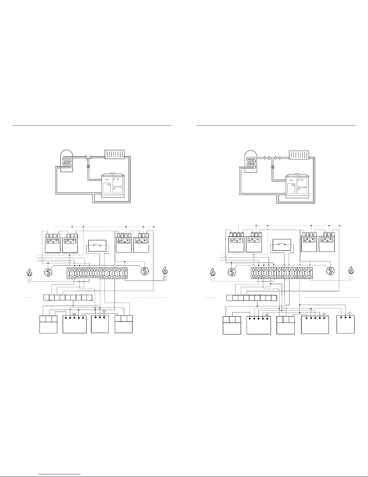
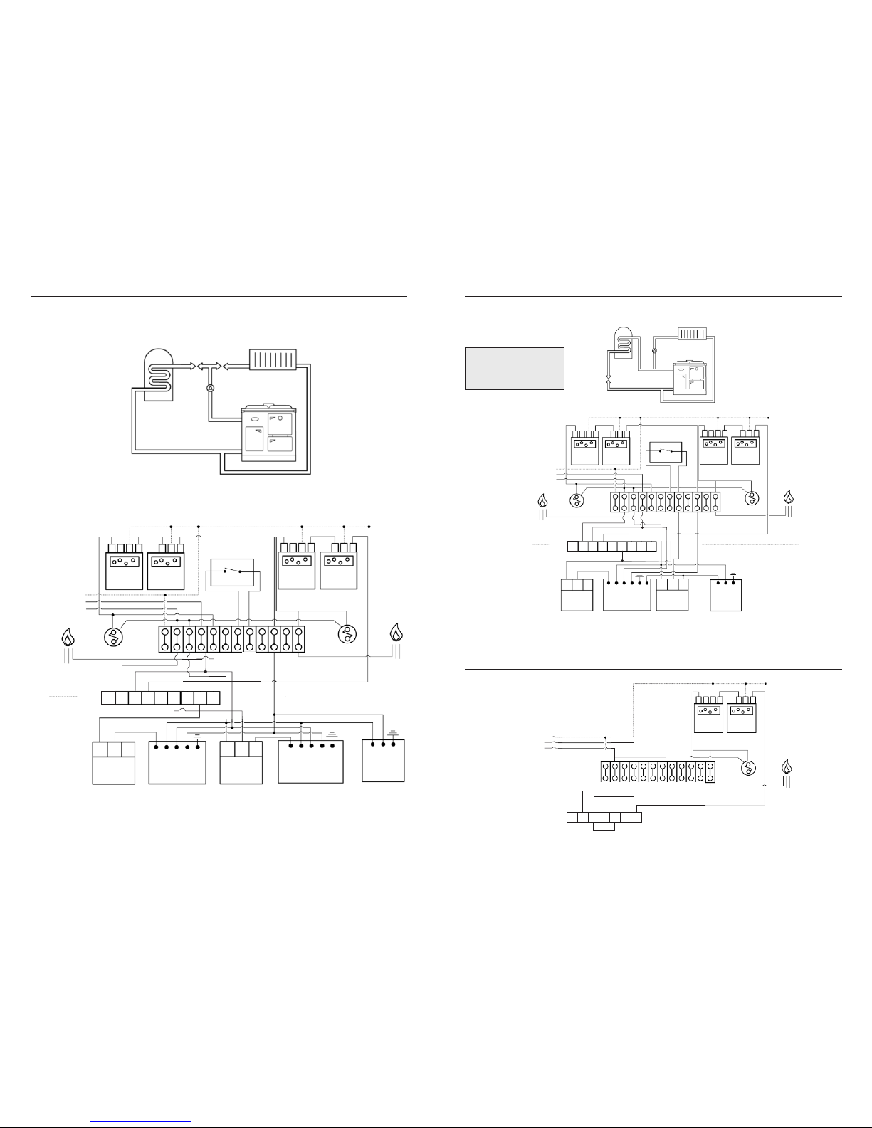
The cooker is factory wired to suit heating and hot water at the same time, using only 2 channels of the
programmer (figs 4, 5 & 6). If hot water is required to be programmed separately from the central heating, the
3rd channel of the programmer is used (fig 5a). The relevant stickers suppliedshouldbe fitted to the programmer.
Commission the programmer as described in figs 3a & 3b. Typical systemsare shown in Figs. 4, 5, 5A, 6 & 6A.
The water system and the electrical wiring system used must be in accordance with current regulations.
The foll owin g genera l point s should be no ted:
1) An indirect system is essential in all cases. Cylinder capacity should not be less than 136 litres (30 gallons).
2) The tappings are 1”BSP. Connection may be made through the left-hand side panel. The flow tapping
must be 28mm (1.09”) pipe and any reduction made on a rising section of the piping.
3) Water circuit layout must follow establishedheating practice. The cooker must be level when fitted and
the primary flow and return pipes must rise from the boiler. A drain cock must be fitted at the lowest
point of the circuit and a permanent vent to atmosphere provided at the highest point.
4) The cylinder and pipe work must be insulated to avoid heat losses.
5) The system pressure must not exceed 2 Bar, and be fitted with a pressure release valve.
6) The maximum water temperature is 90°C.
7) Water capacity of boiler is 14.5litres (3.2 gals).
Gener al Loca tion
A 7mm air gap should be left either side of the black enamel top from combustable surfaces.
The location of the cooker must have:-
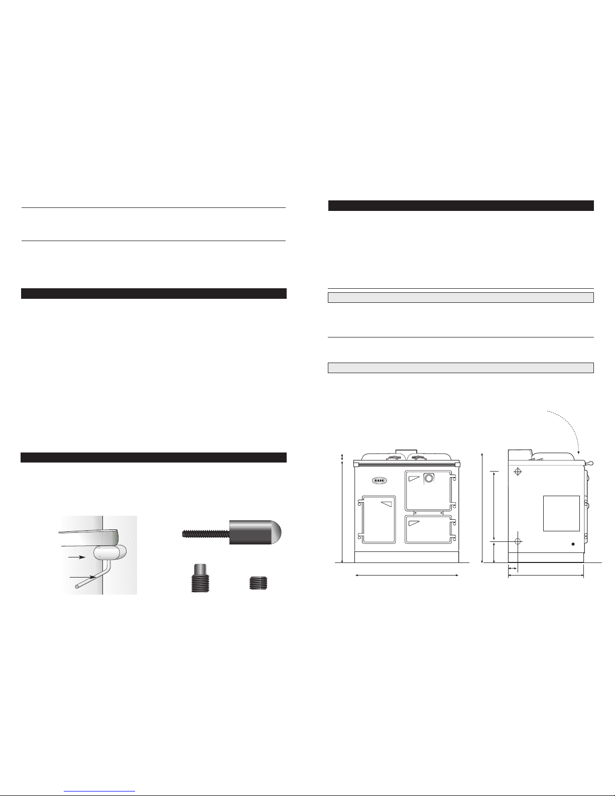
1) Sufficient room for the installation. (Fig. 1)
2) A satisfactory flue.
3) Adequate air supply.
5) Access for oil connection and fire valve.
4) Solid floor or base capable of supporting the
total weight.
The points above are covered in more detail below.
Important: For the burner to function correctly, a steady chimney draught not exceeding 2.5mm (0.10”)
w.g. and not less than 1.02mm (0.04”) w.g. is required. The draught should be assessed with a reliable
manometer after running both burners at a high control setting for at least thirty minutes. Down draught
cannot be tolerated and arrangements must be made to overcome this condition where it occurs. Flue
pipe connection should be made with good quality fire cement to make sure of an airtight seal between
the flue box and the flue pipe. Any soot door, register plate etc, must also be sealed to form an airtight
joint. Three schematic diagrams of installation methods are shown in Fig. 4, 5, 5a, 6 and 6a but
modifications may be made to suit site requirements. In all cases, however, the important principle that
no air must enter the chimney except through the inlets provided on the cooker, must be adhered to.
The preferred option is to connect the flue liner direct to the flue pipe to ensure good seals.
The foll owin g genera l point s should be no ted:
1) The fabric of the chimney must be sound and the internal surface smooth and free from obstructions.
Any air leaks and bad joints must be rectified.
2) The chimney should be terminated in such a manner to prevent ingress of rain.
3) The chimney must serve the cooker alone and not be shared with any other appliance.
4) External flues of asbestos or cast iron pipe must not be used. Excessive exposure will result in heat
loss and poor performance.
5) Provisionshouldbe madefor means of sweeping.
6) The maximum water temperature is 90°C.
7) Water capacity of boiler is 14.5litres (3.2 gals).
Page 4
6 7
”
”
”
”
”
”
”
”
”
”
”
COMMISSIONING
i) Remove both upper & lower locking grub screws from hinges using the 3/16” allan key provided.
ii) Using the same allan key, adjust either or both eccentric pins in each door hinge to level the door.
iii) Once the door is level, lock the eccentric pins in place using the locking grub screws.
Door
SIZES ARE APPROXIMATE ONLY. VARIATIONS MAY OCCUR IN MANUFACTURE.
3/16” Allan Key
Door Hinge
Eccentric
pin
Locking
grub screw
INSTALLATION
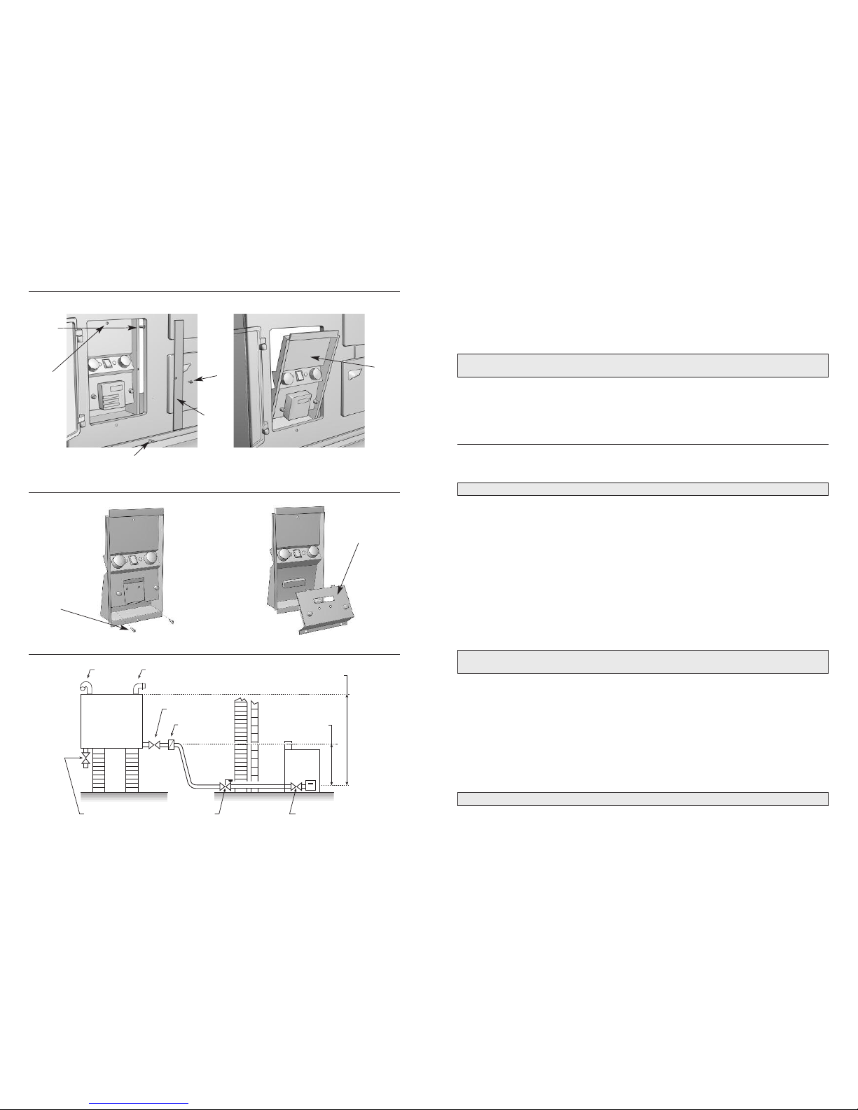
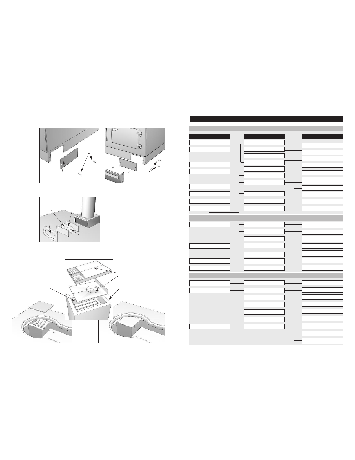
The cooker is supplied with the air intake at the front. If required the air intake can be taken from the rear
as follows:- (Fig. 7)
i) Remove the kicker plate securing screws.
ii) Remove the blanking plate located at the rear right-hand corner of the base. Fix the blanking plate over
the front primary air intake at the front right hand corner of the base.
iii) Replace the kicker plate.
Move the cooker into position. Connect water flow and return pipes. Remove left-hand panel and connect
oil supply. Fit electrical cables to the chosen system. Replace left-hand side panel. Fit the flue box. Make
the flue connection.
Fit the flue box sealing plate and gasket. Fit the flue box door (Fig. 8)
Fit the towel rail using the towel rail brackets supplied.
The baffle arrangement above the boiler heat exchanger need not be disturbed on installation.
If however, they have been removed for any reason, then they must only be replaced as shown in Fig. 9.
DOOR HINGE ADJUSTMENTS
Bypas s
A bypass should be fitted. Where the water system can allow the boiler and pump to operate on bypass
only, the bypass must be placed at least 1.5m (5’3”) away from the boiler.
Inhib itor
Attention is drawn to the current issue of B S5449 and BS 7593 on the use of inhibitors in central heating
systems. If an inhibitor is to be used, contact an inhibitor manufacturer for their recommendations as to
the best product to use.
The water system and the electrical wiring system used must be in accordance with current regulations.
This appliance is fitted with two oil pressure jet type burners and must be commissioned by an
experienced pressure jet engineer (OFTEC) with the necessary equipment available for setting up the
burner and checking that combustion characteristics and chimney draught comply with those detailed in
the text.
Failure to comply will lead to incorrect operation, nuisance shutdown, equipment failure or damage to
appliance. GUARANTEE will be invalidated if the appliance is not correctly commissioned.
Proce dure
Important: Ens ure the mains supply is isolated and that both thermo stats are at t he off position.
Remove control panel.
Check the oil and water connections for soundness.
Boile r Burne r ( Left Ha nd Burne r)
Connect combined air bleed manifold and pressure gauge to pump.
Re-establish the electricity supply to the cooker.
Warning: The power is now live. Extreme caut ion must be ex ercised .
Check that any ancillary controls e.g. room thermostat, programmer etc., are in an ON position.
Turn boiler thermostat to 80°C position. Burner should start ignition sequence.
(When the burner motor starts on a one pipe system it may be necessary to temporarily open the air bleed
screw on test manifold).
Page 5
9
Once burner is firing check and if necessary adjust oil pressure. (see Technical Data).
Carry out combustion checks by inserting probe into sampling point provided at the flue box behind the
cast iron flue hood access door. (Fig. 8) The air setting is pre-set.
Check the smoke number and if necessary increase the air setting progressively until a number between
0 and 1 is achieved.
Note: From cold an d particularl y on a new installation, there will b e a condensa tion o f the flue gases
and this may a ffect the paper
Allow boiler to heat up for a further 10 minutes then check smoke number, adjusting the air if necessary
(see Technical Data). Monitor the flue draught at the same point and check that a steady updraught is obtained.
Turn boiler thermostat to ‘O’. Isolate mains supply and remove the pressure gauge.
Cooke r Burne r ( Righ t Hand Burn er)
Connect combined air bleed manifold and pressure gauge to pump.
Re-establish electricity supply to the cooker.
Warning: The cooke r power is n ow l ive. Extreme caution must be ex ercised.
Check that any ancillary controls e.g. programmer etc are in an ON position.
Turn cooker thermostat to 250°C position. Burner should start ignition sequence.
(When the burner motor starts on a one pipe system it may be necessary to temporarily open the air bleed
screen on test manifold).
Once burner is firing check and if necessary adjust oil pressure (see Technical Data).
Carry out combustion checks by inserting probe into sampling point provided at the flue box. (Fig. 8)
The air setting is pre-set at minimum.
Check the smoke number and if necessary increase the air setting progressively until a number between
0 and 1 is achieved.
Note: From cold an d particularl y on a new installation, there will b e a condensa tion o f the flue gases
and this may a ffect the paper.
Allow cooker to heat for a further 10 minutes then check smoke number, adjusting the air setting if
necessary (see Technical Data). Monitor the draught at the same point and check that a steady updraught
is obtained.
Turn cooker thermostat to OFF. Isolate mains supply, remove pressure gauge and replace the control panel.
To complete the commissioning process, you must fill in both of the following:
a) Commissioning Record - at the back of this booklet on p18
b) Commissioning Confirmation Form - a separate leaflet supplied with this cooker.
Important: Failure to complete thes e do cuments will inva lidate the warrant y of th is p roduct.
8
Infil plate
D
oor pin
C
ontrol
panel
Upper
c
ontrol
panel
s
ecuring
screw
Wiring panel securing
screws
WIRING PANEL
Lower control panel securing screw
AllAn
Screw
Oil Inst allation Sch emat ic Diagr am - Fig.3
vent
filler
drain valve
remote operated
fire valve
shut-off valve
oil tank
isolating valve
filter
cooker
10ft (3m) max head of oil
18” (475mm)
min head of oil
Remov ing the Wi ring Pan el - Fig.2b
Remov ing the Co ntrol Pan el - Fig.2 a
Page 6
1110
All ChannelPlus XL controls are fitted with battery reserve which maintains programmed times in the event
of a mains power failure.
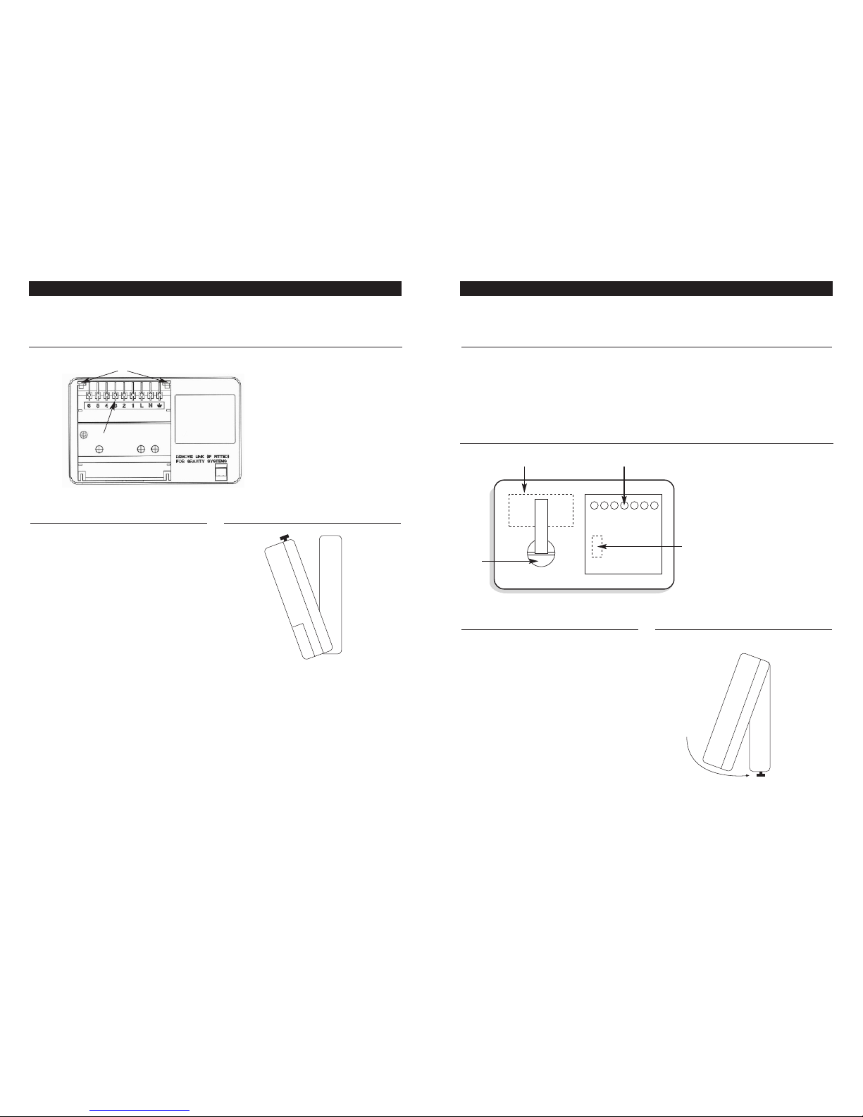
Rear Vie w of ChannelPlu s XL Programmer - Fig .3a
1. Retaining Screws
2. Connector Blades
3. Production Date Label
4. Positioning Lugs
5. Ratings Label
Fitti ng the Pro gramm er
If surface wiring has been used, remove the
knockout/insert from the bottom of the programmer
to accommodate it.
Loosen the two ‘captive’ retaining screws on the
bottom of the backplate. Now fit the programmer
to the backplate, ensure the lugs on the backplate
engage with the slots on the programmer.
Swing the bottom of the programmer into position
ensuring that the connection pins on the back of
the unit locate into the terminal slo ts in the
backplate.
Tighten the two ‘captive’ retaining screws to fix the
unit securely. Then switch on the mains supply.
End View of Ce ntau rPlus Pr ogrammer
COMMISSIONING THE PROGRAMMER - O-60, O-80 & O-106 Models COMMISSIONING THE PROGRAMMER - OC Model
All CentaurPlus controls are fitted with battery reserve which maintains programmed times in the event of
a mains power failure.
Batte ry Rese rve
The battery must be commissioned prior to fitting the control to the backplate. This is achieved by the
means of a COMMISSIONING STRIP situated on the back of the unit. Pull out the battery commissioning
strip at the back of the programmer and re-insert the battery, the reserve is now activated.
When the programmer is running on battery reserve the clock display will disappear. This is to prolong the
life of the battery.
Rear Vie w of CentaurPlu s Programmer - Fig .3b
1. Ratings Label
2. Battery
3. Connector Pins
4. Production Date Label
5
1
4
3
Remov ing/ Fitti ng the Pro gramm er
Loosen the two ‘captive’ retaining screws on the
top of the unit. Now fit the programmer to the
backplate, line the lugs on the programmer with
the flanges on the backplate.
Swing the top of the programmer into position
ensuring that the connection blades on the back
of the unit locate into the terminal slots in the
backplate.
Tighten the two ‘captive’ retaining screws to fix the
unit securely, then switch on the mains supply.
End View of Ch anne lPlus XL Pr ogrammer
1 3
4
2
2
Page 7
1312
H
oneywell ‘Y’ plan - fully pumped hot water and heating
Boiler
stat
Boiler
burner
Cooker
programmer
Cylinder stat
L641A or equivalent
V40 73A Mid position
Valve or equivalent
Room stat
T6306B or equivalent
Pump (2.5 amp max)
Cooker
burner
Boiler
status
neon
Cooker
status
neon
Boiler
Limit stat
Hot water
C
1EC2 EC2
1EC2 EC2
1
2
12
5
4
EN
NE
N EL
3
3
21LNE
12 34 56 7 8 910 11 12
GREY
BLUE
GREEN/YEL
ORANGE
WHITE
Internal wiring
External wiring
Cooker
Limit stat
Mains E
supply L
(3 AMP N
fuse)
Cooker
stat
Heating/
Hot water
V
4073A
6
HORSTMANN
H37XL
Boiler
stat
Boiler
burner
Cooker
programmer
Cylinder stat
L641A or equivalent
DHWS Cylinder primary
motorised valve
-28mm V4043H
or equivalent
Heating circuit
motorised valve
V4043H
or equivalent
Room stat
T6306B
or equivalent
Cooker
burner
Boiler
status
neon
Cooker
status
neon
Boiler
Limit stat
Hot water
C
1EC2
E
C21
E
C2
E
C2
1
231
EN
NE
LEN
2
12345678910 11 12
BROWN
BLUE
GREY
ORANGE
GREEN/YEL
Internal wiring
External wiring
Cooker
Limit stat
Mains E
supply L
(3 AMP N
fuse)
Cooker
stat
Heating/
Hot water
H
oneywell ‘S’ plan - fully pumped hot water and heating
BROWN
BLUE
GREY
ORANGE
GREEN/YEL
Pump (2.5amp max)
V4043H V4043H
5
4
321
L
NE6
HORSTMANN
H37XL
Honey well ‘Y ’ Plan - Fig.4 Honey well ‘S ’ Plan with he atin g a nd hot wat er timed to geth er - Fig.5
Page 8
1514
Honeywell ‘C’ plan - gravity hot water and pumped heating
V
4043H
B
oiler
stat
Boiler
b
urner
Cooker
programmer
DHWS Cylinder
stat L641A
or equivalent
DHWSCylinder
primarymotorised
valve-28mm V4043H
or equivalent
Pump
(2.5amp max)
Room stat
T6306B
or equivalent
Cooker
burner
Boiler
status
neon
Cooker
status
neon
B
oiler
Limit stat
Hot water
1EC2
E
C2
1EC2 EC2
12
EN
NE
NEL
321C
12345678910 11 12
GREEN/YEL
WHITE
Internal wiring
External wiring
C
ooker
Limit stat
Mains E
supply L
(3 AMP N
fuse)
C
ooker
stat
Heating/
Hot water
BROWN
BLUE
GREY
ORANGE
Honey well ‘C ’ Plan - Fig.6
54321LNE6
HORSTMANN
H37XL
Cooker
programmer
Cooker
status
neon
1
E
C2
E
C
2
NE
123 4 56 78 9 10 11 12
Cooker
Limit stat
Mains E
supply L
(3 AMP N
fuse)
Cooker
stat
4321LNE
HORSTMANN
C17
Model OC (C OOKER O NLY) - Fi g.6a
Boiler
stat
Boiler
burner
Cooker
programmer
Cylinder stat
L641A or equivalent
DHWS Cylinder primary
motorised valve
-28mm V4043H
or equivalent
Heating circuit
motorised valve
V4043H
or equivalent
Room stat
T6306B
or equivalent
Cooker
burner
Boiler
status
neon
Cooker
status
neon
Boiler
Limit stat
Hot water
C
1EC2 EC21EC2 EC2
1
2
3
1
EN
NE
LEN
2
12345678910 11 12
BROWN
BLUE
GREY
ORANGE
GREEN/YEL
Internal wiring
External wiring
Cooker
Limit stat
Mains E
supply L
(3 AMP N
fuse)
Cooker
stat
Heating/
Hot water
H
oneywell ‘S’ plan - fully pumped hot water and heating
BROWN
BLUE
GREY
ORANGE
GREEN/YEL
Pump (2.5amp max)
V4043H V4043H
Honey well ‘S ’ Plan with he atin g a nd hot wat er timed se pera tely - Fig. 5a
5
4
321
L
NE6
HORSTMANN
H37XL
Cooker
burner
Note: For a gravity primary and
p
umped heating system without a
zone valve, cylinder thermostat or
room thermostat, link terminals 7 &
1
0 and wire pump live to terminal 8
Page 9
17
BURNER FAILS TO START
BURNER FAILS TO START AFTER NORMAL OPERATION
P
OSSIBLE CAUSES
S
ITUATION
R
EMEDIES
F
lame instability
M
otor Runs
C
heck nozzles to burnerhead dimension
a
nd electrode position
Incorrect head settings
Burner pre-purges
Check oil pressure
Low oil pressure
A
djust air damper
Excess air
Flame occurs
Check that photo cellis clean and unobstructed
Photo cell not seeinglight
Burner locks out
Confirm with photo cell
Photo cell failed
C
onfirm with new control (NB. Itis advisableto
c
hange the photo cellif also changing control)
Control faulty
Motor runs
Check that photo cellis not
seeing ambient light
False light
B
urner pre-purges
Check that H.T. leads are sound and are not
arcing other than atelectrode gap
No spark
No flame occurs
C
heck oil supply toburner-
c
heck that pump isnot airlocked
No oilBurner locks out Check operation of magneticvalve.
Check or replace fuseif necessary.
Check reason for failure
Adjust thermostat
Reset overheat device, findreason
for it’s operation andrectify
Check by replacement
Fuse has blown
Appliance thermostat has not reset
Appliance overheat device has operated
Control relay or photocell defective
Burner fails to start
Lamp not lit
Oil not being delivered
Excess flue draught ispreventing
flame establishment
No sparkBurner runs tolockout
Motor runs
Check that oil tank,oil lines, fire valve, pump
and nozzle are allin good order
Rectify condition
Check ignition transfor mer.Check electrodegap
and porcelains
DELAYED IGNITION, BURNER STARTS VIOLENTLY
Recomission burner
Replace nozzle
Check and recomission
Check and rectif y
Check and tighten
Check and replace
Check the electrode adjustment,
see diagram
Check electrodes for damage
Check H.T. leads for damage and disconnection
Excessive draught
Nozzle partly blocked
Oil pressure too low
Flue blocked or damaged
Fan slipping on shaft
Pump coupling loose orworn
Delayed ignition
Burner pulsates on start-up
only with hot flues
Burner pulsates - on star t up
Burner starts violently
BOILER/COOKER FAULT FINDING CHART
16
Front of cooker
Baffle
Arrangement
Blanking plate
Flue box door
Boiler burner
combustion
sampling point
Cooker burner
combustion sampling
point
Flue box
sealing plate
and gaskets
Blanking plate
s
ecuring screws
K
icker strip securing
screws
Efficiency baffles
0-60 & 0-80 only
(not shown)
Blank ing Pla te - F ig.7
Sampl ing Poin ts - F ig.8
Baffl e Arrangemen t - F ig.9
Page 10

19
Engineers Name Date
A
ddress
Tel No. Fax No.
O
FTEC/Reg No.
Engineers Name Date
Address
Tel No. Fax No.
OFTEC/Reg No.
Engineers Name Date
Address
Tel No. Fax No.
OFTEC/Reg No.
Engineers Name Date
Address
Tel No. Fax No.
OFTEC/Reg No.
Engineers Name Date
Address
Tel No. Fax No.
O
FTEC/Reg No.
18
Engineers Name Date
Address
Tel No. Fax No.
OFTEC/Reg No.
Engineers Name Date
Address
Tel No. Fax No.
OFTEC/Reg No.
Engineers Name Date
Address
Tel No. Fax No.
OFTEC/Reg No.
COMMISSIONING RECORD
SERVICE RECORD
 Loading...