

Page 1

Esse Engineering Limited, Long Ing, Barnoldswick, Lancas hire BB18 6BN
Tel: 01282 813235 Fax: 01282 816876 e-mail: enquiries@es se.com
Website: http://www.esse.com On-line Store: http://www.e sseparts.com
10/10 (PP)
INSTR.CK-EC2i/u
INFORMATION FOR USE WHEN ORDERING SPARES:
Model:__________________________________
Serial Number: ___________________________
Colour: _________________________________
Conditions of Guarantee
Your ESSE cooker is guaranteed against defects arising from faulty manufacture for two years, subject to the following express conditions:
• A suitably qualified person must install the cooker, and upon installation the details must be recorded on the warranty card and
registered with ESSE by returning the correctly completed card. The guarantee period commences upon delivery of the cooker.
• The cooker has been used for normal domestic purposes only, and in accordance with the manufacturer’s instructions.
• The cooker has not been serviced, maintained, repaired, taken apart, or tampered with by any person not authorised by us.
• An approved dealer or representative must undertake all service work under this guarantee.
• Any cooker or defective part replaced shall become the Company’s property.
Exclusions
This guarantee does not cover:
• Damage o r calls resul ting from tra nsportation , improper us e or neglect .
• Parts deemed to be replaceable in the normal usage of the cooker; e.g. thermostats, elements, induction hob elements, fans etc.
• Control Panel Marking s; these can become dama ged if a hard abrasive is used.
• Ceramic Glass Hob; an y inherent fl aw or defect in the cera mic glass wi ll be immediat ely evident.
• Enamel damage; the vitreous coating on your cooker is in effect an extremely thin layer of glass and as such displays all the characteristics
of glass. It can easily be damaged by impact, or by spillage of cold liquids onto a hot surface. Such damage cannot be covered under
this guarantee. (See also intermittent use of your cooker, below).
This guarantee is personal to the original purchaser and is non-transferable.
Intermittent Use of Your Cooker
In the event of intermittent use and prolonged shutdown, it should be noted that in some circumstances enamel may be displaced due to
ingress of damp. Whilst this is rare, it is most likely to occur in situations where the unused cooker remains in an unheated property. There is a
layer (known as the groundcoat) between the vitreous enamel surface and the cast iron. Groundcoat is porous and if exposed (e.g. after a chip
in the vitreous enamel coat), may allow damp to penetrate behind the vitreous enamel and spread through the groundcoat. Surface oxidisation
of th e cast i ron may thereafter occur, c ausing th e vitreous enamel to fall off. Such damage will not be cov ered by your warr anty. We
recommend that a light coating of petroleum jelly be applied to any damaged areas when the cooker is not in use to help keep out the damp.
Customer Care
In the event you should require spare parts, please order through your ESSE dealer. Alternatively from our online spares store.
Should you have cause for dissatisfaction with your coo ker, you should contact your ESSE dealer, who will, in most instances, be able to
offer you immediate assistance. You will be required to give the following details:
• Your name, address and postcode.
• Your telephone/contact details.
• Clear and concise details of the fault.
• Model and serial number of the cooker (found on the data plate inside the warming cupboard on the back face).
• Purchase date (please note that a valid purchase receipt or guarantee documentation is required for in-guarantee service calls).
We will then check that we have an accurately completed warranty card, if not then any work carried out may be charged.
GUARANTEE
ESSE Electric Cooker
OPERATING & INSTALLATION INSTRUCTIONS
OPERATING & INSTALLATION INSTRUCTIONSOPERATING & INSTALLATION INSTRUCTIONS
OPERATING & INSTALLATION INSTRUCTIONS
MODEL: INDUCTION EC2i
0
Page 2

Page 3

INTRODUCTION
UNPACKING
CONTENTS
We are p lea sed t hat y ou have cho sen a n ESS E coo ker . We would as k you t o rea d the f oll owi ng
instruc tions very c arefully. Correctly installed and op erated, your ESSE coo ker will giv e satisfactory
service for many years.
We f eel c ertai n that you will enjoy the war mth and comfor t of yo ur ESSE cooker an d, p erhaps mor e
importantly, you will more than enjoy the superb quality of the cooking.
The cooker Data Plate is located inside the left hand side warming oven door.
After unpacking the cooker, remove all the packing from the top and bottom ovens including protective
film on door liners. Examine the cooker for any damage, particularly to the hob glass.
If there is any damage to the cooker or anything is missing, please contact your supplier for advice.
If the hob is cracked the cooker must not be connected, and no part of it may be used.
Grill Page 10
Warming Cupboard Page 11
Before Cooking Page 11
Cleaning Page 11
Servicing Instructions Page 12
Technical Data Page 3
Unpacking Page 3
Your Cooker Page 4
Spacing & Dimensions Page 5
Connecting the Cooker Page 6
Hob Page 6
Operation Page 7
Ovens Page 9
TECHNICAL DATA
ESSE, ENGLAND
ESSE, ENGLANDESSE, ENGLAND
ESSE, ENGLAND
40A
40A40A
40A
ESSE, ELECTRIC
ESSE, ELECTRICESSE, ELECTRIC
ESSE, ELECTRIC
---- 250V
250V250V
250V
50 Hz a.c.
50 Hz a.c.50 Hz a.c.
50 Hz a.c.
VOLTAGE
VOLTAGEVOLTAGE
VOLTAGE
SUPPLY
SUPPLYSUPPLY
SUPPLY
MODEL
MODELMODEL
MODEL
SERIAL No.
SERIAL No.SERIAL No.
SERIAL No. INPUT
INPUTINPUT
INPUT
3 14
1. Remove upper & lower locking grub screws from hinges using 3/16" allen key provided.
2. Using the same allen key, adjust either or both eccentric pins in each door hinge to level the door.
3. Once the door is level, lock the eccentric pins in place using the locking grub screws.
DOOR HINGE ADJUSTMENTS
Page 4
4
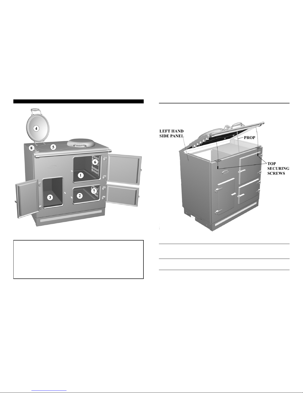
YOUR COOKER
1. Top Oven Accessories
AccessoriesAccessories
Accessories
2. Bottom Oven 1 Grillpan Handle
3. Warming Cupboard 1 Roasting Dish
4. Bolster Lid 1 Grillpan/Shallow Roasting Tray
5. Induction Hob 2 Oven Shelves
6. Removable Top Oven Shelf Support 1 Oven/Grill Shelf
7. Removable Bottom Oven Shelf Support 1 Plate Rack
8. Control Panel
Fig. 1
13
To Remove the Fan Unit from the Main Oven
Unscrew the six screws around the unit, pull the unit out with the wires attached, being careful no to allow
them to fall back into the oven. Remove the fan guard by unscrewing the fixing screws on the top and two
on the bottom of the unit.
To Remove the Induction Elements
Lift up the hinged top (see page 12).
Unbolt the 6 bolts holding the Induction support panel carefully. Each Induction coil will lift out.
To Replace the Element
Undo the 3 screws holding it, insert new element and replace wires.
To Repl ace th e Motor
Unscrew the fan blade nut, u nbolt the 3 fix ing bolts, replace motor ensuring the spac ing nuts and
wires are correct!
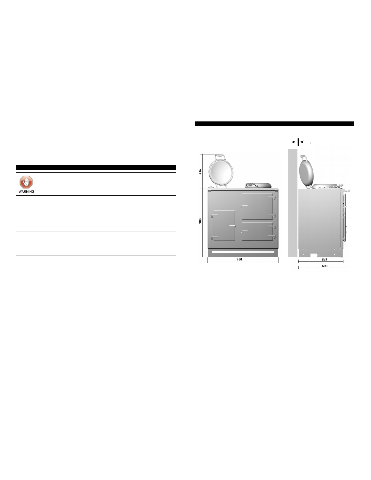
Fig. 6
Page 5
SERVICING INSTRUCTIONS
General Cleaning
Enamel is simply a coloured glass coating added to the metal to give a durable and hygienic finish. It can
be damaged by scratching or by a sudden application of cold liquids onto its surface when hot. Clean
with a cloth and soapy water, preferably while the cooker is still warm. Proprietary non-scratch liquid
cleaners for enamelled surfaces may be used. Spilled liquids should be removed as soon as possible.
Fruit juices and other acidic products can remove the gloss surface from the enamel if left for any length
of time. A stainless steel cleaner can be used for cleaning the hob lids, the door handles and the control
knobs. Do not use scouring powders or pastes, scouring pads or oven cleaners on the control panel
fascia plate as this may damage the markings.
The cooker does not require regular servicing, but has been designed so that internal components are
easy to replace in the event that they become faulty.
It is preferable that access to internal parts is made by lifting the hinged hob.
All the oven and grill elements can be removed and replaced from the front of the cooker through the
oven openings.
To hinge the Cooker Top (see Fig. 6 on Page 13)
1. Pull the unit 10mm from the back wall then undo the two screws holding the top down. Slowly lift up
the top until the limit chain stops the top lif ting up any hi gher. Pull up the prop a nd be caref ul to
positio n it c orrectl y in the rec ess on the underside of the top.
To Remove the Base Element from the Bottom Oven
1. Remove the shelves and shelf supports from the oven.
2. Remove the two screws holding down the oven base at each side. Remove the base.
3. Undo the screw fastening the element to the side of the oven. The element can then be pulled out of
the base of the oven. The electrical wire connections should stay attached to the element as it is
pulled from the oven. The element wire terminals can then be swapped from the faulty element to the
new element. Take care not to let the element wire connections fall back inside the cooker before
they are reconnected to the new element.
To Remove the Upper Elements/Grill Element from the Top or Bottom Oven
1. Undo the single screw fastening the element to the side of the oven.
2. Loosen the screws on the element support brackets. The support brackets can then be rotated clear
of the elements allowing the elements to fall.
3. The electrical wire connections should stay attached to the element as it is lowered. The element wire
terminals c an then be swapp ed fr om the faulty el ement to the new one. Take car e no t t o le t t he
element wire connec tions fall back inside the cooker before they are r econne cted to the new
element.
Isolate the electrical supply before any repair work.
12 5
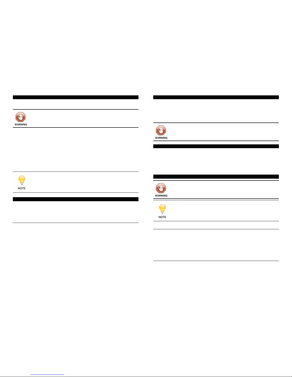
All dimensions are shown in mm.
The cooker weighs 200kg and so the floor must be capable of withstanding the load.
If the floor is not level the cooker should be made level with the use of packing pieces. The cooker does
not require access via the side panels once it is installed and so kitchen units can be butted up to the
sides of the cooker.
It is not recommended that the cooker be positioned below wall cupboards, as heat and steam from the
cooker may cause damage to the cupboard and its contents.
SPACING & DIMENSIONS
10
Fig. 2 Fig. 3
Page 6
CONNECTING THE COOKER
The mains supply cable must be s ecurel y clamp ed by the cable clamp so that any
tension applied to the supply cable must not be transmitted through to the terminal block.
For your own safety, we recommend that a competent person, such as a qualified electrician, install your
cooker. The cooker should be installed in accordance with the latest Edition of the IEE Regulations.
The cooker must be connected to the correct electrical supply (as stated on the rating plate, situated
inside the warming cupboard door) through a suitable cooker control unit incorporating a double pole
switch having a contact separation of at least 3mm in all poles, adjacent to (but not above) the cooker.
We recommend that the cooker circuit be rated to 45amps. We recommend that 6mm P.V.C. insulated
twin and earth cable is used to connect the cooker to the cooker control unit.
The cable must be BASEC or HAR approved. Preferably allow sufficient cable length for the cooker to be
pulled out if need be, but do not let it hang closer than 50mm (2") to the floor. The cable can be looped if
necessary, but make sure that it is not kinked or trapped when the cooker is in position.
We supp ly a l ength of cabl e read y to co nnect to the 45 amp switch
Access to the cooker termi nal bl ock is by lif ting t he hob , (see Fig 6, page 13).
This product complies with valid EMC standards, therefore no disturbances with other electronic devices
should occur. Users fitted with a pacemaker or other electronic implant are recommended to check with
the manufacturer of that device to ensure it is in compliance with the appropriate regulations relative to
EMC standards.
HOB SAFETY POINTS
• The cooking surface may get hot even in the case of inductive heating, as a hot pan will transfer
some heat back to the glass surface.
• Do not leave the hob switched on with the bolster down.
• It is inadvisable at any time to leave a heating element switched on without a pan in position as this
wastes energy, and could make marks more difficult to remove.
• Never cook directly on the hob surface without a cooking pan as this will result in damage to the
surface of the hob.
• Never use the hob as a worktop surface as damage may occur to the smooth surface of the hob.
• Never drag or slide pans on the hob surface, as this will cause scratches in the surface of the hob.
• Never leave any utensils, food or combustible items on the hob when it is not in use.
• Never place plastic foil, or plastic containers on the hob as damage will occur.
• Always ensure that the base of the utensil is dry before placing it on the hob.
This cooker must be earthed.
HOB
6
WARMING CUPBOARD
The warming cupb oard is not independen tly heated but picks up heat from the top and bottom
oven. The temperatur e of the warming cupboard depends on the temperatu re in the top and the
bottom oven and the length of time for which either oven has been on. As a rough guide, the warmin g
cupboard will reac h a tempera ture of 60°C after the top oven ha s been on for o ne hour. A plate rack
is sup plied in th e war ming cupboard for holdi ng up to eight plates , but this can be re moved to al low
larger items to be warmed.
Remove p lastic prot ective covers from i nner d oor li nings, lift up lid s and hinge c overs.
Before you cook for the first time, it i s r ecommended that the top and the botto m ov en b e s witched
on at f ull power for about an hour in order to burn off any in itial odours . The grill should also be
turned on, w ith the top oven door open, for approximately 15 minutes before i t is used for t he first
time. Clean the hob surface with Ceramic Hob Cleaner and Conditioner. This applies a thin prote ctive
film to the h ob, making it easier to c lean, and pro longin g its life.
Hob Cleaning
It is recommended that the hob be cleaned daily with Hob Brite cleaner. Normally cleaning should be
carried out when the hob is cooled, but, if jam, fruit or anything with a high sugar content is spilled on the
hob, or plastic or aluminium is melted onto the hob, clean it off immediately, as damage to the hob can
result. Switch off the hob and use a metal spatula, palette knife or scraper to remove the spillage. TAKE
CARE, as the spillage and the hob may be very hot.
Do not use scouring powders or paste, wire wool scouring pads or oven cleaners on the hob as these
may cause damage to the hob surface.
Oven Cleaning
Both the ov ens and th e warming cupboa rd can be c leaned u sing normal oven cl eaners. The shelf
supports in the top and bottom ovens can be removed to make cleaning easier. There is no need to try to
clean up under the grill area as this top part of the oven is self cleaning.
Never use excessive amounts of water to clean your cooker.
For your own safety, always switch off your cooker at the mains supply and allow cooling
before cleaning.
BEFORE COOKING
If the cooker is ON f or prolonged periods any plates in the warming cupboard may
become very hot.
CLEANING
11
Page 7
7
10
• Never use utensils with rough bases.
• It is important that any spillage is dealt with before the hob is used again, otherwise it may become
baked on.
• Remove any spillage of high sugar content, such as jam, immediately. Use a pan, which is large
enough to prevent boil over or spillage.
• Before using the hob for the first time we recommend you clean the glass surface with ceramic hob
cleaner and conditioner, such as Hob-brite. This applies a thin protective film to the hob, making it
easier to clean and prolonging its life.
Operation
• It is essential to use pans suitable for induction cooking. These have to have a ferrous content, so
cast iron and magnetic stainless steel are ideal but copper, aluminium and ceramic pans will not
normally work.
• There are left and right induction zones controlled separately by the 2 knobs as shown in Fig. 4.
• To turn on the zone, lift the bolster lid to expose the cooking area and turn the appropriate control
knob clockwise. The further it is turned, the higher the power.
• Temporary extra power boost is achieved by holding the control knob against the maximum setting
and manually overriding the spring resistance built in to the control.
• The hob itself does not heat up. The power will transfer directly to a pan placed on the hob.
• To reduce power and to turn the power off, turn the control knob counter-clockwise.
• Both left and right zones may be used simultaneously.
• Do not place or leave an empty pan on the hob, nor put metal utensils or objects on or too near the
hob as they may become hot.
Child Lock Function
This prevents switching on of the induction hob. Whilst activated, no cooking zone can be used.
The Child Lock mode is activated by overwinding the two knobs clockwise for more than 5 seconds, or
one or both knobs anticlockwise for more than 5 seconds.
The Child Lock is disabled by holding both knobs overwound anticlockwise for more than 5 seconds.
Pan Detection
After 10 minutes without detecting any pan, the hob switches off automatically and can only be switched
on again after the knob has been returned to the 'OFF' position first.
Before cooking for the first time please turn on the ovens and grill in order to burn off any
newness smells and manufacturing residue.
GRILL
The Grill will not operate unless the Top Oven control is in the 'OFF' position. Only use the
grill with the top oven door open.
Operation
Turn the control kn ob clockwis e to click 'ON ' the gri ll a nd c ontinu e tu rning clockwise to i ncrease the
grillin g temper ature. O r, turn an d click the g rill knob anti-c lockwise to instantly turn ' ON' the gri ll at
maximum setting. The knob can be turned clockwise or anti-clockwise back to '0' to switch 'OFF' the grill.
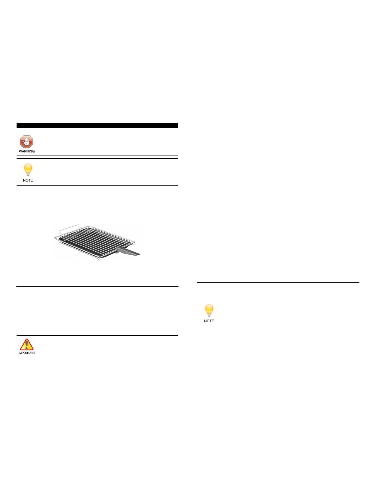
When grilling, the grillpan/sh allow bak ing tray supp lied can be slid und er the grill shelf for catching
crumbs or fat. The grillpan handle will work only if the grill tray is correctly in position under the grill shelf.
Grillpan Handle/Grill Safety Points
• When attaching the grillpan handle, make sure it is in the middle of the grillpan.
• Do not leave the grillpan handle attached to the grillpan whilst grilling, as it will become hot. Use it
only when moving the grillpan.
• Only operate the grill with the top oven door open.
Only operate the grill with the top oven door open.Only operate the grill with the top oven door open.
Only operate the grill with the top oven door open.
• Ensure that the grillpan is correctly placed between the shelf runners when grilling.
• The towel rail may become HOT after long periods using the grill.
• Do not place towels or any other items over the towel rail when grilling.
• Do not line the grillpan with aluminium foil.
Accessible parts may become hot when the grill is in use. Children should be kept away.
Grillpan Handle
Oven/Grill Shelf
Grillpan/Shallow Baking Tray
Fig. 5
The grill must never be operated with the top oven door closed.
Page 8
9
8
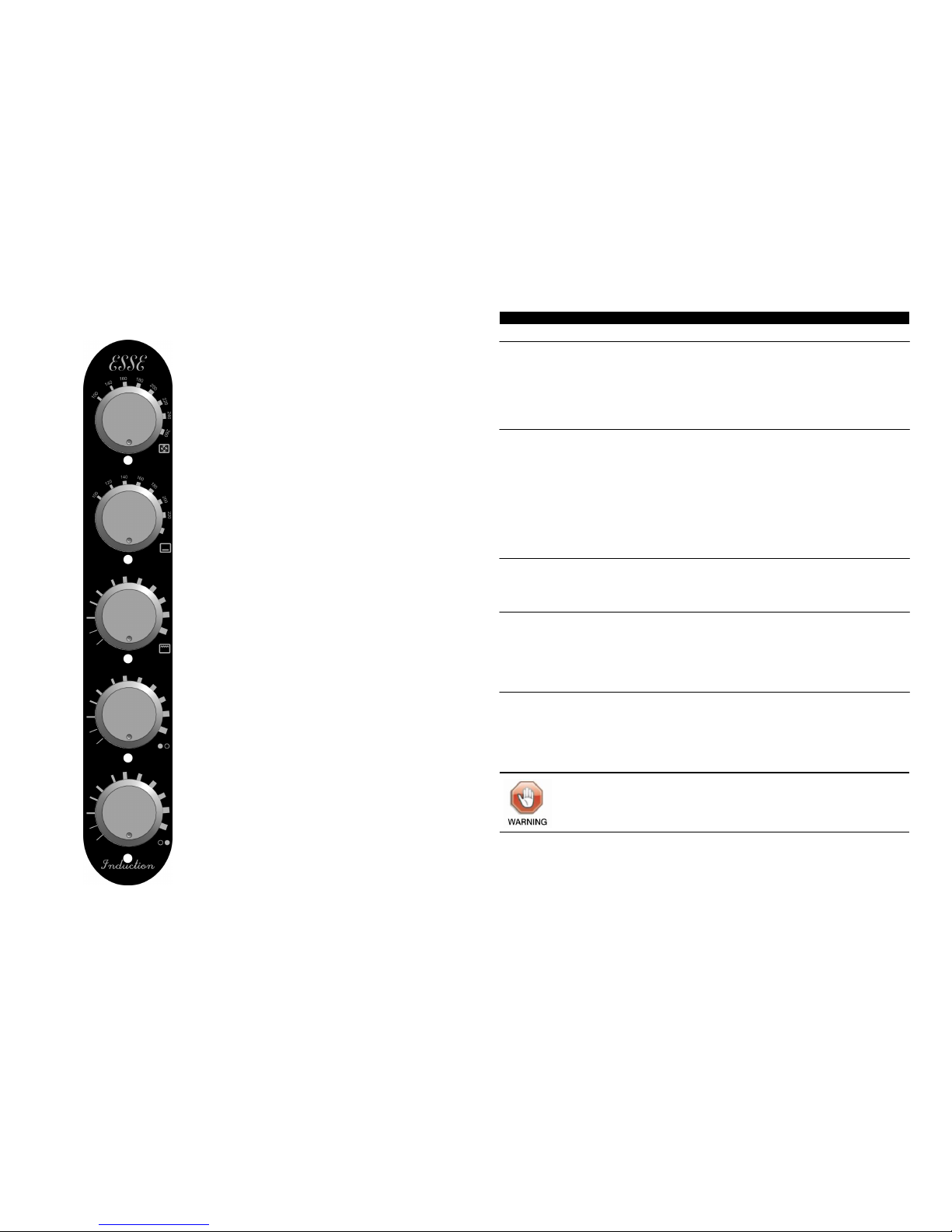
Top Oven Control
Bottom Oven Control
Grill Control
Left Side Induction Hob Control
Right Side Induction Hob Control
Fig. 4
Operation
The large top oven is fan assisted and the smaller bottom oven is conventional, both are contr olled
thermos tatical ly. To switc h on e o f t he o vens 'ON', turn the c orresp onding knob on the contr ol panel
(see Fig. 4) clockwise to the required temperature marking. The temperature markings on the control
panel are in degrees Celsius. The indicator light will illuminate to show that the oven is heating up. When
the oven reaches the required temperature the indicator light will go out. All the shelves can be used in
either the top or bottom oven.
Top Oven Temperature Guide
A thermometer in the door gives an indication of the oven temperature, but since it is in the door itself, the
thermometer will react if the door is opened and the thermometer reading may fall considerably. When
the door is closed, the thermometer will recover slowly to indicate the oven temperature.
High efficiency fan oven : It may be necessary to adjust either cooking times or temperatures if transferring
recipes from conventional ovens. For example, if a recipe states 180°C, it may require a fanned oven
temperature of 160°C. Ensure there is sufficient space around the food to allow air circulation.
As this is a high efficiency oven you may notice an emission of steam when the door is opened.
Heat distribution throughout the oven is very even, meaning there are no heat zones and no flavour transfer, thus allowing different dishes to be cooked together if required. However, if more than one item is
being cooked then cooking times may need to be increased slightly.
Heating
With the bottom oven turned on at a low setting the cooker will become warm to the touch and will radiate
heat into the kitchen. At a setting of 80°C th e botto m oven wi ll consume approximately 1/3 kW of
electricity per hour.
Condensation
Condensation will be produced when cooking food with a high water content, especially if the body of the
cooker is cold. Before cooking, pre-heat the oven until the cast iron door becomes warm, this will reduce
the amount of condensation when the food is produced.
Excess condensation may be produced when the ovens are operated for the first few times and this will
commonly show itself in the door thermometer. This will reduce each time the ovens are used.
Oven Safety Points
• When using the oven shelves ensure the shelves are correctly placed between the shelf runners.
• Always use the oven gloves provided when removing food from either the oven or grill when food is
cooked.
.
OVENS
The front, top and doors of the c ooker may become hot afte r long periods of cooking .
Keep chi ldren and p ets awa y.
 Loading...