

Page 1
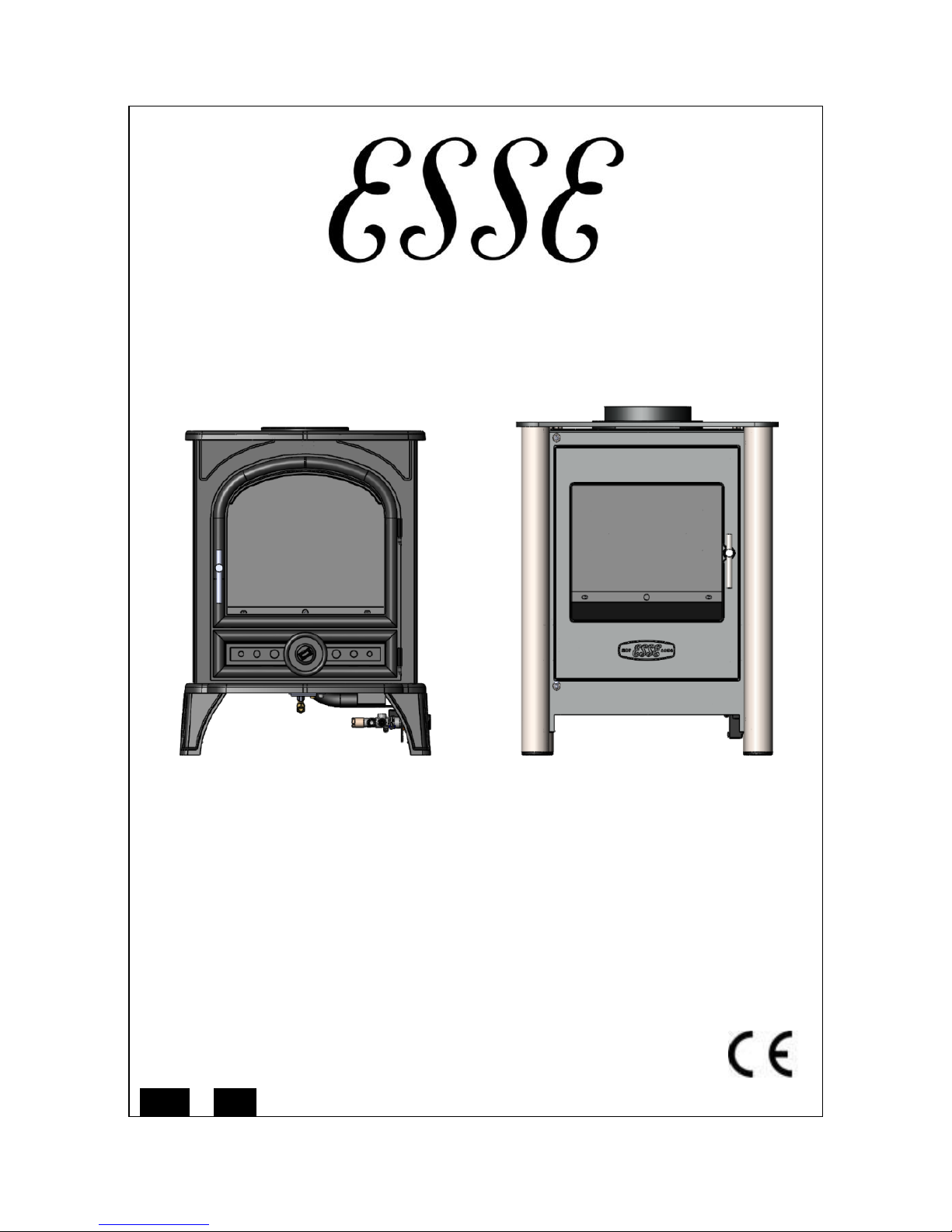
G500/G525
GAS FIRED STOVE
INSTALLATION,USER & SERVICING INSTRUCTIONS
(TO BE LEFT WITH THE CUSTOMER)
UK & IRELAND
G500/G525
For use in UK & Ireland on Natural gas at a supply pressure of 20mbar or
Propane at a supply pressure of 37mbar
GB
IE
Page 2

Page 2
G500-G525-I02-070214
INSTALLATION INSTRUCTIONS
CONTENTS
Important Notes
Page 2
Commissioning the Stove
Page 8
Technical Information
Page 3
Check for Spillage
Page 9
Dimensions and Clearances
Page 4
Customer Briefing
Page 10
Installation
Page 5
IMPORTANT NOTES
This stove is a fuel effect radiant convector. Before installation, ensure that the
local distribution condition (identification of the type of gas and pressure) and the
adjustment of the appliance are compatible. The data label is located at the rear of
the stove. The installation must be in accordance with these Instructions and
National Regulations and must be carried out by a qualified installer.
Any flue damper plate or flue restrictor must be removed or fixed permanently in
the fully open position, or shall only be fitted in accordance with National
Regulations.
If the chimney has previously been used to burn solid fuel, the chimney should be
swept before the stove is installed.
Before the stove is installed a flue test in accordance with National Regulations
should be carried out. The gas connection must be in accordance with National
Regulations.
The stove is fitted with a spillage monitoring system consisting of a thermal switch
connected to a thermocouple interrupter. This system is not adjustable, and must
not be put out of action. If any parts of the spillage monitoring system require
replacement only original manufacturers’ parts must be used.
All surfaces except the control knob and battery housing are considered to be
working surfaces.
The stove should not be used for any other purpose than as a room heater and a
decorative stove.
Page 3

Page 3
G500-G525-I02-070214
TECHNICAL INFORMATION
Natural Gas Settings
G500/G525
GAS
GATEGORY
I
2H I2L
HEAT INPUT (NETT)
HIGH/LOW
4.87kW/1.96kW
4.87kW/1.96kW
SUPPLY PRESSURE
20 mbar
25 mbar
INJECTOR SIZE
82/320
82/320
GAS CONNECTION
8mm O.D. Tube
8mm O.D. Tube
COUNTRIES OF
DESTINATION
CH, CZ, ES, FI, GB,
IE, IT, PT & SE
NL
LPG Settings
G500/G525
GAS
GATEGORY
I3P
HEAT INPUT (NETT)
HIGH/LOW
4.23kW/1.96kW
SUPPLY PRESSURE
37 mbar
INJECTOR SIZE
92/130
GAS CONNECTION
8mm O.D. Tube
COUNTRIES OF
DESTINATION
CH, CZ, ES, FR, GB,
IE & PT
Page 4
Page 4
G500-G525-I02-070214
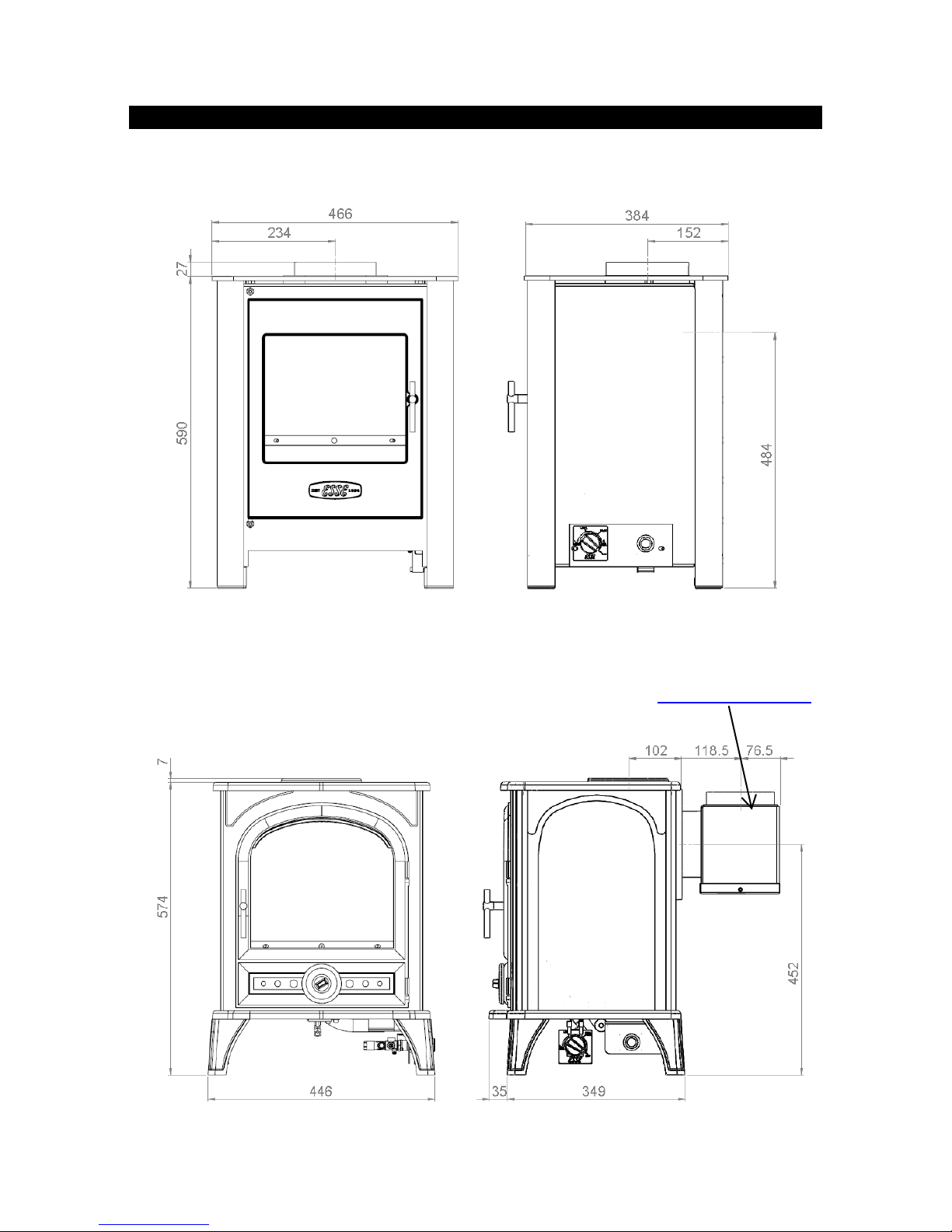
DIMENSIONS AND CLEARANCES
Fig 1a – G525 Dimensions
Fig 1b – G500 Dimensions
Optional rear flue attachment available from www.esseparts.com
Page 5

Page 5
G500-G525-I02-070214
INSTALLATION
Install the stove in accordance with the requirements given below. If a concealed gas
connection is to be made prepare the pipe work prior to installing the stove.
Positioning the Stove
Clearances from non-combustible material in the fireplace opening must be at least
50mm on the left side, 150mm on the right hand side and 75mm at the back. These
distances must be extended to a minimum clearance of 400mm from any combustible
material.
Hearth
The stove must stand on a fireproof hearth made of non-combustible material of a
minimum thickness 12mm and be of sufficient size to accommodate the stove (see
Fig.1a/b).
Fire Surround & Shelves
It is recommended that a fire surround should not be closer than 400mm from the
stove, if manufactured from a combustible material.
A combustible shelf may be fitted provided that it is not more than 150mm deep and
there is at least 400mm clearance from the top of the stove.
Coal Arrangement
The coals/logs should only be arranged as shown in the layout given in the Installation
Instructions by a qualified person.
The stove must only be fitted with the ceramics supplied. DO NOT use any extra coals or
logs.
Flue Connection
The flue should be a minimum of 3m high and at least 125mm diameter or
equivalent area.
Horizontal or negative gradients in the flue pipe should be avoided.
It is recommended that a minimum height of 610mm from the stove should be
established before any significant change in the direction of the flue.
An optional rear flue attachment is available as an accessory from
www.esseparts.com (see Fig.1b).
Page 6

Page 6
G500-G525-I02-070214
Ventilation
Ventilation should be in accordance with National Regulations. In the United Kingdom,
purpose provided ventilation is not normally required, except in new build houses.
For Republic of Ireland refer to I.S813 issued by the National Standards Authority of
Ireland.
Gas Connection
The gas supply connection is at the right hand side of the stove on the gas valve.
A nut and olive (strapped to the valve body), tail pipe and a pressure test elbow are
supplied with the stove for easy connection.
The gas supply should incorporate a service tap, be purged and any loose matter
removed.
Connect the gas supply pipe and check for gas soundness.
Page 7
Page 7
G500-G525-I02-070214
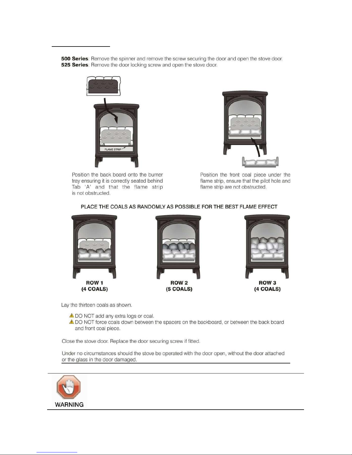
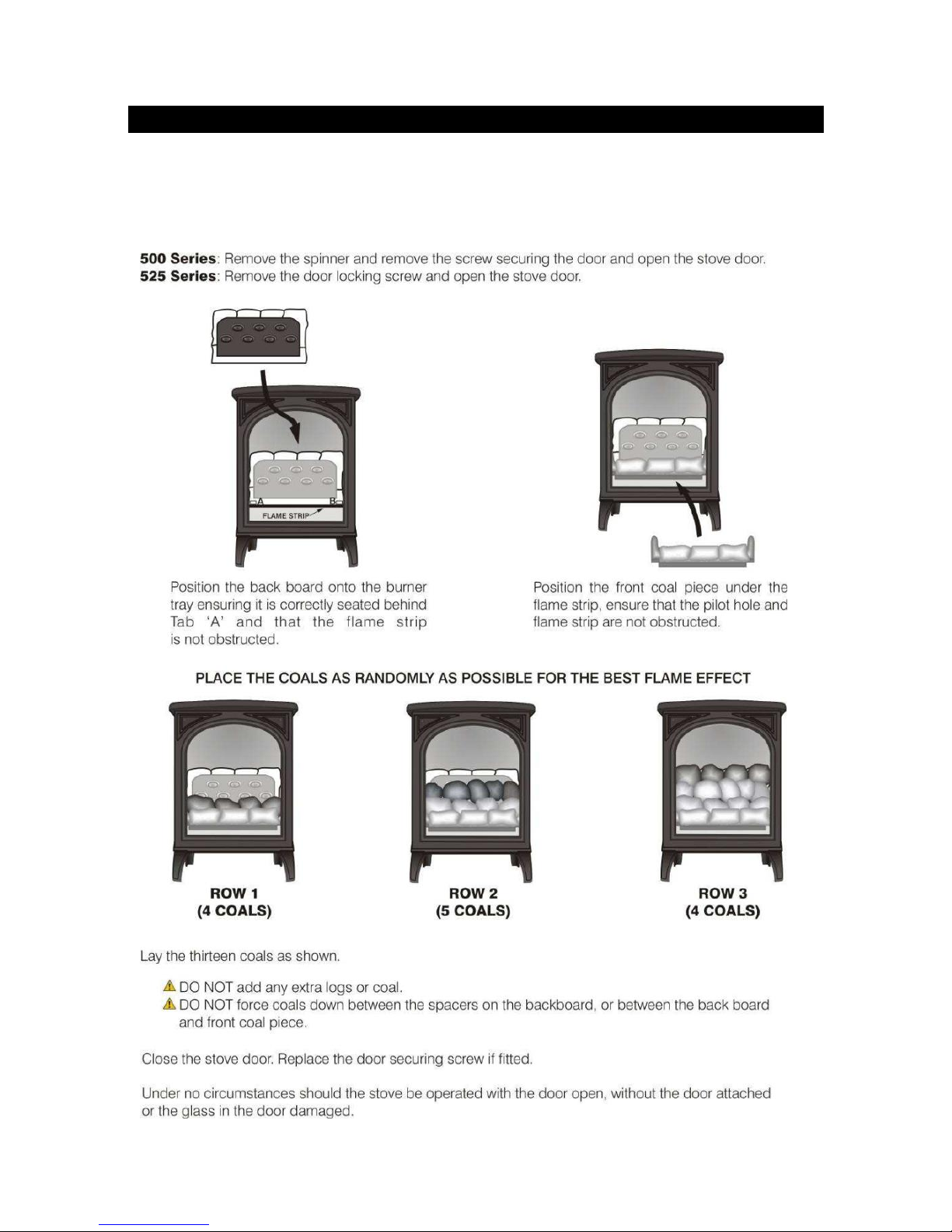
Positioning the Coals
Under no circumstances should the stove be operated with the door
open, without the door attached or the glass in the door damaged,
broken or missing
Page 8
Page 8
G500-G525-I02-070214
COMMISSIONING THE STOVE
The stove is fitted with a pilot light, pulse spark ignition and flame-sensing device.
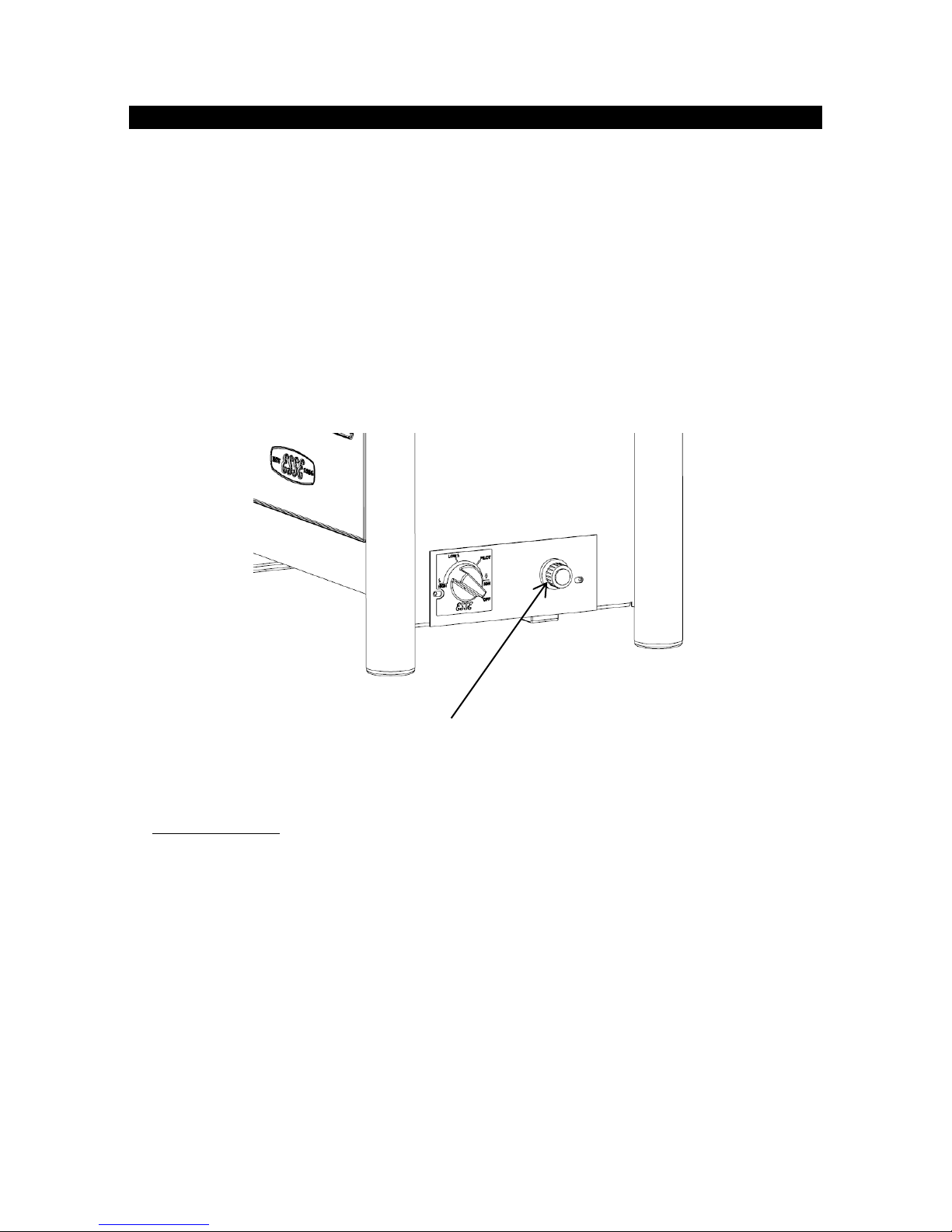
The control knob is located behind the right-hand foot of the stove.
The pilot light is centrally located.
Should the stove be extinguished for any reason wait 3 minutes before attempting
re-ignition.
Connect a suitable pressure gauge to the pressure test point.
Fit AA battery to spark generator as shown below
Fig 6 – Battery Compartment
1. Unscrew battery cover to fit battery.
2. Replace battery
3. Refit battery cover.
Lighting the Pilot
Depress control knob fully. Whilst depressed turn knob slowly through 80° anticlockwise to PILOT setting. Continue to depress the control knob, the pulse spark
ignitor should be heard and the pilot should light. Repeat until pilot is visibly lit. If
necessary, the operation of the spark can be viewed by temporarily opening the front
door.
Keep knob depressed at this point for 10-15 seconds and release the knob. The pilot
light will remain lit.
Page 9

Page 9
G500-G525-I02-070214
Low Setting
If the pilot is not already lit, light the pilot as instructed.
With control knob at PILOT setting, depress and turn anti-clockwise to LOW setting
and release the knob.
High Setting
If the stove is not already lit on LOW setting, ignite stove to LOW setting as instructed.
Turn the control knob anti-clockwise until the HIGH setting is reached. Check that the
supply pressure and/or setting pressure are in accordance with that given in the
TECHNICAL INFORMATION section.
Turning the Stove OFF
From any heat setting, depress control knob fully and turn clockwise to PILOT position.
Disconnect the pressure gauge, replace the test point sealing screw and test for gas
soundness.
Turning the Pilot OFF
From any heat setting or the PILOT position, depress control knob fully and turn
clockwise to OFF position.
Fig 7 – G500/G525 Contemporary C series control knob.
CHECK FOR SPILLAGE
Close all doors and windows in the room containing the appliance. Light the stove and
turn the control knob to ‘HIGH’, leave the appliance for 5 minutes.
Apply a smoke match along the bottom edge of the draught diverter. The installation is
satisfactory if the smoke is drawn into the stove. If in doubt wait a further 10 minutes
and then repeat the test.
Page 10

Page 10
G500-G525-I02-070214
If there is a nearby room with an extractor fan the spillage test should be repeated with
the fan running and all connecting doors between the stove and the fan left open.
If in doubt disconnect the appliance and seek expert advice.
CUSTOMER BRIEFING
Hand these Instructions and the Users Instructions to the customer.
Advise the customer how to use the stove.
Explain to the customer that the stove has a flame failure and spillage monitoring
system.
Point out the explanation of this system is in the Operating the Stove section of the
instructions.
Advise that if the monitoring system repeatedly shuts off the stove, it should be
switched off and a specialist consulted.
Advise that if the fire goes out for any reason, wait at least three minutes before re-
lighting.
Advise the customer that the stove should not be used at a lower setting than the
‘LOW’ position.
Advise the customer that due to the newness of materials the stove may give off a
slight smell for a period of time after commissioning. This is quite normal and any
odours should disperse after a few hours operation.
Stress that no extra coals must be added over and above those supplied with the
appliance and that any replacements must only be authorized ESSE spares.
Recommend that the stove is regularly serviced and the flue system checked by
qualified persons.
Installer’s Name
Installer’s Telephone Number
Installer’s Company
Appliance Serial Number
Page 11

Page 11
G500-G525-I02-070214
USER INSTRUCTIONS
CONTENTS
General Notes
Page 11
Spillage Monitoring System
Page 14
Important Notes
Page 11
Battery Replacement
Page 14
Positioning the Coals
Page 12
Cleaning
Page 15
Operating The Stove
Page 13
GENERAL NOTES
This stove has been individually designed to add charm and character to your
home. Providing a highly efficient heat source, the stove has the look and charm of
a wood burning stove coupled with the convenience of clean burning gas.
Due to the newness of materials the stove may give off a slight smell for a period of
time after commissioning. This is quite normal and any odours should disperse
after a few hours operation.
IMPORTANT NOTES
The installation must be in accordance with National Regulations and must be
carried out by a qualified installer. Under no circumstances should the appliance
be operated with the door open, without the door attached or the door glass
damaged broken or missing.
All surfaces except the control knob and battery housing are considered to be
working surfaces. Most parts of the stove will get hot during and after use. If young
children, the elderly or infirm are likely to be near the stove, then a suitable
fireguard to BS8423 is recommended.
Do not drape clothes, fabrics or other combustible materials over the stove.
Curtains must be at least 400mm above the top of the stove.
A combustible shelf may be fitted over the appliance provided that in the case of a
150mm or less deep shelf there is at least 400mm clearance above the top of the
stove.
The stove should not be used for any other purpose than as a room heater and a
decorative stove.
Page 12
Page 12
G500-G525-I02-070214
POSITIONING THE COALS
The coals should only be arranged as detailed below and by a qualified person.
The stove must only be fitted with the ceramics supplied. DO NOT use ant extra coals or
logs.
Page 13

Page 13
G500-G525-I02-070214
Under no circumstances should the stove be operated with the door
open, without the door attached or the glass in the door damaged,
broken or missing
OPERATING THE STOVE
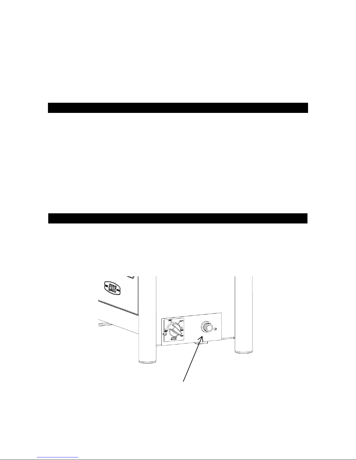
The stove is fitted with a pilot light, pulse spark ignition and flame-sensing device.
The control knob is located behind the right-hand foot of the stove.
The pilot light is located towards the front of the burner.
Should the stove be extinguished for any reason wait 3 minutes before re-ignition is
attempted.
The stove should not be used at a lower setting than the LOW position.
Lighting the Pilot
Depress control knob fully. Whilst depressed turn knob slowly through 90° anticlockwise to PILOT setting.
Continue to depress the control knob, the pulse spark ignitor should be heard and the
pilot should light. Repeat until pilot is visibly lit.
If the pulse spark generator cannot be heard, the battery may need replacing – see
page 14.
Keep knob depressed at this point for 10-15 seconds and release the knob. The pilot
light will remain lit.
Low Setting
If the pilot is not already lit, light the pilot as described above.
With control knob at PILOT setting, depress and turn anti-clockwise to LOW setting
and release the knob.
High Setting
If the stove is already lit on LOW setting, ignite stove to LOW setting as described
above.
Turn the control knob progressively in an anti-clockwise direction until the desired
level is achieved, up to the HIGH setting.
Page 14
Page 14
G500-G525-I02-070214
Turning the Stove OFF
From any heat setting, depress control knob fully and turn clockwise to PILOT position.
Turning the Pilot OFF
From any heat setting or the PILOT position, depress control knob fully and turn
clockwise to OFF position.
SPILLAGE MONITORING SYSTEM
The stove is fitted with a spillage monitoring system which senses any excess
temperature due to a flue restriction or blockage. In this event the gas supply is
automatically turned off.
Should this occur then turn the control knob to the OFF position and wait approximately
10 minutes for the switch to automatically reset. Re-light the stove as described in
OPERATING THE STOVE section (page 13). If the stove repeatedly shuts itself off, DO
NOT use the stove and have the flue system checked by a qualified person.
This spillage monitoring system is not adjustable and must not be put out of action.
BATTERY REPLACEMENT
The battery required is a good quality AA size. This should only be replaced when the
stove is cold.
Fig 11 – Battery Compartment
1. Unscrew battery cover to fit battery.
2. Replace battery
3. Refit battery cover.
Page 15

Page 15
G500-G525-I02-070214
CLEANING
Ensure that the stove is turned off before cleaning and is cold.
DO NOT use abrasive cleaning agents.
The stove is supplied with ceramic coals that should only be cleaned and arranged by a
qualified person in accordance with the Installation Instructions.
SERVICING
It is essential that the stove is regularly serviced, and the flue system checked by a
qualified person.
Servicing Instructions
The stove is fitted with a spillage monitoring system consisting of a thermal switch
connected to a thermocouple interrupter. This system is not adjustable and must not be
put out of action. If any parts of the spillage monitoring system require replacement
only original manufacturers’ parts must be used.
The thermal switch rating is 120°C. Quote this rating if ordering a new switch.
1. The following servicing procedure should be carried out regularly and only by a
qualified person.
Ensure that the fire is turned off and is cold.
2. If fitted, remove the screw securing the door handle and open the stove door.
3. Remove the ceramics in the reverse order to that described in POSITIONING THE
COALS section (p.7).
4. Remove and deposition of dirt, lint etc. carefully from the burner flame strip, tray
and pilot assembly with a soft brush.
5. Due to the intense temperatures reached in the fire, some surface cracks may
appear on the ceramic components. This is quite normal and will not affect the safe
operation of the fire.
6. Replace the ceramics as described in the POSITIONING THE COALS section (p.7).
7. Close the stove door; replace the screw securing the door handle or door.
8. Check the supply pressure as described in the TECHNICAL INFORMATION section
(p.3).
9. Ensure correct operation of the flue as described in CHECK FOR SPILLAGE section
(p.9).
Page 16

Page 16
G500-G525-I02-070214
ESSE Engineering Limited, Ouzledale Foundry, Long Ing, Barnoldswick, Lancashire
BB18 6BN
Tel. 01282 813 235, Fax: 01282 816 876
Website and On-line Store http://www.esse.com
 Loading...