

Page 1
firewall
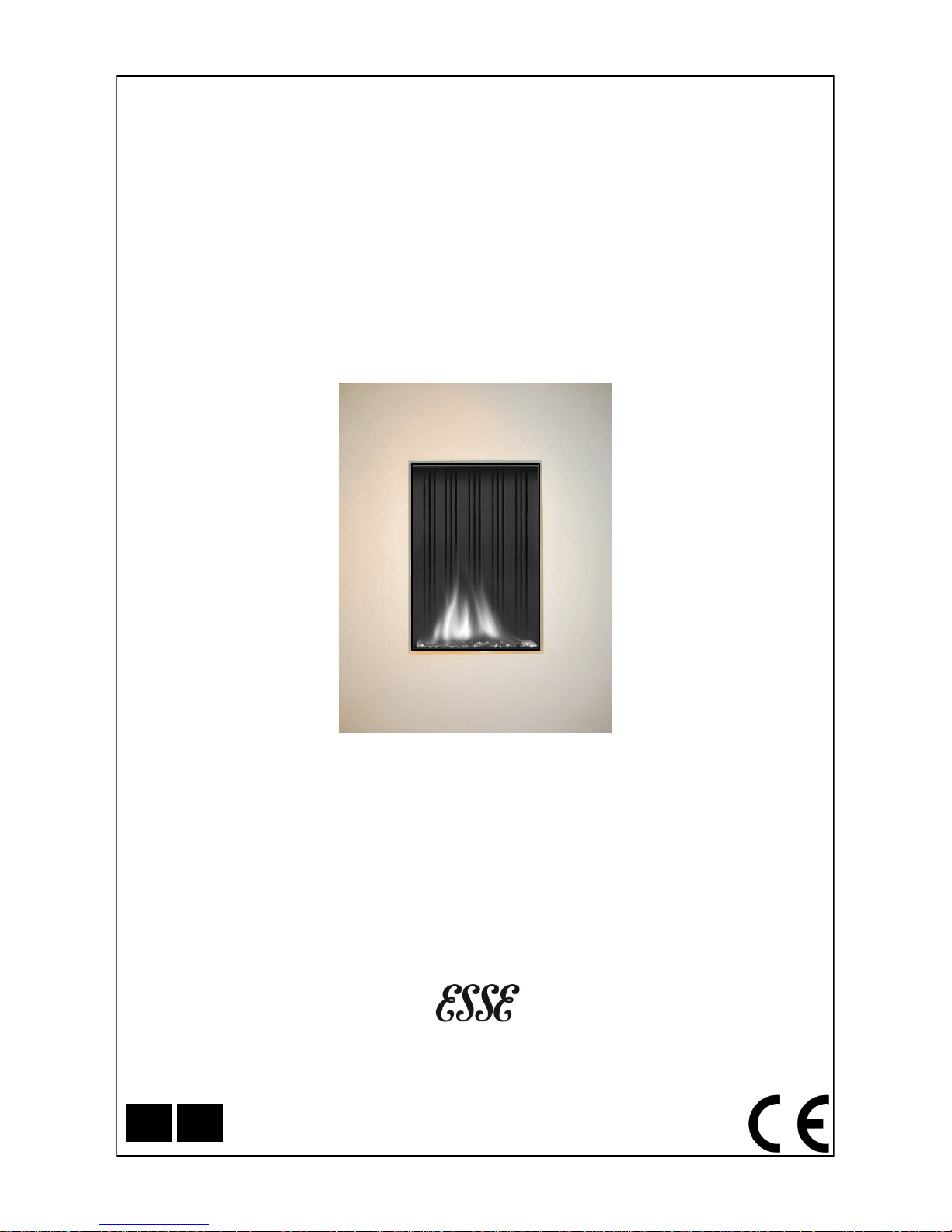
FLUELESS CAT GAS FIRED HEATER
Model: 39” Original
Fully Remote Control
USER INSTRUCTIONS
(TO BE LEFT WITH THE CUSTOMER)
For use in the UK & Ireland on Natural gas at a supply pressure of 20 mbar
or Butane/Propane at a supply pressure of 28 mbar/37 mbar
ESSE Engineering, Long Ing, Barnoldswick, Lancashire BB18 6BN
Tel: 01282 813235 Fax: 01282 816876 Email: [email protected] Website: http://www.esse.com
GB IE
Page 2

CONTENTS
Introduction to Firewalls Page 2 Ventilation Page 7
Important Notes Page 2 Burner Arrangement Page 7
Clearances Page 3 Control for the Heater Page 7
Batteries in Handset Page 4 Combustion Monitoring
System
Page 8
Handset Operation Page 5 Cleaning Page 8
Set the Electronics Code Page 6 Servicing Page 8
Page 3
1. INTRODUCTION TO FIREWALLS
This heater has been individually designed to add charm and character to your home and provides a highly
efficient heat source, coupled with the convenience of clean burning gas. Due to newness of materials the
heater may give off a slight smell for a period of time after commissioning and fully remote control. This is
quite normal and any odours should disperse after a few hours operation. It is recommended that the heater is
used only as a secondary heat source. An electrical appliance such as a television should not be fitted above
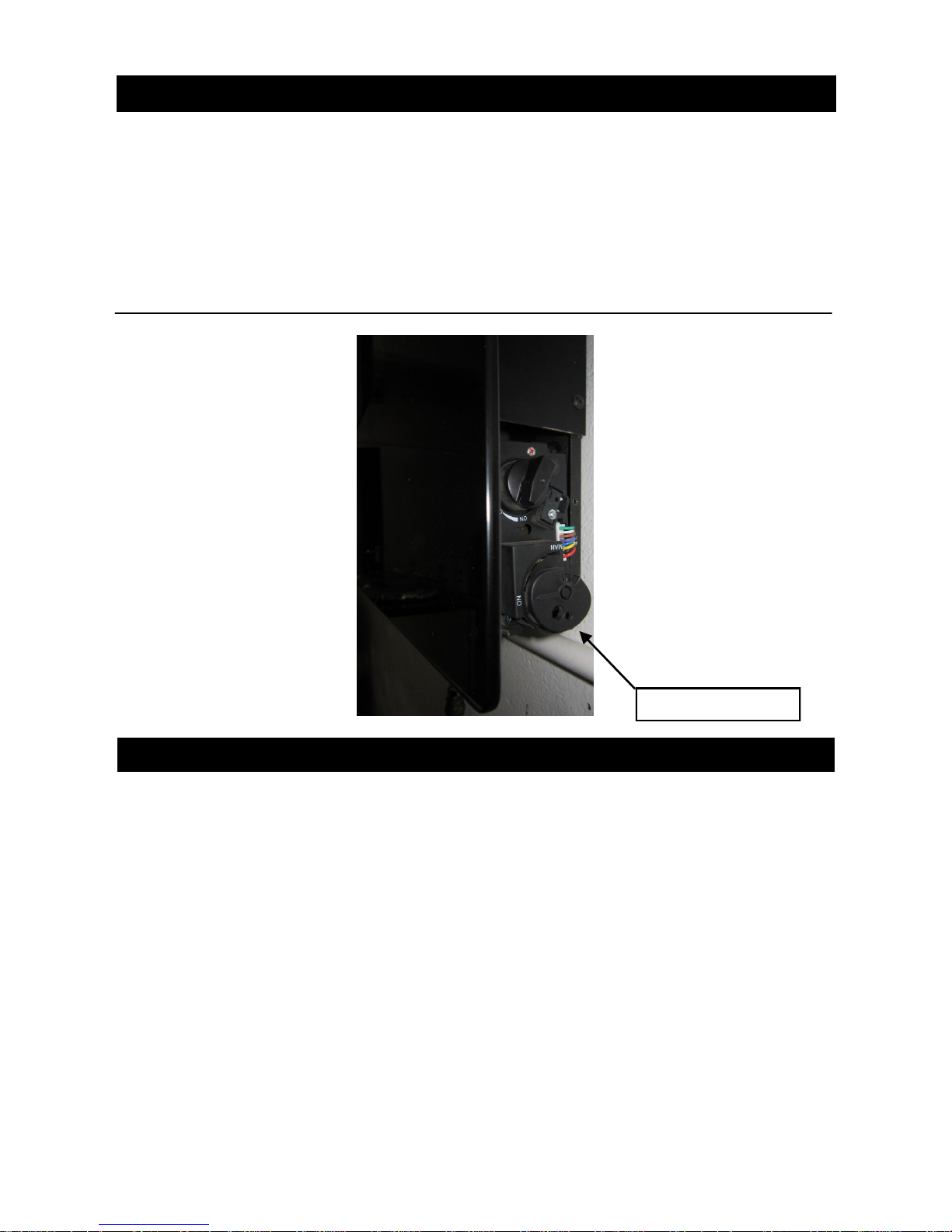
the appliance. It has been supplied for use on Natural Gas or LPG. The data plate is situated on the bottom
tray (fig. 1 - steel version) or on the backplate (glass version)
Fig.1. Control knob of Firewall
Remote Valve Control
2. IMPORTANT NOTES
The installation must be in accordance with National Regulations and must be carried out by a qualified person. Under no circumstances should the appliance be operated without the glass frame attached or the glass
damaged. All surfaces except the controls are considered to be working surfaces. Most parts of the heater will
get hot during and after use. If young children, the elderly, or infirm are likely to be near the heater a suitable
fireguard, conforming to BS8423, is recommended. Do not place any objects on top of the heater. In particular
never cover or partially cover the grille. The integral catalyst should be checked by the installer upon servicing
to ensure that there are no defects or obstructions. The expected life of the catalyst is in excess of 10,000
hours (10 years of normal use). After this time the catalyst should be replaced. Due to the high temperature
reached within the heater, surface cracks may appear on the backboard behind the flames, this is quite normal and will not affect the safe operation of the heater. The room that the heater is installed in must not be
used as a bedroom or sleeping area.
Page 2
Page 4

WARNING!
There are always dust particles in the air in every living space, even if it is regularly
vacuumed! These particles are visible in rays of sunlight and they will not bother you
as long as the concentration of particles in the air remain low. The indoor climate can
only be described as bad if these particles are floating through the room in large qualities for any reason whatsoever and if the air is additionally polluted by soot and tar
particles caused by the burning if oil lamps for example, and by smoking cigarettes
and cigars. In a heated living space, cooled air slowly streams across the floor to the
combustion appliance. The air is heated in the convection system of the heater, causing a fast rising column of warm air to develop, which then spreads throughout the
room again. As a consequence, this air always contains dust and other pollutant particles that may leave deposits on cold and often damp surfaces. This is potentially a
particular problem in new buildings that are not yet dry (construction moisture). An
unwelcome result of this phenomenon could be discolouration of walls and /or ceilings.
Wait at least 6 weeks before firing a newly bricked room or after renovations, since the
construction moisture must have disappeared completely from the walls, floor and
ceiling. The room where the appliance is located must be well ventilated and the required ventilation must be in compliance with the Installation Instruction. Do not use
candles or oil lamps. These provide considerable quantities of pollutant and unhealthy
soot particles in your home. Smoke from cigarette and cigars contain tarry substances,
which may also leave deposits on colder and damp walls when heated. If the interior
climate is bad, this phenomenon may also occur above radiators and lighting fixtures
and at ventilation grilles, although to a lesser degree. If decorating around the heater
ensure that adequate precautions are taken to prevent paint etc from coming into
contact with the heater. Do not use masking tape on the front panel.
3. CLEARANCES
To electrical devices - Under no circumstances must any electrical device (e.g Plasma T.V.) be wall mount-
ed above a firewall.
To combustibles - Minimum clearance to the sides of the heater are 100 mm (4in) but curtains, drapes and
other fabrics are not permitted within a distance of 500 mm (20 in) of the stove sides. No such materials are
permitted directly above the heater regardless of distance. Clearances to the front of the heater is 1000 mm
(39 in). A combustible shelf may be fixed to the wall above the heater, providing that it complies with the dimensions given below and is rated a minimum of 100°C otherwise discolouration or smells may occur. If in
doubt refer to the shelf manufacturer. The shelf depth may be increased up to a maximum of 457mm (18") but
the height must also be increased accordingly. An increase in height of 25 mm is required for every 12.5 mm
of additional shelf depth. For shelves that are too low, protective devices can be used such as metal heat
deflectors, but it must be assured that the shelf does not reach an unacceptable temperature before relying on
such a solution.
Maximum depth of
shelf
Minimum distance from top of
outlet grille to underside of shelf
75mm (3in) 305mm (12in)
150mm (6in) 457mm (18in)
457mm (18in) 1067mm (42in)
As with all heating appliances, any decorations, soft furnishings, and all coverings (i.e.
flock, blown vinyl and embossed paper)
positioned too close to the appliance may
discolour or scorch.
Page 3
Page 5
4. BATTERIES IN HANDSET
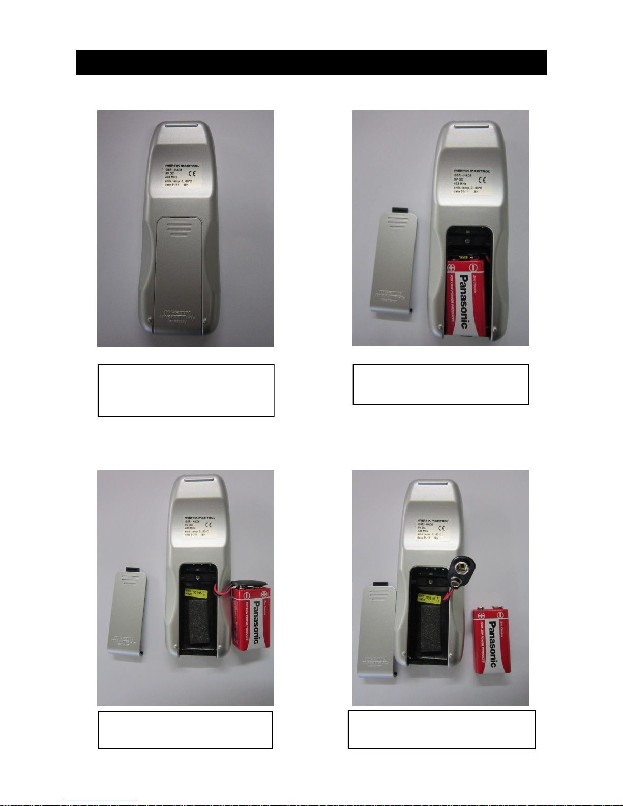
Fig. 2a Handset on the reverse side
Fig. 2b Battery inside the handset
Fig. 2c Separate Battery from Handset
Fig. 2d Battery removed from Handset
Place the Handset on the reverse side
and locate the battery compartment ,
push the panel down to release.
Locate the Zinc Chloride Battery (9V) in
battery compartment.
Take Battery from the compartment
ready for removal.
Unpop the Battery from the black panel
attached to the wires.
Page 4
Page 6
5. HANDSET OPERATION
Page 5
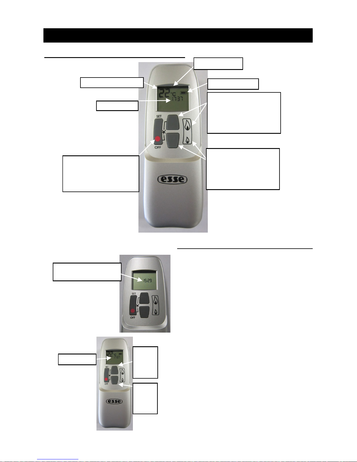
DISPLAY SCREEN
BATTERY CONTENT
TEMPERATURE DISPLAY
TIME DISPLAY
OFF BUTTON:
Hold the OFF button to
turn off the appliance.
LARGE FLAME BUTTON:
Press LARGE FLAME
button to increase the
flame.
SMALL FLAME BUTTON:
Press SMALL FLAME
button to decrease the
flame.
Fig. 3a
TIME DISPLAY
SETTING THE TIME
The Time display will flash after
either:
A. Installing the battery or
B. Simultaneously pressing the
LARGE and SMALL flame buttons.
Press LARGE Flame button to set
the hour.
Press SMALL Flame button to set
the minute.
Press OFF or simply wait to return
to manual mode.
LARGE
FLAME
Button
SMALL
FLAME
Button
TIME DISPLAY FLASHING:
TIME IS READY TO BE SET.
Fig. 3b
Page 7
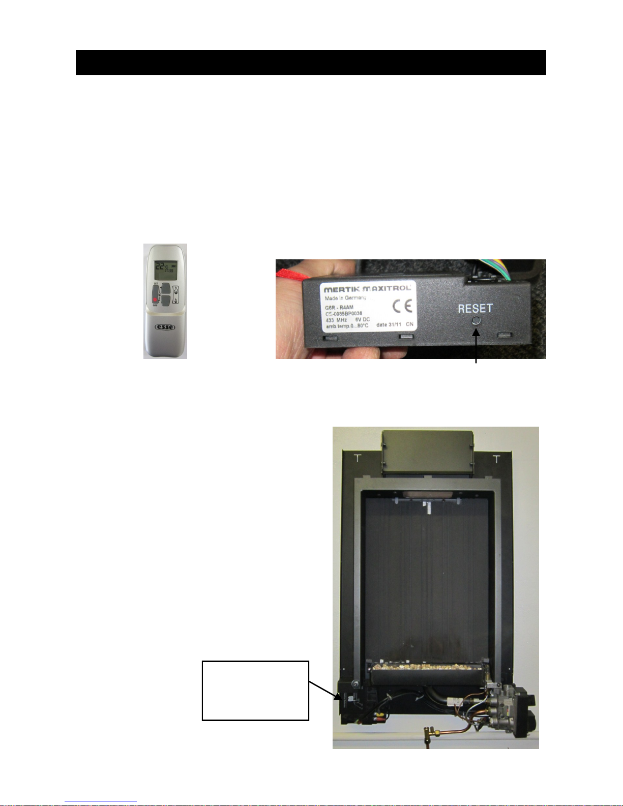
6. SET THE ELECTRONICS CODE (FIRST TIME USE ONLY)
Locate the Receiver
box underneath the
Firewall frame on the
left hand side.
A code is selected automatically for all Mertik Maxitrol electronics from among 65000 random
codes available. The receiver has to learn the code of the handset:
Press and hold the receivers reset button (see Fig 4b) until you hear two beeps. The first beep
is short and the second beep is long. After the second beep, release the reset button.
Within the subsequent 20 seconds, press the small flame button on the handset until you hear
two additional short beeps confirming the code is set. If you hear one long beep then this indicates the code learning sequence has failed or the wiring is incorrect.
Note: This is a one time setting only and is not required after changing the batteries or the
handset or receiver.
Fig. 4a—Radio frequency handset Fig. 4b—Receiver (with 4 x 1.5AA batteries)
Fig. 4c—Firewall (without glass frame)
Page 6
Page 8
7. VENTILATION
Purpose provided ventilation of 100cm2 is required for this heater. This ventilation must never be blocked or
partially blocked. An openable window or equivalent is also required. Ventilation fitted under, or within immediate vicinity of the heater must not be used as it may adversely effect performance of the combustion monitoring system (ODS) system. The requirements of other appliances operating in the space or room must be
taken into consideration when assessing ventilation requirements, this will have been carried out by your
CORGI registered installer. A supply of fresh air into the room is advisable to maintain temperatures within
limits. The heater MUST NOT be installed in a bedroom, bathroom or any sleeping area. Additionally for
L.P.G. – the heater must not be used in cellars or basements.
8. BURNER ARRANGEMENT
The burner should only be used with vermiculite granules as shown in the Installation Instructions. The heater
must only be fitted with the vermiculite supplied. DO NOT add any extra logs or coals.
9. CONTROL FOR THE HEATER
The heater is fitted with a pilot light which is also an oxygen depletion sensor (ODS), piezo spark and flame
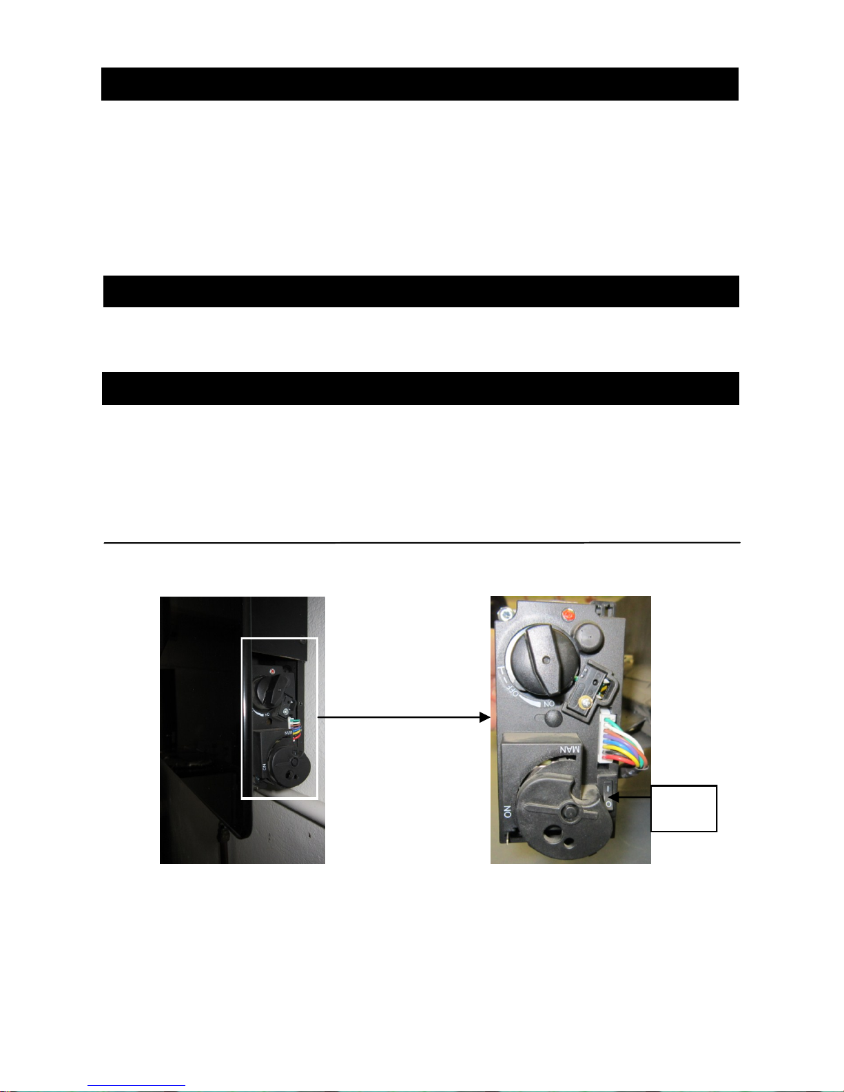
sensing device. The control is located behind the front panel on the lower right hand side (Fig 2). The pilot light
is located at the right hand end of the burner. Should the heater be extinguished for any reason wait 3 minutes
before re-ignition is attempted. The heater should not be used at a lower setting than the ‘LOW’ position.
Fig 5. Side View of Valve
Page 7
Fig 5a
Fig 5b
ON/OFF
Switch
Page 9

TURN OFF GAS TO APPLIANCE
1. Place ON/OFF switch in 0 (OFF position). See Fig 5b.
If gas control is accessible turn main valve knob to the OFF full clockwise position.
3. Replace appliance access cover (if applicable).
BATTERY REPLACEMENT
Handset—When the battery needs changing the low battery indicator will appear on the display. Use a 9 volt
quality Alkaline type. Replacement is recommended every two years.
Receiver—When the batteries need changing frequent bleeps can be heard for three seconds when the motor
turns. The appliance should be cold, remove the receiver box from underneath the appliance and replace the
batteries with 4 x 1.5 volts “AA” type quality Alkaline.
10. COMBUSTION MONITORING SYSTEM
This heater is fitted with a combustion monitoring system device (ODS). If the heater shuts off during use for
no apparent reason then several reasons may be suspected. If a door or window has been opened creating a
draught, then pilot disturbance could be the problem and removal of the draught should resolve this. The
heater can then be re-lit in accordance with the previous section. If pilot disturbance is not the cause, then the
ODS safety system may be in operation. Switch the heater OFF; call in your installer to check the heater and
ventilation. Remedial work must be carried out as required. DO NOT allow the heater to be used until the
heater and installation is passed as safe. If the pilot continues to be extinguished, you must call your installer
to check the operation of the complete heater.
11. CLEANING
Ensure that the heater is turned off before cleaning and is cold. DO NOT use abrasive cleaning agents. Glass
panels can be cleaned with a suitable glass cleaner. Test on a small area first.
12. SERVICING
It is essential that the heater is regularly serviced at least annually.
Page 8
Page 10

ESSE Engineering, Long Ing, Barnoldswick, Lancashire BB18 6BN
Tel: 01282 813235 Fax: 01282 816876
Email: [email protected] Website: http://www.esse.com
05/12 (PP)
INSTR.FW-39/u
 Loading...