

Page 1
Ouzledale Foundry Co. Limited, Long Ing, Barnoldswick, Lancashire BB18 6BN
Tel: 01282 813235 Fax: 01282 816876 Email: [email protected]
Website: http://www.esse.com
M
odel:
Serial Number:
Colour:
INFORMATION FOR USE WHEN ORDERING SPARES:
07/07
CONDITIONS OF GUARANTEE
Your ESSE cooker is guaranteed against defects arisingfrom faulty manufacture for two years, subject to thefollowing express conditions:
• A suitably qualified personmust installthe cooker, and upon installationthe detailsmust berecorded on thewarranty cardand registered
with ESSE by returning the correctly completed card. The guarantee periodcommences upon delivery of the cooker.
• The cooker has been used for normal domestic purposes only, and in accordance with the manufacturer’s instructions.
•
The cooker has not been serviced, maintained, repaired, taken apart, or tampered with by any personnot authorised by us.
• An approved dealer or representative must undertake all service work under this guarantee.
•
Any cooker or defective part replaced shall become the Company’s property.
EXCLUSIONS
This guarantee does not cover:
• Damage or calls resulting from transportation, improper use or neglect.
• Parts deemed to be replaceable in the normal usage of the cooker;e.g. thermostats, elements, etc.
• Control Panel Markings; these can become damaged if a hard abrasive isused.
• Ceramic Glass Hob; any inherent flaw or defect in the ceramic glass will be immediatelyevident.
• Enamel damage;the vitreous coating on yourcooker is in effectan extremelythin layer of glassand assuch displays all thecharacteristics
of glass. It can easily be damaged by impact, or by spillage of cold liquids onto a hot surface. Such damage cannot be covered under
this guarantee. (See also intermittent use of your cooker, below).
This guarantee is personal to the original purchaser and is non-transferable.
INTERMITTANT USE OF YOUR COOKER
In the event of intermittent use and prolonged shutdown, itshould be noted that in somecircumstances enamel might be displaceddue to
ingress of damp. Whilst this is rare, it is mostlikely to occurin situations where theunused cooker remainsin an unheated property. There
is a layer (known as the groundcoat) between the vitreous enamel surface and the cast iron. Groundcoat is porous and if exposed (e.g.
after a chip in the vitreous enamel coat), may allow damp to penetrate behind the vitreous enamel and spread through the groundcoat.
Surface oxidisation of the cast iron may thereafter occur, causing the vitreous enamel to fall off. Such damage will not be covered by your
warranty. Werecommend thata light coating of petroleum jellybe applied to any damagedareas whenthe cookeris not in use tohelp keep
out the damp.
CUSTOMER CARE
In the event you should require spare parts, please order through your e ESSE dealer.
Should you havecause fordissatisfaction with your cooker, you shouldcontact yourESSE dealer who will, inmost instances,be able to offer
you immediate assistance. You will be required to give the following details:
• Your name, address and postcode.
• Your telephone/contact details.
• Clear and concise details of the fault.
• Model and serial number of the cooker (found on the data plate inside the warmingcupboard on the back face).
• Purchase date (please note that a valid purchase receipt or guarantee documentation is required for in-guaranteeservice calls).
We will then check that we have an accurately completed warranty card, if notthen any work carried out may be charged.
The nature of the complaint will be assessed and either replacement parts for your dealer to fit, an engineer to inspect & report, or an
engineer to remedy will be arranged. If the fault is not actually due to faulty workmanship but some other cause such as misuse or failure
to install correctly, a charge will be madeto cover the cost of the visit and anynew parts required, even during the warranty period.
ESSE Electric
OPERATING & INSTALLATION INSTRUCTIONS
Page 2
2
Introduction
contents
Technical data
3
We are pleased that you have chosen an ESSE cooker. We would ask you to read the following
instr uctions very ca refully. Correctl y inst alled and operated, your E SSE co oker w ill gi ve satisfactory
servi ce for many years.
We f eel ce rtain t hat you will e njoy th e warmth and comfor t of your E SSE co oker and, per haps mo re
impor tantly, y ou wil l more than enjoy the superb qualit y of the cooking.
Unpacking
Boiler model
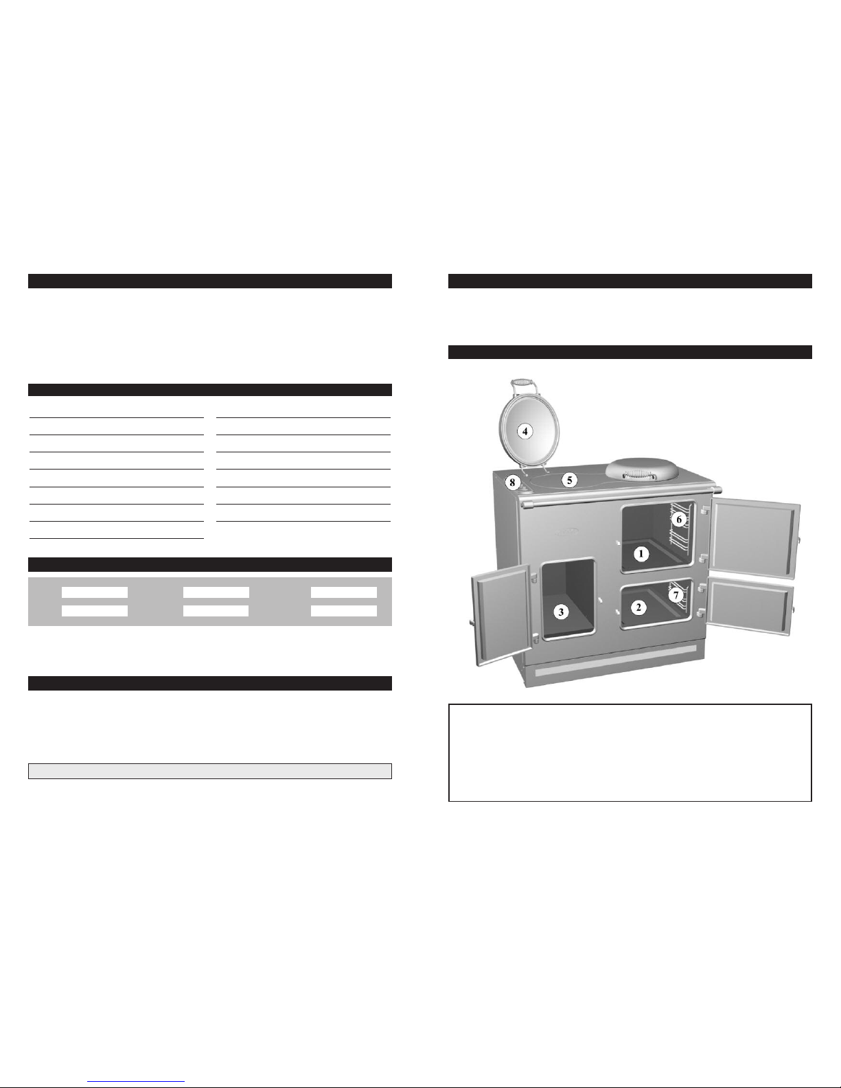
Your cooker
After unpacking the cooker, remove all the packing from the top and the bottom ovens inclu ding
protective door liners. Examine the cooker for any damage, particularly to the hob glass. Make sure
there are no chips or cracks.
If there is an y damage to the cooker or anything is missing, please c ontact your supplier f or advice.
REGISTERED DESIGN GB 2096532 PATENT PENDING
The c ooker Data Plate is located i nside the warming cupb oard on the back face.
For cookers with a buil t in gas con densing boiler see also the separately supplied booklets on installing
and using the boiler. T he boiler model cookers do not contain a warming cupboard as ref erred to in
these instructions as the cupboard is replaced by the boiler unit.
Note: If the hob is cracked the cooker must not be connected, and no part of it may be used.
Technical data Page 2
Your Cooker Page 3
Boiler Model Page 3
Spacing & Dimensions Page 4
Connecting the Cooker Page 5
Hob Page 5
Operation Page 6
Pans & Ovens Page 6
Grill Page 8
Warming Cupboard Page 9
Before Cooking Page 9
Cleaning Page 9
Servicing Instructions Page 10
Wiring Table Page 12
Wiring diagram Page 14
1. Top O ven
2. Bottom Oven
3. Warming Cupboard (Non Boiler Model)
4. Bolster Lid
5. Ceramic Hob
6. Removab le Top Ov en She lf Sup port
7. Removab le Bot tom Ov en She lf Sup port
8. Control Panel
Acces sories
1 Grillpan Handle
1 Roasting Tray
1 Grillpan /Shallow Roasting Tray
2 Oven Shelves
1 Oven/Gri ll She lf
1 Plate Rack
- 250 V
ESSE, ELECTRICESSE, ENGLAND
9kW
INPUT SERIAL NO.
MODEL
SUPPLY
VOLTAGE
50 Hz a.c.
Page 3
54
Hob
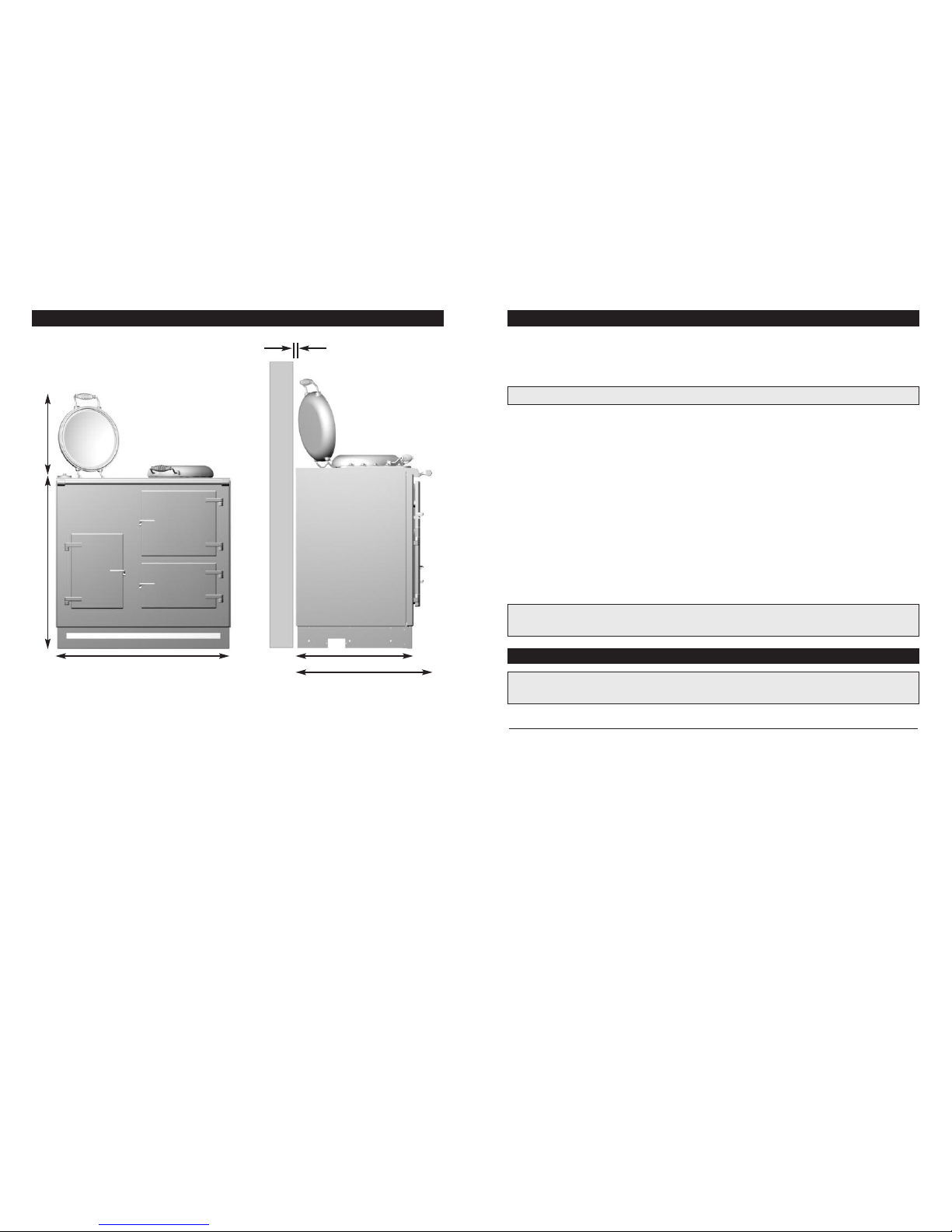
Spacing & dimensions Connecting the cooker
The cooker weighs 200kg and s o the floor must be capa ble of withstandin g the load. The cooker
stands 900mm high an d so will b e the same height as sta ndard kitchen u nits without th e use of a
plinth .
If the fl oor is not level t he cook er shoul d be made l evel wi th the use of pack ing pie ces. The cooker
does not require access via t he side panels once it is installed and so kitchen units can be butted
up to the sides o f the cooker.
It is imp ortant t hat a 10mm gap is left be tween t he ename lled cooker top and the back wall. This is
to allow the coo ker top to hing e up for ac cess to internal components. It is not recommend that the
cooker be positioned below wall cu pboards, as he at and steam from the co oker may cause
damage to the cupboard and i ts cont ents.
For your own safet y, we recommend that a competent person, such as qualified electrician , insta ll
your cooker. T he cook er shoul d be installed in accordance with the lates t Edition of the IEE
Regula tions.
The cooker must be con nected t o the correct electrical supply (as sta ted on the rati ng plate,
situat ed inside the warming cupboard on th e back face) th rough a suitable cooker control unit
incorp orating a doub le pole switch having a cont act sepa ration of at least 3mm in all poles,
adjace nt to (but not above) the cooker. We recomme nd that the cooker circ uit be rated to 45 amps .
We r ecommend that 6mm P.V.C. insulated t win and earth c able is used to connect the cooker to
the cooker control unit.
The cable must b e BASEC or HAR approved. Prefera bly allo w suffi cient ca ble len gth for the cooker
to be pul led out if need be, but do not let it hang clo ser than 50mm (2”) to the floor. The cable c an
be looped if nec essary, but make su re that it is not kinked or tra pped whe n the cooker is i n
positi on.
Access to the cooker terminal block is ga ined by removing the left ha nd side cooker panel
(see TO R EMOVE THE SIDE PANEL page 1 0).
900
416
900 565
10
600
All dimensions are shown in mm
Warning ! This cooker m ust be earthed.
Note: The mains supply ca ble must be sec urely cl amped b y the cable clamp so tha t any tension
applie d to the su pply cable must not be transmitte d throug h to the te rminal block.
Warning ! If any crack sho uld appe ar in the h ob, iso late the cooker immediate ly from the mai ns
supply. Do no t use any p art of the cook er but contact your su pplier.
HOB SAFETY POINTS
•
Under no circumstances should the hob be used wi th alumi nium foil in contact with the hob
surfac e, as damage will occur.
•
Do not le ave the hob switched on with th e bolst er down.
•
It is ina dvisable at an y time to l eave a heating element switched on with out a pan i n position as
this wastes energy, and could m ake mark s more difficult to remove.
•
Never cook directly o n the hob s urface without a cook ing ute nsil as this wi ll resul t in damage to
the surface of the hob.
•
Never use the hob as a worktop surface as damage may occur to the smooth surface of the hob.
•
Never drag or slide utensils on the hob surface, as this will cause scratches in the surface of the hob.
•
Never leave any utens ils, foo d or combustib le item s on the ho b when it is not in use.
•
Never place aluminium or pla stic fo il, or plastic containers on the hob.
Page 4
76
•
Always ensure that t he base of the utensil is dry before placing it on the ceramic ho b.
•
Never use uten sils wi th rough bases.
•
Never use glas s ceram ic utens ils.
•
It is imp ortant t hat any spillage is dealt wit h before the ho b is used a gain, ot herwise it may
become baked on.
•
Remove any spillage o f high sugar co ntent, s uch as jam, imm ediately. U se a pan, w hich is
large enough t o preve nt boil over or spillage.
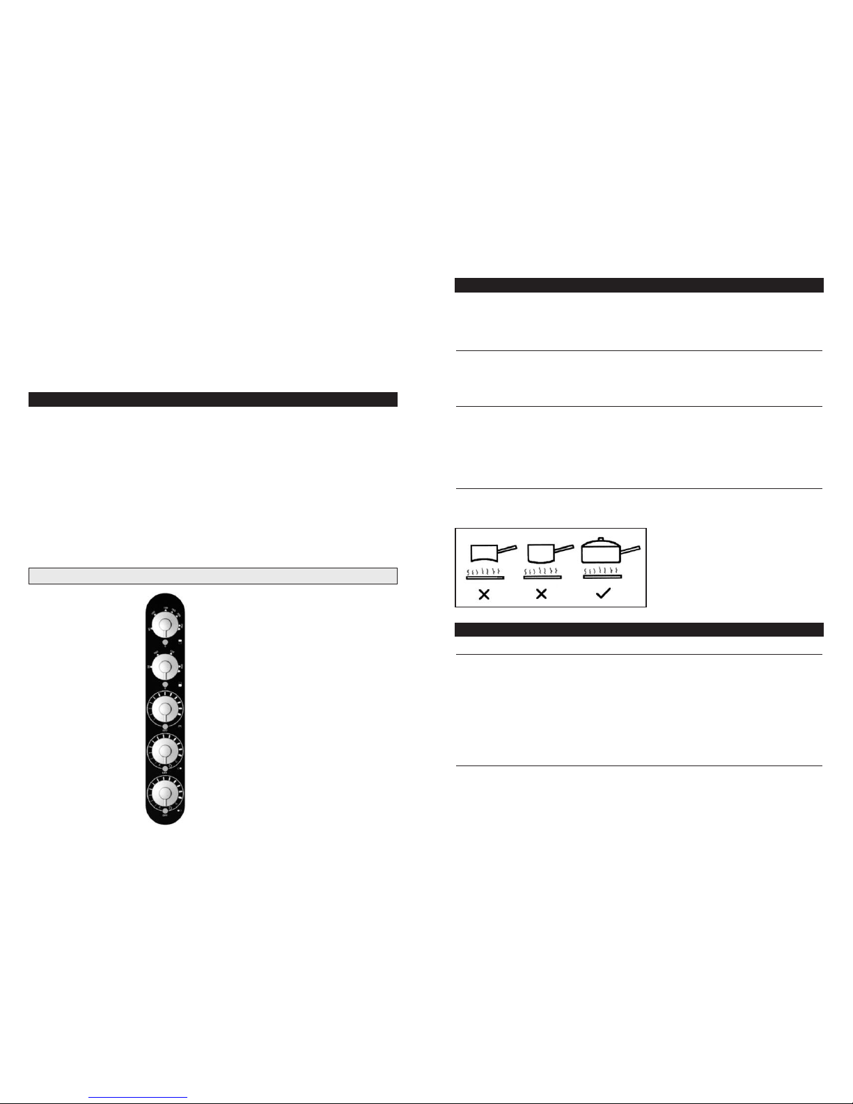
Turning t he knob clockwise past the first ring ma rking will turn ‘ON’ th e first , small centre section of
the hob. Moving the kn ob betwe en the graduated markings will n ow adjus t the temperat ure setting
of this s ection o f the hob. To increase th e size of t he heating area , turn the knob clockwise to the
next ring marking to t urn ‘ON’ the second sec tion of the hob . The temperat ure of the two combined
hob sections can the n be adjusted by movin g the knob between the graduated markings.
For maximum hob h eating area, t urn the knob fu lly cloc kwise t o the third ring m arking to turn ‘ON’
the third hob se ction. The who le hob temperature can the n be adjusted by moving the knob
betwee n the graduate d markin gs.
The cooking areas ch ange col our whe n heated (become red) indicating which heating element is
energi sed. The cookin g area returns to its original colour when the he ating element i s switched off
and cools.
Good quality pans wi th flat bases s hould be used. Thin, d ented or saucep ans with uneven bases
should not be used. D o not slide the pa ns acro ss the hob surface as th is may cause scratche s
and may l eave met al deposits, wh ich will become burnt in if not removed.
Copper pans
All copper pans are ex cellent conductors of heat, and are hardwearin g and strong, but nee d quite
a l ot of care. They can be very he avy and do not usually have completely flat bases. The interiors
are usually lined wi th a different material such as tin .
Stainl ess steel pans
A s tainless steel pan with a sandwich base of aluminium and stainless s teel is an exce llent
conduc tor of heat and is suit able fo r use on ce ramic ho bs, pro viding t hey are used in accordance
with the saucepans manufacture rs’ recommendation s. Extra care should be taken to ensu re the
base of t he pan and the hob is cleaned, an d the hob c onditioned (see BE FORE COOKING pa ge
9), after each a nd every use, when using this t ype of saucepa n.
Cast iron pans
Cast iron pans s hould have smoo th, well machin ed bases . Cast iron pan s with rough ba ses may
scratc h the hob s urface.
Top Oven Control
Bottom Oven Control
Grill Control
Right Side Hob Control
Left Side Hob Control
Operation
Pans
Operat ion
The large top ov en and the smal ler bottom oven work in an identical manner and are contro lled
thermo statically. To swi tch one of the ovens ‘O N’ turn the cor responding knob on the con trol pa nel
clockw ise to the requ ired tem perature marking. The temperature markings on the control panel are
in degrees Celsius. The indicator light w ill ill uminate to sho w that the oven is heating up. W hen the
oven reaches the req uired te mperature the indi cator light wil l go out. Fo r even cooking the ove n is
heated by two elements, one at the top of the ove n and the o ther und erneath the ov en base .
All the shelves c an be used in the top or the bottom oven .
Top Oven Temperature Guide
A t hermometer in the door giv es an indicati on of the oven te mperature, but sin ce it is in the doo r
itself, the thermometer will react if the door is opened and th e Thermo meter r eading m ay fall
consid erably. Whe n the door is clos ed, the thermomete r will recover slowly to ind icate the oven
temper ature.
Ovens
Warning ! Even though t he cooking area has ret urned t o its original colour it may still b e hot.
Page 5
98
Heatin g
With the bott om oven turned on at a low setting the cook er will become warm to the touch and wi ll
radiat e heat into the kitchen. At a setting of 80 ºC the bottom oven wil l consume appro ximately 1 /3
kW of ele ctricity per h our.
Conden sation
Conden sation will be produced when cooking food with a high water co ntent, especially if the body
of the co oker is cold. Before co oking, pre-heat the oven un til the cast ir on door becomes warm,
this will reduce the amount of condensati on when food is produced.
Excess condensation may be prod uced when the ovens are operat ed for the firs t few times an d this
will commonly show it self in the door thermometer. This will reduce each time the ovens are used.
Oven Safety Points
•
Food or utensils s hould not be placed on th e base of the oven, as it gets very hot.
•
When using the oven shelves ensure the shelv es are correctly placed between the shelf runners.
Frost Protection
If the kitchen falls below 5ºC the top oven may
operate even if the control knob is in the OFF
position.
Warning ! The front, top and doors of the
cooker may become hot after l ong per iods of
cookin g. Keep children and pets away. door is
closed , the thermome ter will recove r slowly to
indica te the oven tem perature.
Warning! Accessible parts may become hot when the grill is in use. Children shou ld be kep t away.
Note: the Grill wi ll not operate unless the Top O ven control is in the off posi tion. On ly use the gril l
with the top ove n door open.
Operat ion
Turn the control knob c lockwise to cl ick ‘ON’ the
grill and continue tu rning cl ockwise to inc rease t he
grilli ng temperature. Or, turn and click t he grill knob
anti-c lockwise to in stantly turn ‘ ON’ the grill a t
maximum setting. T he knob c an be tur ned clockwise
or anticlockwise bac k to ‘0’ to switch ‘OFF’ the grill.
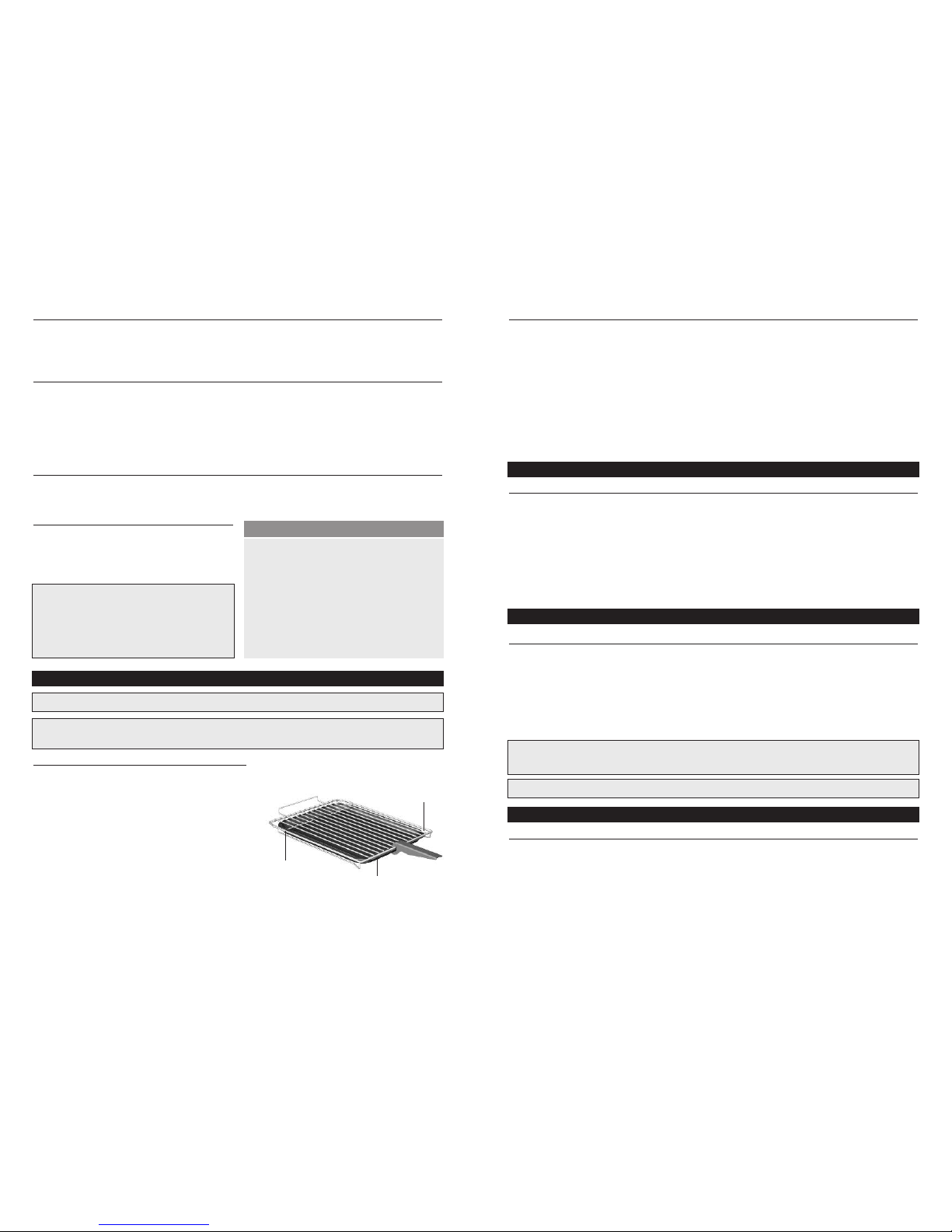
When grilling, the cake tray s upplied can be slid
under the gril l shelf for cat ching c rumbs or fat. The
grillp an handle will work onl y if the grill tra y is
correc tly in position under the gr ill shel f.
Grillp an HandleGrill Safety Points
•
When attaching the grill-pa nhandle, make sure i t is in the middle of the grill p an.
•
Do not le ave the grillpan handle attached to the grillpan whilst grilling, as it will b ecome ho t.
Use it on ly when moving the gri llpan.
•
Only operate the gri ll with the top oven do or open .
•
Ensure that th e grill pan is correct ly place d betwe en the shelf runners when grilling.
•
The towel rail m ay become HOT after long periods using the g rill.
•
Do not pl ace towe ls or any o ther it ems over the towel rail when grilling.
•
Do not li ne the grill pan w ith alu minium f oil.
Cleani ng
The warming cupboard is not indepe ndently heated but pi cks up heat fro m the top a nd the bottom
oven. The temperature of the warmin g cupboa rd depe nds on the temperatur e in the to p and the
bottom oven and the length of time for whic h eithe r oven has been on . As a rough guide , the
warmin g cupboard will reach a temperature of 60ºC after t he top oven has been on for one h our. A
plate rack is supplied in th e warmi ng cupbo ard for holding up to eight p lates, b ut this can be
remove d to allow larger items to be warmed. CAUTION If the cooker is ON for prolonged p eriods
any plates in th e warmi ng cupbo ard may become very hot.
Remove Protective Door L iners.
Before you cook for the first t ime,it is reco mmended that t he top and the bottom o ven be switched
on at ful l power for about one hour in ord er turn to burn off any initia l odours . The grill should also
be turned on, wi th the top oven door open, for approximat ely 15 minutes before it is used for the
first time. Also, bef ore you use the ceramic hob f or the first time, clean the ho b surfa ce with
Cerami c Hob Cleaner and Conditioner. This appli es a thin p rotective film to the hob, making it
easier to clea n, and prolonging its life.
Hob Cleaning
It is rec ommended that the hob be cleaned dai ly with Hob Bri te clean er. No rmally cleaning should
be carried out w hen the hob has cooled, but, if jam, fruit or anyt hing wi th a high s ugar con tent is
spille d on the ho b, or plastic or aluminium is melted onto t he hob, clean i t off immediat ely, as
damage to the hob can result. Switch off t he hob and use a metal spatula, palette knife or scrape r
to remove the sp illage. TAKE CAR E, as the spil lage and the hob m ay be very hot.
Oven/Grill Shelf
Grillpan Handle
Grillpan/Shallow Baking Tray
Oven Temperatu res Heat Up Time
Gas Mark F° C° Min utes
1 275 140 19
2 300 150 20
3 325 170 22
4 350 180 23
5 375 190 25
6 400 200 27
7 450 230 30
9 475 240 34
Grill
Warming Cupboard (Non Boiler Model)
Before Cooking
Cleaning
Warning! For y our own safety, always swi tch off your co oker at the mai ns suppl y and allow
coolin g before cleani ng.
Note: Neve r use excessiv e amounts of water to cle an your cooker.
Page 6
1110
Do not us e scouri ng powders or paste, wire woo l scouri ng pads , or oven c leaners on the hob as
these can caus e damag e to the ho b surfac e.
Oven Cleaning
Both the ovens a nd the warming cupboard can be cleaned using n ormal ov en clea ners. Th e shelf
suppor ts in the t op and the bott om ovens can be removed to make cleaning easier.
Genera l Cleaning
Enamel is simply a coloured glass c oating a dded to the met al to give a dura ble and hygienic
finish . It can be damaged by sc ratching or by a sudde n appli cation o f cold liquids onto i ts surfa ce
when hot. Clean with a cloth a nd soapy water, preferably while the coo ker is still wa rm. Prop riety
non-sc ratch liquid cl eaners f or enam elled su rfaces may be used. S pilled l iquids should be
remove d as soon a s possible. Frui t juices and other acidic products can rem ove the gloss s urface
from the enamel if lef t for any l ength of time. A stain less st eel clea ner can be used for cleaning t he
hob lids, the do or handles and the control kno bs. Do not use scouring powders or paste s,
scouri ng pads, or oven cleaners on the control panel facia plate as this may damage the markings.
The cooker does not re quire re gular servicing, but has bee n design ed so that internal components
are easy to repl ace in the even t that they bec ome faul ty. I t is preferabl e that access t o intern al
parts is gaine d by removing the lef t hand side panel. If th ere are kitchen units up to the side of the
cooker preventing access to the left h and side panel, then a ccess to intern al parts can be gained
by hinging up th e cooker top.
All the oven and grill elements can be removed and replaced from the front of the cooker through
the oven openings.
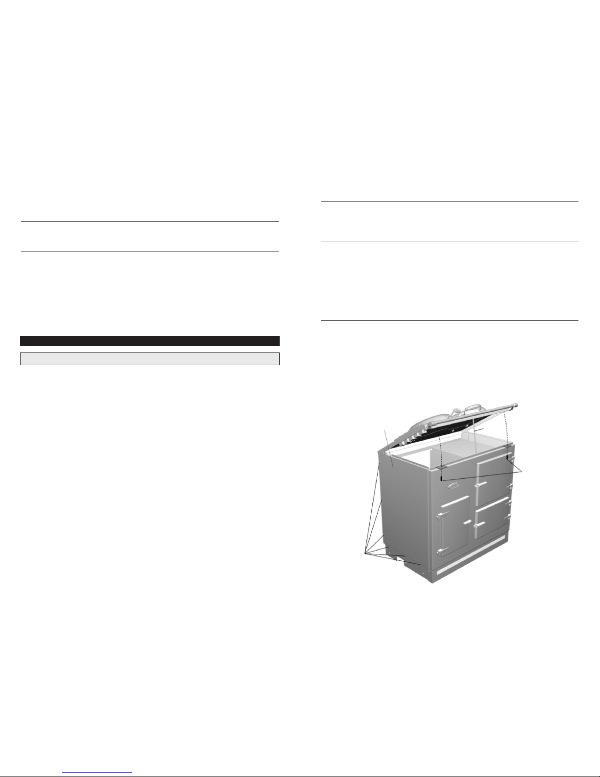
To Remove The Sid e Panel
See figure on th e next page.
1. Remove the th ree sel f tappin g screws from the side of the cooker.
2. Remove the th ree scr ews alon g the base of the cooker.
Servicing Instructions
Warning! Isolate the electrical supply before any repair work.
To Hinge The Cook er Top see figure below.
1. Undo t he two screws holding the top down. Slowly lift up the top until the lim it chai n stops the
top lifting up any higher. P ull up the prop and be careful to po sition i t correctly in the recess on the
unders ide of the top.
To Remove The Bas e Eleme nt From Top Or Bottom Oven.
1. Remove the sh elves a nd shelf supports from the oven.
2. Remove the tw o screw s holdin g down the oven base at each side. Remove the base.
3. Undo t he screw fastening the ele ment to the sid e of the ov en. The element can th en be pulled
out of th e base of t he oven. The el ectrical wire connection s should stay attached to the element as
it is pul led from the oven. The element wire t erminals can t hen be swapped from th e fault y elemen t
to the ne w elemen t. Take care not to let the element wire co nnections fall bac k inside the co oker
before they are recon nected to the new elem ent.
To Remove The Upp er Elem ents/Grill Element From Th e Top Or Bottom Oven.
1. Undo t he singl e screw fastening the elem ent to the side of the oven.
2. Loosen the sc rews on the ele ment support br ackets. The su pport br ackets can the n be rotated
clear of the elements allowing the elements to fall.
3. The electric al wire c onnections shou ld stay a ttached to the element as it is lowered. The element
wire terminals can then be swapped from the faulty element to the new o ne. Take care not to let the
element wire conne ctions fall back insid e the coo ker before they are reconnected to the new eleme nt.
Access to the following parts ca n be gained by
removi ng the cooker l eft hand side panel:
•
The hob, grill a nd oven controls.
•
The neon indicators
•
The terminal block
•
The limit thermosta t
Access to the following parts ca n be gained by
hingin g the cooker top (the to p should only be
hinged if the repair work ca nnot be carried out
by removing the cook er left hand si de panel ):
•
The hob, grill a nd oven controls.
•
The neon indicators
•
The terminal block
•
The limit thermosta t
•
The hob e lements
Side panel
secur ing sc rews
Left hand s ide pa nel
Top securing screws
Prop
Page 7

WIRE No. FROM TO LENGTH
TERM MARK TERMINAL FROM TERM MARK TERMINAL TO
1 R- P1 RED RH HOB CONTROL (P1) T- N RED TERMINAL BLOCK NEUTRAL 500
2 R- 4 RED RH HOB CONTROL (4) R- 41 RIGHT ANGLE RH HOB CONTROL (4) 130
3 R- 4a RED RH HOB CONTROL (4a) 3R RED RIGHT HOB ELEMENT (3) 800
4 R- 2 RED RH HOB CONTROL (2) 2R RED RIGHT HOB ELEMENT (2) 800
5 R- 4b RIGHT ANGLE RH HOB CONTROL (4b) 4R RED RIGHT HOB ELEMENT (4) 850
6 R- 42 RIGHT ANGLE RH HOB CONTROL (4) 1R RED RIGHT HOB ELEMENT (1) 850
7 R- S1 BLUE RH HOB CONTROL (S1) R- P2 RED RH HOB CONTROL (P2) 130
8 R- S1 BLUE RH HOB CONTROL T- L RED TERMINAL BLOCK LIVE 500
9 L- P1 RED LH HOB CONTROL (P1) T-N RED TERMINAL BLOCK NEUTRAL 500
10 L- 4 RED LH HOB CONTROL (4) L- 41 RIGHT ANGLE LH HOB CONTROL (4) 130
11 L- 4a RED LH HOB CONTROL (4a) 3L RED LEFT HOB ELEMENT (3) 800
12 L- 2 RED LH HOB CONTROL (2) 2L RED LEFT HOB ELEMENT (2) 800
13 L- 4b RIGHT ANGLE LH HOB CONTROL (4b) 4L RED LEFT HOB ELEMENT (4) 850
14 L- 42 RIGHT ANGLE LH HOB CONTROL (4) 1L RED LEFT HOB ELEMENT (1) 850
15 L- S1 BLUE LH HOB CONTROL (S1) L- P2 RED LH HOB CONTROL (P2) 130
16 L- S1 BLUE LH HOB CONTROL T- L RED TERMINAL BLOCK LIVE 500
17 T- L RED TERMINAL BLOCK LIVE S- 2 RED LIMIT SWITCH (S2) 130
18 T- N BLUE TERMINAL BLOCK NEUTRAL G- P2 PIGGY BACK GRILL CONTROL (P2) 480
19 T- N BLUE TERMINAL BLOCK NEUTRAL LINK PIGGY BACK TOP & BOTTOM OVEN NEON (NEUTRAL) 330
20 G- P2 RED GRILL CONTROL-( P2) N1 BLUE TOP OVEN UPPER ELEMENT ( NEUTRAL) 1740
21 N2 BLUE GRILL ELEMENT (NEUTRAL) N1 BLUE TOP OVEN UPPER ELEMENT ( NEUTRAL) 265
22 N2 BLUE GRILL ELEMENT (NEUTRAL) N3 BLUE TOP OVEN BASE ELEMENT ( NEUTRAL) 530
23 N4 BLUE TOP OVEN BASE ELEMENT (NEUTRAL) N3 BLUE TOP OVEN BASE ELEMENT ( NEUTRAL) 270
24 N5 BLUE BOTTOM OVEN UPPER ELEMENT ( NEUTRAL) N5 BLUE BOTTOMOVEN UPPER ELEMENT ( NEUTRAL) 295
25 N6 BLUE BOTTOM OVEN BASE ELEMENT ( NEUTRAL) N5 BLUE BOTTOM OVEN UPPER ELEMENT ( NEUTRAL)460
26 TO- F PIGGY BACK TOP OVEN LOAD (F) TO BLUE TOP OVEN UPPER ELEMENT( LOAD) 1690
28 TO BLUE TOP OVEN BASE ELEMENT (LOAD) TO BLUE TOP OVEN UPPER ELEMENT( LOAD) 570
29 TO BLUE TOP OVEN BASE ELEMENT (LOAD) TO RED TOP OVEN BASE ELEMENT (LOAD) 290
27 G- 2 RED GRILL CONTROL (2) GRILL RED 1700
30 BO- F PIGGY BACK BOTTOM OVEN CONTROL (F) BO BLUE BOTTOM OVEN UPPER ELEMENT (LOAD) 2020
31 BO BLUE BOTTOM OVENBASE ELEMENT (LOAD) BO BLUE BOTTOM OVEN UPPER ELEMENT (LOAD) 470
32 S- 1 RED LIMIT SWITCH (S1) TO- H RED TOP OVEN CONTROL (H) 300
33 TO- G BLUE TOP OVEN CONTROL (G) TO- 1 RED TOP OVEN CONTROL (SWITCH) 200
34 TO- G BLUE TOP OVEN CONTROL (G) BO- G RED BOTTOM OVENCONTROL (G) 130
35 TO- 2 RIGHT ANGLE TOP OVEN CONTROL (SWITCH) G- P1 RED GRILL CONTROL (P1) 200
36 T- VE RED TERMINAL BLOCK (EARTH) E1 M5 RED EARTH 1 900
37 T- VE RED TERMINAL BLOCK (EARTH) E2 M5 RED EARTH 2 500
38 T- VE BLUE TERMINAL BLOCK (EARTH) E3 M5 RED EARTH 3 80
39 T- VE BLUE TERMINAL BLOCK (EARTH) E4 M5 RED EARTH 4 370
40 TN N5
1312
Page 8
1514
ESSE EC fault finding
Ovens/ Grill not worki ng
• C heck the control dial. If the g rub screw is loose the contro l dial will turn without the switch turning.
• C heck all the electrical termi nal connections.
• C heck that the limit thermost at is turned fully clockwis e
Ovens not getting hot enough
• C heck that the limit thermost at is turned fully clockwis e.
• C heck that both the uppe r and lower elements in the oven ar e gettin g warm.
• C heck all the electrical termi nal connections.
• C heck that the thermostat prob e is correctly positioned in the oven.
• I f all the a bove ar e OK, the thermostat may require re -calibratin g via the a djustment screw on the
thermo stat, or replac e the oven thermostat .
Neon indicator not working
• C heck the neon termina l connec tions.
• I f the neon connectio ns are OK a nd the corresp onding o ven/grill/hob is working, then replace the
contro l panel assembly. ( The fiv e neon indicat ors and control panel are on e assemb ly).
Hob not w orking o r only partially working
• C heck all electr ical terminal c onnections.
• S wapping the te rminal connection s across from the right h ob element to the left, o r vice versa
will help determine if the hob swi tch is faulty.
Conden sation in the oven
• C heck the oven door makes a good seal.
• C heck the oven vent is not blocked.
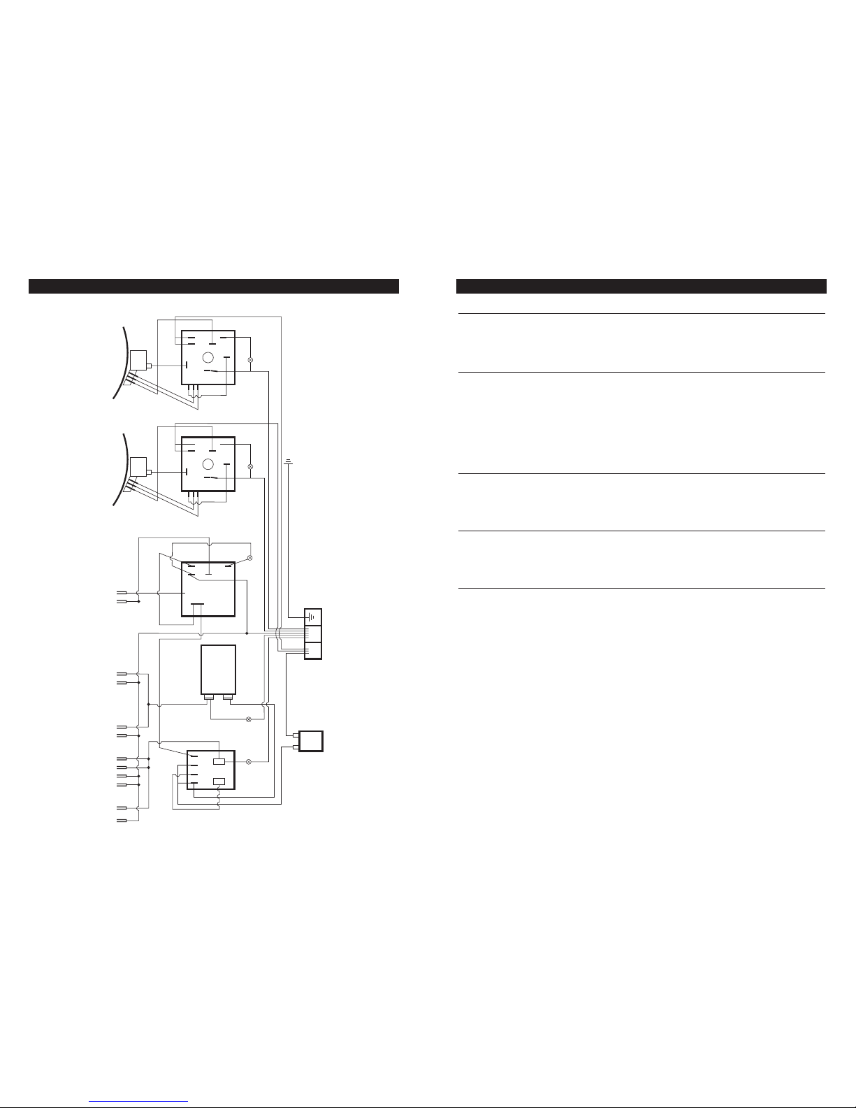
TOP OVEN
2 1
6 P6
LAMP LAMP
TOHTOG
TOF
TOF
TO2
BOF
BOF
BOG
S2S1
TOP OVEN
UPPER ELEMENT
TOP OVEN
LOWER ELEMENT
BOTTOM OVEN
UPPER ELEMENT
BOTTOM OVEN
LOWER ELEMENT
N6 BON5 BOTO TON3N4TON1
GRILL ELEMENT
N2
GRILL
GRILL
L N
LG
G2
2
P1
P2
GP1
PILOT
S1
S2
GP2
LAMP
1
2
BOTTOM
OVEN
LIMIT
SWITCH
GP2
RIGHT HOB
CONTROL
LEFT HOB
CONTROL
RIGHT HOB ELEMENT LEFT HOB ELEMENT
SECONDARY EARTH POINTS:
1. TOP CASTING
2. FRONT CASTING
3. COOKER BASE
4. TERMINAL BLOCK SUPPORT BRACKET
P5 5
Wiring diagram
 Loading...